CATHODIC ARC DEPOSITION OF FILMS - ustc.edu.cnstaff.ustc.edu.cn/~fuzp/course/paper/Cathodic Arc...
27
Annu. Rev. Mater. Sci. 1998. 28:243–69 Copyright c 1998 by Annual Reviews. All rights reserved CATHODIC ARC DEPOSITION OF FILMS Ian G. Brown Lawrence Berkeley National Laboratory, Berkeley, California 94720; e-mail: [email protected] KEY WORDS: vacuum arcs, films, plasma deposition, surface modification ABSTRACT Cathodic arc deposition is a plasma-based technology for the fabrication of films. The process can be carried out either at high vacuum or in a low pressure gaseous environment, and films can be formed for example of metals, ceramics, diamond- like carbon, some semiconductors and superconductors, and more. The plasma stream can be filtered to remove microdroplet contamination, and the ion energy can be controlled by substrate bias, thereby transforming the straightforward deposition method into hybrids with other surface modification processes such as ion beam–assisted deposition, ion beam mixing, and ion implantation. The method provides a versatile and powerful plasma tool for the synthesis of novel and technically important surfaces. INTRODUCTION The cathodic arc is a low-voltage, high-current plasma discharge that takes place between two metallic electrodes in vacuum. The earliest work in this area dates back to the late 1800s. Reviews of vacuum arc plasma discharges have been presented by Cobine (1), Lafferty (2), and more recently by Boxman et al (3). A remarkably complete bibliography containing much of the his- tory of the vacuum arc research literature up to 1986 has been compiled by Miller (4). Biennial conferences in the field have been held regularly for many years (5), and many of the papers presented have been published in archived journals (6). The published proceedings of other, related conference series also offer a rich source of material in the field (7, 7a–c). The cathodic arc is also called a metal vapor vacuum arc or simply a va- cuum arc, but cathodic arcs also occur at elevated gas pressure when the gas 243 0084-6600/98/0801-0243$08.00
-
Upload
trinhnguyet -
Category
Documents
-
view
223 -
download
0
Transcript of CATHODIC ARC DEPOSITION OF FILMS - ustc.edu.cnstaff.ustc.edu.cn/~fuzp/course/paper/Cathodic Arc...
P1: dpi/dpk/kdg P2: ARS/vks QC: ARS/anil T1: NBL
May 26, 1998 16:44 Annual Reviews AR059-10
Annu. Rev. Mater. Sci. 1998. 28:243–69Copyright c© 1998 by Annual Reviews. All rights reserved
CATHODIC ARC DEPOSITIONOF FILMS
Ian G. BrownLawrence Berkeley National Laboratory, Berkeley, California 94720;e-mail: [email protected]
KEY WORDS: vacuum arcs, films, plasma deposition, surface modification
ABSTRACT
Cathodic arc deposition is a plasma-based technology for the fabrication of films.The process can be carried out either at high vacuum or in a low pressure gaseousenvironment, and films can be formed for example of metals, ceramics, diamond-like carbon, some semiconductors and superconductors, and more. The plasmastream can be filtered to remove microdroplet contamination, and the ion energycan be controlled by substrate bias, thereby transforming the straightforwarddeposition method into hybrids with other surface modification processes suchas ion beam–assisted deposition, ion beam mixing, and ion implantation. Themethod provides a versatile and powerful plasma tool for the synthesis of noveland technically important surfaces.
INTRODUCTION
The cathodic arc is a low-voltage, high-current plasma discharge that takesplace between two metallic electrodes in vacuum. The earliest work in thisarea dates back to the late 1800s. Reviews of vacuum arc plasma dischargeshave been presented by Cobine (1), Lafferty (2), and more recently by Boxmanet al (3). A remarkably complete bibliography containing much of the his-tory of the vacuum arc research literature up to 1986 has been compiled byMiller (4). Biennial conferences in the field have been held regularly for manyyears (5), and many of the papers presented have been published in archivedjournals (6). The published proceedings of other, related conference series alsooffer a rich source of material in the field (7, 7a–c).
The cathodic arc is also called a metal vapor vacuum arc or simply a va-cuum arc, but cathodic arcs also occur at elevated gas pressure when the gas
2430084-6600/98/0801-0243$08.00

P1: dpi/dpk/kdg P2: ARS/vks QC: ARS/anil T1: NBL
May 26, 1998 16:44 Annual Reviews AR059-10
244 BROWN
participates significantly in the discharge processes; another kind of vacuumarc is the anodic arc with ionization processes quite different from the cathodicarc. Nevertheless, the terms cathodic arc and vacuum arc are often correctlyused interchangeably. In the present context, the importance of the cathodic arcplasma discharge lies in its copious and efficient production of metal plasma andits simplicity, features that make it well suited for film deposition applications.
The suitability of the cathodic arc plasma for film production has been rec-ognized and developed mostly in the last two decades. Earlier the phenomenonwas viewed largely as a problem to be avoided, primarily in the fields of vac-uum switching and high-voltage vacuum insulation. It was not until the 1970sthat the research field of cathodic arc film deposition was taken up by a grow-ing number of workers around the world (8–13). Industrial applications of themethod have mushroomed, and today there are many equipment manufactur-ers and users of the technology throughout the United States, Russia and otherFSU countries, Europe, and elsewhere. Excellent reviews of the field have beenpresented previously in the texts referred to above (1–3) and by Boxman et al(14, 15), Sanders (16), and others.
By far the most developed technological application at the present time is theformation of films of TiN that are both hard and decorative—titanium nitriding.The superb tribology of TiN and its gold-simulating spectral response have ledto its acceptance for coating applications in domains as diverse as machinetools and drills, low-cost jewelry, and building hardware; the excellent visualimpact of titanium nitrided pieces has presumably played not an insignificantrole in generating its wide acceptance. Although TiN films can be formed bymethods other than cathodic arc-based approaches, for many purposes cathodicarc films are superior, and this technology is widely used. A great variety ofother kinds of films are also amenable to the method, and the technology is nowbroadening rapidly. Industrially relevant processing parameters, such as size,throughput, and cost are steadily improving, and a growing understanding ofthe fundamental plasma physics and materials science involved is paving theway to new and better systems.
PLASMA PHYSICS OF THE CATHODIC ARC
At the cathode of the vacuum arc the current is concentrated at a small num-ber of discrete sites called cathode spots. The formation of cathode spots is afundamental characteristic of the vacuum arc discharge, and the physics of thespots has been studied by a number of workers (2–6, 17–27). The spot size isestimated to be in the range 1–10 microns, and the current density at the spots isof order 106–108 A cm−2. Many of the parameters of the vacuum arc plasma aredetermined by the plasma physics within the cathode spot. The spot is formed

P1: dpi/dpk/kdg P2: ARS/vks QC: ARS/anil T1: NBL
May 26, 1998 16:44 Annual Reviews AR059-10
CATHODIC ARC FILMS 245
by an explosive emission process (28, 29) and the lifetime (residence time) ofan individual spot at a fixed location has been put at from about 10 ns (30)to about a microsecond (23). New daughter spots are formed at the edges ofprevious parent spot locations, giving rise to an apparent spot motion across thecathode surface that is typical and indicative of vacuum arcs (31). Small sur-face irregularities such as sharp edges or protuberances tend to anchor the spotsto these regions. The plasma pressure within a cathode spot is high, and thestrong pressure gradient causes the plasma generated there to plume away fromthe surface in a manner similar to the plasma plume generated by an intensefocused laser beam at a solid surface. The current carried by a cathode spot istypically a few to a few tens of amperes, depending on the metal, and if the arcis caused to conduct a higher total current, then more cathode spots are formed;thus a typical cathodic arc discharge of several hundred amperes arc currentmight involve the participation of several tens of cathode spots. The assemblageof cathode spots gives rise to a dense plasma of cathode material. The plasmaplumes away from the cathode, initially normal to the cathode surface and in thegeneral direction of the anode, thereby allowing the arc current to flow and thearc to persist. There is a lower limit to arc current, called the chopping current,below which the spot will not persist; an upper limit is determined by sourcecooling requirements and the possible formation of anode spots (32). The arcvoltage (when the arc is alight, i.e. the burning voltage) lies generally in therange 10–30 V and varies according to the cathode material used. Unlike themore common high-pressure gaseous arc discharge, the cathodic arc displays apositive resistance characteristic, i.e. the arc voltage increases with arc current,albeit only slowly.
A basic feature of the vacuum arc discharge is the relationship between themetal ion flux that is generated at the cathode spots and the current that drivesthe arc (3, 20, 33). The arc current is composed of both an electron componentand an ion component. For all cathode materials and for typical arc currents inthe several hundred amperes range, the plasma ion current is a constant fractionof the arc current, Iion = εIarc, whereε ' 0.10± 0.02. Thus the electricalefficiency of plasma generation—the ratio of available metal ion plasma currentto arc current—is about 10%. The plasma ions form the substance required forfilm deposition, and thus some of the ion flux generated at the cathode spotsserves to carry the arc current (along with the much greater electron flux), andsome is diverted to be used for deposition at a location distant from the arc itself.
Along with the intense plasma flux that is generated at the cathode spots,there is also a component of cathode debris in the form of microdroplets, usu-ally called macroparticles (34) (because they are macroscopic compared withthe plasma particles). These metallic globules are ejected from the cathode inthe molten state and rapidly solidified in flight; they are typically in the range
P1: dpi/dpk/kdg P2: ARS/vks QC: ARS/anil T1: NBL
May 26, 1998 16:44 Annual Reviews AR059-10
246 BROWN
of 0.1–10µm in diameter. Macroparticle generation is less for higher meltingpoint materials, and there is also a natural separation of the macros from theplasma because the plasma flux is peaked in the forward direction whereas themacroparticle flux is peaked close to parallel to the cathode surface (≈20◦). Of-ten a magnetic duct, described below, is incorporated into the overall plasma gunconfiguration, thereby producing a metal plasma stream that is free of macropar-ticles, as well as of neutral atoms; the plasma exiting the magnetic duct filter isfully ionized. When the cathodic arc is operated in a gas background, as for ex-ample for the formation of metallic oxides or nitrides (e.g. alumina or titaniumnitride), the macroparticle generation is observed to be less than in vacuum.
The mass of plasma generated by the vacuum arc is of the order of several tensof micrograms per Coulomb of arc charge (arc current× arc on-time), wherethe precise value depends primarily on the metal used (20, 33, 35). This massgeneration efficiency is consistent with the ion current generation efficiencyε
introduced above. Macroparticle generation is an additional source of cathodemass consumption; thus the cathode mass consumed is in general greater thanthe mass of plasma produced, the difference being largely the macroparticlemass.
The metal (or carbon) plasma that is generated at the spots plumes away fromthe cathode with an ion streaming velocity in the range 1 to 3 cmµs−1 [generally,for all cathode materials (36)] that corresponds to an ion drift energy of about10 to 200 eV depending on the ion mass (37). This feature of the vacuum arcplasma—the high directed ion energy—is critically important to the virtue ofcathodic arc film deposition. The high ion deposition energy provides a kindof pseudo-temperature to the growing film that in turn provides surface atommobility and leads to high film quality. The physical phenomena involved hereare the same as for ion-beam-assisted deposition (IBAD). This serendipity canbe further extended by adding the feature of ion energy control; then the filmmorphology and structure can be optimized. This highly advantageous plasmatool is described and discussed in more detail below.
The ion charge state distributions of cathodic arc plasmas have been inves-tigated in some detail (37–40). The ions are in general multiply stripped withcharge states Qi from 1+ up to about 6+, depending on the metal species, andwith a mean charge state of from 1+ to about 3+. It is now possible to predictthe charge state distribution expected from any elemental cathode material withsome precision (40).
Triggering of vacuum arcs is an important concern. Depending on the pa-rameters and operational mode of the source involved, triggering can be doneelectronically, electromechanically, or purely mechanically, and it can be laserinitiated, gas-breakdown initiated, or surface breakdown initiated, for example(41–45).

P1: dpi/dpk/kdg P2: ARS/vks QC: ARS/anil T1: NBL
May 26, 1998 16:44 Annual Reviews AR059-10
CATHODIC ARC FILMS 247
Figure 1 Simplified schematic of basic cathodic arc configuration.
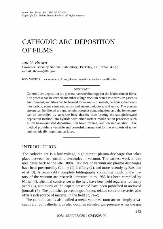
Cathodic arc plasma sources have been made in many different embodimentsfor many research and industrial uses. They span the gamut from miniaturefinger-sized research tools (46) to massive human-sized installations that pro-duce microsecond duration, low-repetition rate plasma pulses or large-area,steady state plasma streams. A simplified schematic of a basic cathodic arcconfiguration is shown in Figure 1, and a photograph of two kinds of sourcesin Figure 2. The upper photograph shows an electro-mechanically triggered dcsource with a 5 cmdiameter titanium cathode that is cooled by direct watercontact to the back side and a water-cooled cylindrical copper anode (shown re-moved). The lower photograph shows a small, uncooled source with a 3.175 mmdiameter cathode (several shown) that operates typically with sub-millisecondpulses and duty cycle≈0.1%.
THE DEPOSITION PROCESS
The film composition reflects the cathode composition, though not always ac-curately. Several different factors contribute to the non-equivalence of cathode
P1: dpi/dpk/kdg P2: ARS/vks QC: ARS/anil T1: NBL
May 26, 1998 16:44 Annual Reviews AR059-10
248 BROWN
Figure 2 Cathodic arc plasma sources.Upper: DC source with 5 cm diameter cathode.Lower:miniature, low duty cycle source with 3 mm diameter cathode.
P1: dpi/dpk/kdg P2: ARS/vks QC: ARS/anil T1: NBL
May 26, 1998 16:44 Annual Reviews AR059-10
CATHODIC ARC FILMS 249
and film composition; a primary one is the different sputtering rates of the var-ious elemental species. The growing film is bombarded by the incoming ionflux, some sputtering occurs, and the degree of sputtering is not the same fordifferent constituent elements of the film. Thus the residual (net) film compo-sition will differ from the plasma composition (47, 48). Also, the plasma itselfmay not accurately reflect the composition of the cathode, especially if somegaseous or nonmetallic species such as LaB6 or FeS2 are involved (49, 50). Forthe case of a single-element cathode, this is of course not a concern.
Oxide and nitride films can be made by operating the source at, or at leastlocating the substrate in, an elevated background gas pressure. The reactivegas pressure may be barely greater than the base pressure, e.g. in the 10−4 torrrange, or as high as several hundred millitorr.
Film thickness can be from monolayers up to microns or even many tens orhundreds of microns in some cases; thickness in the broad range 0.1–10µmis typical of the technique. Kim and coworkers (51) have formed super-thinfilms of Pt and Re for surface catalysis studies (thickness≈10A and less) usinga small filtered cathodic arc source operated in a short-pulse mode by whichfractions of a monolayer are formed per pulse. It has been shown that the filmscan be of particularly high quality, having no islands or valleys (clusters ofatoms, or local deficiencies of coverage) (52). At the other extreme, Boxmanet al (53) have designed and operated a source at spectacularly high depositionrates. In their experiments, the substrate served also as the anode, thus achievingmaximum efficiency in this respect. Coatings of Al on steel, Mo on Co, and TiNon steel were prepared, among others. Deposition rates of up to approximately0.1 mm s−1 were measured at the highest arc currents investigated of 2 kA.Maximum pulse length was about 100 ms. It is interesting to note that thepower flux carried by the arc to the substrate under these conditions was ashigh as several hundred MW m−2, an impressively high value and more thanenough to cause local melting and intermixing of the deposited material withthe substrate material, usually also with beneficial results. This work probablyholds the record at present for highest cathodic arc deposition rate. Moretypically, deposition rates of order 1–10µm h−1 are achieved.
Removal of macroparticles from the plasma (or at least reduction of macro-particle content) by passing the plasma stream through a magnetic duct macro-particle filter is becoming a common procedure, but for many applications (forexample decorative coatings) it is unnecessary and is not done. The kind ofsetup employed for filtered cathodic arc deposition is indicated schematicallyin Figure 3. Good fundamental understanding of plasma transport throughmagnetic ducts is crucial to maximizing the filter efficiency, and much progresshas been made recently in this subfield of vacuum arc plasma physics; somehighlights of this work are discussed below.

P1: dpi/dpk/kdg P2: ARS/vks QC: ARS/anil T1: NBL
May 26, 1998 16:44 Annual Reviews AR059-10
250 BROWN
Figure 3 Simplified schematic of a basic filtered arc setup using a quarter-torus solenoid.
KINDS OF FILMS
Most of the solid metals of the Periodic Table can be accessed by cathodic arcmethods (38, 39). Low-melting-point metals such as In, Sn, Pb, and otherscannot be operated dc but must be used in a low duty cycle pulsed mode to keepthe mean thermal load low. On the other hand, at typical operating pressuresin the 10−6 torr range, films of the highly reactive metals such as Li, Ca, Ba,etc, suffer gross oxidation, and many metals including Al and Ti are difficult todeposit in a completely oxygen-free state other than by a DC arc. Semiconduc-tors such as Si have been used, but with difficulty and only when highly dopedso that the bulk resistivity is sufficiently low that the cathode is able to supportconduction of the arc current. Carbon is the subject of much ongoing researchfor the formation of hydrogen-free diamond-like carbon films (see below). Therare earths, noble metals, and refractory metals in general work well.
High-quality stoichiometric nitrides and oxides can be formed by operatingat a judiciously selected background gas pressure, including, above all, TiNas well as others such as AlN, VN, CrN, ZrN, Al2O3, SiO2, TiO2, VO2, Y2O3,

P1: dpi/dpk/kdg P2: ARS/vks QC: ARS/anil T1: NBL
May 26, 1998 16:44 Annual Reviews AR059-10
CATHODIC ARC FILMS 251
ZrO2, Nb2O5, to name just a few. Carbides, for example SiC, TiC, and WC, canbe formed using a carbide cathode material or by mixing the plasmas formedfrom two separate plasma sources. Films of more complex composition, suchas TiCN, TiCrN, TiAlN, TiZrN, TiAlZrN, and others, can be formed using anappropriate alloy cathode, with a background gas ambient at the appropriatepressure. In this case, the effect of preferential sputtering (47, 48) can causethe film composition to differ from the cathode alloy composition and to bedependent upon the applied substrate bias.
Carbon films in which the bonding is a mixture of graphitic (sp2) and dia-mond (sp3) have been widely explored in recent years. This material has beengiven many different names, including diamond-like carbon or dlc; hard car-bon; amorphous carbon ora-C; amorphous diamond; and tetrahedrally bondedamorphous carbon orta-C. It can be made by many different methods includ-ing cathodic arc deposition. Some of the features of dlc made by cathodic arcdeposition include its being inherently hydrogen free (compared with someother approaches that use a hydrocarbon gas as the basic feedstock), highsp3-content (up to 85%), and high surface hardness (over 85 GPa). Some recentdevelopments in this area are discussed below.
For a more complete perspective of the panorama of film materials and struc-tures that have been made by cathodic arc deposition, see the last several yearsof the relevant conference proceedings (5–7, 7a–c).
RECENT ADVANCES IN PLASMA TECHNOLOGY
Advances have been made in a number of areas of plasma technology that areimportant for the development of cathodic arc film deposition for research andindustrial applications, including new approaches to macroparticle filtering, ionenergy control, hybridization with other nearby plasma methods and technolo-gies, and understanding of the plasma properties and behavior at a fundamentallevel.
Macroparticle FilteringMacroparticle contamination of the cathodic arc plasma is for most applicationsa disadvantage and for some a fatal defect. Most tribological and decorativeapplications would be better served by a macroparticle-reduced process, whileothers, including particularly most applications to the semiconductor and mag-netic storage industries, call for essentially macroparticle-free film deposition.There is incentive for improved theoretical models and for the development ofnew macro-filtering schemes. Much progress has been made, and a number ofnew systems and approaches have been described.

P1: dpi/dpk/kdg P2: ARS/vks QC: ARS/anil T1: NBL
May 26, 1998 16:44 Annual Reviews AR059-10
252 BROWN
The approach to macroparticle filtering that has seen the most significantprogress is the use of curved magnetic guide fields, first introduced by Aksenovand coworkers in the 1970s (10, 54, 55). Plasma from the cathodic arc sourceis injected into a bent solenoidal magnetic field region, a quarter-torus beingtypical, where the plasma stream is bent through an angle of 90◦ (Figure 3). Theplasma is transported through the duct, with some loss, while the macroparticlesare not magnetically guided and are lost from the plasma stream. The goal ofduct research is thus to increase the plasma transport efficiency through the ductand to reduce the residual macroparticle flux at the substrate location.
A detailed experimental investigation of duct plasma transport as a function ofduct parameters was made by Anders and coworkers (56–58). The importanceof the flow of magnetized electrons (electron gyro radiusρe< rd the duct minorradius) in determining the transport of unmagnetized ions (ion gyro radiusρ i> rd) via ambipolar electric fields was pointed out. For good plasma transportthe duct must be biased with respect to the plasma, typically by about+10 to+20 V, an effect noted in the pioneering work of Aksenov and coworkers. Thisfeature was recognized also by Bilek and coworkers who showed that a similareffect can be produced by applying a positive bias to a strip electrode that islocated near the outer wall of the interior of the duct (59, 60). These kinds ofoptimized 90◦ ducts can achieve a plasma transport efficiency up to about 25%.
Anders has taken the concept further in the S-duct (61), shown schematicallyin Figure 4. Here the macroparticle transport is reduced to an unmeasurablylow level by the use of two 90◦ ducts in series, but done in such a way as tooffset the curvature drift (62, 63) of the metal plasma stream toward the ductwall. The plasma transport efficiency is also reduced to about (0.25)2 or about6% for optimum operation. This draconian solution to macroparticle removal issuited to those applications where essentially no macroparticles can be toleratedand the required film thickness is small; the suitability of the approach forproducing very thin, particulate-free, diamond-like carbon protective overcoatsfor magnetic storage hard disks has been demonstrated (64, 65).
Somewhat offsetting the disadvantage of low plasma transport efficiency arethe results of Sch¨ulke and coworkers, who investigated the transport of highcurrent arc plasmas through a 90◦ duct (66). The peak arc current was up toseveral kiloamperes, and the plasma ion current at the filter exit was as muchas 7% of the arc current, for a duct transport efficiency (ratio of ion current atduct exit to that at duct entrance) of up to 35%. Extrapolation of this result toan S-duct configuration would predict usable S-duct-filtered ion current in thetens of amperes range. These impressively large plasma currents could findindustrial application.
Aksenov and coworkers have described a novel kind of geometry involving anaxially symmetric magnetic filter configuration (67), indicated schematically in

P1: dpi/dpk/kdg P2: ARS/vks QC: ARS/anil T1: NBL
May 26, 1998 16:44 Annual Reviews AR059-10
CATHODIC ARC FILMS 253
Figure 4 S-duct described by Anders and coworkers.
Figure 5. Both mirror and ring-cusp magnetic geometries (adding and opposingmagnetic field coils, respectively) were investigated. Good efficiency and highfilm deposition rates were demonstrated (10µm h−1 of TiN over 0.2 m2 subs-trate area).
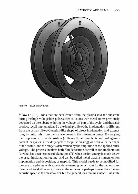
Recently an in-line magnetic filter system has been described by Ryabchikovand coworkers (68, 69). In this configuration a concentric, circular, “venetianblind” arrangement (a nested set of tapered sections) is used (see Figure 6). Areduction of two orders of magnitude in the macroparticle fraction and a plasmatransport efficiency of up to 70% were reported. This kind of system could benicely suited to large facilities.
Ion Energy ControlThe ability to control the directed energy of the cathodic arc plasma ions canbe advantageous in a number of ways, providing a means for doing ion surfacemodification similar to that of ion-beam-assisted deposition, or to ion mixing,or to ion implantation, depending on the energy regime employed. New hybridprocessing schemes that combine the different ion energy regimes can then be

P1: dpi/dpk/kdg P2: ARS/vks QC: ARS/anil T1: NBL
May 26, 1998 16:44 Annual Reviews AR059-10
254 BROWN
Figure 5 Axially symmetric macroparticle filter configuration of Aksenov and coworkers.
accessed and used in a single fabrication/modification process to make novelfilms of complex design.
Substrate bias has been successfully used as a means for controlling theion energy. Ions are accelerated at the plasma sheath that forms at the biasedsubstrate, and the deposition energy is equal to the sum of the drift energy of ionsin the plasma stream and the energy acquired in their acceleration through thesheath drop, Edep= Edrift + eQiVsheath. This straightforward approach was usedas a means for the control of microhardness of the deposited film by Aksenovand coworkers as long ago as 1977 (13). Internal compressive stress in the filmthat otherwise tends to lead to delamination and limitation of the achievablefilm thickness can also be controlled (47, 48, 70, 71).
As the substrate voltage increases, so does the sheath thickness. When ahigh-voltage pulse is applied to a substrate immersed in a plasma, the sheathrapidly expands into the plasma and the system can be severely disrupted (e.g.plasma depletion and high-voltage breakdown) if the substrate is maintainedat high voltage. One approach to solving this problem is to apply the biasvoltage in a repetitively pulsed mode; in the pulse-on period ions are acceleratedinto the substrate as required, and in the pulse-off period the plasma recovers.This technique is called plasma source ion implantation or plasma immersionion implantation (psii, piii or pi3) (72). Because of the surface retention ofcondensed metal plasma, the piii process in a metal plasma is quite differentfrom that in a gaseous plasma, and qualitatively new and different consequences
P1: dpi/dpk/kdg P2: ARS/vks QC: ARS/anil T1: NBL
May 26, 1998 16:44 Annual Reviews AR059-10
CATHODIC ARC FILMS 255
Figure 6 Ryabchikov filter.
follow (73–76). Ions that are accelerated from the plasma into the substrateduring the high-voltage bias pulse suffer collisions with metal atoms previouslydeposited on the substrate during the voltage-off part of the cycle, and thus alsoproduce recoil implantation. So the depth profile of the implantation is differentfrom the usual shifted-Gaussian-like shape of direct implantation and extendsroughly uniformly from the surface down to the maximum range. By varyingthe proportions of the deposition (voltage-off) and implantation (voltage-on)parts of the cycle (i.e. the duty cycle of the pulse biasing), one can tailor the shapeof the profile, and the range is determined by the amplitude of the applied pulsevoltage. The process involves both film deposition as well as ion implantation[or what has been termed subplantation (71) when the ion energy is much belowthe usual implantation regime] and can be called metal plasma immersion ionimplantation and deposition, or mepiiid. This model needs to be modified forthe case of a plasma with substantial streaming velocity, as for the cathodic arcplasma where drift velocity is about the same as or perhaps greater than the ionacoustic speed in the plasma (37), but the general idea remains intact. Substrate
P1: dpi/dpk/kdg P2: ARS/vks QC: ARS/anil T1: NBL
May 26, 1998 16:44 Annual Reviews AR059-10
256 BROWN
bias provides control over an important deposition parameter—the ion energy.Although the global need for the bias to be applied in a repetitively pulsedmode, as opposed to dc, is not yet completely clear for the case of a plasmawith high drift velocity, it is certain that repetitively pulsed operation offers acloser control over the high-voltage sheath behavior, and the risk of breakdownor other unwanted plasma behavior can be avoided. The method provides atool for nano-engineering the film in some important ways; the interface widthcan be tailored, and the film morphology and structure can to a large extent becontrolled.
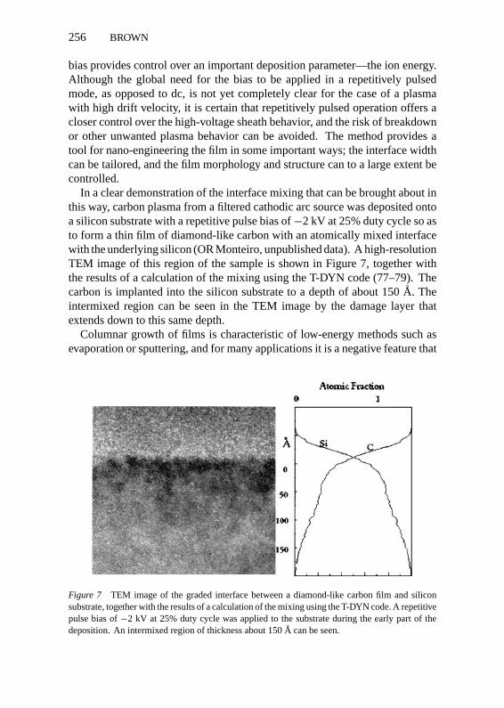
In a clear demonstration of the interface mixing that can be brought about inthis way, carbon plasma from a filtered cathodic arc source was deposited ontoa silicon substrate with a repetitive pulse bias of−2 kV at 25% duty cycle so asto form a thin film of diamond-like carbon with an atomically mixed interfacewith the underlying silicon (OR Monteiro, unpublished data). A high-resolutionTEM image of this region of the sample is shown in Figure 7, together withthe results of a calculation of the mixing using the T-DYN code (77–79). Thecarbon is implanted into the silicon substrate to a depth of about 150A. Theintermixed region can be seen in the TEM image by the damage layer thatextends down to this same depth.
Columnar growth of films is characteristic of low-energy methods such asevaporation or sputtering, and for many applications it is a negative feature that
Figure 7 TEM image of the graded interface between a diamond-like carbon film and siliconsubstrate, together with the results of a calculation of the mixing using the T-DYN code. A repetitivepulse bias of−2 kV at 25% duty cycle was applied to the substrate during the early part of thedeposition. An intermixed region of thickness about 150A can be seen.

P1: dpi/dpk/kdg P2: ARS/vks QC: ARS/anil T1: NBL
May 26, 1998 16:44 Annual Reviews AR059-10
CATHODIC ARC FILMS 257
needs to be removed. The columnarity can be removed by adding a concur-rent energetic ion beam bombardment, i.e. IBAD. The inhibition of columnargrowth by the enhanced adatom mobility brought about by ion bombardment ofsputtered films has been nicely shown by Olbrich & Kampschulte in a series ofedge-on scanning electron microscope (SEM) photographs (80). Cathodic arcdeposition has an inherent IBAD-like feature due to the high ion drift energy, asdescribed above, and this feature can be vastly expanded via substrate biasing.This important attribute of the approach was noted by Martin and coworkers(81–83). Good control over the columnarity can be achieved.
The film-substrate adhesion can be enhanced by atomic mixing at the inter-face. In this case the ion energy is kept high, at some keV or greater. At thisenergy ions are implanted into the substrate to a depth of≈100A or more, de-pending on the film and substrate atomic species, and a highly mixed interfaceis produced. When a film thickness of the same order as the interface widthhas accumulated, the pulse bias voltage is reduced since intermixing with thesubstrate is no longer a factor. Higher ion energy would simply sputter awaythe already deposited film, and the film is built up by deposition at a lower butoptimized energy.
The effect of substrate bias changes as the bias increases, and thus conven-tionally used terminology also changes. For low bias (low ion energy)—inthe range tens of eV up to several hundred eV—the phenomena involved aresimilar to IBAD; in this range the film morphology and structure can be tai-lored. For intermediate bias (intermediate ion energy)—several hundred eVto several keV—sputtering is important and ion penetration becomes signifi-cant; this range is appropriate for control of the film-substrate interface andlayer-to-layer interfaces of a multilayer structure. For yet higher bias (high ionenergy)—from several keV to≈100 keV—the appropriate way of viewing theinteraction is as a more-or-less straightforward energetic ion implantation. Itis a powerful method that should engender many advances with many variants.For a more complete survey of this subfield, see References 72–76. Some ex-amples of the use of these methods to specific film synthesis applications aregiven below.
Thickness UniformityFilm thickness uniformity is a general concern. Mechanical scanning of thesubstrate or magnetic scanning of the plasma column are two approaches thathave been used. Another method is the use of an array of permanent magnetsin the form of a magnetic bucket (84, 85). This kind of magnetic geometryhas been long used for the confinement of laboratory plasmas of various kinds(86–88), and it also works well for cathodic arc plasmas. The deposition pro-file (radial distribution of deposited film thickness) follows the plasma density
P1: dpi/dpk/kdg P2: ARS/vks QC: ARS/anil T1: NBL
May 26, 1998 16:44 Annual Reviews AR059-10
258 BROWN
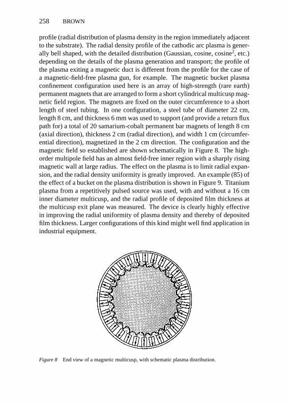
profile (radial distribution of plasma density in the region immediately adjacentto the substrate). The radial density profile of the cathodic arc plasma is gener-ally bell shaped, with the detailed distribution (Gaussian, cosine, cosine2, etc.)depending on the details of the plasma generation and transport; the profile ofthe plasma exiting a magnetic duct is different from the profile for the case ofa magnetic-field-free plasma gun, for example. The magnetic bucket plasmaconfinement configuration used here is an array of high-strength (rare earth)permanent magnets that are arranged to form a short cylindrical multicusp mag-netic field region. The magnets are fixed on the outer circumference to a shortlength of steel tubing. In one configuration, a steel tube of diameter 22 cm,length 8 cm, and thickness 6 mm was used to support (and provide a return fluxpath for) a total of 20 samarium-cobalt permanent bar magnets of length 8 cm(axial direction), thickness 2 cm (radial direction), and width 1 cm (circumfer-ential direction), magnetized in the 2 cm direction. The configuration and themagnetic field so established are shown schematically in Figure 8. The high-order multipole field has an almost field-free inner region with a sharply risingmagnetic wall at large radius. The effect on the plasma is to limit radial expan-sion, and the radial density uniformity is greatly improved. An example (85) ofthe effect of a bucket on the plasma distribution is shown in Figure 9. Titaniumplasma from a repetitively pulsed source was used, with and without a 16 cminner diameter multicusp, and the radial profile of deposited film thickness atthe multicusp exit plane was measured. The device is clearly highly effectivein improving the radial uniformity of plasma density and thereby of depositedfilm thickness. Larger configurations of this kind might well find application inindustrial equipment.
Figure 8 End view of a magnetic multicusp, with schematic plasma distribution.

P1: dpi/dpk/kdg P2: ARS/vks QC: ARS/anil T1: NBL
May 26, 1998 16:44 Annual Reviews AR059-10
CATHODIC ARC FILMS 259
Figure 9 Radial profile of film deposition thickness with and without the use of a magneticmulticusp.
Plasma MixingPlasmas from two separate cathodic arc sources have been combined to forma blended plasma of ion species from both sources. Films can be formed ofcomposition that can be tailored over a wide range. The method has long beenused to form alloy coatings, for example of TiC, by running an arc on cathodesof Ti and C simultaneously (15). A schematic of the setup used by Monteiroand coworkers (89–92) is shown in Figure 10. Two repetitively pulsed cathodicarc plasma sources, with their separate magnetic ducts for macroparticle fil-tering, are mixed together before reaching the substrate. Optionally, a shortmagnetic multipole of the kind described above has been used to better blendthe two plasmas and to produce a more uniform plasma density profile; in thissituation, the magnetic multipole configuration has been called a plasma ho-mogenizer. The deposition can be carried out synchronously or asynchronously,i.e. the plasma sources can be operated simultaneously or sequentially. Whenoperated synchronously, the film material is a controlled mixture of speciesfrom both cathodic arc sources; the plasma guns may be operated with dif-ferent pulse lengths and the stoichiometry of the film constituents controlled.When operated sequentially, multilayer structures can be formed. Some of thenovel kinds of films that have been made in this way are described below.

P1: dpi/dpk/kdg P2: ARS/vks QC: ARS/anil T1: NBL
May 26, 1998 16:44 Annual Reviews AR059-10
260 BROWN
Figure 10 Schematic of the dual plasma mixing configuration of Monteiro and coworkers.
Hot CathodesThe use of hot cathodes (up to about 1000◦C) has been explored by severalworkers. There are two reasons for interest in this mode of operation—thepossibility of macroparticle-free operation as the arc runs in a spotless, diffusemode rather than the more usual spot-mode (93), and the possibility of accessingnormally insulating cathode materials, particularly boron, by virtue of theirincreased electrical conductivity at high temperature.
Veerasamy and coworkers (94) have operated a carbon vacuum arc to formhard carbon films on silicon substrates using three configurations and opera-tional modes: unfiltered cathodic spot arc, filtered cathodic spot arc, and unfil-tered cathodic “distributed” arc; filtering, when done, was by a 90◦ magneticduct of conventional design. The films were examined by a number of methods,
P1: dpi/dpk/kdg P2: ARS/vks QC: ARS/anil T1: NBL
May 26, 1998 16:44 Annual Reviews AR059-10
CATHODIC ARC FILMS 261
including atomic force microscopy, for their surface morphology. The filmsformed using the distributed arc mode and without any macroparticle filteringwere found to be similar in structure to and as dense as films grown from thefiltered cathodic spot arc. Chhowalla and coworkers (94a, b) have pursuedthis work further and conclude that the low macroparticle content of the carbonplasmas generated by these cathodes, and also of the diamond-like carbon filmsformed, is a consequence not of the high cathode temperature but of the deeperosion holes that are formed in the compressed graphite cathode. They referto this arc mode as a stationary carbon arc because the discharge remains local-ized throughout its lifetime within a single high-aspect ratio hole in the cathode.The plasma formed has increased stability and a greatly reduced macroparticlecontent. This method for the deposition of diamond-like carbon films with lowor reduced macroparticle content could have industrial importance.
Richter and coworkers have made an important advance in demonstratingthat boron plasma can be formed by the cathodic arc process using a hot boroncathode (95–97). The cathode was heated up to about 1000◦C by a surroundingoven, and as a result of additional power input during arc operation, parts of thesurface rose further to over 2000◦C. A combined diffuse mode and spot modewas observed. Macroparticles continued to be generated and were removedfrom the boron plasma stream by subsequent magnetic filtering. The facility wasused to form cubic boron nitride (cBN) thin films by reactive deposition of boronplasma in a nitrogen background (97). This demonstration that dense boronplasma can be formed in copious quantity in this way could have importantimplications for hard film synthesis and possibly also to the semiconductorcommunity.
NOVEL FILMS AND APPLICATIONS
The diversity of the kinds of film materials and structures, and the applicationsto which the films have been put, have both seen impressive advances in recentyears. Films of metals and alloys, including non-equilibrium alloys, high-quality diamond-like carbon, ceramics of many different kinds, semiconductors,high-temperature superconductors, and others have been formed, both as single-layer films and as multilayer structures. In the following, a number of novelareas are briefly described. (See also 3, 6, 7, 7a–c, 98 for complete and detaileddiscussion of these and other kinds of cathodic arc films and application areas).
Diamond-Like CarbonDiamond-like carbon (dlc) films have been the subject of a great deal of re-search effort over the past decade or so (7, 7a–c, 98). This material is a mixtureof graphitically bonded (sp2) and diamond-bonded (sp3) carbon atoms, and
P1: dpi/dpk/kdg P2: ARS/vks QC: ARS/anil T1: NBL
May 26, 1998 16:44 Annual Reviews AR059-10
262 BROWN
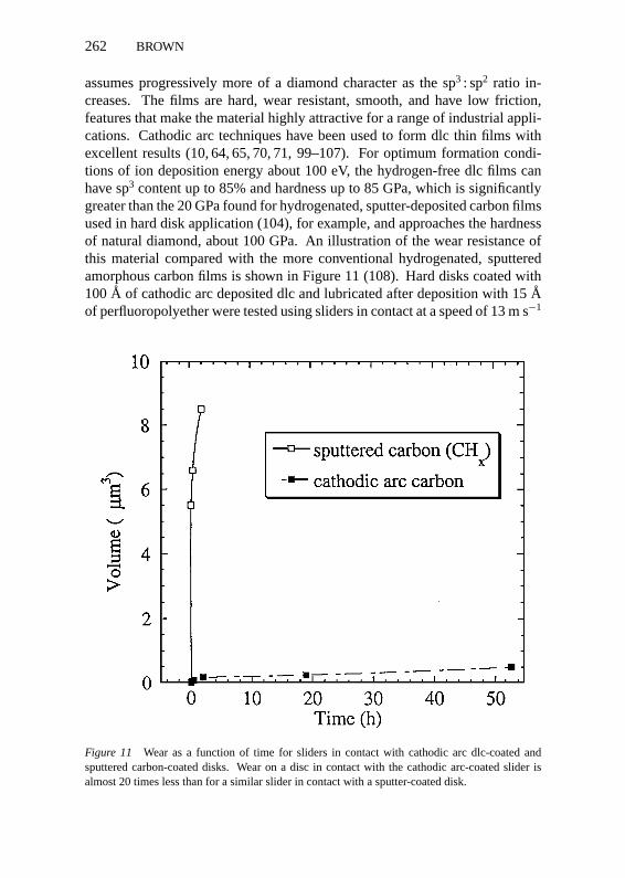
assumes progressively more of a diamond character as the sp3 : sp2 ratio in-creases. The films are hard, wear resistant, smooth, and have low friction,features that make the material highly attractive for a range of industrial appli-cations. Cathodic arc techniques have been used to form dlc thin films withexcellent results (10, 64, 65, 70, 71, 99–107). For optimum formation condi-tions of ion deposition energy about 100 eV, the hydrogen-free dlc films canhave sp3 content up to 85% and hardness up to 85 GPa, which is significantlygreater than the 20 GPa found for hydrogenated, sputter-deposited carbon filmsused in hard disk application (104), for example, and approaches the hardnessof natural diamond, about 100 GPa. An illustration of the wear resistance ofthis material compared with the more conventional hydrogenated, sputteredamorphous carbon films is shown in Figure 11 (108). Hard disks coated with100A of cathodic arc deposited dlc and lubricated after deposition with 15Aof perfluoropolyether were tested using sliders in contact at a speed of 13 m s−1
Figure 11 Wear as a function of time for sliders in contact with cathodic arc dlc-coated andsputtered carbon-coated disks. Wear on a disc in contact with the cathodic arc-coated slider isalmost 20 times less than for a similar slider in contact with a sputter-coated disk.

P1: dpi/dpk/kdg P2: ARS/vks QC: ARS/anil T1: NBL
May 26, 1998 16:44 Annual Reviews AR059-10
CATHODIC ARC FILMS 263
Figure 12 TEM image of a hard-soft dlc multilayer structure made by cathodic arc depositionwith modulated ion energy.
and a load of 40 mg; the worn volume is plotted as a function of time and is afactor of 20 lower for the cathodic arc dlc than for the sputter-coated disk.
Multilayer structures of high sp3 content and low sp3 content dlc also havebeen made (108, 109), as shown in Figure 12. By periodically varying the carbonion energy, the layers of the structure can be modulated in their properties suchas density, hardness, and internal stress. This kind of hard-soft dlc multilayeredstructure provides an additional degree of freedom to the film characteristics,and the overall compressive growth stress of the film can be reduced while stillmaintaining a very hard and wear-resistant surface. Other kinds of multilayereddlc structures have also been made, for example with TiC/dlc layers (110) andwith layers doped with Ti or W (111).
Cubic Boron NitrideCubic boron nitride (cBN) is of interest for a variety of applications becauseof its extreme hardness, high thermal conductivity, high electrical resistance,chemical inertness, and optical transparency. cBN films have been made bymany different PVD and CVD methods, but a cathodic arc approach has beendifficult because boron is not an electrical conductor and thus cannot be usedas a cathode material, at least not at and near room temperature. However, animportant advance made recently by Richter and coworkers is that they have

P1: dpi/dpk/kdg P2: ARS/vks QC: ARS/anil T1: NBL
May 26, 1998 16:44 Annual Reviews AR059-10
264 BROWN
made and operated a cathodic arc source with a boron cathode operating atabout 1000◦C, i.e. when boron becomes a good conductor (as described above)(95–97). Films were made that were almost 100% cubic phase, of quality com-parable to the best films made by other methods such as magnetron sputtering.
CeramicsCeramic films of many different kinds have been made for many years bycathodic arc deposition, but this broad applications area has been enhancedgreatly by the growing using of filtered plasmas to form macroparticle-free (or-reduced) ceramic films such as Al2O3 (74, 82, 112–114) and many other metaloxides such as VO2, ZrO2, TiO2, and Nb2O5. Highly adherent 3Al2O3 · 2SiO2alumina-silica (mullite) films that maintain their integrity and adhesion through-out repeated high-temperature cycling have been made using the methods de-scribed above (89, 90), e.g. mixed plasmas of aluminum and silicon in the pres-ence of a low-pressure oxygen background, with repetitively pulsed substratebias for ion energy control. In the early stages of the process, the ion energywas held in the keV range to produce atomic mixing at the film-substrate inter-face, and in the latter stages of deposition, the energy was reduced to≈100 eVto optimize the film structure and morphology. The film-substrate adhesion wastypically greater than≈70 MPa (the limit of measurement), and the films main-tained their adhesion after repetitive cycling in temperature between ambientand 1000◦C.
Semiconducting MaterialsFilms of silicon and other semiconductors can be formed by cathodic arc depo-sition under somewhat restrictive conditions. The poor electrical conductivityof undoped silicon makes it unsuitable as a vacuum arc cathode material, buthighly doped material has a sufficiently low resistivity that it can be used (115).Boxman and coworkers (116) have made and explored in some detail films ofheavily boron-doped amorphous silicon and of undoped amorphous SnO2−x(an n-type semiconductor), and conclude that cathodic arc deposition meth-ods could provide a valuable technology in some specialized semiconductingthin film applications such as for solar cells, flat panel displays, windshielddefrosters, and other devices.
In the related field of rare earth optoelectronic materials, rare earth elementssuch as Er are used to dope thin film materials, for example, alumina to pro-duce the required optical characteristics. Raoux and coworkers (117) have madeAl2O3 and Al2−xErxO3 thin films as a preliminary demonstration of the use ofpulsed vacuum arc methods for the fabrication of multilayer waveguide struc-tures such as Al2O3/Al2−xErxO3/Al2O3/Si. An Al1.92Er0.08O3/Si film, 2000Athick, was made using an Al/Er(10%) cathode.
P1: dpi/dpk/kdg P2: ARS/vks QC: ARS/anil T1: NBL
May 26, 1998 16:44 Annual Reviews AR059-10
CATHODIC ARC FILMS 265
Superconducting MaterialsBoth low-temperature and high-temperature superconducting thin films havebeen made by cathodic arc methods. Bendavid and coworkers (83) have formedniobium thin films on silicon. The films were of cubic phase and had relativelyhigh superconducting critical temperatures (Tc) of about 9 K and residual re-sistivity ratios of up to 28.2. NbN films were also made, with a Tc of 11.0 Kand residual resistivity ratio of 1.2. High-Tc superconducting films, includingYBa2Cu3O7−δ films by Studer and coworkers (118) and Bi2Sr2CaCu2Oy/Ag(50 wt.%) films by Chae and coworkers (119), have been made by cathodicarc deposition followed by a post-deposition annealing phase. Tc onset wasapproximately 85 K in both cases. In spite of the encouraging results found inthese preliminary investigations, the method has not been adopted as a generalsuperconducting thin film synthesis technology.
BiomaterialsApplications of cathodic arc methods to a number of different biomedical areashave been explored to some extent. One important field is for the formation ofbiologically compatible hard coatings for orthopedic implants such as prosthetichip and knee joints, although at present, the main concern is wear of the ultra-high molecular weight polyethylene (UHMWPE) mating component rather thanthe metallic part itself. Diamond-like carbon could have particular promise inthis application (120), as well as for broader biological applications, becauseof its very high surface hardness and low wear as well as its biocompatibility.Zirconia is another material that has received some attention. In other work,several different kinds of biocompatible and bioactive surface coatings thatcan promote and stabilize cell attachment to medical instruments have beenformed and explored by Ignatius and coworkers (121). The films were testedon primary central nervous system neurons and the growth response was verygood. The method and the materials could have ramifications in a numberof areas of research and biotechnology, for example for chronic implantationof microelectrode arrays in the cerebral cortex for neuroprosthetic and neuralmonitoring application, and for research on the human central nervous system.
SUMMARY
Research and development in cathodic arc film deposition has been active andgrowing in recent years. Understanding of the basic plasma physics involvedcontinues to advance, and numerous important new ways of manipulating andcontrolling the plasma and the deposition process have been developed. Ac-ceptance of the technology throughout industry remains somewhat limited,although use in a number of particular areas is growing. The film material

P1: dpi/dpk/kdg P2: ARS/vks QC: ARS/anil T1: NBL
May 26, 1998 16:44 Annual Reviews AR059-10
266 BROWN
properties can be excellent, and the range of kinds of materials that can be pro-duced is impressive and still growing. The presence of macroparticles in theplasma stream is a disadvantage for some, but not all, applications, and there isa need for simple and high-efficiency macroparticle filter systems; some of thefilter systems described here may fill this need for some applications. Scale-upto greater plasma througput and higher film deposition rates is needed for someapplications, and future advances in this area could engender a greater appealfor the technology from certain industries. As an area of scientific research, thefield is very healthy.
Visit the Annual Reviews home pageathttp://www.AnnualReviews.org.
Literature Cited
1. Cobine JD. 1962.Elec. Eng.81:13–212. Lafferty JM, ed. 1980.Vacuum Arcs—
Theory and Application.New York: Wi-ley
3. Boxman RL, Martin PJ, Sanders DM,eds. 1995.Vacuum Arc Science and Te-chnology.New York: Noyes
4. Miller HC. 1988.A Bibliography and Au-thor Index for Electrical Discharges inVacuum(1897–1986). Schenectady, NY:General Electric Co. Doc. GEPP-TIS-366e (UC-13). Published in part 1990.IEEE Trans. Elec. Insul.25:765–860;1991. IEEE Trans. Elec. Insul.26:949–1043
5. Proc. Int. Symp. Discharges and Electri-cal Insulation in Vacuum (ISDEIV)
6. Special Issues on Vacuum Discharge Plas-mas in IEEE Trans. Plasma Sci. 1993.IEEE Trans. Plasma Sci.21:397–608;1995. 23:877–1025; 1997. 25:519–762
7. Proc. Int. Conf. Metallurgical Coatingsand Thin Films (ICMCTF), published1994.Surf. Coat. Technol.68/69:1–840;1995. 76/77:1–874; 1996. 86/87:1–846;1994.Thin Solid Films253:1–543; 1995.270:1–652; 1996. 290/291:1–540
7a. Proc. Int. Conf. Ion Beam Modificationof Materials (IBMM), published 1993.Nucl. Instrum. Methods B;80/81:1–1538;1995. 106:1–1136; 1997. 127/128:1–1048
7b. Proc. Int. Conf. Surface Modification ofMetals by Ion Beams (SMMIB), pub-lished 1994.Surf. Coat. Technol.66:1–542; 1996. 83:1–614
7c. Proc. Am. Vacuum Society Symp. (AVS),published 1995.J. Vac. Sci. Tech. A.
13:503–1818; 1996. 14:609–1972; 1997.15:445–1800
8. Sablev LP, Dolotov YI, Getman LI, Gor-bunov VN, Goldiner EG, et al. 1974.U.S.Patent No. 3783231
9. Sablev LP, Dolotov YI, Stupak RI, OsipovVA. 1976.Prib. Techkh. Ebsp.4:247–49
10. Aksenov II, Vakula SI, Padalka VG,Strel’nitskii VE, Khoroshikh VM. 1980.Sov. Phys. Tech. Phys.25:1164–66
11. Snaper AA. 1971.U.S. Patent No.3625848;1974.U.S. Patent No. 3836451
12. Gilmour AS Jr, Lockwood DL. 1972.Proc. IEEE60:977–91
13. Aksenov II, Bren VG, Padalka VG,Khoroshikh VM. 1979.Sov. Phys. Tech.Phys.23:651–53
14. Boxman RL, Goldsmith S, Shalev S,Yaloz H, Brosh N. 1986.Thin Solid Films139:41–52
15. Boxman RL. 1989.IEEE Trans. PlasmaSci17:705–11
16. Sanders DM. 1989.J. Vac. Sci. Tech. A7:2339–45
17. Plyutto AA, Ryzhhov VN, Kapin AT.1965.Sov. Phys. JETP20:328–37
18. Davis WD, Miller C. 1969.J. Appl. Phys.40:2212–21
19. Kimblin CW. 1971.Proc. IEEE59:546–55
20. Kimblin CW. 1973.J. Appl. Phys.44:3074–78
21. Daalder JE. 1975.J. Phys. D: Appl. Phys.8:1647–59
22. Hantzsche E. 1993.IEEE Trans. PlasmaSci.21:419–25
23. Siemroth P, Schultrich B, Sch¨ulke T.1995.Surf. Coat. Technol.74/75:92–96

P1: dpi/dpk/kdg P2: ARS/vks QC: ARS/anil T1: NBL
May 26, 1998 16:44 Annual Reviews AR059-10
CATHODIC ARC FILMS 267
24. Lunev VM, Padalka VG, KhoroshikhVM. 1977.Sov. Phys. Tech. Phys.22:858–61
25. Chaly AM, Logatchev AA, Shkol’nikSM. 1997.IEEE Trans. Plasma Sci.25:564–70
26. Siemroth P, Sch¨ulke T, Witke T. 1997.IEEE Trans. Plasma Sci.25:571–79
27. Lyubimov GA, Rakhovski VI. 1978.Sov.Phys. Usp.21:693–718
28. Hantzsche E, J¨uttner B, Puchkarov VF,Rohrbeck W, Wolff H. 1976.J. Phys. D:Appl. Phys.9:1771–81
29. Anders A, Anders S, F¨orster A, BrownIG. 1992.Plasma Sources Sci. Technol.1:263–70
30. Anders A, Anders S, J¨uttner B, BotticherB, Luck H, Schroder G. 1992.IEEETrans. Plasma Sci.20:466–72
31. Schulke T, Siemroth P. 1996.IEEE Trans.Plasma Sci.24:63–64
32. Miller HC. 1985.IEEE Trans. Plasma Sci.13:242–52
33. Kimblin CW. 1974.J. Appl. Phys.45:5235–44
34. Daalder JE. 1976.J. Phys. D: Appl. Phys.9:2379–95
35. Brown IG, Shiraishi H. 1990.IEEE Trans.Plasma Sci.18:170–71
36. Kutzner J, Miller HC. 1992.J. Phys. D:Appl. Phys.25:686–93
37. Krinberg IA, Lukovnikova MP. 1996.J.Phys. D: Appl. Phys.29:2901–6
38. Brown IG, Godechot X. 1991.IEEETrans. Plasma Sci.19:713–17
39. Brown IG. 1994.Rev. Sci. Instrum.65:3061–81
40. Anders A. 1996.Phys. Rev. E55:969–81
41. Watt GC, Evans PJ. 1993.IEEE Trans.Plasma Sci.21:547–51
42. Anders A, Brown IG, MacGill RA, Dick-inson MR. 1998.J. Phys. D: Appl. Phys.31:584–87
43. Nikolaev AG, Yushkov GY, Oks EM,MacGill RA, Dickinson MR, Brown IG.1996.Rev. Sci. Instrum.67:3095–98
44. Boxman RL. 1977.IEEE Trans. ElectronDevices.24:122–28
45. Govinda Raju GR, Hackman R, BensonFA. 1977.J. Appl. Phys.48:1101–5
46. MacGill RA, Dickinson MR, Anders A,Monteiro OR, Brown IG. 1998.Rev. Sci.Instrum.69:801–3
47. Martin PJ, Bendavid A, Wielunski LS,Katardjiev I, Berg S. 1997.Nucl. Instr.Meth. B129:207–9
48. Martin PJ, Bendavid A, Kinder TJ. 1997.IEEE Trans. Plasma Sci.25:675–79
49. Sasaki J, Brown IG. 1989.J. Appl. Phys.66:5198–203
50. Sasaki J, Sugiyama K, Yao X, Brown IG.1993.J. Appl. Phys.73:7184–87
51. Kim C, Ogletree DF, Salmeron MB,Godechot X, Somorjai GA, Brown IG.1992.Appl. Surf. Sci.59:261–66
52. Salvadori MC, Galvao RM, Monteiro OR,Brown IG. 1998.Thin Solid Films.Inpress
53. Boxman RL, Goldsmith S, Shalev S,Yaloz H, Brosh N. 1985.Thin Solid Films139:41–52
54. Aksenov II, Belous VA, Padalka VG,Khoroshikh VM. 1978.Sov. J. PlasmaPhys.4:425
55. Aksenov II, Belokhvostnikov AN, Padal-ka VG, Repalov NS, Khoroshikh VM.1986.Plasma Phys. Control. Fusion28:761
56. Anders S, Anders A, Brown IG. 1994.J.Appl. Phys.75:4895–99
57. Anders A, Anders S, Brown IG. 1994.J.Appl. Phys.75:4900–5
58. Anders A, Anders S, Brown IG. 1995.Plasma Sources Sci. Technol.4:1–12
59. Bilek MMM, McKenzie DR, Yin Y,Chowalla M, Milne WI. 1996. IEEETrans. Plasma Sci.24:1291–98
60. Bilek MMM, Yin Y, McKenzie DR. 1996.IEEE Trans. Plasma Sci.24:1165–73
61. Anders S, Anders A, Dickinson MR,MacGill RA, Brown IG. 1997. IEEETrans. Plasma Sci.25:670–74
62. Spitzer L Jr. 1965. InPhysics of Fully Ion-ized Gases,pp. 3–9. New York: Wiley-Interscience
63. Chen FF. 1974. InIntroduction to PlasmaPhysics,pp. 23–26. New York: Plenum
64. Bhatia CS, Anders S, Bobb K, Hsiao R,Bogy DB, Brown IG. 1998.J. Tribol. Inpress
65. Anders S, Brown IG, Bhatia CS, BogyDB. 1997. Data Storage,Oct. pp. 31–38
66. Schulke T, Anders A, Siemroth P. 1997.IEEE Trans. Plasma Sci.25:660–64
67. Aksenov II, Belous VA, KhoroshikhVM. 1996. Proc. XVIIth Int. Symp. onDischarges & Elec. Insul. in Vacuum,Berkeley, pp. 895–99. IEEE Cat. No.96CH35939
68. Ryabchikov AI, Stepanov IB. 1998.Rev.Sci. Instrum.69:810–12
69. Ryabchikov AI, Stepanov IB, DektjarevSV, Sergeev OV. 1998.Rev. Sci. Instrum.69:893–95
70. Fallon PJ, Veerasamy VS, Davis CA,Robertson J, Aramatunga GAJ, et al.1993.Phys. Rev. B48:4777–82
71. McKenzie DR, Muller D, Pailthorpe BA,Wang ZH, Kravtchinskaia E, et al. 1991.Diamond Relat. Mater.1:51–59
P1: dpi/dpk/kdg P2: ARS/vks QC: ARS/anil T1: NBL
May 26, 1998 16:44 Annual Reviews AR059-10
268 BROWN
72. Proc. Int. Workshop on Plasma-Based IonImplantation, published 1994.J. Vac. Sci.Technol. B12:815–998; 1996.Surf. Coat.Technol.85:1–124; 1997. 93:158–350
73. Brown IG, Godechot X, Yu KM. 1991.Appl. Phys. Lett.58:1392–94
74. Brown IG, Anders A, Anders S, Dickin-son MR, Ivanov IC, et al. 1993.Nucl. In-strum. Meth. B80/81:1281–87
75. Anders A, Anders S, Brown IG, Dickin-son MR, MacGill RA. 1994.J. Vac. Sci.Tech. B12:815–20
76. Anders A. 1997.Surf. Coat. Technol.93:158–67
77. Biersack JP. 1987.Nucl. Instrum. Meth. B27:21–36
78. Biersack JP. 1987.Nucl. Instrum. Meth. B19/20:32–39
79. Ziegler JF, Biersack JP, Littmark U. 1985.The Stopping and Range of Ions in Matter.New York: Pergamon
80. Olbrich W, Kampschulte K. 1993.Surf.Coat. Technol.61:262–67
81. Martin PJ, Netterfield RP, McKenzie DR,Falconer IS, Pacey CG, et al. 1987.J. Vac.Sci. Tech. A5:22–28
82. Martin PJ, Netterfield RP, Kinder TJ.1990.Thin Solid Films193/194:77–83
83. Bendavid A, Martin PJ, Netterfield RP,Sloggett GJ, Kinder TJ, Andrikidis C.1993.J. Mater. Sci. Lett.13:322–23
84. Anders S, Raoux S, Krishnan K, MacGillRA, Brown IG. 1996.J. Appl. Phys.79:6785–90
85. Anders S, MacGill RA, Raoux S, BrownIG. 1996. Proc. XVIIth Int. Symp. onDischarges & Elec. Insul. in Vacuum,Berkeley, pp. 909–12. IEEE Cat. No.96CH35939
86. Limpaecher R, McKenzie KR. 1973.Rev.Sci. Instrum.44:726–31
87. Ault ER, McKenzie KR. 1973.Rev. Sci.Instrum.44:1697–99
88. Leung KN. 1994.Rev. Sci. Instrum.65:1165–69
89. Monteiro OR, Wang Z, Hou PY, BrownIG. 1997. Nucl. Instrum. Meth. B127/128:821–26
90. Monteiro OR, Wang Z, Brown IG. 1997.J. Mater. Res.12:2401–10
91. Delplancke-Ogletree MP, Monteiro OR.1997.J. Vac. Sci. Tech. A15:1943–50
92. Brown IG, Anders A, Dickinson MR,MacGill RA, Monteiro OR. 1998.Surf.Coat. Technol.In press
93. Anders S, Anders A. 1991.IEEE Trans.Plasma Sci.19:20–24
94. Veerasamy VS, Amaratunga GAJ, WeilerM, Park JS, Milne WI. 1994.Surf. Coat.Technol.68/69:301–8
94a. Chhowalla M, Davis CA, Weiler M,
Kleinsorge B, Aramatunga GAJ. 1995.Appl. Phys. Lett.67:894–96
94b. Chhowalla M, Davis CA, Weiler M,Kleinsorge B, Aramatunga GAJ. 1995.J.Appl. Phys.79:2237–44
95. Richter F, Krannich G, Hahn J, PintaskeR, Friedrich M, et al. 1997.Surf. Coat.Technol.90:178–83
96. Richter F, Flemming G, K¨uhn M, Peter S,Wagner H. 1998.Surf. Coat. Technol.Inpress
97. Krannich G, Richter F, Hahn J, PintaskeR, Filippov VB, Paderno Y. 1997.Dia-mond Relat. Mater.6:1005–9
98. Proc. Eur. Conf. Diamond, Diamond-likeand Related Materials, published 1996.Diamond Relat. Mater.5:197–881; 1997.6:191–925
99. Aksenov II, Strel’nitskij VE. 1991.Surf.Coat. Technol.47:98–105
100. Koskinen J, Anttila A, Hirvonen JP. 1991.Surf. Coat. Technol.47:180–87
101. Tochitsky EI, Selifanov OV, Akulich VV,Kapustin IA, Stanishevskii AV. 1991.Surf. Coat. Technol.47:292–98
102. Coll BF, Sathrum P, Aharonov R, TamorMA. 1992.Thin Solid Films209:165–73
103. Anders S, Anders A, Brown IG, Wei B,Komvopoulos K, et al. 1994.Surf. Coat.Technol.68/69:388–93
104. Pharr GM, Callahan DL, McAdams SD,Tsui TY, Anders S, et al. 1996.Appl. Phys.Lett.68:779–81
105. Schwan J, Ulrich S, Roth H, EhrhardtH, Silva SRP, et al. 1996.J. Appl. Phys.79:1416–22
106. Shi X, Tay BK, Flynn DI, Sun Z. 1997.Mater. Res. Soc. Symp. Proc.436:293–98
107. Scheibe HJ, Schultrich B, Ziegele H,Siemroth P. 1997.IEEE Trans. PlasmaSci.25:685–88
108. Anders S, Callahan DL, Pharr GM, TsuiTY, Bhatia CS. 1997.Surf. Coat. Technol.94/95:189–94
109. Ager J III, Anders S, Brown IG, NastasiM, Walter KC. 1997.Surf. Coat. Technol.91:91–94
110. Delplancke-Ogletree MP, Monteiro OR,Brown IG. 1997.Mater. Res. Soc. Symp.Proc.438:639–44
111. Monteiro OR, Delplancke-Ogletree MP,Ager JW, Brown IG. 1997.Mater. Res.Soc. Symp. Proc.438:599–604
112. Randhawa H. 1989.J. Vac. Sci. Tech. A7:2346–49
113. Schemmel TD, Cunningham RL, Rand-hawa H. 1989.Thin Solid Films181:597–601
114. Hou PY, Alexander KB, Wang Z, BrownIG. 1996. InElevated Temperature Coat-ings: Science and Technology II, ed.

P1: dpi/dpk/kdg P2: ARS/vks QC: ARS/anil T1: NBL
May 26, 1998 16:44 Annual Reviews AR059-10
CATHODIC ARC FILMS 269
NB Dahotre, JM Hampikian, pp. 187–97.Warrendale, PA: TMS
115. Naoe M, Yamanaka S. 1969.Jpn. J. Appl.Phys.8:287–88
116. Boxman RL, Goldsmith S, Ben-ShalomA, Kaplan L, Arbilly D, et al. 1995.IEEETrans. Plasma Sci.23:939–44
117. Raoux S, Brown IG, Anders S, Yu KM,Ivanov IC. 1995.Mater. Res. Soc. Symp.Proc.392:241–46
118. Studer AJ, McKenzie DR, Cockayne
DJH, Smith GB, Brown IG. 1992.Phys.C 197:147–50
119. Chae MS, Simnad MT, Maple MB, An-ders S, Anders A, Brown IG. 1996.Phys.C 270:173–79
120. Dowling DP, Kola PV, Donnelly K, KellyTC, Brumitt K, et al. 1997.Diamond Re-lat. Mater.6:390–93
121. Ignatius MI, Sawhney N, Gupta A,Thibadeau BM, Monteiro OR, Brown IG.1998.J. Biomed. Mater. Res.In press


![Introduction - Shodhgangashodhganga.inflibnet.ac.in/bitstream/10603/4037/7/07_chapter 1.pdf · B) Vacuum arc vapour deposition [9]: In arc vapour deposition, the material deposition](https://static.fdocuments.in/doc/165x107/5e282f350175b03995481f03/introduction-1pdf-b-vacuum-arc-vapour-deposition-9-in-arc-vapour-deposition.jpg)
![Early Years of Commercial Cathodic Arc Vapor Deposition ... · is well documented in the book, Cathodic Arcs, From Fractal Spots to Energetic Condensation [1]. The research performed](https://static.fdocuments.in/doc/165x107/5f0d17fb7e708231d438a5cb/early-years-of-commercial-cathodic-arc-vapor-deposition-is-well-documented-in.jpg)