Caterpillar Gettingstarted Guide
91
CATERPILLAR Service Technician Workbench Getting Started Guide Version 2006A 1
Transcript of Caterpillar Gettingstarted Guide

CATERPILLAR
Service Technician Workbench Getting Started Guide
Version 2006A
1

Notice The information contained in this package may be used by Caterpillar dealers or customers under a signed License Agreement, including the requirement that the information be maintained in confidence, and no part shall be transferred to, disclosed to, or used by others. As updates to data libraries and upgrades to software are received from Caterpillar, all previous versions of such software and data libraries must be removed from use and destroyed. Service Technician Workbench CDs/DVDs should be locked in a cabinet or desk when not in use and access limited to those requiring the information for the internal operations of the license.
2
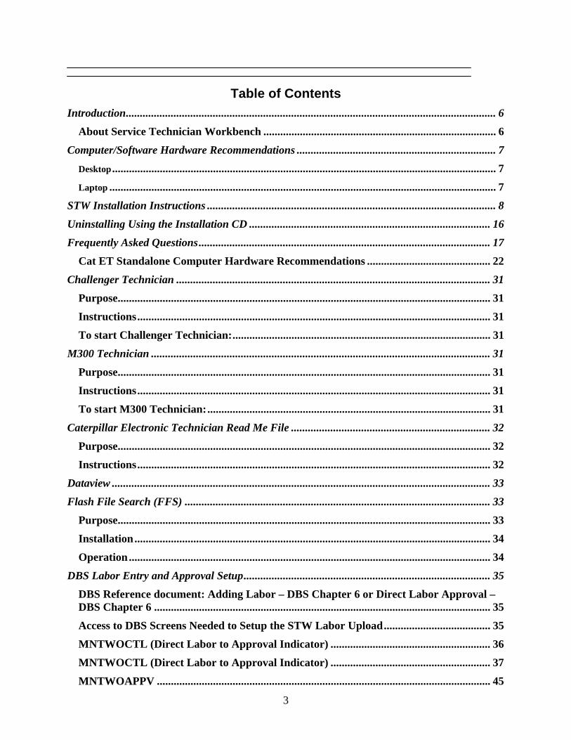
Table of Contents Introduction.................................................................................................................................... 6
About Service Technician Workbench ................................................................................... 6
Computer/Software Hardware Recommendations ....................................................................... 7
Desktop......................................................................................................................................... 7
Laptop .......................................................................................................................................... 7
STW Installation Instructions ....................................................................................................... 8
Uninstalling Using the Installation CD ...................................................................................... 16
Frequently Asked Questions........................................................................................................ 17
Cat ET Standalone Computer Hardware Recommendations ............................................ 22
Challenger Technician ................................................................................................................ 31
Purpose..................................................................................................................................... 31
Instructions.............................................................................................................................. 31
To start Challenger Technician:............................................................................................ 31
M300 Technician ......................................................................................................................... 31
Purpose..................................................................................................................................... 31
Instructions.............................................................................................................................. 31
To start M300 Technician:..................................................................................................... 31
Caterpillar Electronic Technician Read Me File ....................................................................... 32
Purpose..................................................................................................................................... 32
Instructions.............................................................................................................................. 32
Dataview ....................................................................................................................................... 33
Flash File Search (FFS) ............................................................................................................. 33
Purpose..................................................................................................................................... 33
Installation............................................................................................................................... 34
Operation................................................................................................................................. 34
DBS Labor Entry and Approval Setup........................................................................................ 35
DBS Reference document: Adding Labor – DBS Chapter 6 or Direct Labor Approval – DBS Chapter 6 ........................................................................................................................ 35
Access to DBS Screens Needed to Setup the STW Labor Upload...................................... 35
MNTWOCTL (Direct Labor to Approval Indicator) ......................................................... 36
MNTWOCTL (Direct Labor to Approval Indicator) ......................................................... 37
MNTWOAPPV ....................................................................................................................... 45
3
4
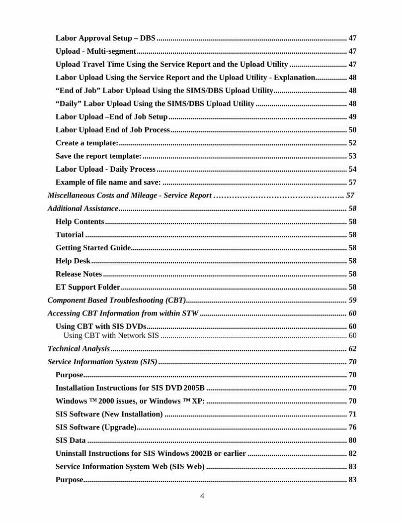
Labor Approval Setup – DBS ................................................................................................ 47
Upload - Multi-segment.......................................................................................................... 47
Upload Travel Time Using the Service Report and the Upload Utility ............................. 47
Labor Upload Using the Service Report and the Upload Utility - Explanation................ 48
“End of Job” Labor Upload Using the SIMS/DBS Upload Utility..................................... 48
“Daily” Labor Upload Using the SIMS/DBS Upload Utility .............................................. 48
Labor Upload –End of Job Setup.......................................................................................... 49
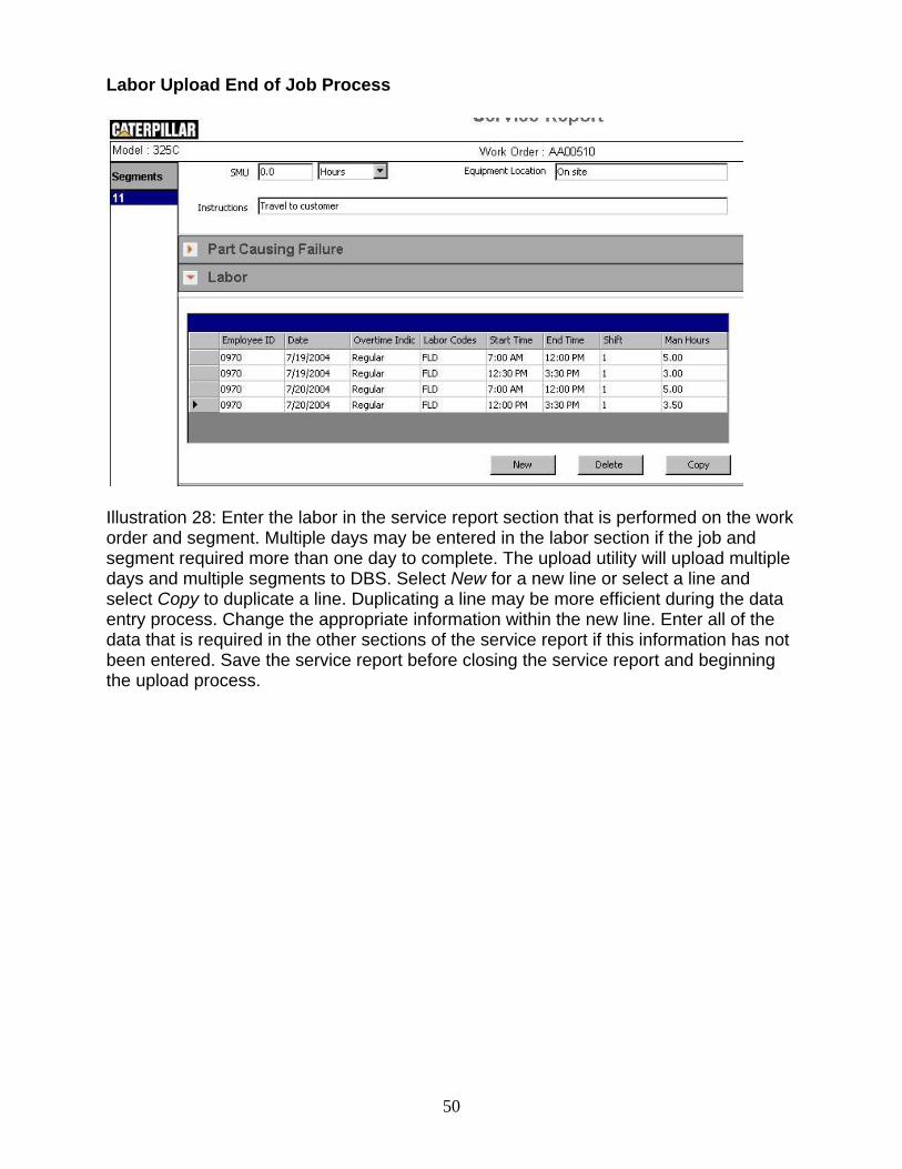
Labor Upload End of Job Process......................................................................................... 50
Create a template:................................................................................................................... 52
Save the report template: ....................................................................................................... 53
Labor Upload - Daily Process ................................................................................................ 54
Example of file name and save: ............................................................................................. 57
Miscellaneous Costs and Mileage - Service Report ………………………………………….. 57
Additional Assistance................................................................................................................... 58
Help Contents .......................................................................................................................... 58
Tutorial .................................................................................................................................... 58
Getting Started Guide............................................................................................................. 58
Help Desk................................................................................................................................. 58
Release Notes ........................................................................................................................... 58
ET Support Folder.................................................................................................................. 58
Component Based Troubleshooting (CBT)................................................................................. 59
Accessing CBT Information from within STW .......................................................................... 60
Using CBT with SIS DVDs..................................................................................................... 60 Using CBT with Network SIS .............................................................................................. 60
Technical Analysis ....................................................................................................................... 62
Service Information System (SIS) ............................................................................................... 70
Purpose..................................................................................................................................... 70
Installation Instructions for SIS DVD 2005B ....................................................................... 70
Windows ™ 2000 issues, or Windows ™ XP: ....................................................................... 70
SIS Software (New Installation) ............................................................................................ 71
SIS Software (Upgrade).......................................................................................................... 76
SIS Data ................................................................................................................................... 80
Uninstall Instructions for SIS Windows 2002B or earlier .................................................. 82
Service Information System Web (SIS Web) ....................................................................... 83
Purpose..................................................................................................................................... 83
5
Installation............................................................................................................................... 83
Operation................................................................................................................................. 83
Parts Integrator....................................................................................................................... 85
Purpose..................................................................................................................................... 85
Setup......................................................................................................................................... 85
Preferences............................................................................................................................... 86
Integration Process ................................................................................................................. 86
More information.................................................................................................................... 90
Training Information…………………………………………………………………………90
Introduction About Service Technician Workbench
Service Technician Workbench (STW) is Caterpillar's latest achievement in delivering service support information to dealerships. The Caterpillar version of STW is a software tool that provides access to applications that provide service support information to service technicians. As information is gathered an electronic Service Report is generated and portions of can be populated. Information is accessed through the following STW components: • Component Based Troubleshooting (CBT) • Technical Analysis (TA) • Caterpillar Electronic Technician (Cat ET) • Challenger Technician:
(CT - for servicing Challenger 35, 45, and 55 agricultural tractors M300 Technician (M300 - for servicing M300 series Excavators)
• Service Information System (SIS) • Data View • Flash File Search (FFS)
Caterpillar Inc. recommends the use of the latest version of STW, ET, and SIS
Data. This insures that you are using the most up to date technical data.
6
Computer/Software Hardware Recommendations While Caterpillar continues to strive for the highest quality software solutions, it is impossible for our developers to test every solution on the limitless combinations of hardware available. It is for this reason that Caterpillar strongly recommends that dealers purchase IBM, Dell, or Hewlett Packard products. For best performance of these applications follow the computer specifications below. The following configuration is recommended to run Service Technician Workbench on a desktop computer: Desktop
• 2.4 Ghz MHz Pentium-compatible processor • 512 MB RAM (256MB) Minimum (1 GB recommended) • 40 GB hard disk drive with at least 1.5 GB hard drive space available • File transfer device (such as a 3.5" disk drive or USB port and compatible Jump-drive) • Third generation DVD drive • 17" VGA (1024 x 768 256 Colors) adapter and monitor. • Hewlett Packard LaserJet V or compatible printer • Pointing device built in or external, such as Microsoft Ballpoint Mouse • Emulation or LAN adapter and software suitable for the dealer host computer • Microsoft Windows™ 2000 or XP • Microsoft Internet Explorer versions 5.5 and 6.0; browser must support Java Script and HTML,
Version 2 • TCP/IP Dial-up Adapter (needed only for communicating between Service Information System
and Service Advisor or DBS through Parts Integrator). Also need TCP/IP Dial-up Adapter to send and receive Feedback in STW.
• RS232 port with 16550AF UART or PCMCIA card to RS232 adapter or USB to RS232 adapter (Cat part # 237-7547)
• Ethernet or USB port (needed only for users with Data View II) Laptop
• 1.4 GHz Pentium-compatible processor • 512 MB RAM Minimum (1 GB recommended) • 20 GB hard disk drive with at least 1.5 GB hard drive space available • File transfer device (such as a 3.5" disk drive or USB port and compatible Jump-drive) • Third generation DVD drive • 11" or larger active matrix color screen • Hewlett Packard LaserJet V or compatible printer • Pointing device, built-in or external • Emulation or LAN adapter and software suitable for the dealer host computer • Microsoft Windows™ ( 2000 or XP) • Microsoft Internet Explorer versions 5.5 and 6.0; browser must support Java Script and HTML,
Version 2 • TCP/IP Dial-up Adapter (needed only for communicating between Service Information System
and Service Advisor or DBS through Parts Integrator). Also need TCP/IP Dial-up Adapter to send and receive Feedback in STW.
• RS232 port with 16550AF UART or PCMCIA card to RS232 adapter or USB to RS232 adapter (Cat part # 237-7547)
• Ethernet or USB port (needed only for users with Data View II)
7
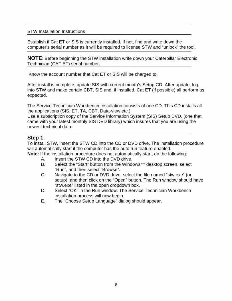
STW Installation Instructions Establish if Cat ET or SIS is currently installed. If not, find and write down the computer’s serial number as it will be required to license STW and “unlock” the tool. NOTE: Before beginning the STW installation write down your Caterpillar Electronic Technician (CAT ET) serial number. Know the account number that Cat ET or SIS will be charged to. After install is complete, update SIS with current month’s Setup CD. After update, log into STW and make certain CBT, SIS and, if installed, Cat ET (if possible) all perform as expected. The Service Technician Workbench Installation consists of one CD. This CD installs all the applications (SIS, ET, TA, CBT, Data-view etc.). Use a subscription copy of the Service Information System (SIS) Setup DVD, (one that came with your latest monthly SIS DVD library) which insures that you are using the newest technical data. Step 1. To install STW, insert the STW CD into the CD or DVD drive. The installation procedure will automatically start if the computer has the auto run feature enabled. Note: If the installation procedure does not automatically start, do the following:
A. Insert the STW CD into the DVD drive. B. Select the “Start” button from the Windows™ desktop screen, select
“Run”, and then select “Browse”. C. Navigate to the CD or DVD drive, select the file named “stw.exe” (or
setup), and then click on the “Open” button. The Run window should have “stw.exe” listed in the open dropdown box.
D. Select “OK” in the Run window. The Service Technician Workbench installation process will now begin.
E. The “Choose Setup Language” dialog should appear.
8
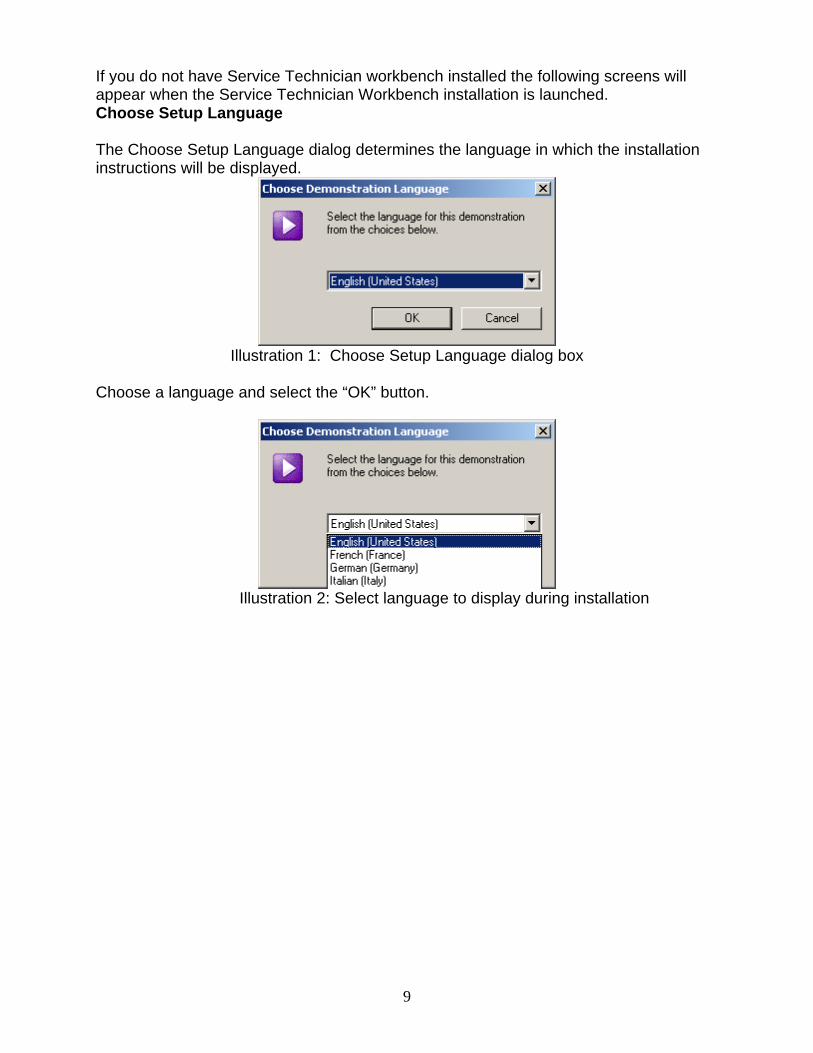
If you do not have Service Technician workbench installed the following screens will appear when the Service Technician Workbench installation is launched. Choose Setup Language The Choose Setup Language dialog determines the language in which the installation instructions will be displayed.
Illustration 1: Choose Setup Language dialog box
Choose a language and select the “OK” button.
Illustration 2: Select language to display during installation
9
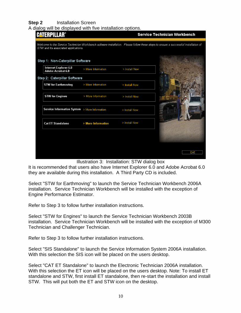
Step 2 Installation Screen A dialog will be displayed with five installation options.
Illustration 3: Installation: STW dialog box
It is recommended that users also have Internet Explorer 6.0 and Adobe Acrobat 6.0 they are available during this installation. A Third Party CD is included. Select "STW for Earthmoving" to launch the Service Technician Workbench 2006A installation. Service Technician Workbench will be installed with the exception of Engine Performance Estimator. Refer to Step 3 to follow further installation instructions. Select "STW for Engines" to launch the Service Technician Workbench 2003B installation. Service Technician Workbench will be installed with the exception of M300 Technician and Challenger Technician. Refer to Step 3 to follow further installation instructions. Select "SIS Standalone" to launch the Service Information System 2006A installation. With this selection the SIS icon will be placed on the users desktop. Select "CAT ET Standalone" to launch the Electronic Technician 2006A installation. With this selection the ET icon will be placed on the users desktop. Note: To install ET standalone and STW, first install ET standalone, then re-start the installation and install STW. This will put both the ET and STW icon on the desktop.
10
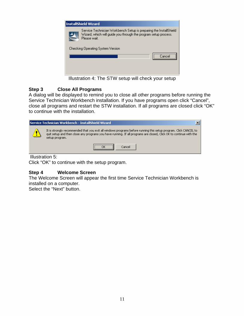
Illustration 4: The STW setup will check your setup
Step 3 Close All Programs A dialog will be displayed to remind you to close all other programs before running the Service Technician Workbench installation. If you have programs open click “Cancel”, close all programs and restart the STW installation. If all programs are closed click “OK” to continue with the installation.
Illustration 5: Click “OK” to continue with the setup program.
Step 4 Welcome Screen The Welcome Screen will appear the first time Service Technician Workbench is installed on a computer. Select the “Next” button.
11
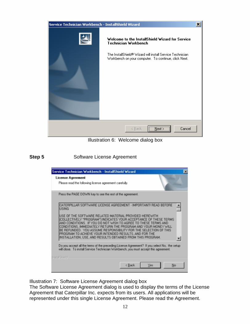
Illustration 6: Welcome dialog box
Step 5 Software License Agreement
Illustration 7: Software License Agreement dialog box The Software License Agreement dialog is used to display the terms of the License Agreement that Caterpillar Inc. expects from its users. All applications will be represented under this single License Agreement. Please read the Agreement.
12
Select the “Yes” button to continue. If you select the “No” button, your STW installation will terminate.
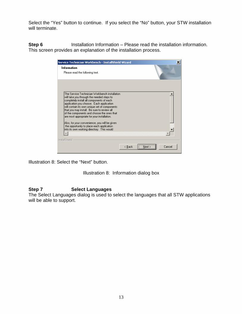
Step 6 Installation Information – Please read the installation information. This screen provides an explanation of the installation process.
Illustration 8: Select the “Next” button.
Illustration 8: Information dialog box Step 7 Select Languages The Select Languages dialog is used to select the languages that all STW applications will be able to support.
13
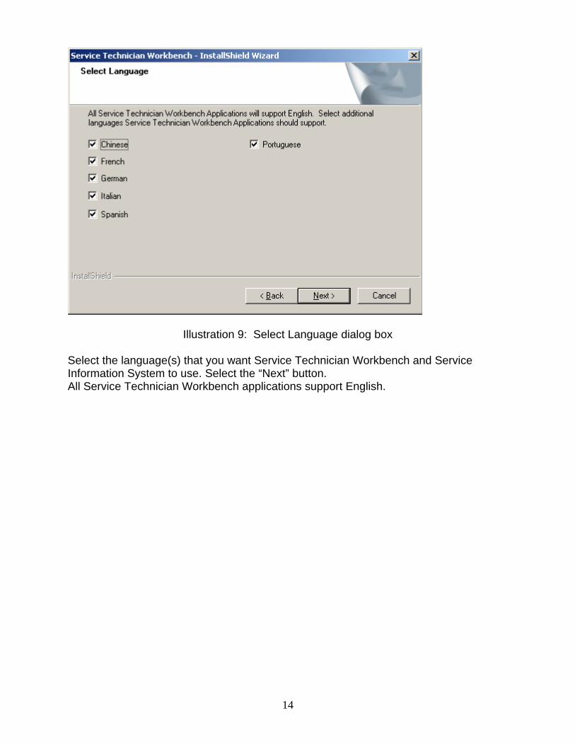
Illustration 9: Select Language dialog box
Select the language(s) that you want Service Technician Workbench and Service Information System to use. Select the “Next” button. All Service Technician Workbench applications support English.
14
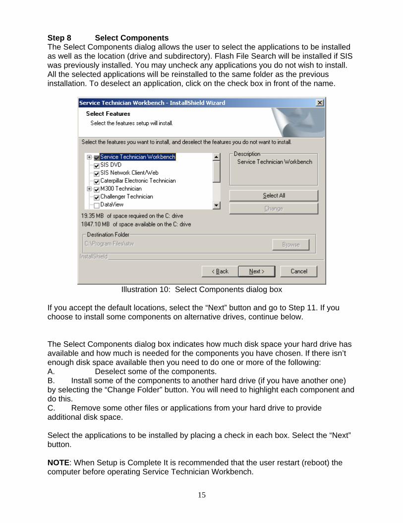
Step 8 Select Components The Select Components dialog allows the user to select the applications to be installed as well as the location (drive and subdirectory). Flash File Search will be installed if SIS was previously installed. You may uncheck any applications you do not wish to install. All the selected applications will be reinstalled to the same folder as the previous installation. To deselect an application, click on the check box in front of the name.
Illustration 10: Select Components dialog box
If you accept the default locations, select the “Next” button and go to Step 11. If you choose to install some components on alternative drives, continue below. The Select Components dialog box indicates how much disk space your hard drive has available and how much is needed for the components you have chosen. If there isn’t enough disk space available then you need to do one or more of the following: A. Deselect some of the components. B. Install some of the components to another hard drive (if you have another one) by selecting the “Change Folder” button. You will need to highlight each component and do this. C. Remove some other files or applications from your hard drive to provide additional disk space. Select the applications to be installed by placing a check in each box. Select the “Next” button. NOTE: When Setup is Complete It is recommended that the user restart (reboot) the computer before operating Service Technician Workbench.
15
16
This section will describe the recommended steps necessary to uninstall the Service Technician Workbench applications. To uninstall the software a user must use the STW Installation CD. The STW Installation CD is the only recommended method of uninstalling STW. Uninstalling Using the Installation CD Step 1 To uninstall STW, insert the STW CD into the CD or DVD drive. The installation procedure will automatically start if the computer has the autorun feature enabled. Skip ahead to Step 2. If the installation procedure does not automatically start, do the following: A. Insert the STW CD into the CD or DVD drive. B. Select the “Start” button from the Windows™ desktop screen, select “Run”, and then select “Browse.” C. Navigate to the CD or DVD drive, select the file named “stw.exe” (or setup), and then click on the “Open” button. The “Run” window should have stw.exe listed in the open dropdown box. D. Select the “OK” button in the Run window. The Service Technician Workbench installation process will now begin. E. The Choose Setup Language dialog should appear. Step 2 Choose Setup Language The Choose Setup Language dialog determines the language in which the installation instructions will be displayed. It does not determine which languages will be installed for Service Technician Workbench. Step 3 Select “Remove All…” from the Installation dialog. Step 4 A verification dialog will verify you want to uninstall STW. Select “Yes.” Step 5 The progress indicator will display what is being uninstalled. Step 6 If SIS was installed, the SIS installation will start.
17
Frequently Asked Questions If you are having a problem installing or using your software, here are some tips to get you started! First, please make sure you have thoroughly read the Getting Started section of this booklet. If you have followed the directions and are still having trouble installing or operating the software, here are some frequently asked questions and solutions that might help solve your problem. Q) Why is there no longer a SIS icon on the desktop after installing STW? A) The SIS icon is removed when STW is installed because SIS is now accessed
through STW. Q) Cat ET was licensed on my PC, but the license did not transfer after I installed
STW? A) On most PC'S the Cat ET license transfers automatically to STW. Use on-line
licensing at https://on-linelicensing.cat.com./ Q) Are TCP/IP and Dial-up Networking needed for STW and SIS to communicate? A) TCP/IP and Dial-up Networking are not needed for STW to communicate with
SIS. They are needed for SIS to communicate with Service Advisor or DBS through Parts Integrator. TCP/IP and Dial-up Networking are also needed to send and receive Feedback from STW.
Q) How do I access SIS Web through STW? A) Click on the same icon in the STW launch pad that you would to access SIS
Windows. There is a preference setting in STW that indicates which application should launch. In STW Select View > Preferences and then select the SIS tab. Select SIS WEB. You must restart STW before the setting will take affect.
Q) Why do I have to sign into SIS Web even though I’ve already signed into STW? A) The STW and SIS Web users exist independently of each other. Your SIS Web user is based on your Corporate Web Security (CWS) ID. To get through Caterpillar’s internet security, you will still need to sign in using your CWS ID and password which is not currently tied to the STW users created on your machine. Q) Why do M300 Technician, Challenger Technician, and DataView launch over the top of STW in their own window, Cat ET, SIS DVD, SIS Web, CBT, run within the STW window? A) These applications are not integrated with STW and launch outside of the STW container. Q) How do I get a SIS Web account? A) Talk to the SIS Coordinator or SIS Administrator at your dealership. He/She should be able to help you get a CWS user ID and then give you access to SIS Web. If your SIS Coordinator has questions, have them contact the DCS support center at 800-765-0999 or [email protected]. Q) Why won’t my old SIS library work with STW? A) If your SIS library is pre-May 2006, You will need to have a new SIS library version. May 2006 or later. You can get this by calling your SIS Coordinator.
18
Q) How do I send Feedback? A) Click on the Feedback icon (first icon on tool bar) and answer questions. - If you are connected to your dealer network, click on the “Send/Receive” button. - If you are not connected to a network, then click on “Export” and then “Feedback to Caterpillar” and save it on a floppy. - If you get a message that you were not able to transmit to the ftp.cat.com connection, then contact your Information Systems (IS) department. Your dealership’s firewall may be preventing you from sending Feedback. Your IS contact can contact the Help Desk (Service Systems Support Center) for help on this issue. The DCS Support Center’s contact information is near the end of this document. Q) How is SIS Web feedback different from STW feedback? A) All feedback comes into the DCS support center. Feedback from SIS Web will record the page that you were on when you selected to send feedback. In a similar way, STW feedback will record what you were doing in the application you were in when you selected to send feedback. Sending feedback from the appropriate application will help first and second level support correctly diagnose the issue or assign it to the appropriate team. Q) Why is Internet Explorer 6.0 (IE 5.5) required for the Service Technician Workbench to operate? A) STW requires IE 6.0 or higher for the STW Report Utility. Q) Why does the SIS user name and password have to be the same as the STW
user name and password? A) Using the same password allows the user to sign in just one time in order to use
all the STW tools. Q) Why are there two different user administration tools? Why can't SIS and STW
use the same user administration tool? A) These programs will continue to be improved. We are in the process of
integrating the two software packages. A single user administration tool is planned for a future release of Workbench. We’ll keep you updated.
Q) Why is Flash File Search (FFS) not working with Network SIS on my computer? A) If you installed May SIS Setup CD to use SIS CD’s/DVD’s, FFS is installed on
your PC Hard Disk Drive. If you now decide to point SIS to Network data, install the May SIS Network Setup CD to enable FFS to work with Network SIS.
Q) Why isn’t the FFS icon on the launchpad? A) FFS icon is not displayed when the SIS preference is set to SIS Web. You must
change the SIS preference settings to SIS DVD.
19
Q) How do I subscribe to SIS and/or Cat ET? A) It’s simple! Contact Caterpillar Media and Product Information Logistics at https://on-linelicensing.cat.com. You may also e-mail: [email protected]. Q) What do I need to do if I get a new computer? A) With your old computer, first export Bookmarks to a floppy or network drive. Next, copy Service Reports that are in the .pdf and .xml formats to a floppy or network drive (default location is Program Files/STW/STW/Rptfile).
When the new computer is in place, make certain STW has been installed. Go into the STW User Administration, which is on the desktop, and populate as much information as possible. Doing so will allow some of this same information to be populated when generating Feedback or a Service Report. If STW is installed, log into STW and import the Feedback and Bookmarks from floppy or network drive. Next you will need to Transfer the license to the new computer after STW is installed. Go to: https://on-linelicensing.cat.com or contact your SIS coordinator to transfer the license. Make certain that STW is working as expected on the NEW pc. Uninstall STW from old PC to prevent any unauthorized usage. Q) How do I receive responses to “Feedback”? A) Click the “Feedback” icon then click “Send/Receive”. This button is used to both send and receive “Feedback” communication. If you have received a “Feedback” response then you will have a dialog box with instructions on viewing or saving the response. Q) Why does the Feedback feature not work? A) STW uses the internet to send the Feedback to Caterpillar. Make sure the computer’s modem is properly configured. Go to your computer desktop, then to Start/Settings/Control Panel. Highlight “Network/TCP/IP -> Dial-Up Adapter” and choose Properties/DNS Configuration/Enable DNS. Then contact your IS department to obtain your “Host” and “Domain Suffix Search Order” and enter these in the appropriate boxes and click “OK”. Restart your computer when prompted. If you are still having problems, refer to the previous questions and answers related to sending and receiving Feedback. Q) How do I save a completed Service Report? A) The STW user now has the choice to save the Service Report in either the .xml
format or .pdf format. The Adobe .pdf should be used only if the service report does not need to be updated. The .xml format should be used to allow update and share with the office administrators. To save a service report click the “Save” icon on the STW tool bar
Q) How do I open a completed Service Report? A) The service report must be saved using the .xml format to open in STW. Select
File>Session>From Report to open a service report back into the STW session.

20
Q) How can I have the logo for my dealership appear in the top right hand corner of the STW Service Report?
A) First, find the image you want and name it “dealer.jpg”. Next, copy the file into: “C:\Program Files\Caterpillar Inc\Service Report\Themes\Logos”. Restart STW and the next time an STW Service Report is generated your image will be in the top right hand corner. Q) Why aren’t my digital images, Cat ET reports, or Cat ET graphics being displayed in the STW Service Report? A) Launch the STW Service Report and choose View, Preferences from the menu. The Service Report Preference tab will be displayed. Verify that the checkboxes for Digital Images is selected.
21
Purpose If communicating Service Information System (SIS) with DBS through Parts Integrator or SIS with Service Advisor, then a computer protocol named TCP/IP needs to be installed on your PC. Sending and receiving Feedback using STW also requires the computer protocol TCP/IP. If SIS does not communicate with DBS through Parts Integrator or Service Advisor, then follow the instructions below to resolve the problem. Also refer to the following instructions if you are unable to send or receive Feedback in STW. Step 1 Installing Dial-up Networking Windows™ 2000: A. Double click the “My Computer” icon on your desktop. B. In “My Computer”, double click the “Control Panel” icon. C. In the “Control Panel”, choose “Network” and “Dial-Up Connections”. D. Choose “Local Area Connection Status”. E. Click on “Properties” and choose “Install”. F. Select “Protocol: and then the “Add...” button. G. Choose “TCP/IP” from the list. H. Installation will proceed. I. After the installation has completed, restart your computer. Windows™ XP: TCP/IP is automatically installed with Windows™ XP. Step 3 If communicating between SIS and DBS through Parts Integrator, then try to use it. If communicating between SIS and Service Advisor, then try to use it. If sending and receiving Feedback in STW, then try to use it. Contact the DCS Support Center if you continue to have problems. The DCS Support Center’s contact information is near the end of this document.
22
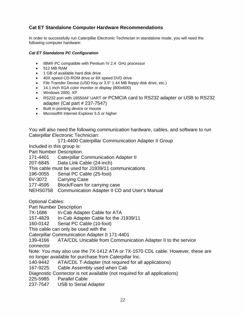
Cat ET Standalone Computer Hardware Recommendations
In order to successfully run Caterpillar Electronic Technician in standalone mode, you will need the following computer hardware:
Cat ET Standalone PC Configuration
• IBM® PC compatible with Pentium IV 2.4 GHz processor • 512 MB RAM • 1 GB of available hard disk drive • 40X speed CD-ROM drive or 8X speed DVD drive • File Transfer Devise (USD Key or 3.5" 1.44 MB floppy disk drive, etc.) • 14.1 inch XGA color monitor or display (800x600) • Windows 2000, XP • RS232 port with 16550AF UART or PCMCIA card to RS232 adapter or USB to RS232
adapter (Cat part # 237-7547) • Built in pointing device or mouse • Microsoft® Internet Explorer 5.5 or higher
You will also need the following communication hardware, cables, and software to run Caterpillar Electronic Technician: 171-4400 Caterpillar Communication Adapter II Group Included in this group is: Part Number Description 171-4401 Caterpillar Communication Adapter II 207-6845 Data Link Cable (24-inch) This cable must be used for J1939/11 communications 196-0055 Serial PC Cable (25-foot) 6V-3072 Carrying Case 177-4595 Block/Foam for carrying case NEHS0758 Communication Adapter II CD and User’s Manual Optional Cables: Part Number Description 7X-1686 In-Cab Adapter Cable for ATA 157-4829 In-Cab Adapter Cable for the J1939/11 160-0142 Serial PC Cable (10-foot) This cable can only be used with the Caterpillar Communication Adapter II 171-4401 139-4166 ATA/CDL Unicable from Communication Adapter II to the service connector Note: You may also use the 7X-1412 ATA or 7X-1570 CDL cable. However, these are no longer available for purchase from Caterpillar Inc. 140-9442 ATA/CDL T-Adapter (not required for all applications) 167-9225 Cable Assembly used when Cab Diagnostic Connector is not available (not required for all applications) 225-5985 Parallel Cable 237-7547 USB to Serial Adapter
23
- OR - 7X-1700 - Caterpillar Communication Adapter Group Also requires: Part Number Description NEXG4523 Communication Adapter Software SPM (Service Program Module) Version 1.2 or greater 7X-1425 RS232 Serial PC Cable This cable can only be used with the Caterpillar Communication Adapter 7X-1701 139-4166 ATA/CDL Unicable from Communication Adapter II to the service connector Note: You may also use the 7X-1412 ATA or 7X-1570 CDL cable. However, these are no longer available for purchase from Caterpillar Inc. 140-9442 ATA/CDL T-Adapter (not required for all applications) - OR - MPSI Pro-Link® 9000 (only for On Highway Truck engines and certain commercial applications). Also requires: Description MPSI PC/Terminal Cable MPSI Caterpillar Cartridge (version 1.07 or greater) Exceptions: The requirements for Challenger Technician (CT), M300 Technician (M300), and Hydraulic Excavators are: CT 1U-9100 Cable Assembly - Challenger to PC Adapter cable M300 126-7877 Cable Assembly - M300 to PC Adapter cable HEX: 127-9797 Cable Assembly - HEX to PC Adapter cable Requirements 171-4400 - Caterpillar Communication Adapter II Group Included in this group is the following equipment: Part Number Description 171-4401 Caterpillar Communication Adapter II 207-6845 Data Link Cable (24-inch) This cable must be used for J1939/11 communications 196-0055 Serial PC Cable (25-foot) 6V-3072 Carrying Case 177-4595 Block/Foam for carrying case NEHS0758 Communication Adapter II CD-ROM and User’s Manual Optional Cables: Part Number Description 7X-1686 In-Cab Adapter Cable for ATA
24
157-4829 In-Cab Adapter Cable for the J1939/11 160-0142 Serial PC Cable (10-foot) This cable can only be used with the Caterpillar Communiction Adapter II 171-4401 139-4166 ADA/CDL Unicable from a Caterpillar communication adapter to the service connector Note: You may also use the 7X1412 ATA or 7X1570 CDL cable. However, these are no longer available for purchase from Caterpillar Inc. 140-9442 ATA/CDL T-Adapter (not required for all applications) 167-9225 Cable Assembly used to connect your service tool directly to the ECM Instructions To connect the Communication Adapter II to the PC, perform the following steps: Step 1 Align and attach one end of the serial cable to the PC cable connection on the Communication Adapter II. Step 2 Connect the other end of the cable to the serial port of your PC. To connect the Communication Adapter II to the data link, perform the following steps: Step 1 After you have connected the Communication Adapter II to your PC, connect one end of the data link cable to the data link connection on the Communication Adapter II. Step 2 Connect the other end of the data link cable to the service connector on the product you wish to test. If the data link is powered (machine power is on), the Power light on the Communication Adapter will glow and the diagnostic test will begin. The lights on the front of the Communication Adapter II will sequentially glow from the bottom to the top of the device. You are now ready to start the service tool. Requirements 7X1700 - Caterpillar Communication Adapter Group Also requires: Part Number Description NEXG4523 Communication Adapter Software SPM (Service Program Module) Version 1.2 or greater 7X-1425 RS232 Serial PC Cable This cable can only be used with the Caterpillar Communication Adapter 7X1701 139-4166 ATA/CDL Unicable from a Caterpillar communication adapter to the service connector Note: You may also use the 7X1412 ATA or 7X1570 CDL cable. However, these are no longer available for purchase from Caterpillar Inc. 140-9442 ADA/CDL T-Adapter (not required for all applications) 167-9225 Cable Assembly used to connect your service tool directly to the ECM
25
Instructions To set up the Communication Adapter, perform the following steps: Step 1 Connect the 7X-1425 RS232 cable to an available COM Port on your PC and to the Service Tool connector on the Communication Adapter. Step 2 Connect the 139-4166 Unicable to the Control connector on the Communication Adapter and to the service connector on the product that you are servicing. You are now ready to start your service tool. Requirements MPSI Pro-Link® 9000 (only for On Highway Truck engines and certain commercial applications). This package also requires the following equipment: Description MPSI PC/Terminal Cable MPSI Caterpillar Cartridge (version 1.07 or greater) Instructions Perform the following steps to set up the Pro-Link® 9000: Step 1 Insert the MPSI Caterpillar Cartridge in the Pro-Link® 9000. Step 2 Connect the Pro-Link® 9000 to your PC's serial port using the MPSI PC/Terminal cable. Step 3 Connect the Pro-Link® 9000 to the product and turn the ignition key of the vehicle on to power the Pro-Link. Step 4 Select Pro-Link from the main menu or push the "Func" key to recall data if no engine data is received. Step 5 Select the Com Adapter Link function from the Pro-Link menu, and push "Enter" to initiate the Com Adapter Link mode. The Pro-Link will display a screen showing that the Com Adapter Link is active. You are now ready to start the service tool. See Installing STW on page 10 of this manual. Purpose Trainer runs the service tool in a training mode. This allows you to become familiar with the service tool without needing to be connected to an Electronic Control Module (ECM) or Communications Adapter. There is no charge for Trainer, and authorization is not required. Illustration 30: Trainer menu functions Instructions Using Trainer: Step 1 Select Caterpillar ET from the Programs menu, and then select Electronic Technician from the submenu. The Connection message box is displayed. Connection message box Step 2 Press the "Stop Connect" pushbutton. The service tool main screen is displayed.
26
Step 3 Select Trainer from the Help menu, and then select Enable from the submenu, or push the Enable Trainer icon on the toolbar (if default is set). The Trainer dialog box is displayed. Trainer dialog box Step 4 Select a product from the Application drop-down list. Step 5 Press "OK." The Connection message box is displayed. The ECM Summary screen displays in the trainer mode (Refer to Illustration 33). Trainer simulates some of the service tool functions. Press "Cancel" to exit Trainer. You will return to the service tool main screen. Trainer screen To change the product simulated within Trainer: Step 1 Select Trainer from the Help menu, and then select Properties from the submenu. The Trainer dialog box is displayed. Step 2 Select a different product from the Application drop-down list. Step 3 Press "OK." The Connection message box is displayed. Then the new product is displayed. To exit Trainer: Select Trainer from the Help menu, and then select Disable on the submenu, or push the Disable Trainer icon from the toolbar (if default is set). Purpose What's New allows you to view a list of new functions and major enhancements available in the installed version of the service tool. What's New launches your browser when it is selected from the Help drop down. What's New is displayed in the language selected as default in the Select Default Language dialog box during the installation of your service tool. If an Internet browser is not installed on the PC, What's New is displayed in *.txt format. What’s New screen using a browser Instructions To view the What's New screen, select What's New from the Help menu Power Management Turn off Power Management (for example a screen saver or "sleep" mode) when using your service tool. Communication to the ECM might be interrupted if the PC "suspends." Infrared Communication Problems If your computer supports infrared communication, you may experience some communication problems with the service tool. It is recommended that you disable the infrared option. If you need help with this procedure, please contact the computer manufacturer. Disk Defragmentation/Disk Compression
27
The service tool will remain unaffected by Disk Compression and/or Defragmentation programs as long as the compression/defragmentation programs do not move hidden or system files during the process. Windows™ 2000, and XP Installation Administrative rights are required to install Cat ET for the first time. Most upgrades do not require administrative rights. Error Code LIC0102 The Windows (tm) driver appears not to be serving this directory. The CrypKey License service is not started, or the service is not protecting the Cat ET directory. To determine if the CrypKey License service is started, select Services from the Control Panel (in Windows(tm) 2000, select Administrative Tools from the Control Panel), then select services. CrypKey License should appear in the service list. If the CrypKey License service is not started, then the service needs to be started. If it is not there, then re-install the service tool. Note: The user must have administrative rights to add a directory. To start the service: Run the SETUP_CK.EXE program located in the windows directory (i.e. C:\WINDOWS\ ). Once the CrypKey License service is started, it automatically starts every time the system starts (Any user can then log in and use the CrypKey License service.). If the CrypKey License service is running and you still get the LIC0102 error code, then the problem may be that the service tool path is not protected. Run the CKCONFIG.EXE program located in the Windows (tm) directory (i.e. C:\WINDOWS\ ). The service tool directory must be listed in the CrypKey NT Server Configure window. If it is not, it must be added. To add the service tool directory, do the following: Press the "Add" pushbutton. The Open dialog box is displayed. Choose ETECH.EXE in the service tool directory (i.e. C:\Program Files\Caterpillar Electronic Technician\), and press "OK." Press the "Close" pushbutton. If you get an "Internal Error Open SC Manager" failure when the CrypKey NT Server Configure program was closed, you may not have Administrator privileges. Therefore, the CrypKey License server was not updated. Selecting the Correct Port Select Preferences… on the Utilities menu. The Preferences dialog box is displayed. Select the Communications tab. Laptops: If you use the built-in pointing device on your laptop PC, your first available port is usually COM 1. Personal Computer (PC): If your PC has a mouse with a round plug, your first available port is usually COM 1. If your PC has a mouse that DOES NOT have a round plug, your first available port is usually COM 2. If your PC DOES NOT have a mouse, your first available port is usually COM 1. Communication Errors Two types of error messages display when communication problems occur. Understanding these messages can help you correct the situation.
28
"Unable to Communicate with an ECM!" This is a problem between the communication interface device and the ECM. The PC did detect the communication interface device. Make sure all connections between the communication interface device and the ECM are secure and intact. If the error displays again, verify that you are using the correct cables for your application. A. Check all connections between the PC and the ECM. B. Verify that you are using the correct cables for your application. C. Verify that the ECM has power. "Unable to Communicate with the Caterpillar Communication Adapter!" This error refers to a problem between the PC and the Communication Adapter. D. Check all connections between the PC and the ECM. E. Check that the Communication Adapter is receiving external power. The product being serviced must have the key switch on for power, unless it is connected directly to a battery. F. Verify in Preferences, under the Settings menu, that the correct port is selected. G. Verify in Preferences, under the Settings menu, that the correct Communication Interface Device is selected. H. If the error displays again, verify that you are using the correct cables for your application. I. Verify that your PC Comm Port is set up correctly and is not in use by another device (for example Palm Pilot Software). Try using another Comm Port, if it is available. Caterpillar Communication Adapter II Error Codes: When calling for software support, report the error code number to the support staff member. This will aid in solving the communication problem. The chart below is a list of error codes and the possible solutions to those errors. Error Code Error Description Suggestion --- No initialization file present. Un-install and re-install the Cat Comm Adapter II software. Make sure you reboot the PC after the installation is complete. --- Unable to read Cat Communication Adapter (RP1210) Initialization File. If the PC has Cat Comm Adapter II software installed, try rebooting the PC first. If this does not cure the problem, re-install the Cat Comm Adapter II software. Make sure you reboot the PC after the installation is complete. --- Unable to load CA2RP32.DLL If the PC has Cat Comm Adapter II software installed, try rebooting the PC first. If this does not cure the problem, re-install the Cat Comm Adapter II software. Make sure you reboot the PC after the installation is complete. 142* The interface hardware is not connected. Check the cables. Make sure the data link cable and serial communication cables are properly connected. Verify the Cat Comm Adapter II "Power" light is on. Check that Caterpillar Electronic Technician is configured for the correct communications port.
29
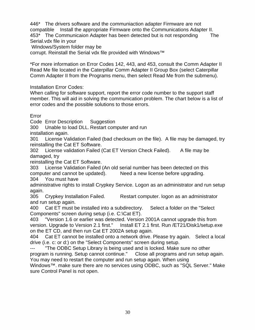
202 A required INI file was not located. Un-install and then re-install the Cat Comm Adapter II software. Make sure you reboot the PC after the installation is complete. 204 A required INI file section was not found. Un-install and then re-install the Cat Comm Adapter II software. Make sure you reboot the PC after the installation is complete. 205 A necessary INI file key was not found. Un-install and re-install the Cat Comm Adapter II software. Make sure you reboot the PC after the installation is complete. 206 An INI file value was invalid Un-install and then re-install the Cat Comm Adapter II software. Make sure you reboot the PC after the installation is complete. 230 Port not open Another program or device is currently using the com port or the com port's resources. Identify the source and remove or disable it. Palm Pilot software commonly causes this error. 231 Invalid Comm Port The selected comm port is not set up properly in the PC's BIOS or operating system. 300 A device driver could not be opened. Un-install and then re-install the Cat Comm Adapter II software. Make sure you reboot the PC after the installation is complete. 301 Cannot open the configuration file. Un-install and then re-install the Cat Comm Adapter II software. Make sure you reboot the PC after the installation is complete. 302 The session identifier was not found in the configuration file. Un-install and then re-install the Cat Comm Adapter II software. Make sure you reboot the PC after the installation is complete. 303 An error was found in the configuration file format. Un-install and then re-install the Cat Comm Adapter II software. Make sure you reboot the PC after the installation is complete. 308 A 16-bit client application is trying to use the Comm Adapter II, but the APISRV32.EXE file is missing or not in the default Windows™ directory. This only applies to Windows™ 95/98. Re-install the Comm Adapter II software. Make sure you reboot the PC after the installation is complete. 405 The PC had a problem while trying to establish the communication baud rate with the Comm Adapter II. Power cycle the Comm Adapter II and reboot the PC. If the error persists, lower the communication baud rate. 406 The PC tried to establish a connection to the Comm Adapter II, but ran into a problem during the communication initialization phase. This error code occurs during the communication initialization phase when the specific stage is not identified. Error codes 142, 405, 441, or 453 relate to specific stages in the initialization process. 441 The requested protocol is not compatible with an existing data link. Cycle the power on the Cat Comm Adapter II and ECM. If this does not correct the problem, reboot the PC, and try again. Do not launch the Comm Adapter II Toolkit while Cat ET is running.
30
446* The drivers software and the communiaction adapter Firmware are not compatible Install the appropriate Firmware onto the Communications Adapter II. 453* The Communicaion Adapter has been detected but is not responding The Serial.vdx file in your Windows/System folder may be corrupt. Reinstall the Serial vdx file provided with Windows™ *For more information on Error Codes 142, 443, and 453, consult the Comm Adapter II Read Me file located in the Caterpillar Comm Adapter II Group Box (select Caterpillar Comm Adapter II from the Programs menu, then select Read Me from the submenu). Installation Error Codes: When calling for software support, report the error code number to the support staff member. This will aid in solving the communication problem. The chart below is a list of error codes and the possible solutions to those errors. Error Code Error Description Suggestion 300 Unable to load DLL. Restart computer and run installation again. 301 License Validation Failed (bad checksum on the file). A file may be damaged, try reinstalling the Cat ET Software. 302 License validation Failed (Cat ET Version Check Failed). A file may be damaged, try reinstalling the Cat ET Software. 303 License Validation Failed (An old serial number has been detected on this computer and cannot be updated). Need a new license before upgrading. 304 You must have administrative rights to install Crypkey Service. Logon as an administrator and run setup again. 305 Crypkey Installation Failed. Restart computer. logon as an administrator and run setup again. 400 Cat ET must be installed into a subdirectory. Select a folder on the "Select Components" screen during setup (i.e. C:\Cat ET). 403 "Version 1.6 or earlier was detected. Version 2001A cannot upgrade this from version. Upgrade to Version 2.1 first." Install ET 2.1 first. Run /ET21/Disk1/setup.exe on the ET CD, and then run Cat ET 2002A setup again. 404 Cat ET cannot be installed onto a network drive. Please try again. Select a local drive (i.e. c: or d:) on the "Select Components" screen during setup. --- "The ODBC Setup Library is being used and is locked. Make sure no other program is running. Setup cannot continue." Close all programs and run setup again. You may need to restart the computer and run setup again. When using Windows™. make sure there are no services using ODBC, such as "SQL Server." Make sure Control Panel is not open.
31
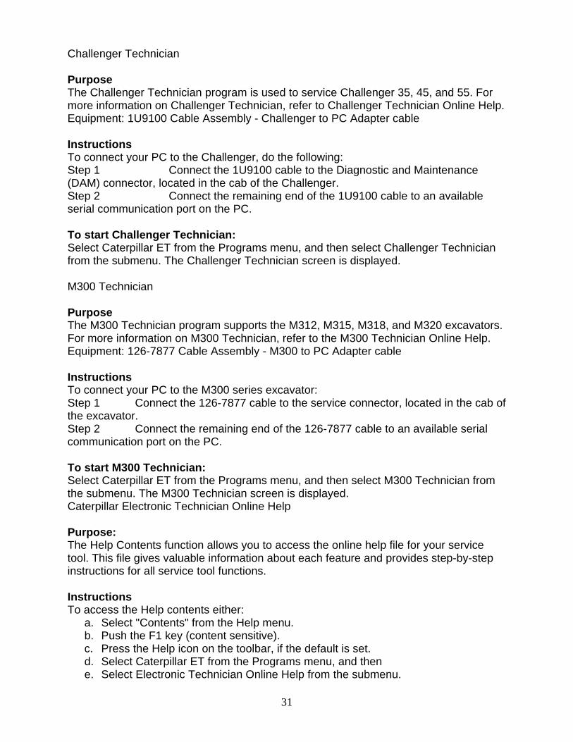
Challenger Technician Purpose The Challenger Technician program is used to service Challenger 35, 45, and 55. For more information on Challenger Technician, refer to Challenger Technician Online Help. Equipment: 1U9100 Cable Assembly - Challenger to PC Adapter cable Instructions To connect your PC to the Challenger, do the following: Step 1 Connect the 1U9100 cable to the Diagnostic and Maintenance (DAM) connector, located in the cab of the Challenger. Step 2 Connect the remaining end of the 1U9100 cable to an available serial communication port on the PC. To start Challenger Technician: Select Caterpillar ET from the Programs menu, and then select Challenger Technician from the submenu. The Challenger Technician screen is displayed. M300 Technician Purpose The M300 Technician program supports the M312, M315, M318, and M320 excavators. For more information on M300 Technician, refer to the M300 Technician Online Help. Equipment: 126-7877 Cable Assembly - M300 to PC Adapter cable Instructions To connect your PC to the M300 series excavator: Step 1 Connect the 126-7877 cable to the service connector, located in the cab of the excavator. Step 2 Connect the remaining end of the 126-7877 cable to an available serial communication port on the PC. To start M300 Technician: Select Caterpillar ET from the Programs menu, and then select M300 Technician from the submenu. The M300 Technician screen is displayed. Caterpillar Electronic Technician Online Help Purpose: The Help Contents function allows you to access the online help file for your service tool. This file gives valuable information about each feature and provides step-by-step instructions for all service tool functions. Instructions To access the Help contents either:
a. Select "Contents" from the Help menu. b. Push the F1 key (content sensitive). c. Press the Help icon on the toolbar, if the default is set. d. Select Caterpillar ET from the Programs menu, and then e. Select Electronic Technician Online Help from the submenu.
32
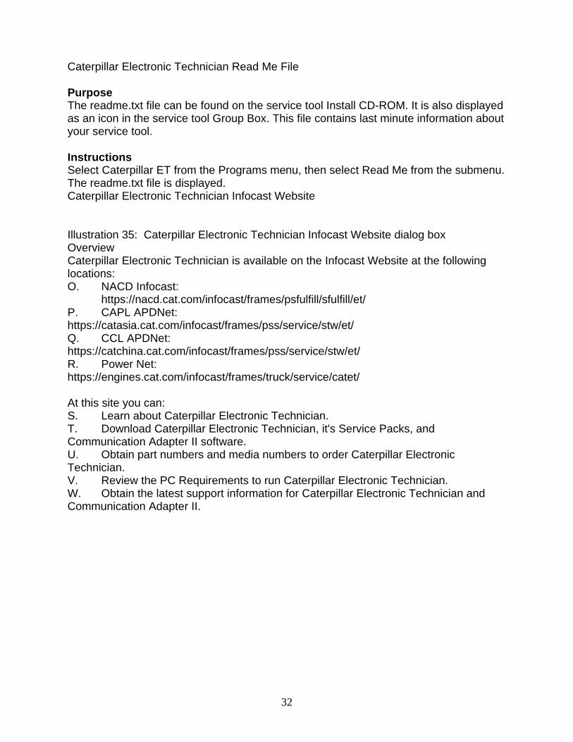
Caterpillar Electronic Technician Read Me File Purpose The readme.txt file can be found on the service tool Install CD-ROM. It is also displayed as an icon in the service tool Group Box. This file contains last minute information about your service tool. Instructions Select Caterpillar ET from the Programs menu, then select Read Me from the submenu. The readme.txt file is displayed. Caterpillar Electronic Technician Infocast Website Illustration 35: Caterpillar Electronic Technician Infocast Website dialog box Overview Caterpillar Electronic Technician is available on the Infocast Website at the following locations: O. NACD Infocast: https://nacd.cat.com/infocast/frames/psfulfill/sfulfill/et/ P. CAPL APDNet: https://catasia.cat.com/infocast/frames/pss/service/stw/et/ Q. CCL APDNet: https://catchina.cat.com/infocast/frames/pss/service/stw/et/ R. Power Net: https://engines.cat.com/infocast/frames/truck/service/catet/ At this site you can: S. Learn about Caterpillar Electronic Technician. T. Download Caterpillar Electronic Technician, it's Service Packs, and Communication Adapter II software. U. Obtain part numbers and media numbers to order Caterpillar Electronic Technician. V. Review the PC Requirements to run Caterpillar Electronic Technician. W. Obtain the latest support information for Caterpillar Electronic Technician and Communication Adapter II.
33
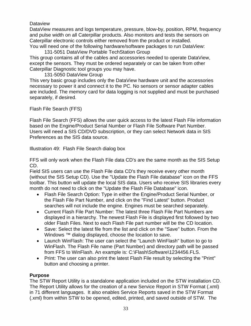
Dataview DataView measures and logs temperature, pressure, blow-by, position, RPM, frequency and pulse width on all Caterpillar products. Also monitors and tests the sensors on Caterpillar electronic controls either removed from the product or installed. You will need one of the following hardware/software packages to run DataView: 131-5051 DataView Portable TechStation Group This group contains all of the cables and accessories needed to operate DataView, except the sensors. They must be ordered separately or can be taken from other Caterpillar Diagnostic tool groups you may have. 131-5050 DataView Group This very basic group includes only the DataView hardware unit and the accessories necessary to power it and connect it to the PC. No sensors or sensor adapter cables are included. The memory card for data logging is not supplied and must be purchased separately, if desired. Flash File Search (FFS) Flash File Search (FFS) allows the user quick access to the latest Flash File information based on the Engine/Product Serial Number or Flash File Software Part Number. Users will need a SIS CD/DVD subscription, or they can select Network data in SIS Preferences as the SIS data source. Illustration 49: Flash File Search dialog box FFS will only work when the Flash File data CD's are the same month as the SIS Setup CD. Field SIS users can use the Flash File data CD's they receive every other month (without the SIS Setup CD). Use the "Update the Flash File database" icon on the FFS toolbar. This button will update the local SIS data. Users who receive SIS libraries every month do not need to click on the "Update the Flash File Database" icon.
• Flash File Search Option: Type in either the Engine/Product Serial Number, or the Flash File Part Number, and click on the "Find Latest" button. Product searches will not include the engine. Engines must be searched separately.
• Current Flash File Part Number: The latest three Flash File Part Numbers are displayed in a hierarchy. The newest Flash File is displayed first followed by two older Flash Files. Next to each Flash File part number will be the CD location.
• Save: Select the latest file from the list and click on the "Save" button. From the Windows ™ dialog displayed, choose the location to save.
• Launch WinFlash: The user can select the "Launch WinFlash" button to go to WinFlash. The Flash File name (Part Number) and directory path will be passed from FFS to WinFlash. An example is: C:\Flash\Software\1234456.FLS.
• Print: The user can also print the latest Flash File result by selecting the "Print" button and choosing a printer.
Purpose The STW Report Utility is a standalone application included on the STW installation CD. The Report Utility allows for the creation of a new Service Report in STW Format (.xml) in 71 different languages. It also enables Service Reports saved in the STW Format (.xml) from within STW to be opened, edited, printed, and saved outside of STW. The
34
STW Report Utility is for dealer personnel, such as clerks, who need to view, edit and print a service technician's Service Reports. The STW Report Utility is installed when STW is installed, but can be installed separately and used on a PC without STW. Installation
A. Insert the STW CD into the PC's CD or DVD drive. B. Use "My Computer" or "Windows Explorer" to locate the folder titled "Report
Utility”. Open this folder and double click on "Setup.exe". C. "Setup.exe" will install the STW Report Utility on the hard drive and also create a
shortcut on the PC's desktop. Operation Double click on the STW Report Utility's shortcut icon on the desktop to launch the Report Utility. A blank Service Report will be displayed along with menu options and a toolbar.
• To Create a New Service Report: Choose New from the File menu or click on the New icon in the toolbar.
• To Open an Existing Service Report Saved in STW Format (.xml): Choose File, Open from the menu or click on the Open icon in the toolbar.
• To Preview or Print a Service Report: Choose Print Preview or Print from the File menu or click on the Print Preview or Print icons in the toolbar.
• To Save a Service Report: Choose Save from the File menu or click on the Save icon in the toolbar.
File Menu • To Cut, Copy, or Paste Text: Choose Cut, Copy, or Paste from the Edit menu or click on the Cut, Copy, or Paste icons in the toolbar. Edit Menu • To Change the Language Settings: Choose Language Preferences from the View menu. View Menu • To Access Help: Select Help from the menu or click on the Help icon in the toolbar. Help Menu • To Add Lines to a Particular Section of the Service Report: Click on the Add Line button for that section.
35
• To Delete Existing Lines from a Particular Section of the Service Report: Click on the Delete Line button for that section. Those lines with checkmarks next to them will be removed. DBS Labor Entry and Approval Setup DBS Reference document: Adding Labor – DBS Chapter 6 or Direct Labor Approval – DBS Chapter 6 DBS must be setup to approve labor before labor is uploaded using the SIMS DBS utility. Approval is required for all labor that is uploaded to DBS using the SIMS DBS upload utility. The list of commands that follow is required to setup and approve labor in the DBS system. When the initial setup is complete, the approver will use the MNTWOAPPV screen to approve labor. The technician uploading labor to DBS will not need additional DBS access to complete the labor upload. Access to DBS Screens Needed to Setup the STW Labor Upload The screens listed below are required to setup direct labor approval within DBS. The person setting up this functionality should check to see if they are permitted access to each of the screens that follow before beginning the labor approval setup process. If necessary, make a list of the screens below that the setup person cannot access and then call the DBS person responsible for granting access to these screens. This will eliminate the need to call the DBS administrator numerous times. MNTWOCTL (Direct Labor to Approval Indicator) The direct labor to approval indicator must be set to YES to enable labor to be uploaded through the SIMS/DBS upload utility. Uploaded labor through the STW upload utility requires approval. MNTWOAPR (Approver Maintenance) Setup the persons responsible for approving labor with this screen. MNTWOSHF (Work Day Maintenance) The workday (hours) for the employee is setup and assigned a code. Each technician will be assigned a workday code within the MNTWOEMP@ screen. MNTWOEMP2 (Empl. Maint.-Lbr Collection) (Employee cross reference) The employee ID, approver group and workday code will be entered in this area to permit the employee to enter and upload labor to DBS. MNTWOEMP (Employee Function) Maintain the employee’s personal information with this screen. MNTWOAPPV (Accept labor entries) The people responsible for approving labor will use this screen to review and approve labor. DSPWOEMP (Employee Inquiry) Obtain work order information from this screen. (Not discussed in this document. Refer to the DBS reference document listed earlier.) LSTWOARCH (Archive Labor Audit) Manage or archive information from this DBS screen (Not discussed in this document. Refer to the DBS reference document listed earlier.)
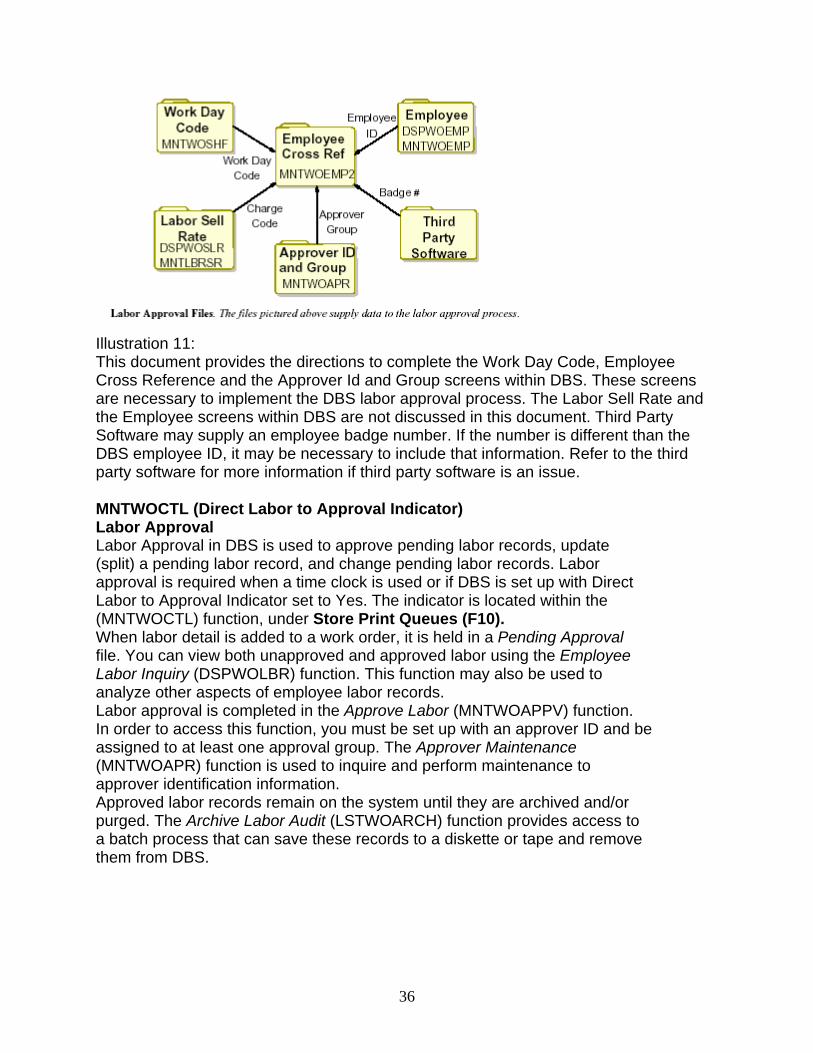
Illustration 11: This document provides the directions to complete the Work Day Code, Employee Cross Reference and the Approver Id and Group screens within DBS. These screens are necessary to implement the DBS labor approval process. The Labor Sell Rate and the Employee screens within DBS are not discussed in this document. Third Party Software may supply an employee badge number. If the number is different than the DBS employee ID, it may be necessary to include that information. Refer to the third party software for more information if third party software is an issue. MNTWOCTL (Direct Labor to Approval Indicator) Labor Approval Labor Approval in DBS is used to approve pending labor records, update (split) a pending labor record, and change pending labor records. Labor approval is required when a time clock is used or if DBS is set up with Direct Labor to Approval Indicator set to Yes. The indicator is located within the (MNTWOCTL) function, under Store Print Queues (F10). When labor detail is added to a work order, it is held in a Pending Approval file. You can view both unapproved and approved labor using the Employee Labor Inquiry (DSPWOLBR) function. This function may also be used to analyze other aspects of employee labor records. Labor approval is completed in the Approve Labor (MNTWOAPPV) function. In order to access this function, you must be set up with an approver ID and be assigned to at least one approval group. The Approver Maintenance (MNTWOAPR) function is used to inquire and perform maintenance to approver identification information. Approved labor records remain on the system until they are archived and/or purged. The Archive Labor Audit (LSTWOARCH) function provides access to a batch process that can save these records to a diskette or tape and remove them from DBS.
36
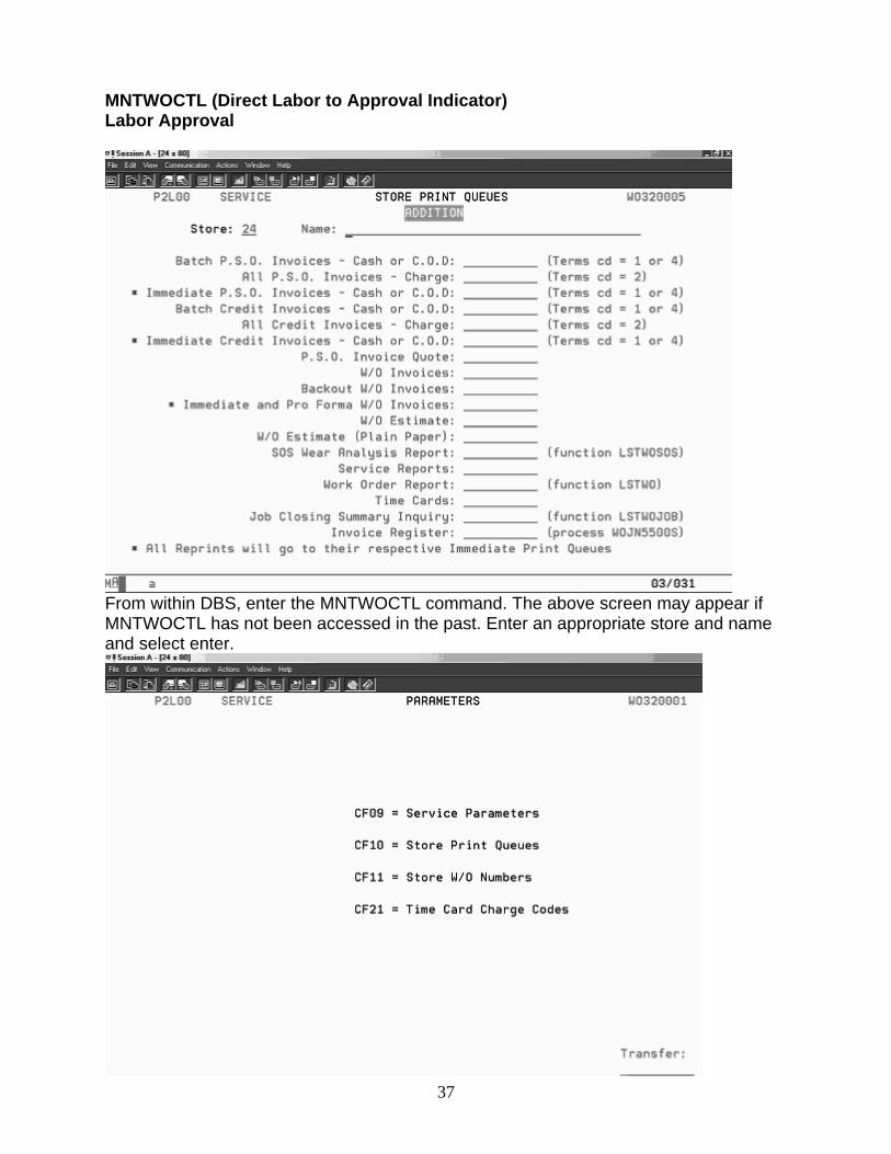
MNTWOCTL (Direct Labor to Approval Indicator) Labor Approval
From within DBS, enter the MNTWOCTL command. The above screen may appear if MNTWOCTL has not been accessed in the past. Enter an appropriate store and name and select enter.
37
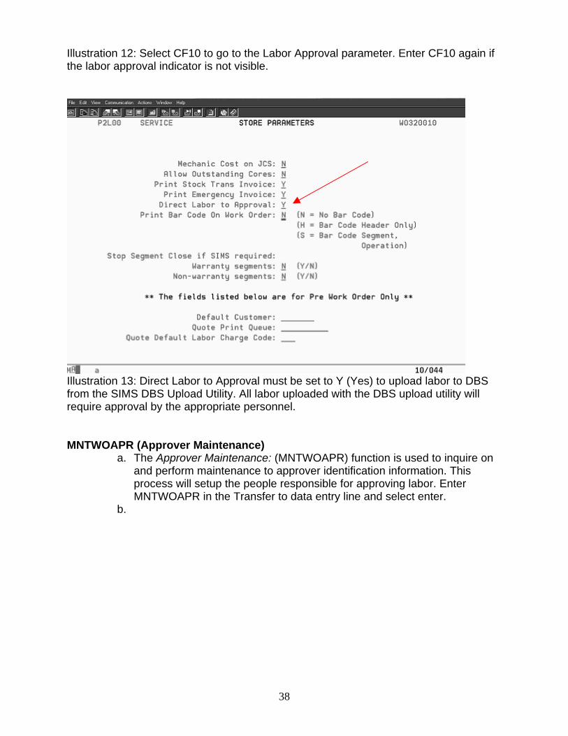
Illustration 12: Select CF10 to go to the Labor Approval parameter. Enter CF10 again if the labor approval indicator is not visible.
Illustration 13: Direct Labor to Approval must be set to Y (Yes) to upload labor to DBS from the SIMS DBS Upload Utility. All labor uploaded with the DBS upload utility will require approval by the appropriate personnel. MNTWOAPR (Approver Maintenance)
a. The Approver Maintenance: (MNTWOAPR) function is used to inquire on and perform maintenance to approver identification information. This process will setup the people responsible for approving labor. Enter MNTWOAPR in the Transfer to data entry line and select enter.
b.
38
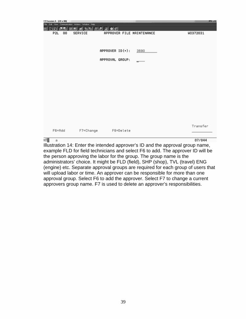
Illustration 14: Enter the intended approver’s ID and the approval group name, example FLD for field technicians and select F6 to add. The approver ID will be the person approving the labor for the group. The group name is the administrators’ choice. It might be FLD (field), SHP (shop), TVL (travel) ENG (engine) etc. Separate approval groups are required for each group of users that will upload labor or time. An approver can be responsible for more than one approval group. Select F6 to add the approver. Select F7 to change a current approvers group name. F7 is used to delete an approver’s responsibilities.
39
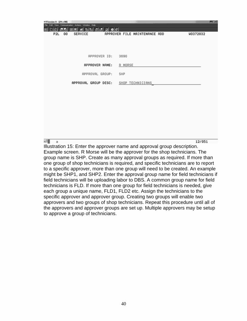
Illustration 15: Enter the approver name and approval group description. Example screen. R Morse will be the approver for the shop technicians. The group name is SHP. Create as many approval groups as required. If more than one group of shop technicians is required, and specific technicians are to report to a specific approver, more than one group will need to be created. An example might be SHP1, and SHP2. Enter the approval group name for field technicians if field technicians will be uploading labor to DBS. A common group name for field technicians is FLD. If more than one group for field technicians is needed, give each group a unique name, FLD1, FLD2 etc. Assign the technicians to the specific approver and approver group. Creating two groups will enable two approvers and two groups of shop technicians. Repeat this procedure until all of the approvers and approver groups are set up. Multiple approvers may be setup to approve a group of technicians.
40
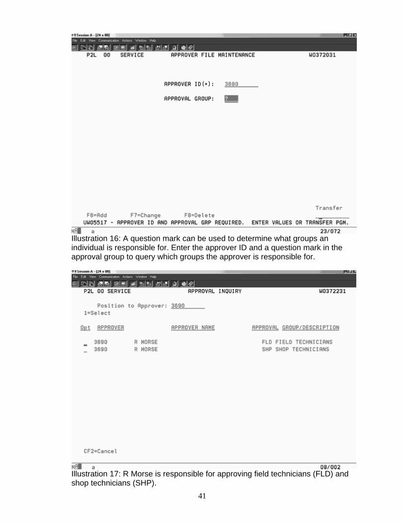
Illustration 16: A question mark can be used to determine what groups an individual is responsible for. Enter the approver ID and a question mark in the approval group to query which groups the approver is responsible for.
Illustration 17: R Morse is responsible for approving field technicians (FLD) and shop technicians (SHP).
41
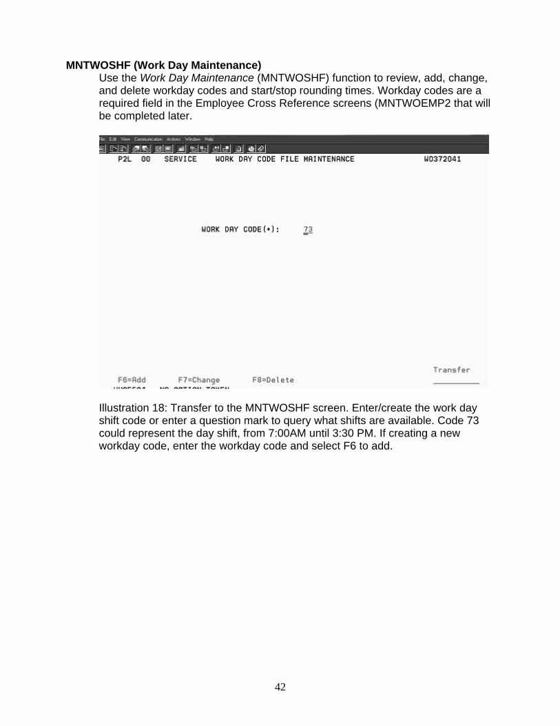
MNTWOSHF (Work Day Maintenance)
Use the Work Day Maintenance (MNTWOSHF) function to review, add, change, and delete workday codes and start/stop rounding times. Workday codes are a required field in the Employee Cross Reference screens (MNTWOEMP2 that will be completed later.
Illustration 18: Transfer to the MNTWOSHF screen. Enter/create the work day shift code or enter a question mark to query what shifts are available. Code 73 could represent the day shift, from 7:00AM until 3:30 PM. If creating a new workday code, enter the workday code and select F6 to add.
42
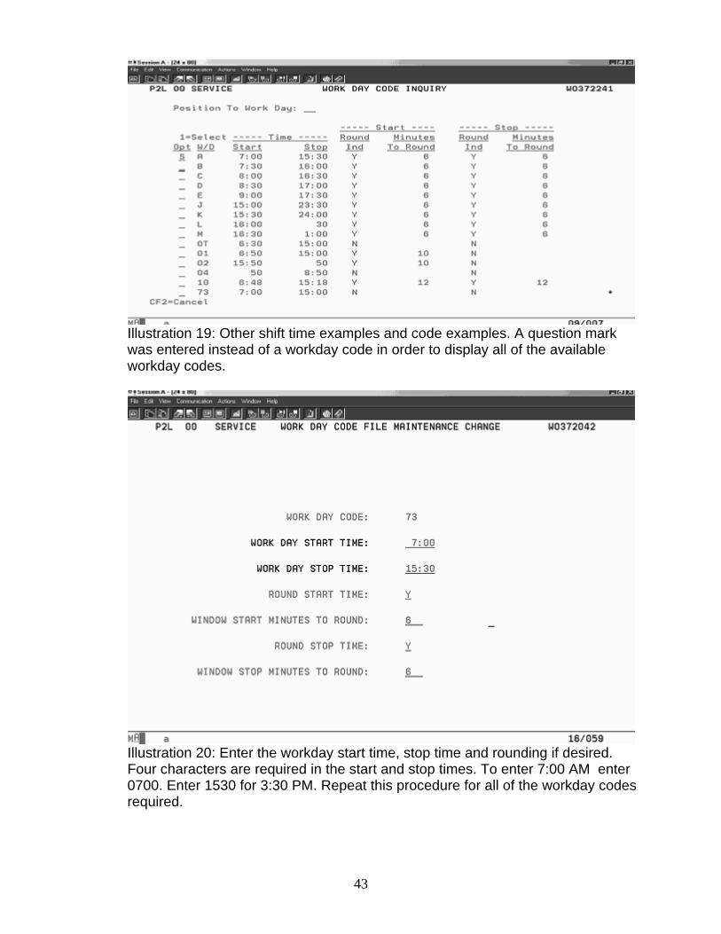
Illustration 19: Other shift time examples and code examples. A question mark was entered instead of a workday code in order to display all of the available workday codes.
Illustration 20: Enter the workday start time, stop time and rounding if desired. Four characters are required in the start and stop times. To enter 7:00 AM enter 0700. Enter 1530 for 3:30 PM. Repeat this procedure for all of the workday codes required.
43
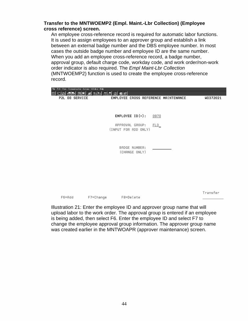
Transfer to the MNTWOEMP2 (Empl. Maint.-Lbr Collection) (Employee cross reference) screen.
An employee cross-reference record is required for automatic labor functions. It is used to assign employees to an approver group and establish a link between an external badge number and the DBS employee number. In most cases the outside badge number and employee ID are the same number. When you add an employee cross-reference record, a badge number, approval group, default charge code, workday code, and work order/non-work order indicator is also required. The Empl Maint-Lbr Collection (MNTWOEMP2) function is used to create the employee cross-reference record.
Illustration 21: Enter the employee ID and approver group name that will upload labor to the work order. The approval group is entered if an employee is being added, then select F6. Enter the employee ID and select F7 to change the employee approval group information. The approver group name was created earlier in the MNTWOAPR (approver maintenance) screen.
44
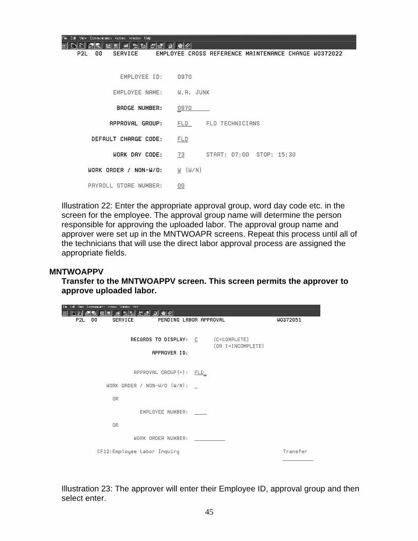
Illustration 22: Enter the appropriate approval group, word day code etc. in the screen for the employee. The approval group name will determine the person responsible for approving the uploaded labor. The approval group name and approver were set up in the MNTWOAPR screens. Repeat this process until all of the technicians that will use the direct labor approval process are assigned the appropriate fields.
MNTWOAPPV Transfer to the MNTWOAPPV screen. This screen permits the approver to approve uploaded labor.
Illustration 23: The approver will enter their Employee ID, approval group and then select enter.
45
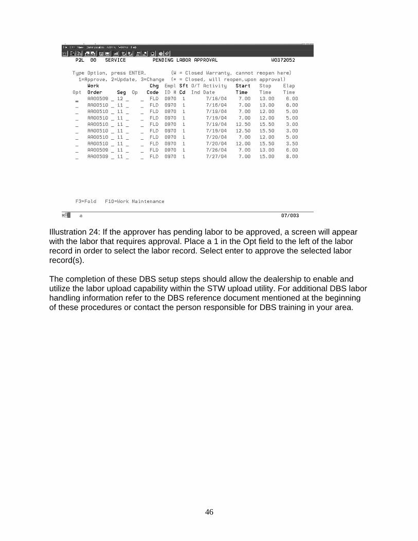
Illustration 24: If the approver has pending labor to be approved, a screen will appear with the labor that requires approval. Place a 1 in the Opt field to the left of the labor record in order to select the labor record. Select enter to approve the selected labor record(s). The completion of these DBS setup steps should allow the dealership to enable and utilize the labor upload capability within the STW upload utility. For additional DBS labor handling information refer to the DBS reference document mentioned at the beginning of these procedures or contact the person responsible for DBS training in your area.
46
Labor Approval Setup – DBS DBS must be setup to approve labor before labor is uploaded using the SIMS DBS utility. Approval is required for all labor that is uploaded to DBS using the SIMS DBS upload utility. Consult the IS department and the person responsible for administering DBS to complete the DBS setup. The DBS setup procedure is also explained in the Getting Started Guide in STW. This information can also be found on the Knowledge Network at https://kn.cat.com/cat.cfm?id=5079&cd=1#current . A CWS login is required to access the Knowledge Network. The Direct Labor Approval - Chapter 6.pdf is the DBS reference document used to create this DBS Setup information. Upload - Multi-segment Starting with STW 2004B, a service report created in STW can contain more than one segment. To prevent uploading duplicate Repair Comments to DBS, upload the service report after all segments have been completed. This is an “End of Job” upload. A separate service report should be created for a segment that needs to be uploaded before other segments in the same work order are completed. Upload Travel Time Using the Service Report and the Upload Utility The travel start time and travel stop time may be uploaded to DBS during the labor upload process. A travel code needs to exist within DBS the same as the Field Technician labor code or FLD needs to exist. TVL is the travel code example used for this explanation.. Travel time is approved from within the employees default labor code screen, FLD, SHP OFC etc. Travel time may be uploaded daily with labor or as an end of job report process.
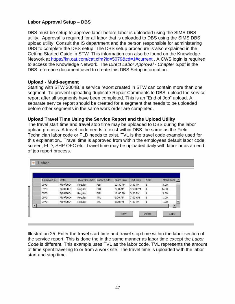
Illustration 25: Enter the travel start time and travel stop time within the labor section of the service report. This is done the in the same manner as labor time except the Labor Code is different. This example uses TVL as the labor code. TVL represents the amount of time spent traveling to or from a work site. The travel time is uploaded with the labor start and stop time.
47
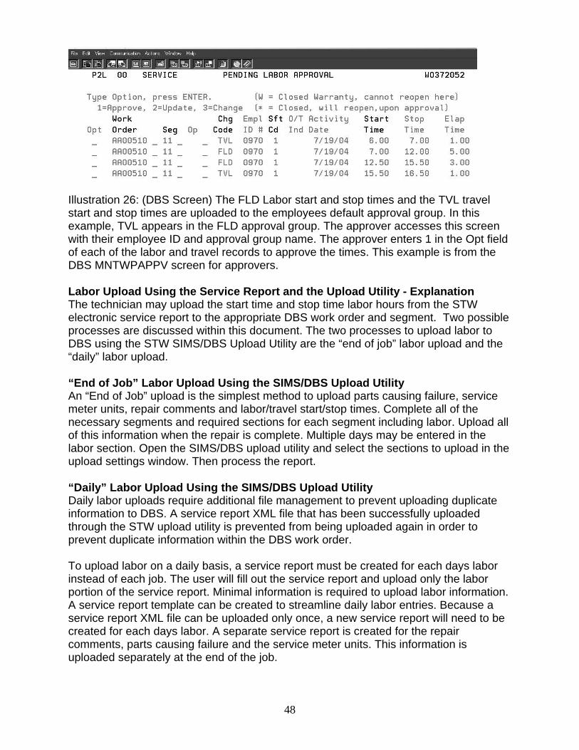
Illustration 26: (DBS Screen) The FLD Labor start and stop times and the TVL travel start and stop times are uploaded to the employees default approval group. In this example, TVL appears in the FLD approval group. The approver accesses this screen with their employee ID and approval group name. The approver enters 1 in the Opt field of each of the labor and travel records to approve the times. This example is from the DBS MNTWPAPPV screen for approvers. Labor Upload Using the Service Report and the Upload Utility - Explanation The technician may upload the start time and stop time labor hours from the STW electronic service report to the appropriate DBS work order and segment. Two possible processes are discussed within this document. The two processes to upload labor to DBS using the STW SIMS/DBS Upload Utility are the “end of job” labor upload and the “daily” labor upload. “End of Job” Labor Upload Using the SIMS/DBS Upload Utility An “End of Job” upload is the simplest method to upload parts causing failure, service meter units, repair comments and labor/travel start/stop times. Complete all of the necessary segments and required sections for each segment including labor. Upload all of this information when the repair is complete. Multiple days may be entered in the labor section. Open the SIMS/DBS upload utility and select the sections to upload in the upload settings window. Then process the report. “Daily” Labor Upload Using the SIMS/DBS Upload Utility Daily labor uploads require additional file management to prevent uploading duplicate information to DBS. A service report XML file that has been successfully uploaded through the STW upload utility is prevented from being uploaded again in order to prevent duplicate information within the DBS work order. To upload labor on a daily basis, a service report must be created for each days labor instead of each job. The user will fill out the service report and upload only the labor portion of the service report. Minimal information is required to upload labor information. A service report template can be created to streamline daily labor entries. Because a service report XML file can be uploaded only once, a new service report will need to be created for each days labor. A separate service report is created for the repair comments, parts causing failure and the service meter units. This information is uploaded separately at the end of the job.
48
Labor Upload –End of Job Setup
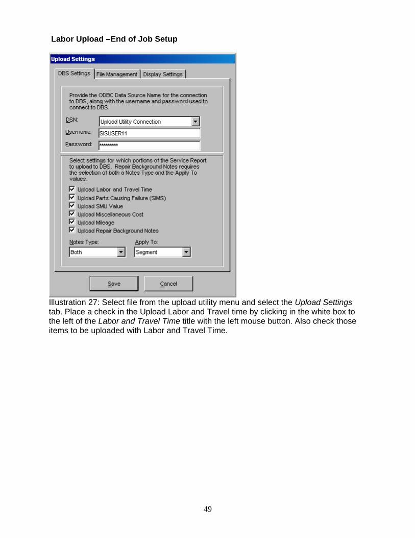
Illustration 27: Select file from the upload utility menu and select the Upload Settings tab. Place a check in the Upload Labor and Travel time by clicking in the white box to the left of the Labor and Travel Time title with the left mouse button. Also check those items to be uploaded with Labor and Travel Time.
49
Labor Upload End of Job Process
Illustration 28: Enter the labor in the service report section that is performed on the work order and segment. Multiple days may be entered in the labor section if the job and segment required more than one day to complete. The upload utility will upload multiple days and multiple segments to DBS. Select New for a new line or select a line and select Copy to duplicate a line. Duplicating a line may be more efficient during the data entry process. Change the appropriate information within the new line. Enter all of the data that is required in the other sections of the service report if this information has not been entered. Save the service report before closing the service report and beginning the upload process.
50
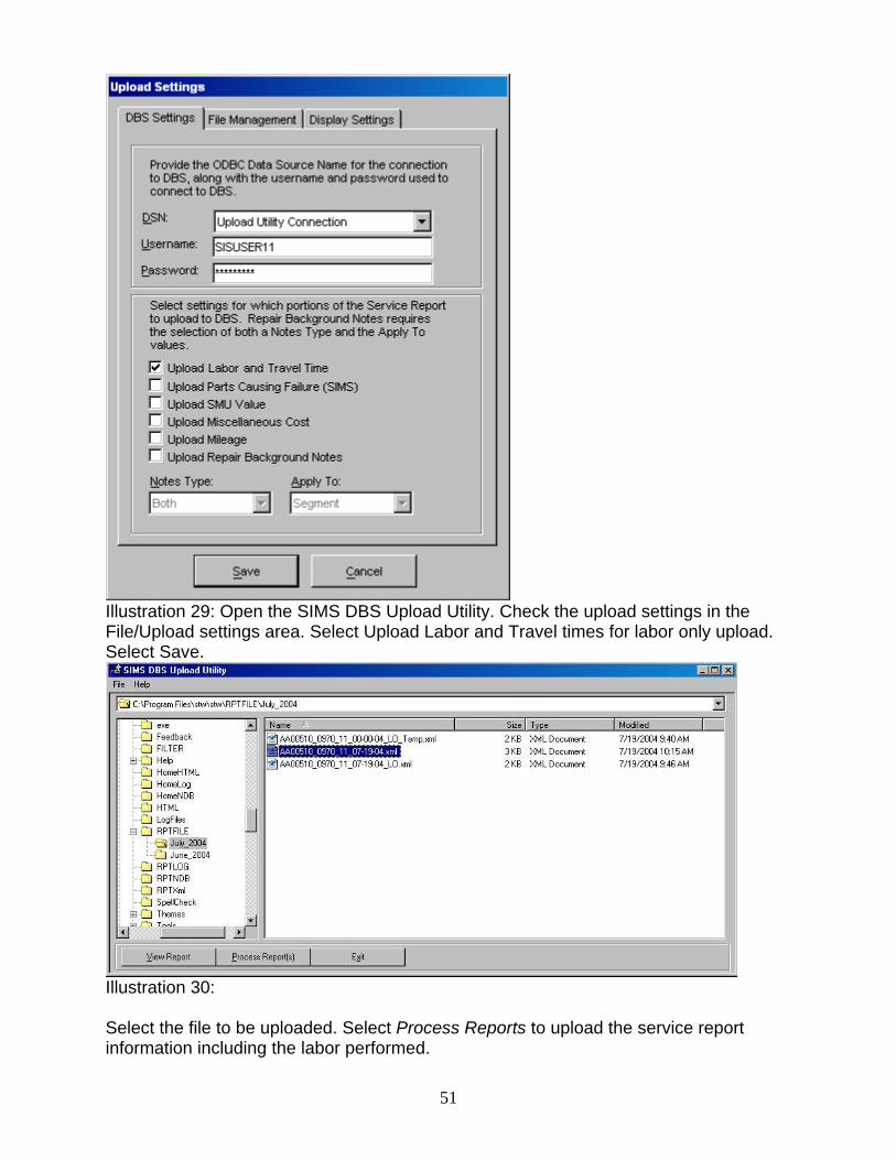
Illustration 29: Open the SIMS DBS Upload Utility. Check the upload settings in the File/Upload settings area. Select Upload Labor and Travel times for labor only upload. Select Save.
Illustration 30: Select the file to be uploaded. Select Process Reports to upload the service report information including the labor performed.
51
Labor Upload - Daily Setup
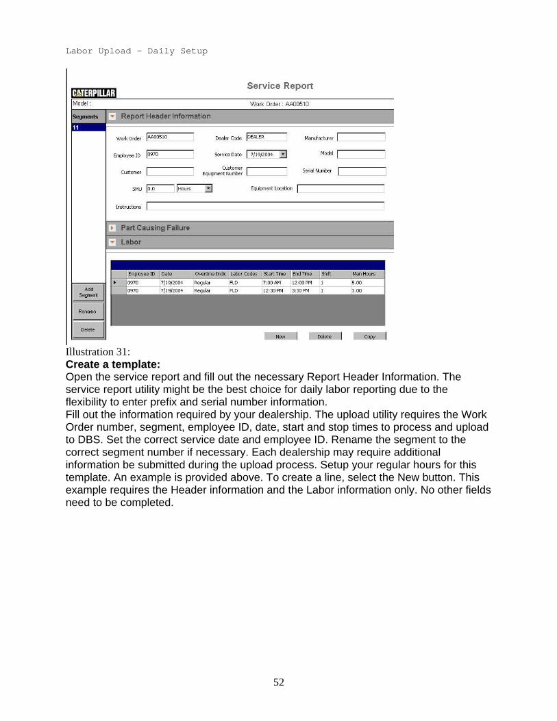
Illustration 31: Create a template: Open the service report and fill out the necessary Report Header Information. The service report utility might be the best choice for daily labor reporting due to the flexibility to enter prefix and serial number information. Fill out the information required by your dealership. The upload utility requires the Work Order number, segment, employee ID, date, start and stop times to process and upload to DBS. Set the correct service date and employee ID. Rename the segment to the correct segment number if necessary. Each dealership may require additional information be submitted during the upload process. Setup your regular hours for this template. An example is provided above. To create a line, select the New button. This example requires the Header information and the Labor information only. No other fields need to be completed.
52
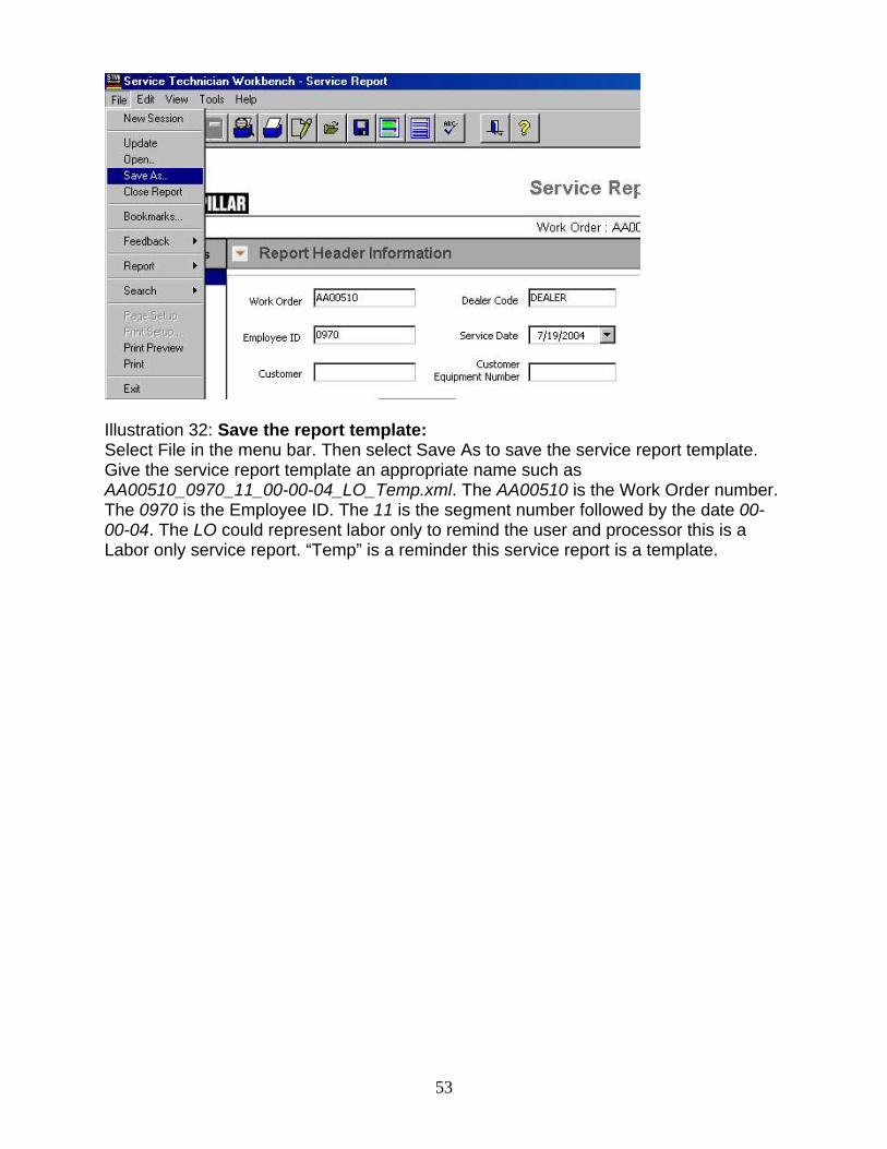
Illustration 32: Save the report template: Select File in the menu bar. Then select Save As to save the service report template. Give the service report template an appropriate name such as AA00510_0970_11_00-00-04_LO_Temp.xml. The AA00510 is the Work Order number. The 0970 is the Employee ID. The 11 is the segment number followed by the date 00-00-04. The LO could represent labor only to remind the user and processor this is a Labor only service report. “Temp” is a reminder this service report is a template.
53
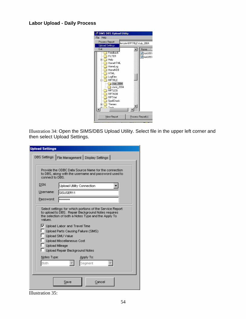
Labor Upload - Daily Process
Illustration 34: Open the SIMS/DBS Upload Utility. Select file in the upper left corner and then select Upload Settings.
Illustration 35:
54
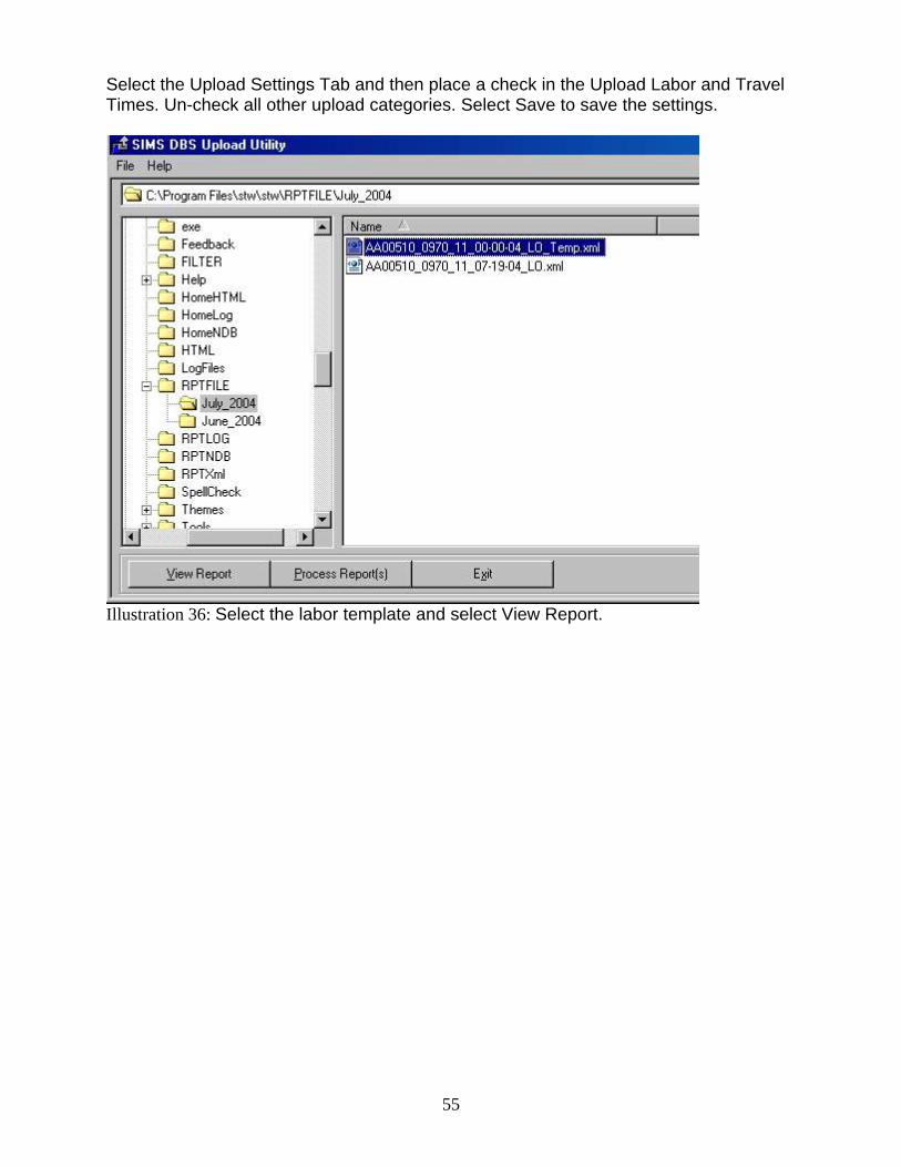
Select the Upload Settings Tab and then place a check in the Upload Labor and Travel Times. Un-check all other upload categories. Select Save to save the settings.
Illustration 36: Select the labor template and select View Report.
55
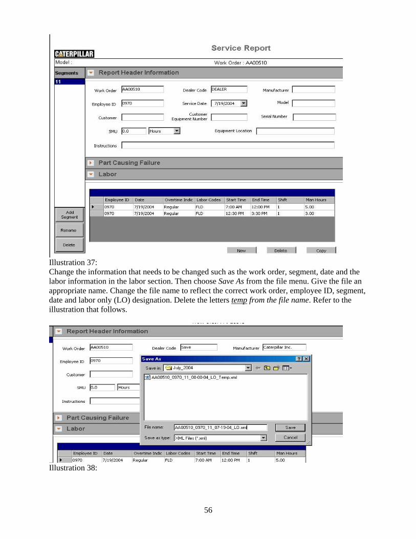
Illustration 37: Change the information that needs to be changed such as the work order, segment, date and the labor information in the labor section. Then choose Save As from the file menu. Give the file an appropriate name. Change the file name to reflect the correct work order, employee ID, segment, date and labor only (LO) designation. Delete the letters temp from the file name. Refer to the illustration that follows.
Illustration 38:
56
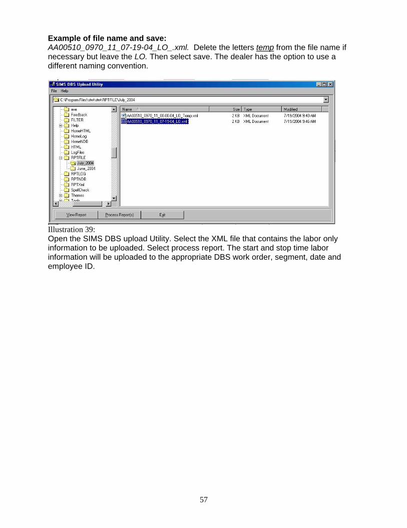
Example of file name and save: AA00510_0970_11_07-19-04_LO_.xml. Delete the letters temp from the file name if necessary but leave the LO. Then select save. The dealer has the option to use a different naming convention.
Illustration 39: Open the SIMS DBS upload Utility. Select the XML file that contains the labor only information to be uploaded. Select process report. The start and stop time labor information will be uploaded to the appropriate DBS work order, segment, date and employee ID.
57
58
Miscellaneous Costs and Mileage The 2006A STW Service Report split the Miscellaneous Costs and Mileage sections. The mileage sections requires fewer fields. Splitting the sections will make it simpler to enter information in the mileage section. Enter the miscellaneous mileage costs in the mileage section and enter the miscellaneous costs in the miscellaneous costs section. If the mileage or miscellaneous costs will be uploaded using the DBS upload utility, the description fields and comments field do not need to be completed. A re-price function is completed in DBS and the description and cost fields are filled in and totaled within DBS. Refer to the What’s New for 2006A document or the Flash Files Search DVD Training Folder – STW folder for more information. Refer to the document, Service Report or Service Report Fields that Upload to DBS. Additional Assistance The following resources are available in Service Technician Workbench and its associated components to provide additional assistance: Help Contents To read the On-line Help, select the Contents choice from the Help option in the menu bar of the STW main screen. Tutorial To view the STW Training Tutorial, see the Service Technician Workbench Tutorial and Support disk NEHS0812. Getting Started Guide To view the STW getting started guide from STW. Click the Help-pull down menu and select Getting Started guide Illustration 80: Service Technician Workbench - STW Home dialog box Help Desk Displays information about obtaining assistance for STW from the DCS Support Center. Refer to page 104 for Hotline Support. Release Notes To read the Release Notes: 1. Click the Help pull-down menu from the STW Home Page. 2. Click on the Release Notes option. ET Support Folder The ET support folder is located on the Service Technician Workbench Tutorial and Support disk NEHS0812. ECM Hotline
59
1-877-598-8920 DCS Support Center: - Voice: (800) 765-0999 (North America ONLY) (309) 675-4000 (Outside North America) - Fax: (309) 674-4080 - E-mail: [email protected] DCS Support Center (Lotus Notes) - Hours: 7:30 am-6:00 pm Monday Through Friday (Central Time) Caterpillar Media and Product Information Logistics: - 1-800-566-7782 (North America ONLY) - 309-266-0942 (Outside North America) - E-mail: [email protected] Component Based Troubleshooting (CBT)
CBT is designed to help the technician troubleshoot symptoms and codes for Caterpillar engines and machines. After identifying a symptom, the technician is presented with a list of components that, if not operating properly, may cause the symptom . By using the information provided for each component, the technician can identify the root cause of the symptom and fix the problem. The technician is also presented with a list of available ECMs and codes for the selected model to troubleshoot codes. In addition, CBT gives the technician links to related information for symptoms and codes in the Service Information System (SIS).
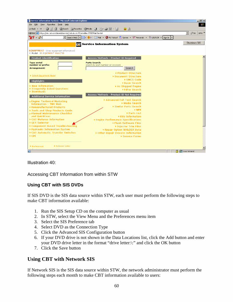
Illustration 40:
Accessing CBT Information from within STW Using CBT with SIS DVDs If SIS DVD is the SIS data source within STW, each user must perform the following steps to make CBT information available:
1. Run the SIS Setup CD on the computer as usual 2. In STW, select the View Menu and the Preferences menu item 3. Select the SIS Preference tab 4. Select DVD as the Connection Type 5. Click the Advanced SIS Configuration button 6. If your DVD drive is not shown in the Data Locations list, click the Add button and enter
your DVD drive letter in the format “drive letter:\:” and click the OK button 7. Click the Save button
Using CBT with Network SIS If Network SIS is the SIS data source within STW, the network administrator must perform the following steps each month to make CBT information available to users:
60
61
1. Run the SIS Setup CD on the network server as usual 2. Go the drive where the SIS data was installed and the open the “appfiles\CBT” directory 3. Double-click on each of the two self-extracting zip files in the directory, cbtdata.exe and
datasets.exe, to extract the CBT data to the correct directories. Please extract in the order listed.
Each user must perform the following steps to make CBT information available:
1. In STW, select the View Menu and the Preferences menu item 2. Select the SIS Preference tab 3. Select Network as the Connection Type 4. In the Data Location box, select or enter the mapped drive letter for the server drive that
contains the “appfiles\CBT” directory described above and click the OK button Using CBT with SIS Web If Web is the SIS data source within STW, each user must perform the following steps to make CBT information available:
1. In STW, select the View Menu and the Preferences menu item 2. Select the SIS Preference tab 3. Select Web as the Connection Type 4. The Component Based Troubleshooting box should contain the default URL
https://cbt.cat.com. Click the OK button.
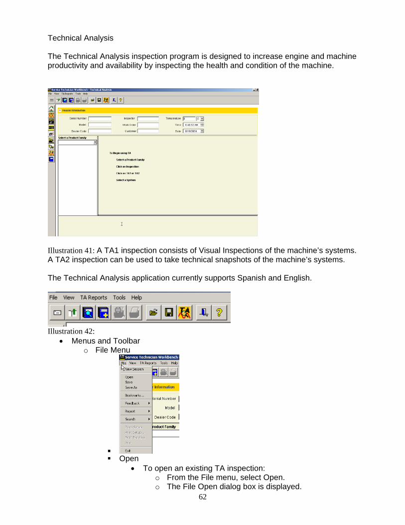
Technical Analysis The Technical Analysis inspection program is designed to increase engine and machine productivity and availability by inspecting the health and condition of the machine.
Illustration 41: A TA1 inspection consists of Visual Inspections of the machine’s systems. A TA2 inspection can be used to take technical snapshots of the machine’s systems. The Technical Analysis application currently supports Spanish and English.
Illustration 42:
• Menus and Toolbar o File Menu
Open
• To open an existing TA inspection: o From the File menu, select Open.
62o The File Open dialog box is displayed.
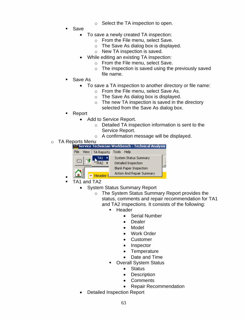
o Select the TA inspection to open. Save
• To save a newly created TA inspection: o From the File menu, select Save. o The Save As dialog box is displayed. o New TA inspection is saved.
• While editing an existing TA inspection: o From the File menu, select Save. o The inspection is saved using the previously saved
file name. Save As
• To save a TA inspection to another directory or file name: o From the File menu, select Save As. o The Save As dialog box is displayed. o The new TA inspection is saved in the directory
selected from the Save As dialog box. Report
• Add to Service Report. o Detailed TA inspection information is sent to the
Service Report. o A confirmation message will be displayed.
o TA Reports Menu
TA1 and TA2
• System Status Summary Report o The System Status Summary Report provides the
status, comments and repair recommendation for TA1 and TA2 inspections. It consists of the following: Header
• Serial Number • Dealer • Model • Work Order • Customer • Inspector • Temperature • Date and Time
Overall System Status • Status • Description • Comments • Repair Recommendation
• Detailed Inspection Report
63
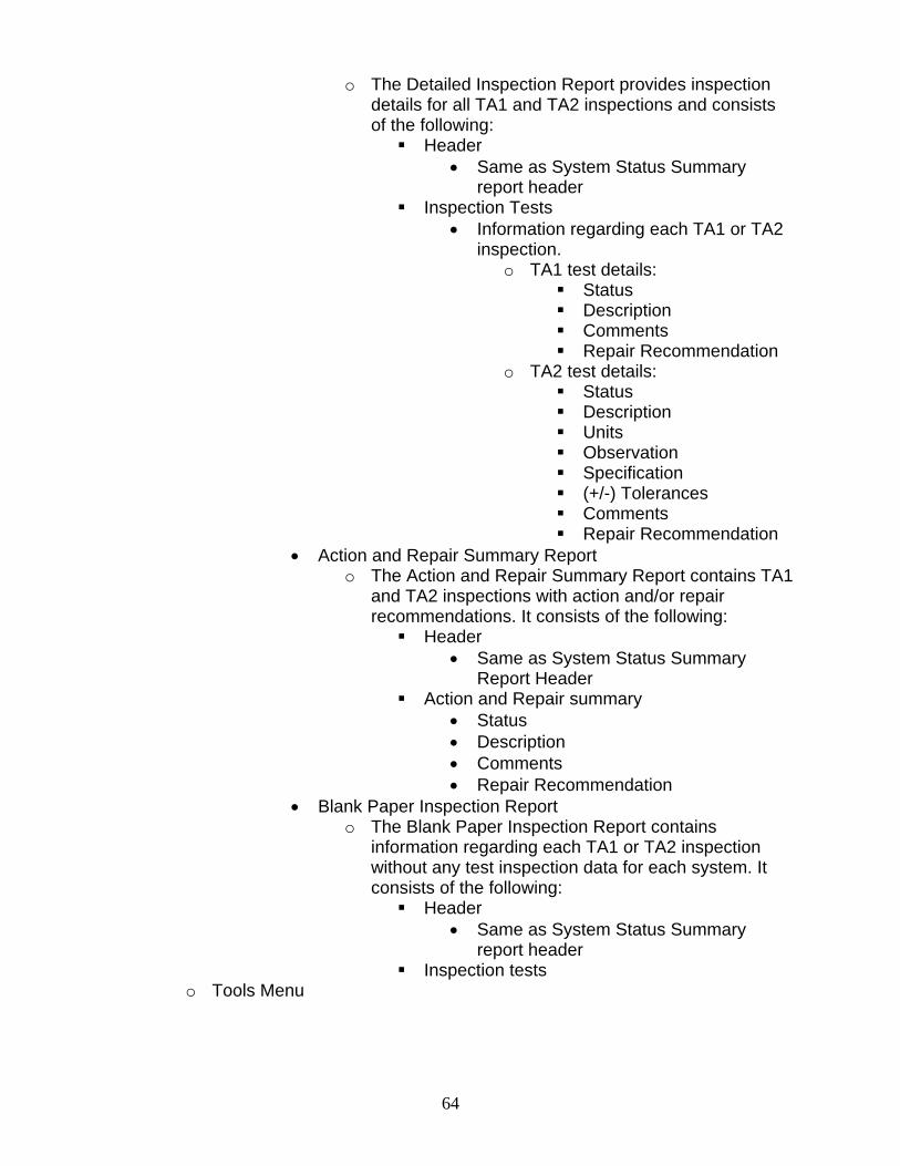
64
o The Detailed Inspection Report provides inspection details for all TA1 and TA2 inspections and consists of the following: Header
• Same as System Status Summary report header
Inspection Tests • Information regarding each TA1 or TA2
inspection. o TA1 test details:
Status Description Comments Repair Recommendation
o TA2 test details: Status Description Units Observation Specification (+/-) Tolerances Comments Repair Recommendation
• Action and Repair Summary Report o The Action and Repair Summary Report contains TA1
and TA2 inspections with action and/or repair recommendations. It consists of the following: Header
• Same as System Status Summary Report Header
Action and Repair summary • Status • Description • Comments • Repair Recommendation
• Blank Paper Inspection Report o The Blank Paper Inspection Report contains
information regarding each TA1 or TA2 inspection without any test inspection data for each system. It consists of the following: Header
• Same as System Status Summary report header
Inspection tests o Tools Menu
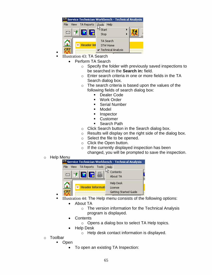
Illustration 43: TA Search
• Perform TA Search o Specify the folder with previously saved inspections to
be searched in the Search in: field. o Enter search criteria in one or more fields in the TA
Search dialog box. o The search criteria is based upon the values of the
following fields of search dialog box: Dealer Code Work Order Serial Number Model Inspector Customer Search Path
o Click Search button in the Search dialog box. o Results will display on the right side of the dialog box. o Select the file to be opened. o Click the Open button. o If the currently displayed inspection has been
changed, you will be prompted to save the inspection. o Help Menu
Illustration 44: The Help menu consists of the following options:
• About TA o The version information for the Technical Analysis
program is displayed. • Contents
o Opens a dialog box to select TA Help topics. • Help Desk
o Help desk contact information is displayed. o Toolbar
Open • To open an existing TA Inspection:
65
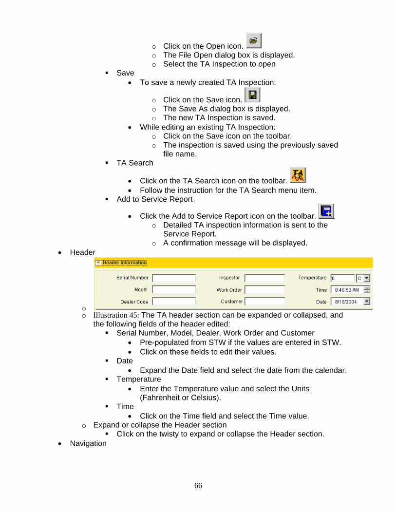
o Click on the Open icon. o The File Open dialog box is displayed. o Select the TA Inspection to open
Save • To save a newly created TA Inspection:
o Click on the Save icon. o The Save As dialog box is displayed. o The new TA Inspection is saved.
• While editing an existing TA Inspection: o Click on the Save icon on the toolbar. o The inspection is saved using the previously saved
file name. TA Search
• Click on the TA Search icon on the toolbar. • Follow the instruction for the TA Search menu item.
Add to Service Report
• Click the Add to Service Report icon on the toolbar. o Detailed TA inspection information is sent to the
Service Report. o A confirmation message will be displayed.
• Header
o o Illustration 45: The TA header section can be expanded or collapsed, and
the following fields of the header edited: Serial Number, Model, Dealer, Work Order and Customer
• Pre-populated from STW if the values are entered in STW. • Click on these fields to edit their values.
Date • Expand the Date field and select the date from the calendar.
Temperature • Enter the Temperature value and select the Units
(Fahrenheit or Celsius). Time
• Click on the Time field and select the Time value. o Expand or collapse the Header section
Click on the twisty to expand or collapse the Header section. • Navigation
66
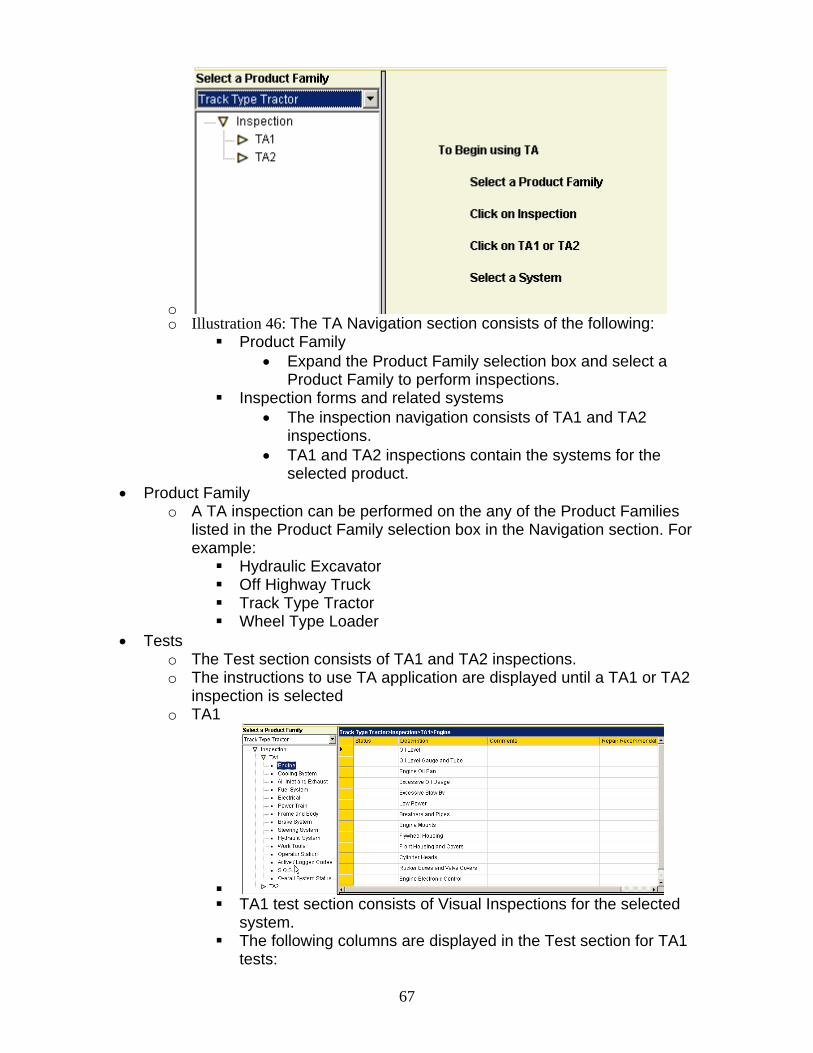
o o Illustration 46: The TA Navigation section consists of the following:
Product Family • Expand the Product Family selection box and select a
Product Family to perform inspections. Inspection forms and related systems
• The inspection navigation consists of TA1 and TA2 inspections.
• TA1 and TA2 inspections contain the systems for the selected product.
• Product Family o A TA inspection can be performed on the any of the Product Families
listed in the Product Family selection box in the Navigation section. For example: Hydraulic Excavator Off Highway Truck Track Type Tractor Wheel Type Loader
• Tests o The Test section consists of TA1 and TA2 inspections. o The instructions to use TA application are displayed until a TA1 or TA2
inspection is selected o TA1
TA1 test section consists of Visual Inspections for the selected
system. The following columns are displayed in the Test section for TA1
tests:
67

• Status
o o Following are items and their background color in the
Status column: o Action - Red. o Monitor - Yellow. o Normal -Green. o Resolved - White.
• Indicate the status of a test by selecting an item from the Status dropdown list. The background color for each Status item is different and changes according to the item selected from the Status dropdown list.
• Description o The Description column is pre-populated with tests for
inspection. o To add more tests, enter the new test in the last row
of the tests. • Comments and Repair Recommendation
o Enter the Comments and Repair Recommendations in the last column.
o TA2
Illustration 47: TA2 test section consists of technical snapshots for
the selected system. The following columns are displayed in the test section for TA2
tests: • Status
o
68
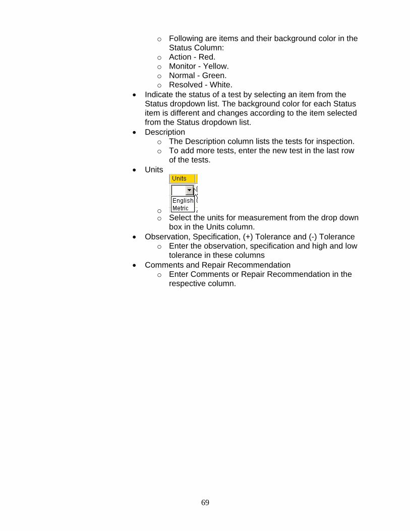
o Following are items and their background color in the Status Column:
o Action - Red. o Monitor - Yellow. o Normal - Green. o Resolved - White.
• Indicate the status of a test by selecting an item from the Status dropdown list. The background color for each Status item is different and changes according to the item selected from the Status dropdown list.
• Description o The Description column lists the tests for inspection. o To add more tests, enter the new test in the last row
of the tests. • Units
o o Select the units for measurement from the drop down
box in the Units column. • Observation, Specification, (+) Tolerance and (-) Tolerance
o Enter the observation, specification and high and low tolerance in these columns
• Comments and Repair Recommendation o Enter Comments or Repair Recommendation in the
respective column.
69
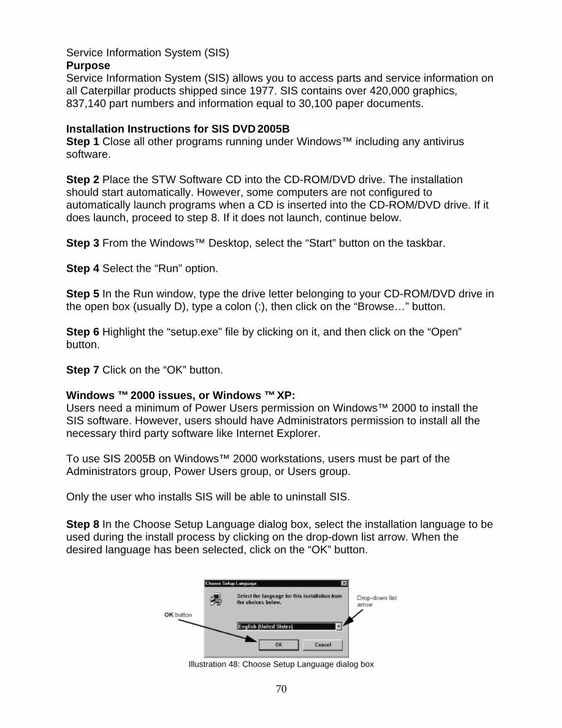
Service Information System (SIS) Purpose Service Information System (SIS) allows you to access parts and service information on all Caterpillar products shipped since 1977. SIS contains over 420,000 graphics, 837,140 part numbers and information equal to 30,100 paper documents. Installation Instructions for SIS DVD 2005B Step 1 Close all other programs running under Windows™ including any antivirus software. Step 2 Place the STW Software CD into the CD-ROM/DVD drive. The installation should start automatically. However, some computers are not configured to automatically launch programs when a CD is inserted into the CD-ROM/DVD drive. If it does launch, proceed to step 8. If it does not launch, continue below. Step 3 From the Windows™ Desktop, select the “Start” button on the taskbar. Step 4 Select the “Run” option. Step 5 In the Run window, type the drive letter belonging to your CD-ROM/DVD drive in the open box (usually D), type a colon (:), then click on the “Browse…” button. Step 6 Highlight the “setup.exe” file by clicking on it, and then click on the “Open” button. Step 7 Click on the “OK” button. Windows ™ 2000 issues, or Windows ™ XP: Users need a minimum of Power Users permission on Windows™ 2000 to install the SIS software. However, users should have Administrators permission to install all the necessary third party software like Internet Explorer. To use SIS 2005B on Windows™ 2000 workstations, users must be part of the Administrators group, Power Users group, or Users group. Only the user who installs SIS will be able to uninstall SIS. Step 8 In the Choose Setup Language dialog box, select the installation language to be used during the install process by clicking on the drop-down list arrow. When the desired language has been selected, click on the “OK” button.
Illustration 48: Choose Setup Language dialog box
70
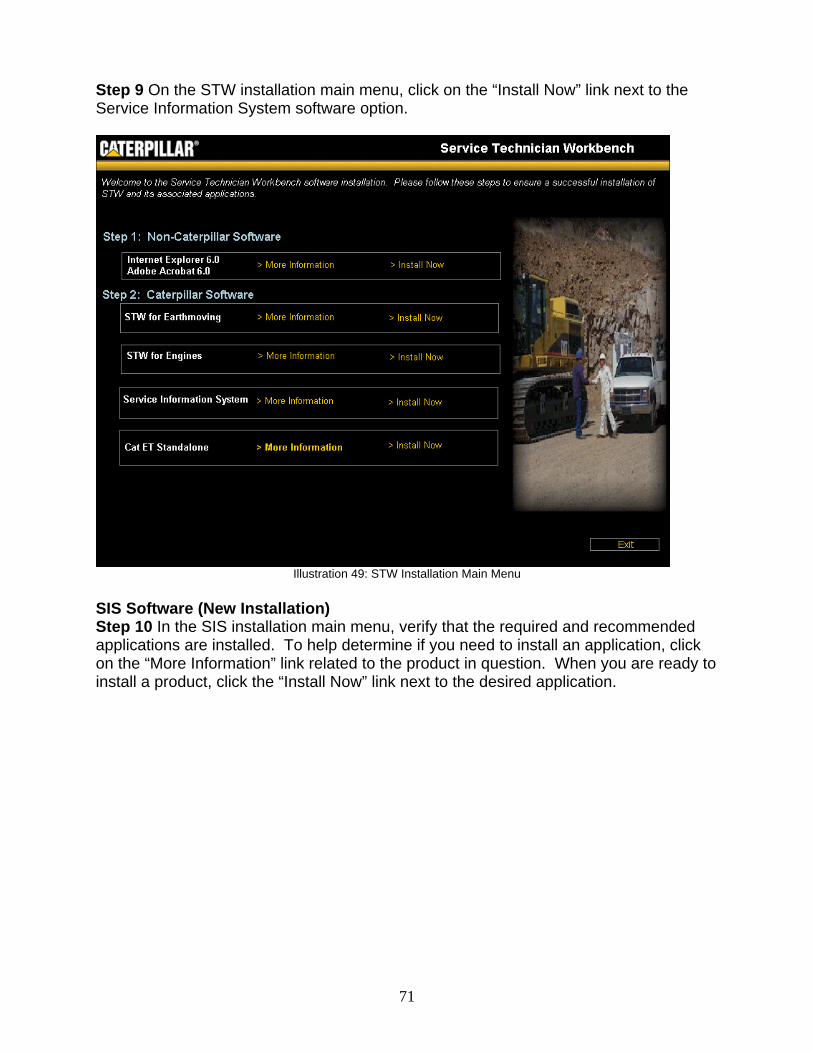
Step 9 On the STW installation main menu, click on the “Install Now” link next to the Service Information System software option.
Illustration 49: STW Installation Main Menu
SIS Software (New Installation) Step 10 In the SIS installation main menu, verify that the required and recommended applications are installed. To help determine if you need to install an application, click on the “More Information” link related to the product in question. When you are ready to install a product, click the “Install Now” link next to the desired application.
71
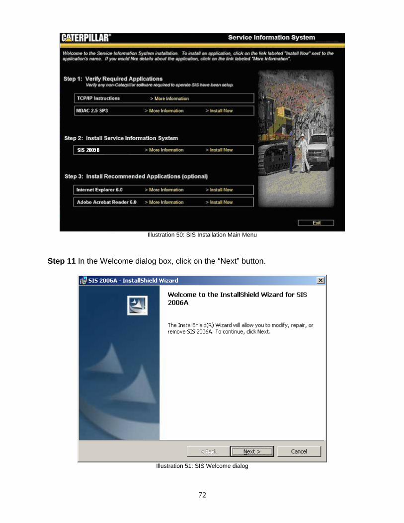
Illustration 50: SIS Installation Main Menu
Step 11 In the Welcome dialog box, click on the “Next” button.
Illustration 51: SIS Welcome dialog
72
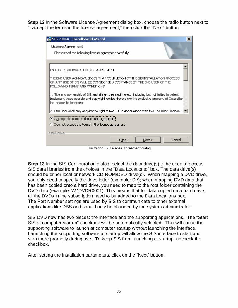
Step 12 In the Software License Agreement dialog box, choose the radio button next to “I accept the terms in the license agreement,” then click the “Next” button.
Illustration 52: License Agreement dialog
Step 13 In the SIS Configuration dialog, select the data drive(s) to be used to access SIS data libraries from the choices in the "Data Locations:" box. The data drive(s) should be either local or network CD-ROM/DVD drive(s). When mapping a DVD drive, you only need to specify the drive letter (example: D:\); when mapping DVD data that has been copied onto a hard drive, you need to map to the root folder containing the DVD data (example: W:\DVDR0001). This means that for data copied on a hard drive, all the DVDs in the subscription need to be added to the Data Locations box. The Port Number settings are used by SIS to communicate to other external applications like DBS and should only be changed by the system administrator. SIS DVD now has two pieces: the interface and the supporting applications. The "Start SIS at computer startup" checkbox will be automatically selected. This will cause the supporting software to launch at computer startup without launching the interface. Launching the supporting software at startup will allow the SIS interface to start and stop more promptly during use. To keep SIS from launching at startup, uncheck the checkbox. After setting the installation parameters, click on the “Next” button.
73
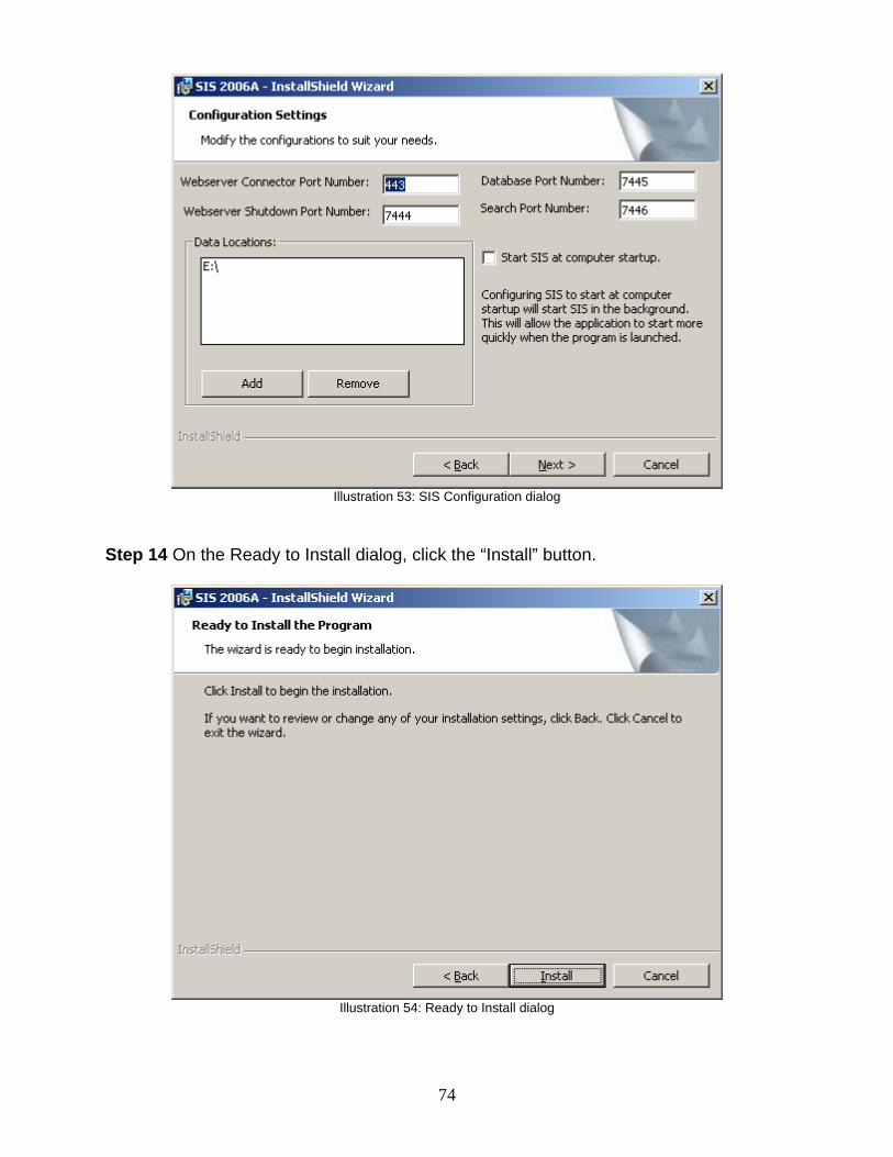
Illustration 53: SIS Configuration dialog
Step 14 On the Ready to Install dialog, click the “Install” button.
Illustration 54: Ready to Install dialog
74
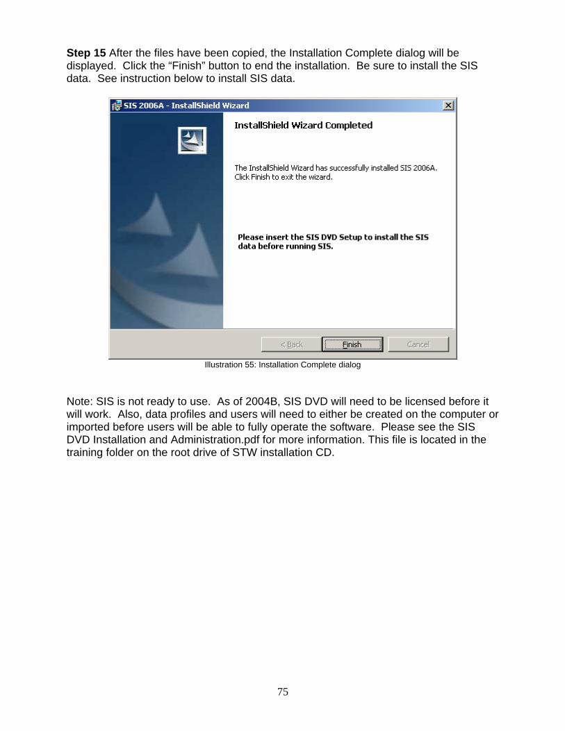
Step 15 After the files have been copied, the Installation Complete dialog will be displayed. Click the “Finish” button to end the installation. Be sure to install the SIS data. See instruction below to install SIS data.
Illustration 55: Installation Complete dialog
Note: SIS is not ready to use. As of 2004B, SIS DVD will need to be licensed before it will work. Also, data profiles and users will need to either be created on the computer or imported before users will be able to fully operate the software. Please see the SIS DVD Installation and Administration.pdf for more information. This file is located in the training folder on the root drive of STW installation CD.
75
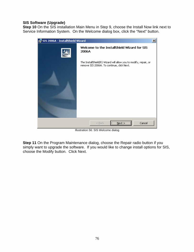
SIS Software (Upgrade) Step 10 On the SIS installation Main Menu in Step 9, choose the Install Now link next to Service Information System. On the Welcome dialog box, click the “Next” button.
Illustration 56: SIS Welcome dialog
Step 11 On the Program Maintenance dialog, choose the Repair radio button if you simply want to upgrade the software. If you would like to change install options for SIS, choose the Modify button. Click Next.
76
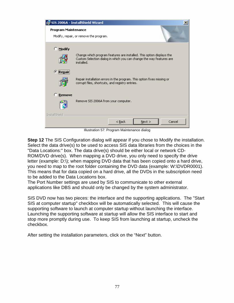
Illustration 57: Program Maintenance dialog
Step 12 The SIS Configuration dialog will appear if you chose to Modify the installation. Select the data drive(s) to be used to access SIS data libraries from the choices in the "Data Locations:" box. The data drive(s) should be either local or network CD-ROM/DVD drive(s). When mapping a DVD drive, you only need to specify the drive letter (example: D:\); when mapping DVD data that has been copied onto a hard drive, you need to map to the root folder containing the DVD data (example: W:\DVDR0001). This means that for data copied on a hard drive, all the DVDs in the subscription need to be added to the Data Locations box. The Port Number settings are used by SIS to communicate to other external applications like DBS and should only be changed by the system administrator. SIS DVD now has two pieces: the interface and the supporting applications. The "Start SIS at computer startup" checkbox will be automatically selected. This will cause the supporting software to launch at computer startup without launching the interface. Launching the supporting software at startup will allow the SIS interface to start and stop more promptly during use. To keep SIS from launching at startup, uncheck the checkbox. After setting the installation parameters, click on the “Next” button.
77
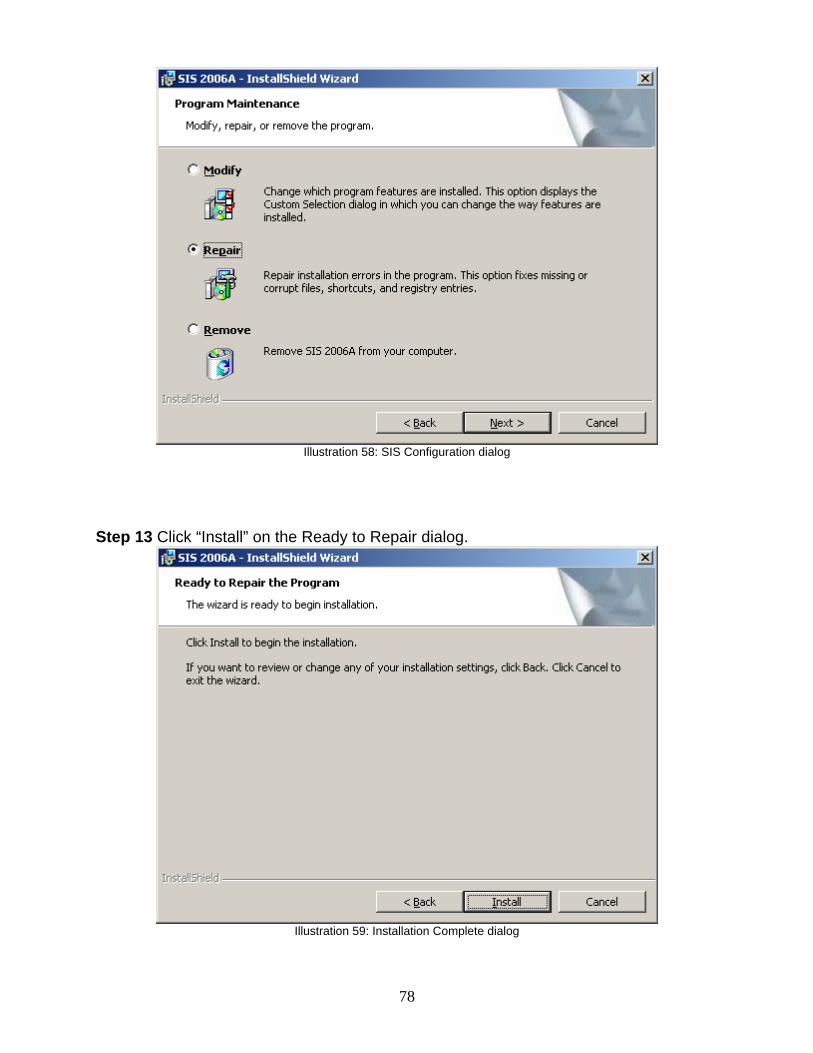
Illustration 58: SIS Configuration dialog
Step 13 Click “Install” on the Ready to Repair dialog.
Illustration 59: Installation Complete dialog
78
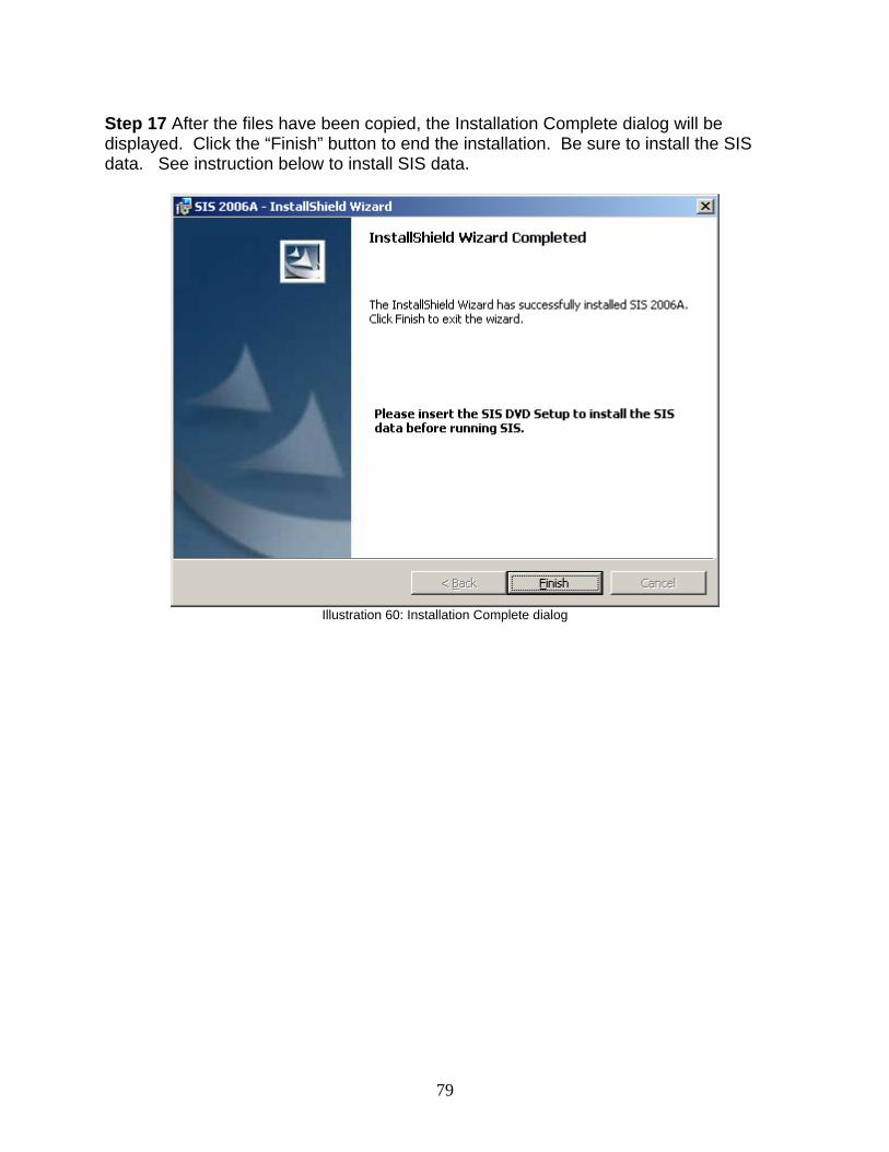
Step 17 After the files have been copied, the Installation Complete dialog will be displayed. Click the “Finish” button to end the installation. Be sure to install the SIS data. See instruction below to install SIS data.
Illustration 60: Installation Complete dialog
79
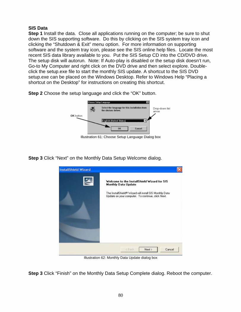
SIS Data Step 1 Install the data. Close all applications running on the computer; be sure to shut down the SIS supporting software. Do this by clicking on the SIS system tray icon and clicking the “Shutdown & Exit” menu option. For more information on supporting software and the system tray icon, please see the SIS online help files. Locate the most recent SIS data library available to you. Put the SIS Setup CD into the CD/DVD drive. The setup disk will autorun. Note: If Auto-play is disabled or the setup disk doesn’t run, Go-to My Computer and right click on the DVD drive and then select explore. Double-click the setup.exe file to start the monthly SIS update. A shortcut to the SIS DVD setup.exe can be placed on the Windows Desktop. Refer to Windows Help “Placing a shortcut on the Desktop” for instructions on creating this shortcut. Step 2 Choose the setup language and click the “OK” button.
Illustration 61: Choose Setup Language Dialog box
Step 3 Click “Next” on the Monthly Data Setup Welcome dialog.
Illustration 62: Monthly Data Update dialog box
Step 3 Click “Finish” on the Monthly Data Setup Complete dialog. Reboot the computer.
80
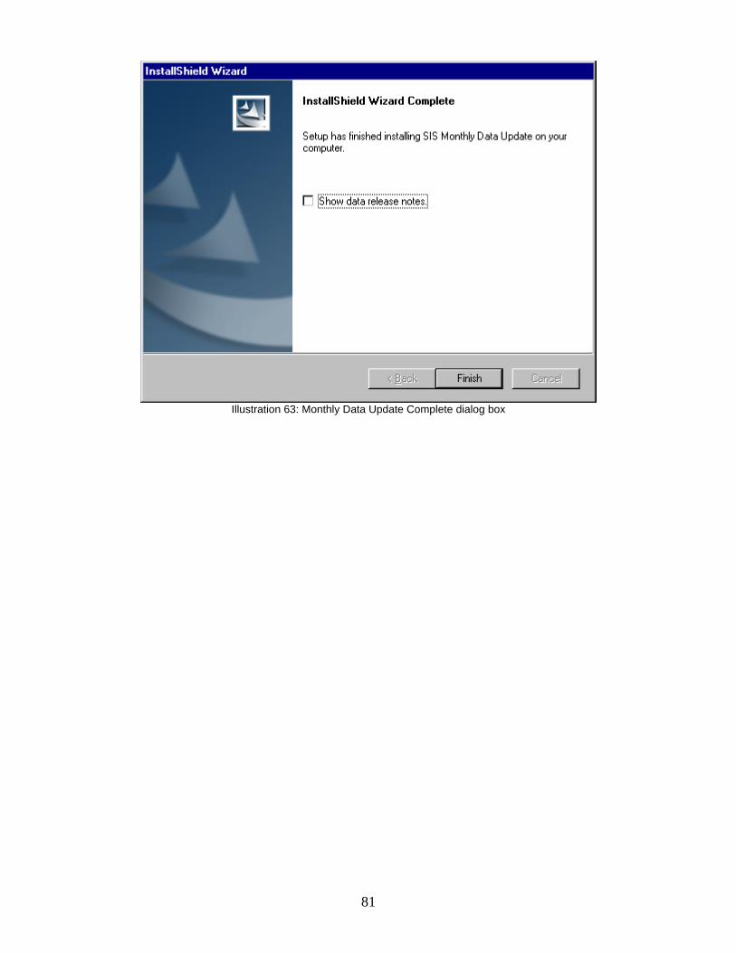
Illustration 63: Monthly Data Update Complete dialog box
81
82
Uninstall Instructions for SIS Windows 2002B or earlier Note: uninstalling a version of SIS Windows after a version of SIS DVD has been installed will corrupt the DvJu plug-in. It is recommended and you uninstall SIS Windows immediately before updating or installing SIS DVD 2006A. Step 1 Close all other programs running under Windows™ including any antivirus software. Step 2 Navigate to the Control Panel, and choose Add/Remove Programs. Step 3 Select “Service Information System” and click the “Change/Remove” button. Step 4 Click “Yes” to confirm the deletion. Step 5 Follow the steps in the uninstall wizard and reboot the computer.
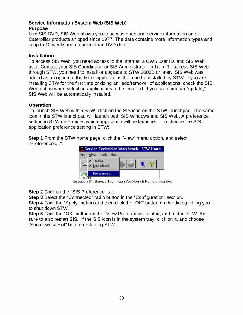
Service Information System Web (SIS Web) Purpose Like SIS DVD, SIS Web allows you to access parts and service information on all Caterpillar products shipped since 1977. The data contains more information types and is up to 12 weeks more current than DVD data. Installation To access SIS Web, you need access to the internet, a CWS user ID, and SIS Web user. Contact your SIS Coordinator or SIS Administrator for help. To access SIS Web through STW, you need to install or upgrade to STW 2003B or later. SIS Web was added as an option to the list of applications that can be installed by STW. If you are installing STW for the first time or doing an "add/remove" of applications, check the SIS Web option when selecting applications to be installed. If you are doing an "update," SIS Web will be automatically installed. Operation To launch SIS Web within STW, click on the SIS icon on the STW launchpad. The same icon in the STW launchpad will launch both SIS Windows and SIS Web. A preference setting in STW determines which application will be launched. To change the SIS application preference setting in STW: Step 1 From the STW home page, click the "View" menu option, and select "Preferences...".
Illustration 64: Service Technician Workbench Home dialog box
Step 2 Click on the "SIS Preference" tab. Step 3 Select the “Connected” radio button in the “Configuration” section. Step 4 Click the "Apply" button and then click the "OK" button on the dialog telling you to shut down STW. Step 5 Click the "OK" button on the "View Preferences" dialog, and restart STW. Be sure to also restart SIS. If the SIS icon is in the system tray, click on it, and choose “Shutdown & Exit” before restarting STW.
83
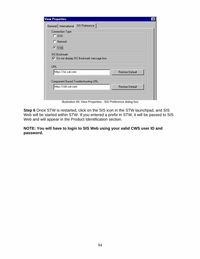
Illustration 65: View Properties - SIS Preference dialog box
Step 6 Once STW is restarted, click on the SIS icon in the STW launchpad, and SIS Web will be started within STW. If you entered a prefix in STW, it will be passed to SIS Web and will appear in the Product Identification section. NOTE: You will have to login to SIS Web using your valid CWS user ID and password.
84
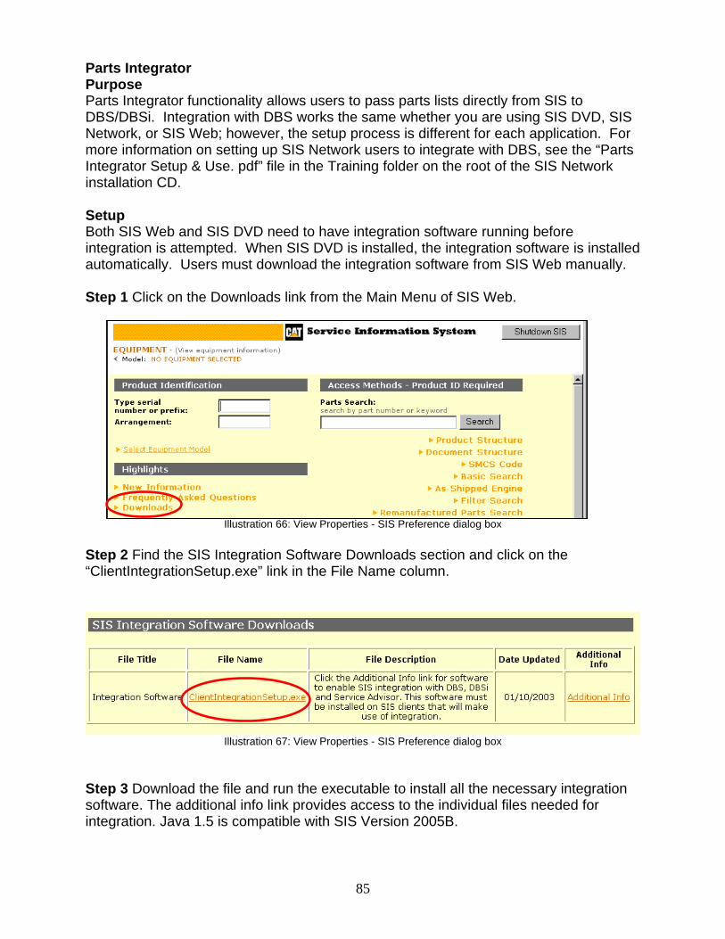
Parts Integrator Purpose Parts Integrator functionality allows users to pass parts lists directly from SIS to DBS/DBSi. Integration with DBS works the same whether you are using SIS DVD, SIS Network, or SIS Web; however, the setup process is different for each application. For more information on setting up SIS Network users to integrate with DBS, see the “Parts Integrator Setup & Use. pdf” file in the Training folder on the root of the SIS Network installation CD. Setup Both SIS Web and SIS DVD need to have integration software running before integration is attempted. When SIS DVD is installed, the integration software is installed automatically. Users must download the integration software from SIS Web manually. Step 1 Click on the Downloads link from the Main Menu of SIS Web.
85
Illustration 66: View Properties - SIS Preference dialog box
Step 2 Find the SIS Integration Software Downloads section and click on the “ClientIntegrationSetup.exe” link in the File Name column.
Illustration 67: View Properties - SIS Preference dialog box
Step 3 Download the file and run the executable to install all the necessary integration software. The additional info link provides access to the individual files needed for integration. Java 1.5 is compatible with SIS Version 2005B.
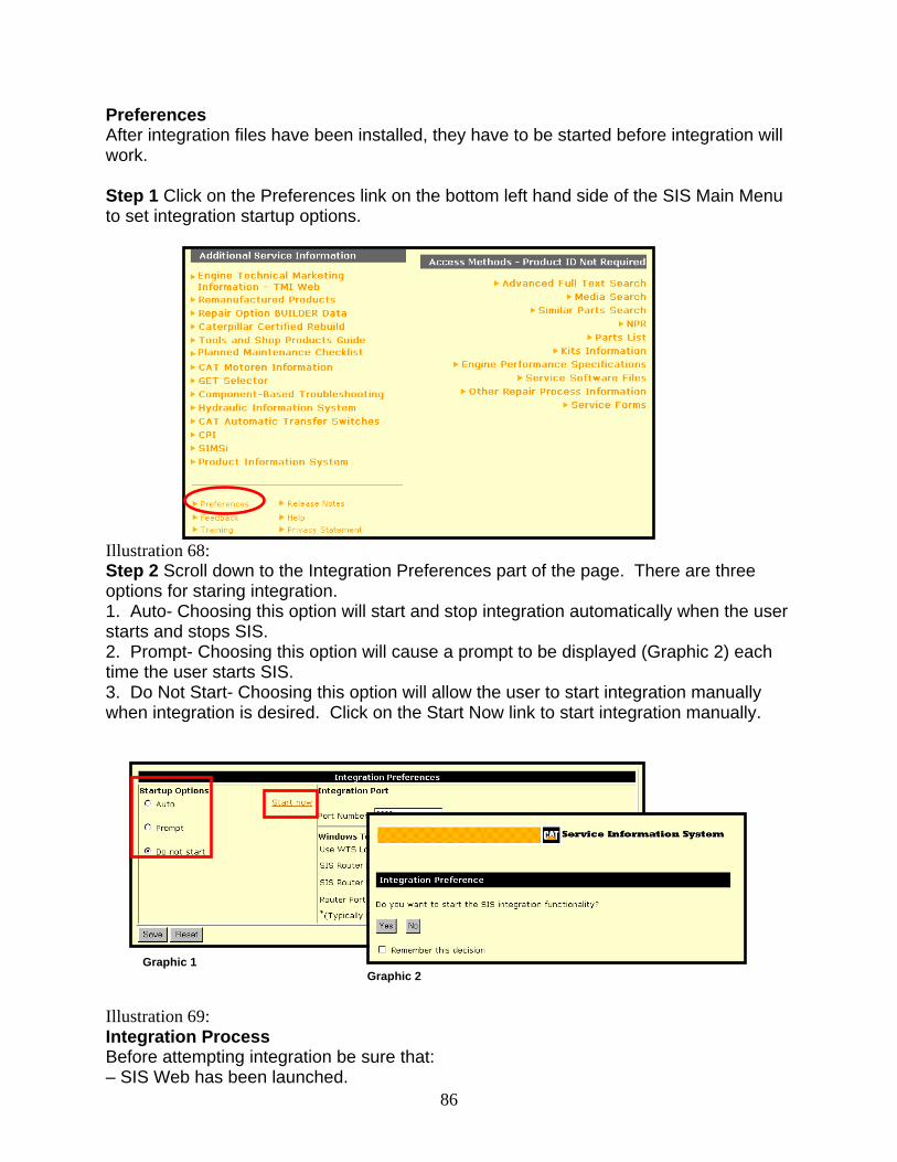
Preferences After integration files have been installed, they have to be started before integration will work. Step 1 Click on the Preferences link on the bottom left hand side of the SIS Main Menu to set integration startup options. Illustration 68: Step 2 Scroll down to the Integration Preferences part of the page. There are three options for staring integration. 1. Auto- Choosing this option will start and stop integration automatically when the user starts and stops SIS. 2. Prompt- Choosing this option will cause a prompt to be displayed (Graphic 2) each time the user starts SIS.
86
3. Do Not Start- Choosing this option will allow the user to start integration manually when integration is desired. Click on the Start Now link to start integration manually.
Graphic 2
Graphic 1 Illustration 69: Integration Process Before attempting integration be sure that: – SIS Web has been launched.
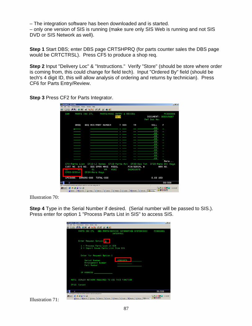
– The integration software has been downloaded and is started. – only one version of SIS is running (make sure only SIS Web is running and not SIS DVD or SIS Network as well). Step 1 Start DBS; enter DBS page CRTSHPRQ (for parts counter sales the DBS page would be CRTCTRSL). Press CF5 to produce a shop req. Step 2 Input "Delivery Loc" & "Instructions." Verify "Store" (should be store where order is coming from, this could change for field tech). Input "Ordered By" field (should be tech's 4 digit ID, this will allow analysis of ordering and returns by technician). Press CF6 for Parts Entry/Review. Step 3 Press CF2 for Parts Integrator. Illustration 70: Step 4 Type in the Serial Number if desired. (Serial number will be passed to SIS.). Press enter for option 1 "Process Parts List in SIS" to access SIS.
Illustration 71:
87
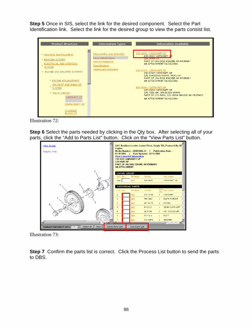
Step 5 Once in SIS, select the link for the desired component. Select the Part Identification link. Select the link for the desired group to view the parts consist list.
88
Illustration 72: Step 6 Select the parts needed by clicking in the Qty box. After selecting all of your parts, click the “Add to Parts List” button. Click on the “View Parts List” button.
Illustration 73: Step 7 Confirm the parts list is correct. Click the Process List button to send the parts to DBS.
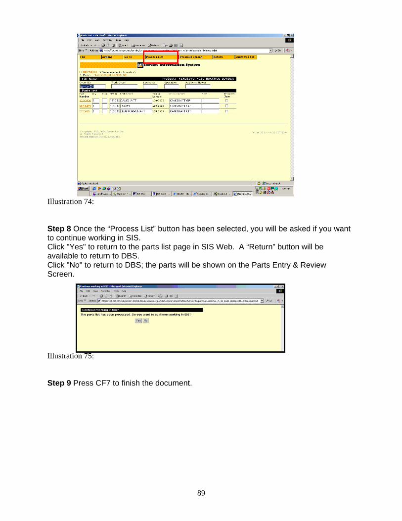
Illustration 74: Step 8 Once the “Process List” button has been selected, you will be asked if you want to continue working in SIS. Click "Yes" to return to the parts list page in SIS Web. A “Return” button will be available to return to DBS. Click "No" to return to DBS; the parts will be shown on the Parts Entry & Review Screen.
89
Illustration 75: Step 9 Press CF7 to finish the document.
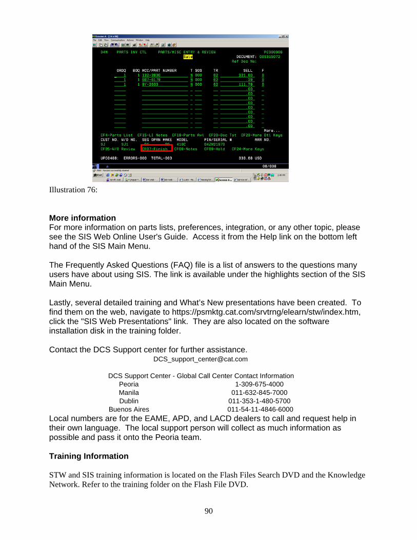
Illustration 76: More information For more information on parts lists, preferences, integration, or any other topic, please see the SIS Web Online User's Guide. Access it from the Help link on the bottom left hand of the SIS Main Menu. The Frequently Asked Questions (FAQ) file is a list of answers to the questions many users have about using SIS. The link is available under the highlights section of the SIS Main Menu. Lastly, several detailed training and What’s New presentations have been created. To find them on the web, navigate to https://psmktg.cat.com/srvtrng/elearn/stw/index.htm, click the "SIS Web Presentations" link. They are also located on the software installation disk in the training folder. Contact the DCS Support center for further assistance. [email protected]
DCS Support Center - Global Call Center Contact Information Peoria 1-309-675-4000Manila 011-632-845-7000Dublin 011-353-1-480-5700
Buenos Aires 011-54-11-4846-6000 Local numbers are for the EAME, APD, and LACD dealers to call and request help in their own language. The local support person will collect as much information as possible and pass it onto the Peoria team. Training Information STW and SIS training information is located on the Flash Files Search DVD and the Knowledge Network. Refer to the training folder on the Flash File DVD.
90

91
Refer to the STW Knowledge Entry list – Training Material subject at https://kn.cat.com/cat.cfm?id=5079&ke=1#currentKE Refer to the SIS Knowledge Entry list – Training Material subject at https://kn.cat.com/cat.cfm?id=5090&ke=1#currentKE Call 309 675-1123 with your training questions or email [email protected]