CATEGORY 1 Unit Pacific Ga Unit Pacific Ga NAME ic ... · CATEGORY 1" „ REGULA INFORMATION...
78
CATEGORY 1" „ REGULA INFORMATION DISTRIBUTIO YSTEM (RIDS) ACCESSION NBR:9803030215 DOC.DATE: 98/02/23 NOTARIZED: YES ~ ~ ACIL:50-275 Diablo Canyon Nuclear Power Plantt, Unit 1, Pacific Ga 50-323 Diablo Canyon Nuclear Power Plant, Unit 2, Pacific Ga AUTH. NAME AUTHOR AFFILIATION WOMACK,L.F. Pacif ic Gas & Electric Co. RECIP.NAME RECIPIENT AFFILIATION Document Control Branch (Document Control Desk) DOCKET 05000275 05000323 SUBJECT: Forwards non-proprietary response to RAI re TRs WCAP-14707 6 C WCAP-14708,Electricite de France repts D.5716/CTT/RB 97.6129 & D.5716/CTT/RS 94.6124 & proprietary W,Science & Technology rept 94-7TE2-DAPER-R1.W/affidavit. Proprietary info withheld. T DISTRIBUTION CODE: APOID COPIES RECEIVED:LTR i ENCL I SIZE: g 4 ltd TITLE: Proprietary Review Distribution - Pre Operating License &, Operating Bg NOTES: RECIPIENT ID CODE/NAME PD4-2 LA BLOOM,S COPIES 'ECIPIENT LTTR ENCL ID CODE/NAME 1 1 PD4-2 PD 1 1 COPIES LTTR ENCL 3 1 INTERNAL: ACRS OGC/HDS3 1 1 1 0 FILE CENTER 0 1 1 TERNAL: NRC PDR ) ~($ 18 -D 0 U M N NOTE TO ALL "RIDS" RECIPIENTS: PLEASE HELP US TO REDUCE WASTE. TO HAVE YOUR NAME OR ORGANIZATION REMOVED FROM DISTRIBUTION LISTS OR REDUCE THE NUMBER OF COPIES RECEIVED BY YOU OR YOUR ORGANIZATION, CONTACT THE DOCUMENT CONTROL DESK (DCD) ON EXTENSION 415-2083 TOTAL NUMBER OF COP1ES REQUIRED: LTTR ~ ENCL
Transcript of CATEGORY 1 Unit Pacific Ga Unit Pacific Ga NAME ic ... · CATEGORY 1" „ REGULA INFORMATION...

CATEGORY 1"
„REGULA INFORMATION DISTRIBUTIO YSTEM (RIDS)
ACCESSION NBR:9803030215 DOC.DATE: 98/02/23 NOTARIZED: YES
~ ~
ACIL:50-275 Diablo Canyon Nuclear Power Plantt, Unit 1, Pacific Ga50-323 Diablo Canyon Nuclear Power Plant, Unit 2, Pacific Ga
AUTH.NAME AUTHOR AFFILIATIONWOMACK,L.F. Pacif ic Gas & Electric Co.
RECIP.NAME RECIPIENT AFFILIATIONDocument Control Branch (Document Control Desk)
DOCKET0500027505000323
SUBJECT: Forwards non-proprietary response to RAI re TRs WCAP-14707 6 CWCAP-14708,Electricite de France repts D.5716/CTT/RB 97.6129& D.5716/CTT/RS 94.6124 & proprietary W,Science & Technologyrept 94-7TE2-DAPER-R1.W/affidavit. Proprietary info withheld.
TDISTRIBUTION CODE: APOID COPIES RECEIVED:LTR i ENCL I SIZE: g 4 ltdTITLE: Proprietary Review Distribution - Pre Operating License &, Operating Bg
NOTES:
RECIPIENTID CODE/NAME
PD4-2 LABLOOM,S
COPIES 'ECIPIENTLTTR ENCL ID CODE/NAME
1 1 PD4-2 PD1 1
COPIESLTTR ENCL
3 1
INTERNAL: ACRSOGC/HDS3
1 11 0
FILE CENTER 0 1 1
TERNAL: NRC PDR ) ~($18
-D
0
U
M
N
NOTE TO ALL "RIDS" RECIPIENTS:PLEASE HELP US TO REDUCE WASTE. TO HAVE YOUR NAME OR ORGANIZATION REMOVED FROM DISTRIBUTION LISTSOR REDUCE THE NUMBER OF COPIES RECEIVED BY YOU OR YOUR ORGANIZATION, CONTACT THE DOCUMENT CONTROLDESK (DCD) ON EXTENSION 415-2083
TOTAL NUMBER OF COP1ES REQUIRED: LTTR ~ ENCL
S'
ct
1
t
r

Pacific Gas and Electric Company 245 Market Street, Room 836-N9BSan Francisco, CA 94105
iiralliugcirldp83s'ail
Code N9BP.O. Box 770000San Francisco, CA 94177415/973-0600 Fax 415/973-6567
Lawrence F. WomackVice PresidentNuclear Technical Services
February 23, 1998
PG&E Letter DCL-98-025
U.S. Nuclear Regulatory CommissionATTN: Document Control DeskWashington, D.C. 20555
Docket No. 50-275, OL-DPR-80Docket No. 50-323, OL-DPR-82Diablo Canyon Units 1 and 2Res onse to NRC Re uest for Additional InformationWCAP-1 4707 and 14708
Dear Commissioners and Staff:
PG&E Letter DCL-96-206, dated October 4, 1996, transmitted to the NRCWestinghouse technical reports WCAP-14707 (proprietary) andWCAP-14708 (nonproprietary), "Model 51 Steam Generator Limited TubeSupport Plate Displacement Analysis for Dented or Packed Tube-to-TubeSupport Plate Crevices."
In a letter to PG&E dated December 2, 1997, the NRC staff requestedadditional information that was required to complete their review of thetechnical reports. Based on discussions with the NRR Project Manager forDiablo Canyon, the due date for response to the NRC request was extendedfrom January 9 to February 23, 1998. PG&E's response to the request foradditional information is enclosed. The enclosure includes two attachments:Attachment 1 contains a supplement to the response to NRC Question 2;Attachment 2 contains a copy of References 2, 3, and 4 of WCAP-14707, asrequested in NRC Question 1. It should be noted that References 2 and 3were previously considered to be confidential. PG&E has receivedconfirmation that these two documents may now be submitted withoutrestriction and, therefore, no exemption in accordance with 10 CFR 2.790 is
requested.
98030302t5 880223PDR ADOCK OS00027SP P08
GSC~GG/tPj Qt
I
,.gIIIIIIIIIllllllllllIIIIIIllllllLII

a-
~'\

U.S. Nuclear Regulatgory CommissionFebruary 23, 1998Page 2
Reference 4, "Westinghouse Science and Technology Report 94-7TE2-DAPER-R1,Characterization of Crevice Deposits in the Dampierre Unit 1 Steam Generator TubeSupport Plate Assembly," contains proprietary information. Accordingly, Attachment 2includes a Westinghouse Application for Withholding Proprietary Information fromPublic Disclosure, a Proprietary Information Notice, a Copyright Notice, and anaccompanying AffidavitCAW-98-1211 signed by Westinghouse, the owner of theinformation. The affidavit sets forth the basis upon which the information may bewithheld from public disclosure by the Commission, and it addresses with specificity theconsiderations listed in paragraph (b)(4) of 10 FR 2.790. PGRE requests that theWestinghouse proprietary information be withheld from public disclosure in accordancewith 10 CFR 2.790.
Correspondence with respect to the proprietary aspects of the Westinghouse reportlisted above or the supporting information provided in Attachment 2 should referenceWestinghouse Letter CAS-98-1211 and be addressed to Henry A. Sepp, Manager,Regulatory and Licensing Engineering, Westinghouse Electric Corporation,P.O. Box 355, Pittsburgh, Pennsylvania 15230-0355.
Sincerely,
Lawrence F. Womack
c: Steven D. BloomEllis W. Merschoff (w/o Attach. 2)Kenneth E. Perkins (w/o Attach. 2)David L. Proulx (w/o Attach. 2)Diablo Distribution (w/o Figures and Attach. 2)
Enclosure
RLJ/2057

~ ~
PG&E Letter DCL-98-025
ENCLOSURE
RESPONSE TO NRC REQUEST FOR ADDITIONALINFORMATIONWCAP-14707 AND WCAP-14708
Attachment 1 —Supplement to the Response to NRC Question 2
Attachment 2 —Copy of References 2, 3, and 4 of WCAP-14707
9803030215'


EnclosurePG&E Letter DCL-98-025
RESPONSE TO NRC REQUEST FOR ADDITIONALINFORMATIONWCAP-14707 and WCAP-14708
PG&E Letter DCL-96-206, dated October 4, 1996, transmitted to the NRCWestinghouse technical reports WCAP-1 4707 (proprietary) and WCAP-1 4708(nonproprietary), "Model 51 Steam Generator Limited Tube Support PlateDisplacement Analysis for Dented or Packed Tube-to-Tube Support Plate Crevices."On December 2, 1997, the NRC staff requested additional information relative to thetechnical reports. The NRC questions and PG&E's responses follow:
NRC QUESTION 1.
Provide Refer'ences 1, 2, 3 and 4 for staff review.
PG&E Response
Reference 1 of-WCAP-14707 was previously provided to the NRC. A more recentrevision (Revision 2 of EPRI Report NP-7480-L, Volume 1) was also previouslytransmitted to the NRC (see Reference 1.1 of this response). References 2, 3, and 4 ofWCAP-14707 are provided as Attachment 2 of this enclosure.
NRC QUESTION 2.
Provide the technical basis for concluding that the Dampierre-1 test results (i.e., pullforce and leak rate testing, before and after chemical cleaning) are applicable to all TSPintersectionsin all Model 51 steam geri erators despite potential differencesin the TSPcrevice conditions given differences in TSP location, SG service life, secondary sidewater chemistry, chemical cleaning process, etc.
PG&E Response
It should be clarified that the report's conclusions are not dependent on the Dampierretest results being applicable to "all" tube support plate (TSP) intersections. Thereport's conclusions are based on the presence of a sufficient number of dented and/orpacked crevices without tube deformation that have adequate pull force capability toprevent TSP displacement. The Dampierre test results demonstrate large pull forcemargins compared to the potential loads on the TSP from a postulated steam line break(SLB). Limitations on leakage are inherent to the crevice conditions causing corrosion.The occurrence of primary water stress corrosion cracking (PWSCC) requires somedegree of denting to sufficiently ovalize or locally deform the tube and thus isassociated with a hard packed crevice that would limit leakage to very low values.
Modeling the behavior of crevices between the tube and TSP has gained the attentionof numero'us researchers (Reference 2.1). The concepts and supporting laboratory
<C

EnclosurePGRE Letter DCL-98-025
tests have shown that locally restricting the flow of secondary side water to the heattransfer surface of the tubing will result in higher tube wall temperatures. These highertemperatures drive the concentration of dissolved species to factors that are readily inexcess of 20,000 (Reference 2.2). With this factor, a bulk water contaminant present at1 ppm will exceed a concentration of 20,000 ppm in a 2 percent solution. Since thebulk water feeding the crevice also contains some small quantity of suspended solids,e.g., non-oxides, the combination of transported solids and solids precipitating fromconcentrated solutions result in a packed, occluded crevice region. If the concentratingbulk water contaminants contain aggressive species, such as sodium hydroxide, thesespecies may interact with the tubing to produce stress corrosion cracking.
The distribution of outside diameter stress corrosion cracking (ODSCC) in steamgenerators (SGs) that are experiencing TSP corrosion is consistent with this model.The corrosion is very preferentially distributed to the lower TSP regions of the hot legside that are capable of producing the highest available superheat for the concentrationof contaminants. The free span surface of the tubing has more access to the bulkwater and more efficient heat transfer which prevents the formation of highconcentration factors. In SGs that have flow distribution baffles (not included inModel 51 SGs), the crevices benefit in a similar manner since the crevice gap of a flowdistribution baffle is significantly greater than that of the tube-to-TSP crevice and suchvariations in dimensions affect local superheat conditions (Reference 2.3).
The presence of ODSCC at the tube-to-TSP crevice region is therefore a very goodindication that the crevice region has been packed. Numerous tube pulls, includingthose in support of the Generic Letter (GL) 95-05 alternate repair criteria (ARC), haveconfirmed this conclusion by the observation of residual unique precipitates adhering tothe tube in the TSP region (References 2.4 to 2.7). Thus, leakage will be limited by thecrevice conditions provided it can be demonstrated that the TSPs will not displace in aSLB event. The applicability to chemically cleaned units applies to current cleaningprocesses that do not fullyclean the crevices as shown by the results provided inWCAP-14707. If a future chemical cleaning process is shown to more completely cleanthe crevices, there would be an appropriate operating time before the crevices wouldbe again packed to limit leakage. The applicability to all Model 51 SGs is based on thefact that these units have operated for sufficiently long periods of time to developpacked crevices and most units show the presence of at least some denting.
The following discussion summarizes the characteristics of packed crevices and thecommonality of packed crevice conditions between dented and non-dented .
intersections and between different plants. A more detailed discussion of packedcrevice conditions is provided as a supplement to this response in Attachment 1 of thisenclosure. This discussion supports the applicability of sufficiently large pull forces toprevent TSP displacement and to limit leakage for packed crevices. The presence of apacked crevice can be demonstrated by nondestructive examination (NDE) asdiscussed in the response to Question 4.
-2-
Al
*3
'.f
Cj'
N4I q

EnclosurePG8 E Letter DCL-98-025
The crevice condition has been the focus of several tube and tube support plateremoval operations that have been followed by detailed destructive examination of thetube-to-TSP crevice. In this response, the data from two fairly recent examinations,Dampierre 1 and Ringhals 3, and one historic examination, Turkey Point 4 (1976removal), are discussed. The examinations show that the crevice deposits originatefrom the transport of secondary side materials into the crevice, the precipitation of"mineral" compounds that cement the matrix closest to the tube into an adherentcomposite and iron oxides formed from corrosion of the carbon steel TSP surface.Chemical analyses and crystallographic evaluations have identified that iron oxidesand mineral formulations of silicates, aluminates, and/or phosphates are present in thelocations expected based on models of crevice behavior (as discussed above) underSG heat transfer conditions. The porosity and hardness of the deposits are consistentwith the models and the compounds produced. The examination of the field samplesdemonstrates that even deposits with significant "steam chimney" structure have themechanical integrity to produce tube deformation without collapse of the deposits.
The driving force for the formation of crevice deposits such as those in the plantspecimens evaluated is an inherent long-term result of SG operation. Operationalconditions produce the superheat required for local boiling, which in combination withthe flow restrictive properties of a narrow cylindrical crevice, results in the ability todevelop solutions with boiling point elevations reaching the saturation levels for theformation of mineral deposits. Since the materials of plant construction dictate that allSGs will have a ferrous solute present, and the practicalities of water chemistry ensurethat the silicate precursors are present, the formation of adherent crevice deposits isinevitable. The only question is the rate at which such crevice deposits will form, andthis is dependent on the plant-specific concentration of the crevice packing materials.
The physical properties of the crevice composites and the physical conditions of thecrevice-forming materials dictate the behavior of the assembly under differentconditions of operation. The deposits are formed and the crevice is packed duringplant operation, at elevated temperature, and with a positive primary-to-secondary sidepressure differential. Upon plant shutdown, the temperatures are reduced and theprimary-to-secondary pressure differential is removed. As a result, during theshutdown condition the composite would be under radial tension across the crevice andit would be expected to experience random fracture. Note that it is in this fracturedcondition that the composite displays high resistance to significant axial motion. Thisoccurs by moving the tube relative to the TSP and developing interference that placesthe composite into compression, a condition under which it demonstrates high strength,as has been shown by plant operation leading,to denting. The shear surfaces of theTSP crevice deposit generally form away from the mineral-magnetite composite (sincedeposits are generally observed adhering to the tube surface in the TSP crevice regionof tube pull evaluations). Since the separation of crevice deposits, on a tube pull forexample, occurs, generally away from the tube surface, the magnetite component of thecrevice is thus concluded to have sufficient integrity to resist axial movement. From
-3-


EnclosurePGRE Letter DCL-98-025
this it follows that even if the crevice had very little mineral deposit, there would still beresistance to axial movement from the transported and locally produced iron oxidepacking.
Operational conditions, since they do not produce the fracture patterns that occur uponshutdown and depressurization, enhance crevice deposit integrity and would result in
greater resistance to axial displacement. In addition, the increased primary-to-secondary side pressure differential of a SLB would induce additional compressionloads that would further increase the resistance to axial displacement.
In a practical sense, confirmation of crevice deposit formation can be verified and/ordeduced to be present by different techniques, namely tube pulls, eddy current NDE,visual inspection, and the observation of tubing corrosion in the TSP crevice region.Tube pulls have demonstrated that the crevices have holding power by measurement ofthe tube pull phenomenon of breakaway forces. In addition, numerous tube pulls haveprovided the opportunity to study deposits on the tube side of the crevice. Thesecrevice deposits strongly adhere to the tube and are consistent with the expectedchemical composition. Eddy current NDE techniques can provide information onmagnetite packing of the crevice, the presence of denting, and also the presence oftube support plate corrosion in the absence of denting. Visual inspection has shown in
many cases that the crevices are packed at the edges. Outside diameter (OD) SGtubing corrosion within the TSP is also a verification that the crevices are packed sinceconcentration of dilute bulk water corrodants requires a deposit matrix to.support theconcentration process.
It is concluded that widespread crevice packing=is the expected hot leg crevicecondition for SGs experiencing TSP region tubing corrosion in SGs with the drilled holeTSP crevice design. The physical-chemical conditions of operation and chemistrydictate the general composition of the crevice composite, which has beendemonstrated to provide restraint to significant axial movement. Attachment 1 of thisenclosure provides a more detailed discussion of drilled hole TSP crevice conditions.
NRC Question 3.
Provide fhe technical basis for concluding fhe presence of "some denting "indicates allTSPinfersections have packed crevices developing high forces resisting SLBdisplacemenf and resulfingin negligible leakage. (p. 2-V).

'y1

EnclosurePG8 E Letter DCL-98-025
PG8 E Response
The report states that "some denting in the SG canbe used as the basis for the TSPcorrosion necessary for packed crevices...." The report analyses and conclusions arenot based on "all"TSP intersections having packed crevices even though this is theexpected condition. A modest number of packed crevices is sufficient to limitTSPdisplacement as shown in Section 11 of the report. The presence of dentingdemonstrates support plate corrosion is present and TSP corrosion can be expected, tosome extent, at all intersections, particularly hot leg intersections. However, asdiscussed in the Question 2 response, the crevice conditions of packed crevices arevery similar to those for dented crevices and also very similar for all plants examined.Packed crevices resisting TSP displacement and limiting leakage are expected for alllVlodel 51 SGs with or without denting. The presence of denting provides directconfirmation of TSP corrosion to further support the packed crevice conditions. Thepresence of a packed crevice can be determined by NDE as discussed in the responseto Question 4 below.
NRC Question 4.
Discuss how one can directly verify, on a site-specific basis, fhaf fhe TSP crevicecondifions can be relied upon fo ensure limifed TSP displacement.
PG&E Response
Section 9.4 of WCAP-14707 identifies the distribution across the TSP of the SLB forceper tube acting to displace the TSP. These forces vary from a few pounds per tube upto a maximum of 60 pounds. The Dampierre pull force test results demonstrate largemargins compared to the less than 60-pound force per tube. For the most limitingtubes and the limiting SLB upstream of the flow restrictor, Section 11.2 provides anexample assessment of the number of tubes required to prevent TSP displacement forthe most limiting TSP sectors based on application of the Dampierre pull force testresults. Given the small force per sector (tube group in dynamic structural analysismodel) of the TSP required to limit displacements, it is adequate to demonstrate thepresence of about one dented tube per sector or a few tubes with packed crevices.The number of tubes with packed crevices required to limit the displacement is afunction of the force per tube required to displace the TSP for the given crevicecondition. Therefore, the approach to demonstrate that the crevice conditions can berelied upon to ensure limited TSP displacement is to map the locations of dented tubesand tubes confirmed to have crevices packed with magnetite.
Bobbin coil NDE can be used to detect TSP corrosion and magnetite in the creviceregion. This analysis methodology has been used historically to identify "locked"tube-to-TSP crevices at the top TSP in support of the corrective action evaluations inresponse to NRC Bulletin 88-02 relative to U-bend tube rupture. Figure 4-1 shows the
4<
P
8
EnclosurePG& E Letter DCL-98-025
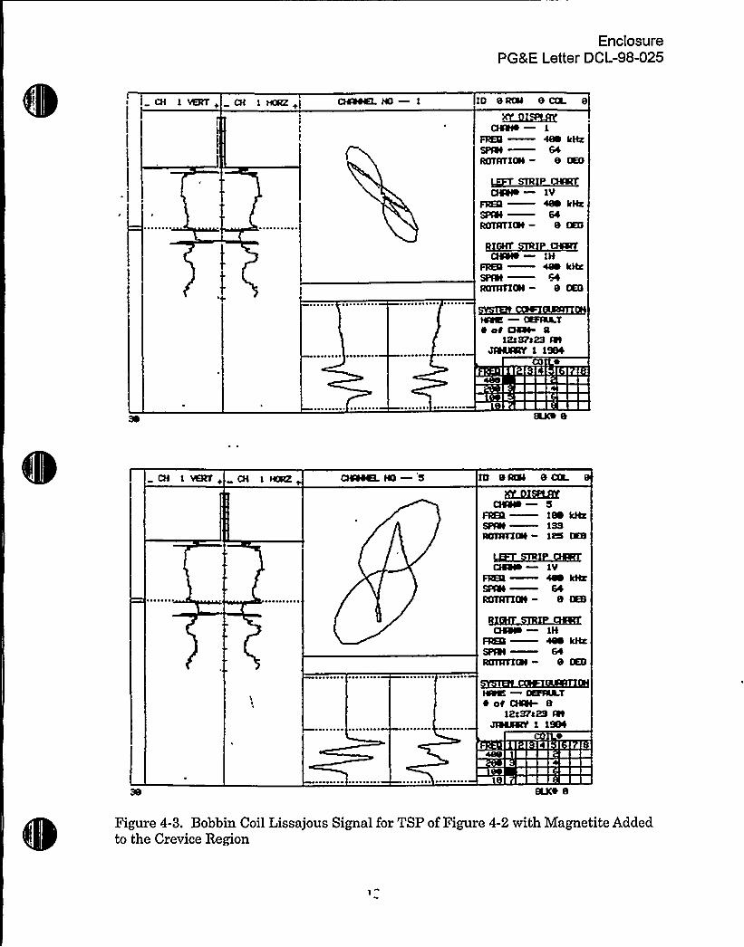
typical bobbin response as a figure 8 lissajous from a TSP with an open crevice and noTSP corrosion. Figure 4-2 shows distortion of the TSP lissajous obtained from a TSPwith a 20-mil deep, 1/4-inch wide, 360 degree circumferential groove machined in thecenter of the TSP. This signal response is typical of TSP corrosion signals thatpreceded development of dents in operating plants. The accumulation of high densitymagnetite in the crevice causes an interference or distortion in the TSP signal.Figure 4-3 shows the same TSP simulant as Figure 4-2, but the groove was filled withmagnetite. The "spike"-like signals represent the iron oxide influence and provideinsight to characterize a TSP intersection.
An example of the application of the above bobbin NDE techniques to characterize andmap TSP corrosion has been documented in Section 5.3 of Reference 4.1, which hasbeen previously transmitted to the NRC as part of the submittals supporting thealternate repair criteria for ODSCC at TSP intersections. These results show that NDEcan identify TSP corrosion and magnetite in about 80 to 100 percent of the hot legcrevices. Since it can be expected that all crevices are packed, the 80-percent NDEdetection of packed crevices represents the probability of detection of the packedcrevice condition.
Upon NRC approval of WCAP-14707, updated procedures for identifying denting,TSP corrosion, and magnetite in the crevice would be qualified using EPRI Appendix H
methodology against laboratory specimens. Plants planning to apply WCAP-14707 asthe basis for limited TSP displacement would then develop maps of TSP intersectionsdented or with the presence of TSP corrosion/deposits. These maps, together withtube/TSP breakaway pull forces for dented and for packed crevices, would be used todemonstrate that the crevice conditions provide significant margins against the SLBloads on the TSP such that TSP displacement is prevented. While NDE can identifycrevice conditions rather than tube-to-TSP contact forces, the large margins betweenthe load carrying capability of a packed or dented crevice and the SLB loads indicatethat additional direct measurements of the crevice resistance to pull force loads are notrequired.
NRC Question 5.
Discuss the methods used to ensure that all relevant worldwide data have beenobtained.
PG&E Response
To ensure that all relevant worldwide data have been obtained, a request was made byEPRI to the French, Belgian, Swedish, and Japanese requesting any available data onpull forces and leak rates measured for tube/TSP intersections. This inquiry did notidentify any other new data beyond a single data point from Ringhals 3 that waspublished (discussed below) since the preparation of WCAP-14707.
-6-

g'I
tf44 i
Vl a
'H
i
H'lI
,H
g,4
P

EnclosurePG&E Letter DCL-98-025
Reference 2.7 discusses crevice morphology for two tube/TSP intersections that wereremoved from Ringhals 3 as described in the response to Question 2. The crevicemorphology is very similar to that reported in WCAP-14707 for the Dampierre TSP
'ntersection.The breakaway force to displace the tube relative to the TSP wasmeasured for one TSP intersection with a measured force of 2,397 pounds. This resultis in good agreement with the Dampierre data provided in WCAP-14707.
Following preparation of WCAP-14707, an in situ leak test was performed on anindication (Plant A-1, 13.7 bobbin coil volt ODSCC) that was found, after tube removaland destructive examination, to have a 0.42-inch throughwall crack. The indication wasin situ tested at normal operating pressure differential and no leakage was obtained.The TSP crevice was packed but there was no dent deformation at the associated TSPintersection. This result provides additional support that packed crevices significantlyrestrict leakage potential.
No domestic utilities have removed intact tube/TSP intersections and measuredtube/TSP breakaway forces or leakage under packed crevice conditions. Tube/TSPintersections have been removed from McGuire-1 under an NRC program but, at thistime, breakaw'ay force measurements have not been performed or are not known to beplanned.
NRC Question 6.
In accordance with the staff's approach to riskinformed regulation, changes in licensingbasis are to be accompanied by an assessment of the associated potential for changesin risk. In view of future proposed changes to the design basis, address the implicationsfor tube integrity under severe accident conditions. Specifically, address the effect dueto defects leftin service.
PG&E Response
Back round and Introduction:
Based on an ARC addressing axial PWSCC indications at dented TSP intersectionswith a qualified NDE technique for sizing of indications, axially oriented flaws could beleft in service with depths exceeding the current Technical Specification repair limit.Current plans are to apply the limited TSP displacement analysis of WCAP-14707 to anARC for axial PWSCC indications within the bounds of the TSP. A later, separatesubmittal addressing axial PWSCC extending outside of the TSP appears technicallysupportable. The potential for a change in risk is expected to be reduced or similar tothe potential change in risk associated with application of GL 95-05 alternate repairlimits for axial ODSCC, previously evaluated by the NRC. The limited TSPdisplacement condition for the SGs is expected to reduce the severe accident risk forboth corrosion mechanisms compared to the open crevice condition of the SGs. This

I!
0

EnclosurePGRE Letter DCL-98-025
response is directed toward identifying the assessments that would be made to confirman acceptably low risk to support ARC for axial PWSCC located within dented TSPintersections.
An engineering assessment would be made to evaluate the crack exposure outside theTSP under severe accident conditions with the goal of demonstrating that the limitedtube-to-TSP displacement would not result in a large increase in burst probability orgross leakage. Most likely, restraint at dented intersections will remain, and burst andleakage probabilities will be greatly reduced compared to open crevice conditions. Apreliminary assessment of the tube integrity evaluation is described below as well asthe impact of the ARC on SG tube rupture probability.
In addition, to gain added insight into the implications for tube integrity under severeaccident conditions, PGRE is participating in an EPRI pilot program (Reference 6.1) todevelop the methodology to determine the frequency of SG thermal challenge followinga severe accident. The methodology being developed is expected to demonstrateacceptably low thermal challenge frequencies at Diablo Canyon Power Plant followinga postulated severe accident.
Potential Im act to Inferred S ontaneous Steam Generator Tube'u ture Probabilit
The application of the ARC for Axial PWSCC at dented TSP intersections is expectedto result in a condition such that the associated risk is not expected to changesignificantly and would be bounded by the risk due to application of the GL 95-05 ARCfor axial ODSCC at TSP intersections. The staff has cohcluded (Reference 6.2) thatthe application of GL 95-05 will not increase the spontaneous tube rupture frequencydue to (1) the deterministic requirements inherent to the criteria that are intended toprevent ruptures, and (2) the TSP constraint prevents ruptures during normal operatingconditions.
In the dented TSP ARC, it has been established that the axial constraint provided bythe denting condition will preclude TSP displacement relative to the tube during theblowdown phase of a postulated SLB event. Since the SLB is the limiting event forTSP displacement, TSP displacement is also precluded at normal operating conditionsand other design basis accident conditions. Therefore, the conditional burst probabilityat end-of-cycle conditions following application of the criteria will be several orders ofmagnitude less than the assumed conditional burst probability of 1 x 10'ssociatedwith the application of GL 95-05. The NRC staff has concluded (References 6.2, 6.3)that with an assumed conditional burst probability of 10'nd given a rapiddepressurization of the secondary side, that core damage frequency contribution isacceptably low. In addition, the NRC staff concluded (Reference 6.3) that SG tubeperformance would not be significantly impacted as a result of axially oriented ODSCCat TSP elevations and, therefore, high pressure severe accident analyses would not beaffected. The core damage frequency due to application of the dented TSP ARC will
-8-
g
i' '
t
A
~ ~ 4
EnclosurePG&E Letter DCL-98-025
therefore be significantly below the level currently implied by the 10'urst probabilityfor application of the ARC for ODSCC at TSP intersections.
Furthermore, consistent with NRC positions presented to the ACRS, primary-to-secondary leakage under design basis accident conditions is expected to be within theNRC-approved allowable leakage limitand well less than the normal charging capacity.It is concluded that application of the PWSCC ARC will not increase the overall coredamage frequency.
Tube Inte rit Considerations for Postulated Severe Accident Scenarios
Axial PWSCC indications within the TSP are not expected to result in a significant tubeburst probability or leakage, even in the event that core uncovery occurs. In thisscenario, the hot leg is expected to fail by a creep rupture phenomena, therebyeliminating the thermal challenge to the SG tubes.
Even if the hot leg is assumed to remain intact and increased thermal conditions arepostulated for the SG tubes, the restraint forces (which prevent TSP displacementduring a SLB event) from the dented TSP intersections would be expected to remain atmost TSP intersections. This results in the TSP providing similar constraint to thatduring normal operating and design basis accident conditions. These constraint effectswould therefore similarly greatly reduce the potential for an increase in burst probabilityand leak rate. At such postulated thermal conditions, the reduced material propertiesof the TSPs and stayrods would be expected to result in tube/TSP contact forcescausing large TSP/stayrod deflections. The load applied to the TSPs and stayrods bythe tubes due to thermal growth would significantly exceed the resisting force due tothe out of plane stiffness of the TSPs. Therefore, residual burst and leakage constraintwould be expected to be provided even under postulated severe accident thermalconditions for all TSP elevations. The TSP proximity during these conditions would actto prevent burst and greatly reduce leakage potential by preventing opening of thecrack face. Upon approval of WCAP-14707 and submittal of an ARC, this expectedbehavior under the severe accident thermal conditions can be analyzed with thedetailed structural model used for the WCAP-14707 TSP displacement analyses.
,The tubes in the immediate vicinity of the wedges are the only tubes that may representa potential for flaw extension beyond the TSP due to tube thermal growth and theincreased stiffness of the TSP in the wedge regions. Large axial loads are expected tobe applied to the TSP stayrods during the event due to tube thermal growth mismatchwith the stayrods. It is expected that the dynamics of this configuration would result inthe TSPs moving with the tubes, even in the stayrod regions, and therefore providingthe proximity restraint that essentially precludes burst and greatly reduces leak rates.The majority of dented TSP axial PWSCC indications are concentrated at the first threeTSPs. Under postulated severe accident temperature conditions and assuming theTSP restraint from dented TSP intersections is lost near wedges, tube axial growth
-9-
/
EnclosurePG8 E Letter DCL-98-025
relative to the lower TSPs due to the thermal conditions is expected to result insubstantial TSP proximal constraint applied to crack indications originally located withinthe TSP. This constraint effect acts to "shorten" the effective length of exposed axialflaws due to crack tip restraint within the TSP.
In conclusion, the displacement restraint characteristics of the packed/dentedintersections are expected to remain during plant response to a severe accident, andthe proximity constraint provided by the TSP during normal operating conditions willalso be present during the event. The TSP constraint greatly reduces the burstpotential of indications left in service by application of the ARC, and similarly reducesthe potential for significant primary-to-secondary leakage;
-10-
Qs
C
pf
EnclosurePGKE Letter DCL-98-025
REFERENCES
"Industry Database for Steam Generator Tubing Outside Diameter StressCorrosion Cracking at Tube Support Plates (Project No. 689), Letter R. C.
Callaway, Nuclear Energy Institute, to Document Control Desk, U.S. NuclearRegulatory Commission, November 20, 1997
2.1 "The ASME Handbook on Water Technology for Thermal Power Systems," PaulCohen, Editor-in-Chief, The American Society of Mechanical Engineers, NewYork, NY, 1989, pp 279-340
2.2 Ibid., pages 302-303
2.3 Ibid., page 301, Figure 6-36
2.4 Gupta, K. K., et al., "Diablo Canyon Unit 1 Steam Generator Tube Examination,"Westinghouse STC 96-5TC5-SGDCN-R1, July 16, 1996, Figures 2-1 a to 2-7d
2.5 Albertin, L., et al., "Characterization of Crevice Deposits in the Dampierre Unit 1
Steam Generator Tube Support Plate Assembly," Westinghouse STC 94-7TE2-DAPER-R1, November 30, 1994
2.6 Morgan, E. P., et al., "Examination of Denting and Characterization ofAssociated Materials in the Plate-Tube Intersections of Westinghouse NuclearSteam Generators," Westinghouse STC 76-7D2-SGEXM-P1, September 27,1976
2.7 Lancha, A. M., et al., "Characterization of Ringhals 3 TSP Crevice and TubeDeposits," Eighth'International Symposium on Environmental Degradation ofMaterials in Nuclear Power Systems —Water Reactors, August 10-14, 1997
4.1 WCAP-12871, "J. M. Farley Units 1 and 2 SG Tube Plugging Criteria for ODSCCat Tube Support Plates," February 1991, Westinghouse Electric Corporation
6.1 Fuller, E. L., et al., "Assessment of Risks from Thermal Challenge to SteamGenerator Tubes During Hypothetical Severe Accidents: Diablo Canyon as anExample Plant," Draft Report, September 1997, EPRI Project S550-18
6.2 Official Transcript of Proceedings, Nuclear Regulatory Commission AdvisoryCommittee on Reactor Safeguards, Materials and Metallurgy Subcommittee,Presentation of Mr. Long, August 3, 1994
-11-
EnclosurePG&E Letter DCL-98-025
6.3 NRC Memorandum to Brian Sheron from Themis P. Speis, "Office of ResearchConcurrence on Generic Letter (GL) 95-XXVoltage Based Repair Criteria forWestinghouse Steam Generator Tubes Affected by Outside Diameter StressCorrosion Cracking," Attachment 3, Section 3.2, May 3, 1995
-12-


EnclosurePG&E Letter DCL-98-025
CH 1 CH IO eau 8 cQ.X~Y
FREQ-SPAI—ROTATI&l-
Qiele —lyFRY —ea kmSRN-ROTATIQt — e ~
QCNO— ~ kHeSFlN —SlROTATIQI — e Ixs
NO% —%PANT~ ot DCSt 8
1Raeea88 NlJRRSIR 1 1988
L.
1 ~+ CH l tCRZ ~
5LRUKLfKWHO 5
FREQ —188 kHgSPAI —13$ROTATIlll- its ITS
F18 —1VFREQ ~ kHzSFlll—64RoTATIm - e ma
QIII8 lHFREQ —400 k8aSPlet —64ROTATIVE — 8 %8
~ —lÃFIRAT~ of CASE 8
12a89l5 QfJ18RÃIK 1 1980
Figure 4-1. Bobbin Coil Lissajous Signal for TSP with No Degradation or Magnetite

EnclosurePGRE Letter DCL-98-025
CH l VERT+ CH m 8RIII 8amQIRLfK
CAW+ —1
FREQ —480 kiteSPQI 64enmlaS - 8 me
CHOIR 1VFREII 4iN kHzSPQI 64RIIITl04 — 8 tKG
CAW+ —lHFREIl 400 kHzSPQt —64RMATIQI- 8 %8
IXAkIT~ ot GQt. Ia
l2aQSaM QIJRESSR 1 1
RKO 8
CH 1 VERI'+ CH 1 HlaZ CHOIKK. le 5
KUHRXSZQIII8 —S
FREQ il kHzSPQt 13$ACMCICN — MS (AS
CH5% —1VFRY —~ kHzSPQI —64ROAPIQt - 8 (KB
Q40% —lHFRKQ 4QO kHzSPQI —64RCTAVIDI — 8 %B
l4%% —fXFHL.T8 cH'48t- 8
12a8$ c~ AtJFMSRY 1 1984
are 8
Figure 4-2. Bobbin Coil Lissajous Signal for a TSP with a 20 mil Deep, 0.25" Wide360 Degree Groove in Center of TSP
d x
EnclosurePG8 E Letter DCL-98-025
CH 1 VERT i CH 1 HRZ+ 10 Sl5%0 8 DX 8
X~Y
CIIN+ —1
FREQ —~ kHzSPNI —64RGTATIQI — 8 tKS
CIIW+ —1VFREQ ~
kIh.'R%I—64ROITIIm — 8 mS
CIIII+—1HFREQ —44M kHzSPQI —64ROTATIQI — 8 [KG
N%% lRF%L.T~ c<C CIIII 0
1Rs3Fa23 INJIMMY 1 1~
CH 1 VERT ~
5L2lRLBXCISII8 S
FREQ —1M kHxSPIII—13$ROTATIOI — il5 III
CIIII8—1VFREQ —~ kyarSPIII—64RGTATIRt — 8 I%8
CHSIO —1HFREQ —488 kHzSPIII—64ROTATIIN — 8 (KB
IXPVRR.T~ oC CHOt- 8
iea3Fc2$ I8IJ$5k~ 1 1984
Figure 4-3. Bobbin Coil Lissajous Signal for TSP of Figure 4-2 with Magnetite Addedto the Crevice Region

1 ' 4
8,)"l
,SII
1
~ .
I'
.Attachment 1
PG&E Letter DCL-98-025
SUPPLEMENT TO THE RESPONSE TO NRC QUESTlON 2
Drilled TSP Hole Crevice Conditions
The technical basis for concluding that the tube support plate (TSP) crevice conditionfor drilled hole steam generators (SGs) is represented by a crevice with deposits thatprovide significant resistance to axial displacement is grounded in field and laboratorydata and the physical principles of crevice behavior in a heat transfer environment.This supplement to the response to NRC Question 2 develops the following topics:
~ What does an operational crevice contain?~ Why are water chemistry variations between plants not expected to be a major
variable?~ What is the influence of chemical cleaning'?~ What differences in crevice morphology and resistance to axial displacement would
be expected between shutdown, operational, and steam line break conditions?
What does an operational crevice contains
Several opportunities to study the tube-to-TSP crevice have been provided by theremoval of intact sections from either operational or retired SGs. One such opportunityarose from the retired SGs of the Dampierre 1 plant in France. These SGs weregenerally of the Westinghouse design and manufactured under license by Framatome.They were designated as Model 51M SGs. Although there were some non-Westinghouse design modifications to the SGs, the tube-to-TSP crevice geometry isessentially unchanged from the Westinghouse design and the results described beloware considered representative of the class of similar SGs.
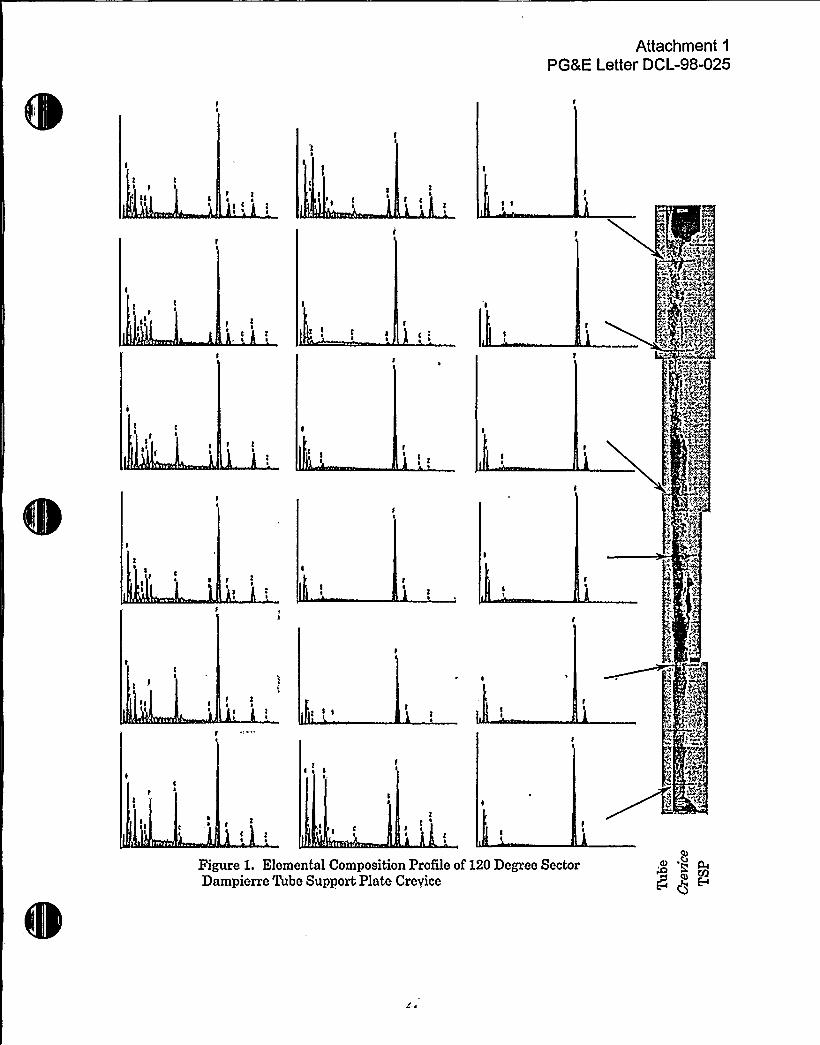
Figure 1 shows, on the right side of the figure, a photographic reproduction of themetallographic, axial cut, cross, section of a crevice from the Dampierre 1 retired SG asit was examined at the tube examination facilities of Westinghouse Electric Company.This intersection was not dented. The photograph shows just the edge of the outsidediameter (OD) of the Alloy600 MAtubing on the left, the adjacent crevice deposit, andon the far right, a portion of the carbon steel of the TSP. The eighteen spectraportrayed in six rows of three are from the energy dispersive X-ray (EDS) spectroscopicexamination of the crevice deposits immediately adjacent to the tube (left column), inthe central region (middle column), and adjacent to the TSP (right column). Theapproximate corresponding axial position of each row is designated by a referencearrow to the metallographic cross section. The data provided show that the elementaldistribution within the crevice favors the concentration of silicon, phosphorous, zinc,aluminum, magnesium, iron, and oxygen containing deposits in the layer adjacent tothe tube and across the width of the crevice at both the upper and lower openings.Other species such as copper and sulfur are also reported. The central region of the

p,tC
'l
Attachment 1
PGKE Letter DCL-98-025
crevice, both axially and radially, is predominantly filled with compounds formed fromiron and oxygen. Supporting data in the form of electron probe microanaiysis providean area map of the elements and shows regions, for example, with common elementsoccupying the same area, supporting their presence there as compounds. In addition,X-ray diffraction analysis was performed to determine crystal structure, with the reportof crevice compounds such as magnetite (Fe~O~), hematite (Fe>O>), silicon dioxide(SiO>), manganese oxide (Mn~O>), willemite (Zn~SiO~), calcium phosphate hydrate(Ca>(PO~)~nH~O), xonotlite (Ca<Si~O<7(OH)~), goethite (FeO(OH)), and others.
The combined data show that this crevice contains a mineral matrix compositeincluding iron oxides adjacent to the tube, with a gradual radial transition topredominantly iron oxides adjacent to the TSP.
Another section of the same TSP location on the opposite side of the tube (300 degreeversus 120 degree angular position) is shown in Figure 2. Although only a few areasare shown for this position, it can be seen that the results are the same. In addition,the photographs of the respective deposits reveal the interlaced composite formationadjacent to the tube and the transition to predominantly iron oxides adjacent to theTSP.
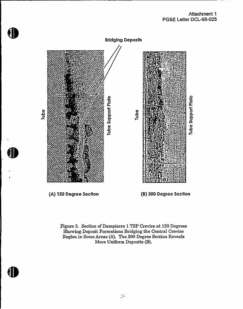
The porosity of the deposits adjacent to the tube and the TSP is low, i.e., in the rangeof 1 to 10 percent void. The central region of the 120 degree section has a higherporosity, ranging to 50 percent void (see Figure 1). The corresponding region of the300 degree section has no corresponding void space (see Figure 2). This variation inporosity may represent the operational crevice condition or it may be an artifact ofsample preparation. There is a possibility, for example, that the cutting and polishingoperations resulted in some crevice material dropouts that contributed to this apparentporosity. This is partly supported by examination of the micrographs, which showregions were the deposit forms bridges across the crevice with adjacent and irregularvoid patterns suggestive of material that dropped out. Figure 3 shows this in anenlargement of a portion of the 120 degree section.
Another possibility is that steam chimneys formed in a portion of the crevice andcontributed to the porosity. An example of such porosity was observed in a TSPsection removed from Turkey Point 4, Steam Generator C, in 1976 while the plant wasstill operational, as shown in Figure 4. The particular TSP intersection shown was cutaxially for one sample and then the remainder was polished in the direction of the faceof the TSP to provide the metallographic sample illustrated in Figure 4. Dentingmagnetite has formed over the entire circumference of the crevice boundary, and thetube was uniformly dented, in the radial direction, by the forces exerted by thiscorrosion product. A region of exceptional morphology exists, just to the right of the180 degree location, on the sample at the top of the figure. This area is enlarged in thecutaway and shows a porosity that is believed to exist as a result of a "steam chimney"in the crevice that allowed refreshment of secondary side contaminants to concentrate
-2-

L (
Attachment 1
PGLE Letter DCL-98-025
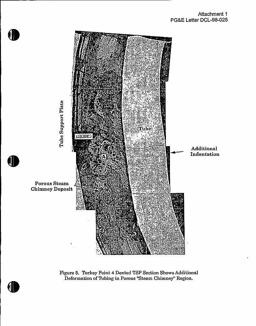
in this region and resulted in a higher corrosion rate. This corrosion rate is reflected inthe greater recession of the carbon steel surface of the TSP, as well as the additionaldeformation that forms an indentation on the already dented profile of the tube, asshown in Figure 5. Incidentally, this also shows that porosity is not synonymous withcompressibility, at least not at the levels required to deform SG tubing.
Although the microanalytical techniques of the late 1970s were not quite assophisticated as those available for tube examinations today, the EDAX (energydispersive analysis by X-ray) technology of Figure 6 shows that the elementaldistribution in the crevice placed mineral forming compounds adjacent to the tube wall,with iron oxide on the TSP side of the crevice.
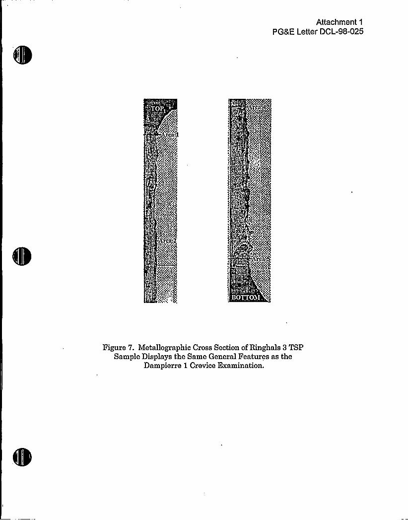
A more recent characterization of a tube and TSP crevice intersection was performedon a drilled hole crevice of the Ringhals 3 plant. This Model D3 preheat SG hasessentially the same tube-to-TSP crevice configuration as the Model 51 series (seeFigure 7). That report provides a view of the crevice that is packed with deposits togreater than 90 to 99 percent density for most of the crevice regions, with a fewlocations, particularly on the 0 degree section, ranging to about 50 percent porosity.Radial distribution of species such as zinc, manganese, and silicon were preferentiallyhigh in the crevice region adjacent to the tube. These decreased in quantity as theTSP surface was approached and as the concentration of iron oxide compoundsincreased. Magnetite, a chromium substituted oxide, and zinc silicate were reportedbased on the X-ray diffraction examination of crevice deposits. The tube-to-TSPbreakaway force was measured in the laboratory and determined to be essentially thesame as that measured for Dampierre 1.
Both of these evaluations support the common theme of crevice deposit composition asbeing a mineral rich composite formation in the vicinity of the tube with a highercomposition of iron oxides adjacent to the TSP. This occurs because the heat transferconditions at the tube surface provide an available superheat over the saturationtemperature of the bulk water. If a clean crevice were assumed to be the startingcondition, the flow of water into the crevice would carry with it a proportion of thesuspended solids circulating in the SG and also some soluble material in the form ofadditives and contaminants. Since the crevice conditions are confined and the surfaceof the TSP provides an additional surface for deposition of particulate material, thedeposits soon build up in a manner similar to that on the free tube surface. Thedeposits are porous at the beginning and provide a matrix for water to work its way
to'he
tube and for steam, with its greater volume per unit mass, to move from the crevicethrough steam chimneys. Since most common SG solutes, such as sodium, chloride,
'ulfates,silicates, and phosphates have a lower solubility in the steam phase than inthe liquid phase, the concentration of solutes increases in small liquid pockets that formin the matrix of porous deposits. These liquid pockets exist because of boiling pointelevation that occurs due to the vapor pressure lowering from the increasingconcentration of solute. For most SG solutes, the solution will become saturated in
-3-
/w
P v
'4
0

Attachment 1
PG8 E Letter DCL-98-025
mineral content and the solution will begin to precipitate whatever phases can nolonger be held in solution. (Sodium hydroxide, ifpresent among these components, willremain in solution and contribute to corrosion.) The continued ingress of many of theSG solutes, however, would tend to mitigate against the continued long-term stability ofsubstantial quantities of sodium hydroxide by providing a buffer for the crevice. Asthese deposits form, the species that are more volatile, e.g., organic acids and mineralacids such as HCI, are carried out of the crevice with the steam. The steam channelswould provide a mechanism to carry low concentrations of mild carbon steel corrodantsto the surface of the carbon steel TSP in the crevice. This would further contribute to alow level of carbon steel corrosion and the production of iron oxides. (In cases wherethe concentration of HCI is excessive, the carbon steel may corrode at an acceleratedrate and produce denting.) The mass transport, concentration, and precipitation cyclecontinues as the crevice loses porosity and the ability to freely communicate with thebulk water is reduced. In the case of the Dampierre 1 crevice, it would seem that thecrevice essentially becomes sealed with an encrustation of precipitated mineraldeposits that form across the openings of the crevice.
Since these principles of mass transport and heat transfer are common to all similardrilled hole crevices operating on the hot leg of the SG, all such crevices would beexpected to behave in a similar fashion.
'hy
are wafer chemisfry variafions befween plants nof expecfed fo be a majorvariables
Although the rate of crevice packing and the exact nature of the mineral deposit will, ofcourse, vary somewhat with plant-specific water chemistry, the ultimate creviceconditions will end up being similar. One common feature will be iron oxides comingfrom both the feedwater system and internal SG sources. Silica is a ubiquitouscomponent of secondary-side water and is found in all plants. Silicon compounds willaccordingly be commonly found in crevices. Manganese most likely has origin in thecorrosion of the steel and is also generally observed. These species alone aresufficient to form a strong crevice matrix adjacent to the tube.
The iron of the carbon steel TSP also oxidizes, and in situ iron oxide growths from thecarbon steel TSP will necessarily be formed and contribute to crevice packing.
Plants with ODSCC corrosion occurring in the TSP crevice region have, by definition,produced concentrated aggressive contaminants capable of initiating that corrosion.These aggressive species cannot simply separate themselves from other dissolved andsuspended species and concentrate in the absence of. other components. The mineralspecies described earlier are also undergoing concentration in the same time frame ina manner consistent with their concentration and the thermal and hydrauliccharacteristics of the crevice. The continued precipitation of mineral species adjacentto the tube surface and the reduction in porosity, with its associated reduction in mass

I
lc
gl ~
Attachment 1
PGRE Letter DCL-98-025
transfer rates, eventually results in chemical buffering and a 'ully packed" crevice withlittle ability to allow mass flow in or out.
Observations to extend this plant documented crevice packing condition to othercrevice locations are amply provided in the many tube examinations that have beenperformed over the past years. If the crevices universally contain a relatively adherentmineral precipitate adjacent to the tube, then the residual of these deposits should beobserved at the TSP regions, even after all of the rigors of a tube pull. Typically mosttubes are removed by being pulled through the 21 inches of a relatively close-fittingtubesheet hole, as well as other TSP crevice locations. This process would beexpected to dislodge all but the most adherent of deposits. The TSP crevice region,however, is generally easily recognized visually because of its unique bandedappearance and/or the presence of residual deposits. These deposits have beenanalyzed on many occasions and are completely consistent with the crevice formationdeposit model described herein. One recent tube pull examination for Diablo CanyonUnit 1, Steam Generator 2, showed tube adherent TSP 1 and 2 deposits containingcalcium, magnesium, silicon, aluminum, manganese, and zinc. Specific crevicecompounds identified by X-ray diffraction were magnetite, copper, aluminum silicatehydroxide, and possibly magnesium and iron silicate hydroxide phases.
Furthermore, deposits located at the uppermost or lowest TSP crevice of the hot leghave generally similar characteristics with respect to the mineral deposits and chemicalcomposition. The Turkey Point 4 TSP crevice examination and the Dampierre 1
crevice examination occurred with upper level TSP crevices. Most of the completelyconsistent tube pull deposit information of interest occur from lower TSP locations,since these are typically subject to more ODSCC due to the higher temperature andhigher available superheat at the lower TSP crevice regions.
The major difference that would be expected to occur as a result of water chemistry onthe formation of packed TSP crevices is the rate of deposit buildup that would allow theinitial concentration processes to occur. This would be a strong function of thecorrosion transport processes in the overall plant. If a plant operated with extremelylow dissolved and particulate transport iron, the rate of tube deposit formation would beextremely slow. Correspondingly, the rate of crevice packing would also be slow.Conversely, such a plant would not be expected to be experiencing any significantamount of tubing corrosion at the TSP, since a concentration mechanism is notoperative. In this sense the actual operational time of a SG is not the sole determiningfactor in the crevice packing condition. Some SGs have dented in the first cycle ofoperation and others (a very small population) have operated for many cycles with lowdeposit inventories and no signs of the concentration processes, e.g., hideout return,that are suggestive of packed crevices.
-5-
II
l J V~
h I H
i I
Attachment 1
PG8 E Letter DCL-98-025
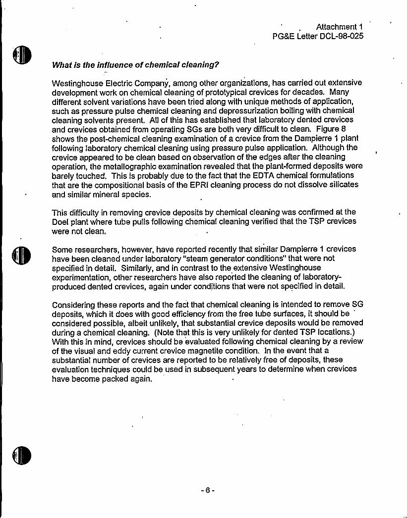
What is theinfluence of chemical cleaning'
Westinghouse Electric Company, among other organizations, has carried out extensivedevelopment work on chemical cleaning of prototypical crevices for decades. Manydifferent solvent variations have been tried along with unique methods of application,such as pressure pulse chemical cleaning and depressurization boiling with chemicalcleaning solvents present. All of this has established that laboratory dented crevicesand crevices obtained from operating SGs are both very difficultto clean. Figure 8
shows the post-chemical cleaning examination of a crevice from the Dampierre 1 plantfollowing laboratory chemical cleaning using pressure pulse application. Although thecrevice appeared to be clean based on observation of the edges after the cleaningoperation, the metallographic examination revealed that the plant-formed deposits werebarely touched. This is probably due to the fact that the EDTA chemical formulationsthat are the compositional basis of the EPRI cleaning process do not dissolve silicatesand similar mineral species.
This difficulty in removing crevice deposits by chemical cleaning was confirmed at theDoel plant where tube pulls following chemical cleaning verified that the TSP creviceswere not clean.
Some researchers, however, have reported recently that similar Dampierre 1 creviceshave been cleaned under laboratory "steam generator conditions" that were notspecified in detail. Similarly, and in contrast to the extensive Westinghouseexperimentation, other researchers have also reported the cleaning of laboratory-produced dented crevices, again under conditions that were not specified in detail.
Considering these reports and the fact that chemical cleaning is intended to remove SGdeposits, which it does with good efficiency from the free tube surfaces, it should be
*
considered possible, albeit unlikely, that substantial crevice deposits would be removedduring a chemical cleaning. (Note that this is very unlikely for dented TSP locations.)With this in mind, crevices should be evaluated following chemical cleaning by a reviewof the visual and eddy current crevice magnetite condition. In the event that asubstantial number of crevices are reported to be relatively free of deposits, theseevaluation techniques could be used in subsequent years to determine when creviceshave become packed again.
-6-
I* s'Ifl
0Cp)
+I1
0
'I
<4<~ ~ II ~ g
I
Ir
I'
~, 4( „
Attachment 1
PG8 E Letter DCL-98-025
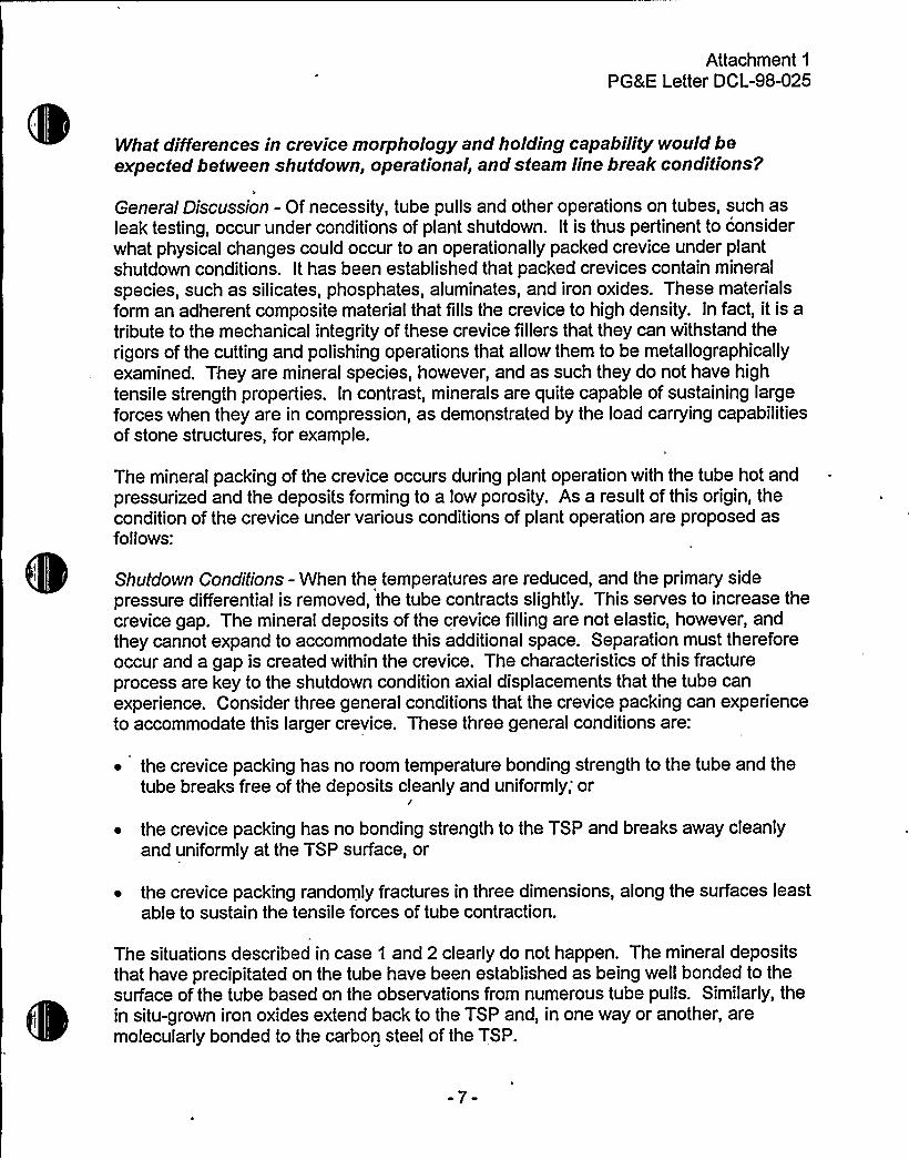
What differencesin crevice morphology and holding capability would beexpected between shutdown, operational, and steam line break conditions'
General Discussion - Of necessity, tube pulls and other operations on tubes, such asleak testing, occur under conditions of plant shutdown. It is thus pertinent to considerwhat physical changes could occur to an operationally packed crevice under plantshutdown conditions. It has been established that packed crevices contain mineralspecies, such as silicates, phosphates, aluminates, and iron oxides. These materialsform an adherent composite material that fills the crevice to high density. In fact, it is atribute to the mechanical integrity of these crevice fillers that they can withstand therigors of the cutting and polishing operations that allow them to be metallographicallyexamined. They are mineral species, however, and as such they do not have hightensile strength properties. In contrast, minerals are quite capable of sustaining largeforces when they are in compression, as demonstrated by the load carrying capabilitiesof stone structures, for example.
The mineral packing of the crevice occurs during plant operation with the tube hot andpressurized and the deposits forming to a low porosity. As a result of this origin, thecondition of the crevice under various conditions of plant operation are proposed asfollows:
Shutdown Conditj'ons - When the temperatures are reduced, and the primary sidepressure differential is removed, the tube contracts slightly. This serves to increase thecrevice gap. The mineral deposits of the crevice fillingare not elastic, however, andthey cannot expand to accommodate this additional space. Separation must thereforeoccur and a gap is created within the crevice. The characteristics of this fractureprocess are key to the shutdown condition axial displacements that the tube canexperience. Consider three general conditions that the crevice packing can experienceto accommodate this larger crevice. These three general conditions are:
~ the crevice packing has no room temperature bonding strength to the tube and thetube breaks free of the deposits cleanly and uniformly; or
/
~ the crevice packing has no bonding strength to the TSP and breaks away cleanlyand uniformly at the TSP surface, or
~ the crevice packing randomly fractures in three dimensions, along the surfaces leastable to sustain the tensile forces of tube contraction.
The situations described in case 1 and 2 clearly do not happen. The mineral depositsthat have precipitated on the tube have been established as being well bonded to thesurface of the tube based on the observations from numerous tube pulls. Similarly, thein situ-grown iron oxides extend back to the TSP and, in one way or another, aremolecularly bonded to the carbon steel of the TSP.
-7-

tQ
t
h
Attachment 1
PGRE Letter DCL-98-025
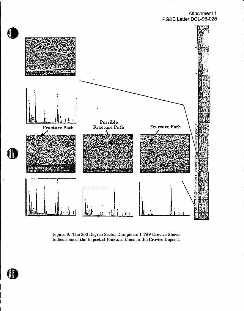
Logically, the mineral composite known as crevice packing deposits would be expectedto fracture in the same manner as their larger scale counterparts experiencingexpansion and contraction in nature, i.e., along the complex three-dimensional surfacesleast able to sustain the tensile forces. Fortunately there are some examples of thesefracture paths that can be observed in the crevice examinations. Three of the fourmicrographs in Figure 9 (a slight modification of Figure 2) show fracture paths orprobable fracture paths. A more complex example is shown in Figure 10, where thefracture paths, through the magnetite formed during the denting process, are decoratedwith nickel and silicon species. The result of these fracture patterns is that some slightmotion would be accommodated upon the application of an axial force. It would beexpected that the fracture surfaces would move slightly with respect to one another andthe nonplanar interfaces would begin to act on one another like a series of intertwinedwedges. As more and more force is applied, particularly applied dynamically as in atube pull, the compressive loads developed by the randomly inclined fracture surfacesincrease in magnitude. The deposits resist substantial displacement until finally theleading surfaces begin to crumble, starting the chain reaction deposit failure that allowsthe tube to break free of the crevice. On the other hand, sustained static loads, suchas those that may develop as a result of tube deformation in a repair process, are mostlikely relieved over the long term. This is accommodated with the lubricating effect ofwater and the ability of the particulate materials along the fracture faces to be displacedand move slightly with respect to one another, while the plant is in the shutdowncondition.
Returning to Power Operation - As the crevice, with its fractured surfaces, now perhapsslightly displaced with respect to one another or with a foreign particle lodged in place,is repressurized and returned to service, it closes the gaps that were produced duringshutdown. This accommodation may not be completely straightforward if the surfaceshave interference particles present. These particles may be incorporated into thecomposite if there is space available, thereby reducing the apparent porosity. Incontrast, the particles may be crushed and distributed along a fracture surface, leavinggaps that form a flow path for the migration of steam or water that contributes to themass transport properties of the crevice. Or, in the case of a dented plant, the inabilityof the crevice to return to its original configuration may result in some additional tubedeformation.
In any event, it is difficultto imagine that the crevice packing would be in anyconfiguration other than the original tight but not compressed packing configuration ora slightly compressively loaded variation of the original configuration.
Steam Line Break Conditions - As previously discussed, the general crevice conditionduring normal operation is concluded to be tight. The crevice deposits havedemonstrated good cohesiveness, not only as a crevice packing, but also as bondingagents to the tube and TSP. They are well protected from mechanical disturbance inthe long and narrow confines of an operating crevice and cannot be readily dislodged.
-8-
r'3'

IIIAttachment 1
PGRE Letter DCL-98-025
With this general set of conditions, which is well supported by numerous tube pulls andexaminations, the only plausible scenario is that the increasing primary-to-secondary
. side pressure differential willfurther compress the crevice packing. This increasedcompression would further lock the TSP in position and should result in tighter bondingthan would be displayed for the shutdown condition of the tube pull.
-9-
1
Attachment 1
PGRE Letter DCL-98-025
ICI
'I II
I ~
I ~ I
I
I
II
s I
Is I
II
I II
~ ~
II~ ~
II
II C
I
I III
3
/ 0
lI II ~
I II
I s I
C
II
II ~
Figure l. Elemental Composition Profile of 120 Degree SectorDampierre Tube Support Plate Crevice

P

Attachment 1
PGRE Letter DCL-98-025
C'-.'j/I
1
CICC~ ~
C
I ~
CCI I II
II
C II~ 11 CC
I I 'cI . I
I C
I
C
CI
&
44
tt't'CC
~:->9C
AQf
Figure 2. Elemental Composition Profile of 300 Degree SectorDampierre Tube Support Plate Crevice
Attachment 1
PG&E Letter DCL-98-025
Bridging Deposits
a
0O.CLD
[jh$
(A) 120 Degree Section (B) 300 Degree Section
Figure 3. Section of Dampierre 1 TSP Crevice at 120 DegreesShowing Deposit Formations Bridging the Central CreviceRegion in Some Areas (A). The 300 Degree Section Reveals
More Uniform Deposits (8).
'
e"
)1
kt

Attachment 1
PGRE Letter DCL-98-025
A: p
'* gggq g
"Porous" Steam Generato r Deposits
Denting Magnetite
Figure 4. Crevice From Dented. Steam Generator EstablishesThat "Porous" Steam Generator Deposits Sustain
Denting Forces

(
1l
Attachment 1
PG8 E Letter DCL-98-025
IPN
0QcS4'
I
<A'+*AdditionalIndentation
Porous SteamChimney Deposit P„";
kp.;
Figure 5. Turkey Point 4 Dented TSP Section Shows AdditionalDeformation of Tubing in Porous "Steam Chimney" Region.

1

Tube
Attachment 1
PG8 E Letter DCL-98-025
TSPpg",„-~~,', ~~~~ 'hVO)020'!-'»
Q;TJ
~~+ "" 346 f>3.'ifviii~5i4.";".'jj+~i~+
Figure 6. Micrographs and Energy Dispersive X-rayAnalysis Shows Mineral Forming Elements in the
Crevice Region Near the Tube and Iron Oxide Compositionin the Denting Region Closer to the TSP.
(Turkey Point 4 Dented Tube Support Plate Examination)
Attachment 1
PGRE Letter DCL-98-025
Figure 7. Metallographic Cross Section ofRinghals 3 TSPSample Displays the Same General Features as the
Dampierre 1 Crevice Examination.
0

Attachment 1
PG8 E Letter DCL-98-025
I I~ i t~ I
C ig
Top
!q~qj g
iec,,f ~gag
p
4:y'PH~t'f'
I ~
Middle
c
I','i z
«$ t
, gc$
g~4
TubeBottom TSP
Figure 8, Cross Section Crevice Examination ofDampierre 1 Tube Support Plate Specimen
Following Chemical Cleaning Test

'4
Attachment 1
PGRE Letter DCL-98-025
t
vg "<'
I(
IC sC~ ~
Fracture PathPossible
Fracture Path Fracture Path
h
4a
*P
s rmy
gag"Y
~~" 4t
lCt C'
I II
cI
Figure 9. The 300 Degree Sector Dampierre iTSP Crevice ShowsIndications of the Expected Fracture Lines in the Crevice Deposit.
1
C
Cw
f'
~V

V
-!C
-wow~;4 J.
CI
e;o'Weg~e'~~w$ ww ',«wy A~~+, ~~>+~~M~gW+g.w+wp
'SE
.. '+ g" Nl, - ':e Cl
P3
e
jj,'u„:,', ', Sl
Cu-
" ''TUBE' .".> -',*
+~/qPp+P~) ~ Qg
e'epe+M4 +, +;.+
C
Hl CI Cu
K&qTT
LsNoSI ~j9@ ~j; P
w*.m w m~~~ 'ee
Ei
k.~:W' a'M WMm~
A,
Ifl
~g, W eehghoeoe Reseich Gbxeeorlee,. »«~ lllll~ 11I4 tlsalTltamla" I ~I\~ '
e
'/
AI
Figure 10. Fracture Paths in the Turkey Point 4 Dented CreviceSample Are Decorated with Contaminant Species Such as
Ni, Si, Cr, Cl and Cu.
Attachment 2PGRE Letter DCL-98-025
References 2, 3, and 4 of WCAP-14707,"Model 51 Steam Generator Limited Tube Support Plate Displacement Analysis
for Dented or Packed Tube-to-Tube Support Plate Crevices"
Reference 2
Electricite de France Report D.5716/CTT/RB 94.6129, "Pressurized Water Plants,Steam Generator, Some Applications of Leak Flow Rate and Burst Tests Performed onPulled Tubes in Evaluation of the Operating Safety and Reliability of the Tube Bundle,"dated July 8, 1994
Reference 3
Electricite de France Report D.5716/CTT/RS 94.6124, "Pressurized Water Plants,Steam Generator, Results of Leak and Burst Tests Performed on Pulled Tubes," datedAugust 10, 1994
Reference 4
Westinghouse Electric Corporation Application for Withholding Proprietary Informationfrom Public Disclosure (Henry A. Sepp to Document Control Desk), CAW-98-1211,dated February 23, 1998.
Proprietary Information Notice
Copyright Notice
AffidavitCAW-98-1211 of Henry A. Sepp, Manager, Regulatory and LicensingEngineeiing, Nuclear Services Division, Westinghouse Electric Corporation, datedFebruary 23, 1998.
Westinghouse Science and Technology Report 94-7TE2-DAPER-R1, "Characterizationof Crevice Deposits in the Dampierre Unit 1 Steam Generator Tube Support PlateAssembly," dated November 30, 1994 (PROPRIETARY)

l4
'h e~ g H S
s t„k" 'j