Catastrophic Line Leak Detection, PowerPoint … · Automatic Line Leak Detectors “Methods which...
44
Quality Petroleum Equipment Solutions for Over 20 Years LDT-890 & LDT-890\AF
Transcript of Catastrophic Line Leak Detection, PowerPoint … · Automatic Line Leak Detectors “Methods which...

Quality Petroleum Equipment
Solutions for Over 20 Years
LDT-890 & LDT-890\AF

280.44 Methods of Release Detection
For Piping
“Each method of release detection for
piping used to meet the requirements of
280.41 must be conducted in accordance
with the following:”

Automatic Line Leak Detectors
“Methods which alert the operator to the presence
of a leak by restricting or shutting off the flow of
regulated substances through piping or triggering
an audible or visual alarm.”
“May be used only if they detect leaks of 3 gallons
per hour at 10 psi line pressure within one hour.”
“An annual test of the operation of the leak
detector must be conducted in accordance with the
manufacturer’s requirements.”

Vaporless’ requirements for Annual &
Post-Installation Testing of Catastrophic
Line Leak Detection for MLLDs & ELLDs
are met using either the Vaporless Leak
Detector Tester (LDT-890, LDT-890\AF)
or the Tanknology TLDT-5000.
Testers must pass the Certification Test for the
appropriate equipment, VmI LDT-890(\AF) or the
Tanknology TLDT-5000, and recertify every two years.
The LDT-890(\AF) must be recalibrated every two years.

This test and equipment is specific to VmI
MLLDs and ELLDs and is also applicable to
any mechanical or electronic catastrophic line
leak detection system insofar as manufacturer
guidelines do not exclude this method or
equipment for generating catastrophic leaks.

For generating catastrophic (3 GPH@10 PSI) line
Leaks or for being used to perform annual testing
of Vaporless MLLDs or ELLDs. Reasons include:
1. The inability to compensate for the viscosity of the fuel
being tested.
2. The inability of the operator to verify the flow (leak) rate
at 10 PSI as per EPA Regulations.
3. No factory quality control and recalibration
services.
VmI does not recognize the Red Jacket FX
Tester, any fixed orifice tester, or any
tester not built and sold by a line leak
detector manufacturer as acceptable test
equipment:
Catastrophic Line Leak Detection is
Performed By:
Mechanical line leak detectors
Electronic line leak detection
Importance of Field Generated Leak Testing
The leak detector (mechanical or electronic) may
be installed
The wires may be attached
The light may be on
Will the equipment detect a catastrophic leak
in this line?
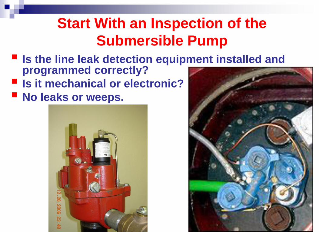
Start With an Inspection of the
Submersible Pump
Is the line leak detection equipment installed and programmed correctly?
Is it mechanical or electronic?
No leaks or weeps.
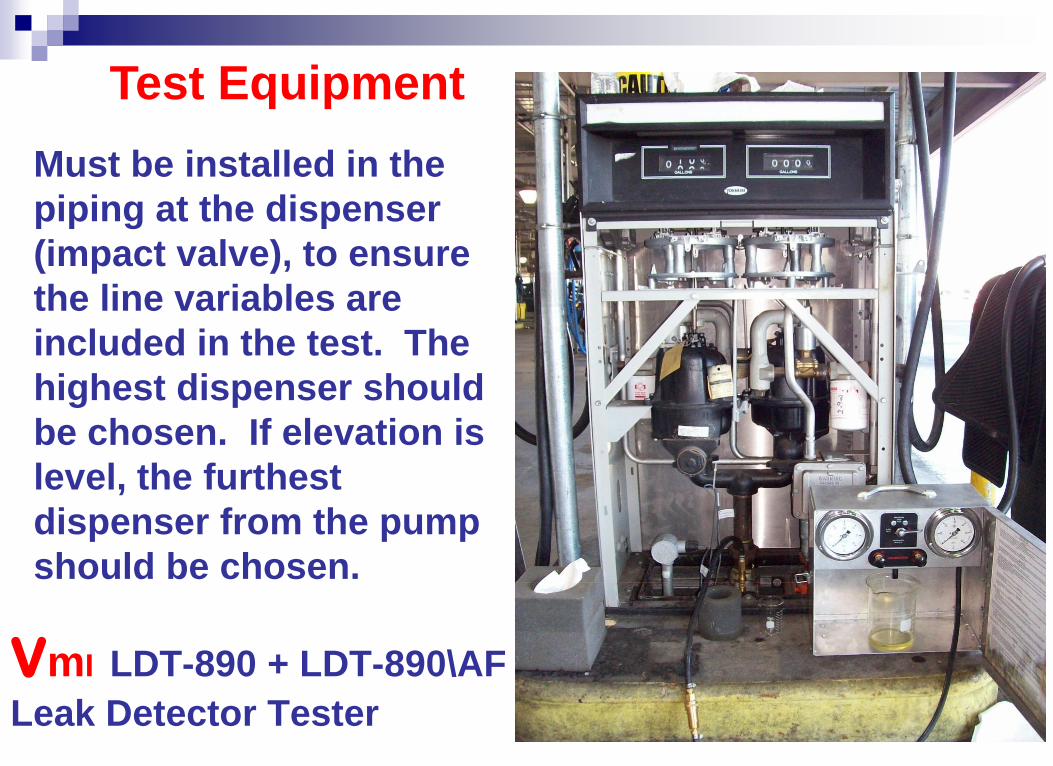
VmI LDT-890 + LDT-890\AF
Leak Detector Tester
Must be installed in the
piping at the dispenser
(impact valve), to ensure
the line variables are
included in the test. The
highest dispenser should
be chosen. If elevation is
level, the furthest
dispenser from the pump
should be chosen.
Test Equipment
Calibration of 3 gph @10 psi
If a Mechanical Leak Detector is Present:
Start with the submersible running.
Leak detector is open: line pressure
should be full submersible working
pressure (14~40 psi).

Full Pump Pressure
Calibration Verification
1. Turn 4 way valve to “Calibrate GPH.”
2. Adjust “Calibrate Pressure.”
The line pressure is reduced to 10 psi to confirm
an orifice of 3 gph @ 10 psi leak (Left side Gauge).
3. Measure In A Calibrated Beaker.
95 milliliters in 30 seconds
189 milliliters in 60 seconds

Calibrate leak rate @ 10 psi

Measure in a Calibrated Beaker @ 10 psi
to Insure Leak Rate Compensates for:
Pump Pressure
Viscosity changes in fuels due to:
Temperature differences
Fuel stock differences
Fuel grade differences
Fuel type differences – Bio vs. non-Bio fuels
Accuracy of Fuel Flow Orifice

Increase or Decrease Flow
to Meet 3 gph @ 10 psi
1. First Adjust Orifice Knob - more or less fuel.
2. Then Adjust Pressure Knob back to 10 psi.
Begin Mechanical Line Leak Detector Test
1. Bleed line pressure to 0.
2. Turn 4 way valve to “G.P.H Test” on
LDT-890 opens calibrated leak.
3. Turn on submersible.
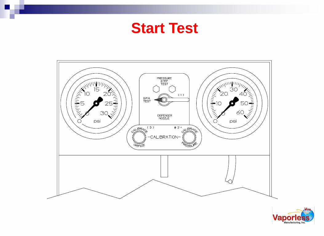
Start Test


Watch Pressure Gauge
(Right Side Gauge)
A leak detector goes through 3 positions.
1. 0 PSI - Reset for Leak Search.
2. 8 – 25 PSI - Leak Search/Tripped.
3. 14 – 40 PSI - Full Flow (pump pressure).
Leak Detector should stay in the
“leak search range.”
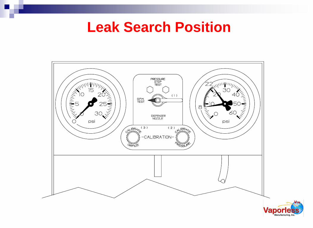
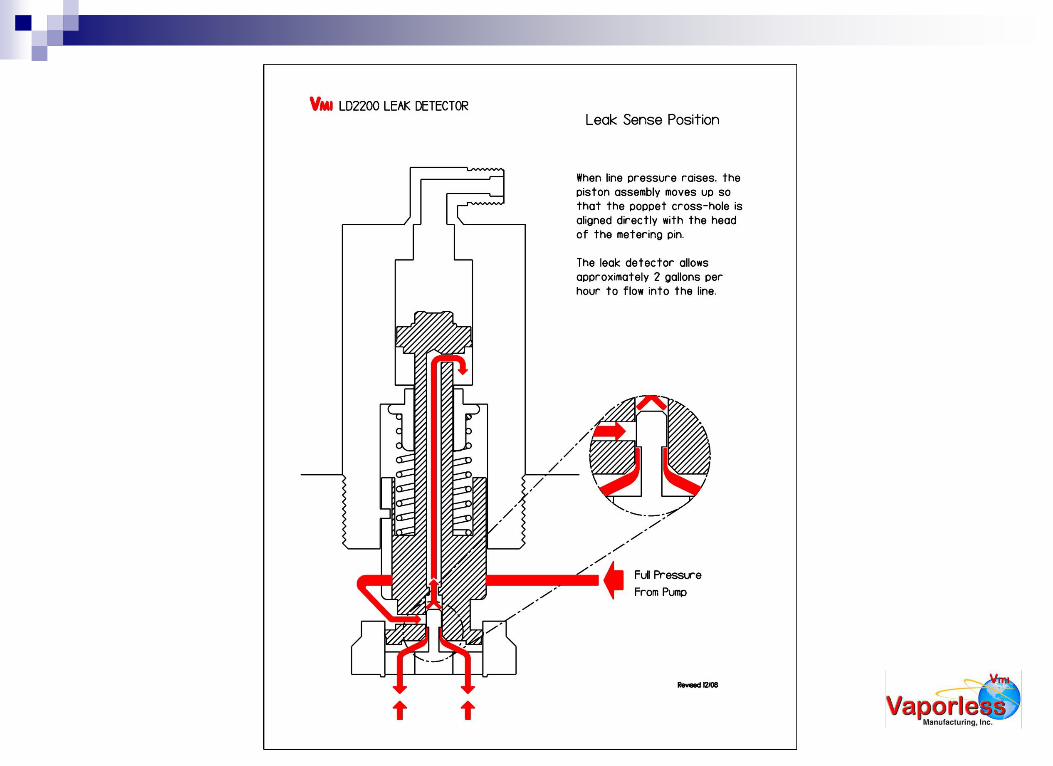
Leak Search Position

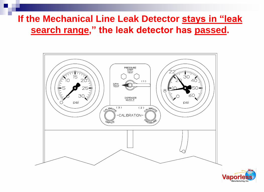
If the Mechanical Line Leak Detector stays in “leak
search range,” the leak detector has passed.

If the Mechanical Line Leak Detector does not stay in
“leak search,” the leak detector has failed.
How many positions do mechanical
line leak detectors go through?

A Leak Detector Goes Through 3 Positions.
0 PSI - Reset for Leak Search
8 – 25 PSI - Leak Search/Tripped.
14 – 40 PSI - Full Flow (pump pressure).


Leak Introduced, Pump Off

Leak Introduced, Pump On,
MLLD In Leak Search Range.

Leak Introduced, Pump On,
Failed Leak Test
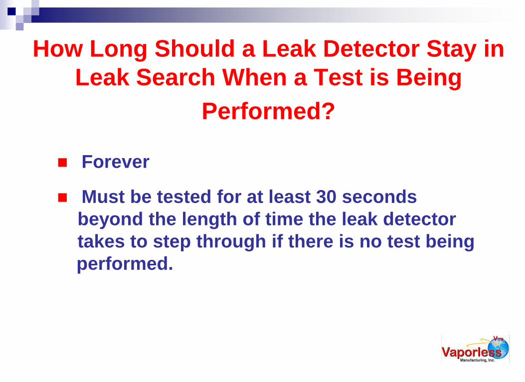
How Long Should a Leak Detector Stay in
Leak Search When a Test is Being
Performed?
Forever
Must be tested for at least 30 seconds
beyond the length of time the leak detector
takes to step through if there is no test being
performed.
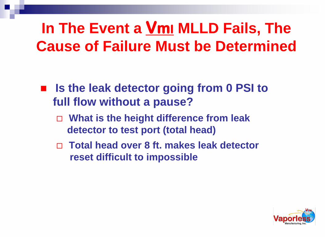
In The Event a VmI MLLD Fails, The
Cause of Failure Must be Determined
Is the leak detector going from 0 PSI to
full flow without a pause?
What is the height difference from leak
detector to test port (total head)
Total head over 8 ft. makes leak detector
reset difficult to impossible

(2) In The Event a VmI MLLD Fails
Is the leak detector pausing at leak search,
then stepping through? What is the Bleed-back (line resiliency
measurement)? High Bleed-back (anything
over 250 ml. for 2” MLLDs, 350 ml. for 3”
MLLDs) may cause a MLLD to be “bumped”
out of leak sense mode.
Try adjustment VmI leak detectors first
VmI has a leak detector certified for this type of
problem, the LD-2000\E and LD-3000\E
High Bleed-back also causes ELLDs to lose
sensitivity

(3) In The Event A VmI MLLD Fails
Adjustment of VmI MLLDs
The VmI Leak Detector may be adjusted to slow
down the flow into the line. This reduces the
hydraulic hammer that opens the leak detector
in high bleed-back lines.
Retest after each adjustment to the MLLD.
If the MLLD will not adjust to meet 3 GPH @
10 PSI, contact the factory with test information
for consultation.
Adjustment instructions also on web site.
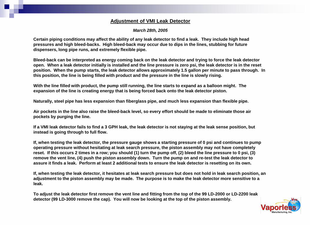
Adjustment of VMI Leak Detector
March 28th, 2005
Certain piping conditions may affect the ability of any leak detector to find a leak. They include high head
pressures and high bleed-backs. High bleed-back may occur due to dips in the lines, stubbing for future
dispensers, long pipe runs, and extremely flexible pipe.
Bleed-back can be interpreted as energy coming back on the leak detector and trying to force the leak detector
open. When a leak detector initially is installed and the line pressure is zero psi, the leak detector is in the reset
position. When the pump starts, the leak detector allows approximately 1.5 gallon per minute to pass through. In
this position, the line is being filled with product and the pressure in the line is slowly rising.
With the line filled with product, the pump still running, the line starts to expand as a balloon might. The
expansion of the line is creating energy that is being forced back onto the leak detector piston.
Naturally, steel pipe has less expansion than fiberglass pipe, and much less expansion than flexible pipe.
Air pockets in the line also raise the bleed-back level, so every effort should be made to eliminate those air
pockets by purging the line.
If a VMI leak detector fails to find a 3 GPH leak, the leak detector is not staying at the leak sense position, but
instead is going through to full flow.
If, when testing the leak detector, the pressure gauge shows a starting pressure of 0 psi and continues to pump
operating pressure without hesitating at leak search pressure, the piston assembly may not have completely
reset. If this occurs 2 times in a row; you should (1) turn the pump off, (2) bleed the line pressure to 0 psi, (3)
remove the vent line, (4) push the piston assembly down. Turn the pump on and re-test the leak detector to
assure it finds a leak. Perform at least 2 additional tests to ensure the leak detector is resetting on its own.
If, when testing the leak detector, it hesitates at leak search pressure but does not hold in leak search position, an
adjustment to the piston assembly may be made. The purpose is to make the leak detector more sensitive to a
leak.
To adjust the leak detector first remove the vent line and fitting from the top of the 99 LD-2000 or LD-2200 leak
detector (99 LD-3000 remove the cap). You will now be looking at the top of the piston assembly.
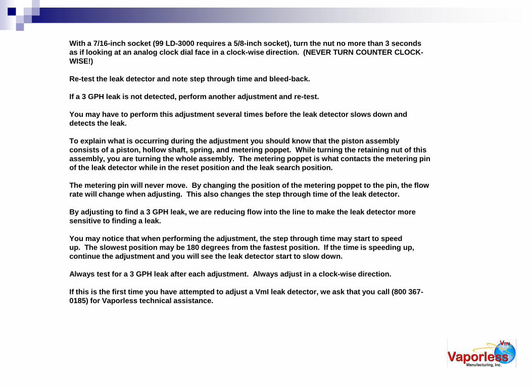
With a 7/16-inch socket (99 LD-3000 requires a 5/8-inch socket), turn the nut no more than 3 seconds
as if looking at an analog clock dial face in a clock-wise direction. (NEVER TURN COUNTER CLOCK-
WISE!)
Re-test the leak detector and note step through time and bleed-back.
If a 3 GPH leak is not detected, perform another adjustment and re-test.
You may have to perform this adjustment several times before the leak detector slows down and
detects the leak.
To explain what is occurring during the adjustment you should know that the piston assembly
consists of a piston, hollow shaft, spring, and metering poppet. While turning the retaining nut of this
assembly, you are turning the whole assembly. The metering poppet is what contacts the metering pin
of the leak detector while in the reset position and the leak search position.
The metering pin will never move. By changing the position of the metering poppet to the pin, the flow
rate will change when adjusting. This also changes the step through time of the leak detector.
By adjusting to find a 3 GPH leak, we are reducing flow into the line to make the leak detector more
sensitive to finding a leak.
You may notice that when performing the adjustment, the step through time may start to speed
up. The slowest position may be 180 degrees from the fastest position. If the time is speeding up,
continue the adjustment and you will see the leak detector start to slow down.
Always test for a 3 GPH leak after each adjustment. Always adjust in a clock-wise direction.
If this is the first time you have attempted to adjust a VmI leak detector, we ask that you call (800 367-
0185) for Vaporless technical assistance.

Common Causes of MLLD
Failure to Detect a Leak
Deep Burial
High Bleed-back
Several causes including:
Length of line
Type of line
Number of Flex connectors
Line with high spots
Line stub
Excessive Pump Pressure
Extreme Thermal Expansion
Defective MLLD

Electronic Line Leak Test
Calibrate a 3 gph @ 10 psi leak as
previously described, at the dispenser.
Turn 4 way valve to “G.P.H Test.”
LDT-890(\AF) - Opens calibrated leak.
With the calibrated leak in the line
(submersible still running) and leak
“open,” turn off the dispenser authorization
(hang up nozzle).

Start of Electronic Line Test

Electronic Line Test
Electronic line leak detection system
should detect leak, issue the appropriate
alarm and/or shut off the submersible.
Time will vary by manufacturer and pipe
system.
Authorization of any dispenser during an
electronic line test will abort the test.

Questioning Equipment Function
and/or Testing
When equipment functions different from
expectations is it rejected? Call Factory.
Is the equipment meeting criteria: 3rd party
certification, 3rd party description, manufacturer’s
explanation, other manufacturer’s concerns,
additional reports.
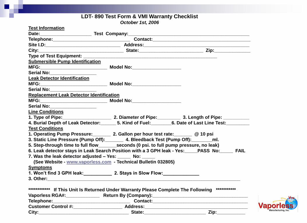
LDT- 890 Test Form & VMI Warranty Checklist October 1st, 2006
Test Information
Date:____________________ Test Company:_______________________________________________
Telephone:______________________________ Contact:______________________________________
Site I.D:_____________________________ Address:_________________________________________
City:_________________________________ State:_________________________ Zip:______________
Type of Test Equipment: ____________________________________________________
Submersible Pump Identification
MFG:__________________________ Model No:___________________
Serial No:__________________
Leak Detector Identification
MFG:__________________________ Model No:___________________
Serial No:__________________
Replacement Leak Detector Identification
MFG:__________________________ Model No:___________________
Serial No:__________________
Line Conditions
1. Type of Pipe:___________________ 2. Diameter of Pipe:_________ 3. Length of Pipe: __________
4. Burial Depth of Leak Detector:______ 5. Kind of Fuel:________6. Date of Last Line Test:_________
Test Conditions
1. Operating Pump Pressure:_______ 2. Gallon per hour test rate:_______ @ 10 psi
3. Static Line Pressure (Pump Off):_______ 4. Bleedback Test (Pump Off):________ml.
5. Step-through time to full flow_______seconds (0 psi. to full pump pressure, no leak)
6. Leak detector stays in Leak Search Position with a 3 GPH leak - Yes:_____PASS No:_____ FAIL
7. Was the leak detector adjusted – Yes: _____ No: _____
(See Website - www.vaporless.com - Technical Bulletin 032805)
Symptoms
1. Won’t find 3 GPH leak:___________ 2. Stays in Slow Flow:______________
3. Other:___________________________________________________________________________
************ If This Unit Is Returned Under Warranty Please Complete The Following ***********
Vaporless RGA#:_____________ Return By (Company):_____________________________________
Telephone:______________________________ Contact:_____________________________________
Customer Control #:___________________ Address:________________________________________
City:___________________________________ State:________________________ Zip:___________
Review VmI literature online:
www.vaporless.com
Leak Detector Installation
Catastrophic Line Leak Detection
Testing Using the LDT-890(\AF)
Equipment Specifications
Online Certification Testing for
installers and testers
More!