Catapillar 20 Test 150
45
University of Nebraska - Lincoln University of Nebraska - Lincoln DigitalCommons@University of Nebraska - Lincoln DigitalCommons@University of Nebraska - Lincoln Tractor Maintenance Repair and Restoration Tractor Test and Power Museum, The Lester F. Larsen January 1928 Catapillar 20 Test 150 Catapillar 20 Test 150 Tractor Museum University of Nebraska-Lincoln, [email protected] Follow this and additional works at: https://digitalcommons.unl.edu/tractorpower Part of the Applied Mechanics Commons Museum, Tractor, "Catapillar 20 Test 150" (1928). Tractor Maintenance Repair and Restoration. 4. https://digitalcommons.unl.edu/tractorpower/4 This Article is brought to you for free and open access by the Tractor Test and Power Museum, The Lester F. Larsen at DigitalCommons@University of Nebraska - Lincoln. It has been accepted for inclusion in Tractor Maintenance Repair and Restoration by an authorized administrator of DigitalCommons@University of Nebraska - Lincoln.
Transcript of Catapillar 20 Test 150
University of Nebraska - Lincoln University of Nebraska - Lincoln
DigitalCommons@University of Nebraska - Lincoln DigitalCommons@University of Nebraska - Lincoln
Tractor Maintenance Repair and Restoration Tractor Test and Power Museum, The Lester F. Larsen
January 1928
Catapillar 20 Test 150 Catapillar 20 Test 150
Tractor Museum University of Nebraska-Lincoln, [email protected]
Follow this and additional works at: https://digitalcommons.unl.edu/tractorpower
Part of the Applied Mechanics Commons
Museum, Tractor, "Catapillar 20 Test 150" (1928). Tractor Maintenance Repair and Restoration. 4. https://digitalcommons.unl.edu/tractorpower/4
This Article is brought to you for free and open access by the Tractor Test and Power Museum, The Lester F. Larsen at DigitalCommons@University of Nebraska - Lincoln. It has been accepted for inclusion in Tractor Maintenance Repair and Restoration by an authorized administrator of DigitalCommons@University of Nebraska - Lincoln.

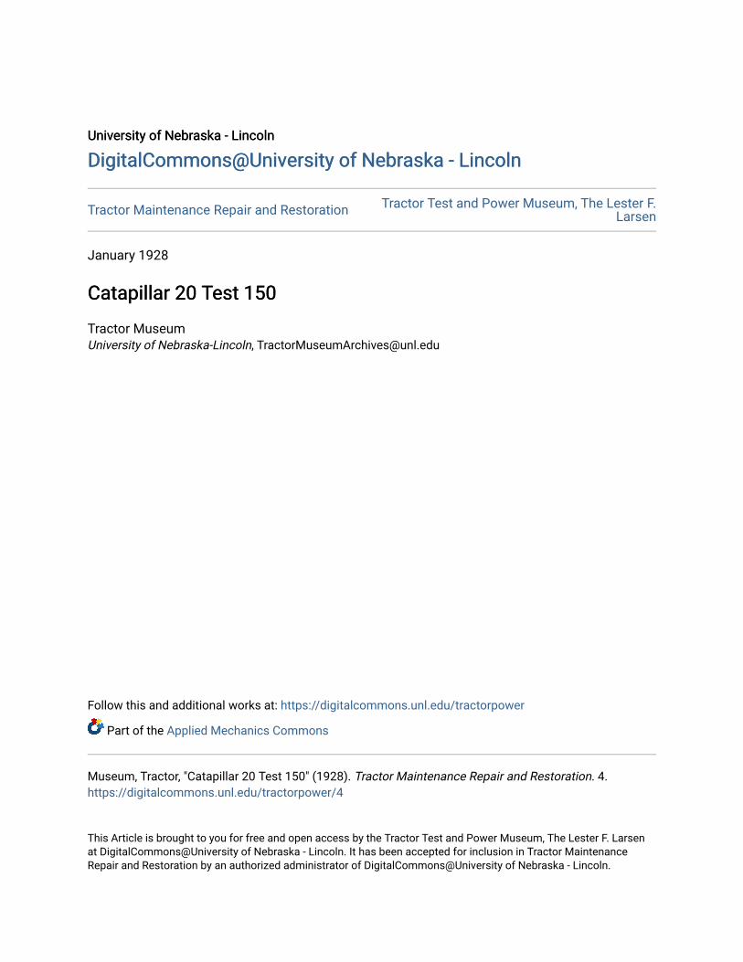
T ABORATORvand fieldL tests, exceeding inseveri ty t he most ex'tr eme actual serviceand equalling in durati on many months ofnormal u sc, precedethe public appearanceof an y "Caterpilla r"mod el. ...... T ra ct orswallow m deep mud;leap from runways topunis h s pr i n gs; airclea ners are ope ratedin clouds of powderfine dust; engines arcsu bjec te d to extremeover -loads ; comple tetractors arc built anddiscarded. Every new"Caterpillar" model istime-tried and proven .

"CA T ER P I L L AI/ "
WIT H the issuance of this catalog, a new size of the"Caterpillar" Tractor takes its place in the "Caterpillar" family. The T wenty is a new tractor- new
in size, new in rating, new in price, new in that it embodiesthe latest accumulation of the many years of "Caterpillar"expen ence.
In a broader sense, the Twenty is not new-the knowledgebehind it is that of the pioneers of trac k-type tractor designand construction- technical kn owled ge enriched by thepractical experience of thousands of "C ate rpilla r" usersth roughout the world.
In the same broad sense, every model of the "Caterpillar"is always new . Each passing year finds the builders of the ,"Caterpillar" T ractor better armed to build better t racto rs.Refinements, changes of greater or less consequence are can'tinua lly being made in all sizes of the "Caterpillar." If thesechanges were held in reserve it would be possible to announce "new models" of all the present "Caterpillar" sizesevery two or three years. Bur the effort of the CaterpillarTracto r Co. to constantly better its products is a continuousone, and the fruits of that effort are promptly passed on topurchasers. Thus there is opportunity to present a really"new model"only when a "new size" is produced to broadenthe "Caterpillar" line.
The Twenty enters the "Caterpillar" family, joining itsbrothers in doing the world 's work Better,!!I.ll ic~er . Cheaper.
[ P<l'gd ]

[ Pag(6 ]

"CA TER P I L LA R '
Purchase of a "Caterpillar" T ractor is investment in theability to do Better, Quicker, Cheaper work . The "Caterpillar" is powerful-and sure-gripping tracks make its poweravailable when and where it is needed. The "Caterpillar" isdependable- and its amazing endurance assures a long lifeof dependable service. The "Caterpillar" is economical- itsoperating and upkeep costs are low-its records of accomplishment, low cost per ho rsepower hour, are unsurpassed.
T hese things mean much-- when fields demand immediate plowing or planting;- when a road contract must be completed on time;- when logs are ready to be moved;- when a big yardage of earth must be transported
quickly;- when industry demands lessened hau ling costs;- when there are heavy loads of any kind to haul through
mud, sand or dust- up hill and down-over all kindsof roads or no roads at all.
Such performance is made possible by many unusual features of design, materials and construction, briefly describedin the following pages.
For convenience, the T wenty is discussed under three gen~
eraldivisions: The Engine, or power-creating unit;the Transmission, or power-conveying unit; and the T rack A ssembly,or the unit which transforms power into accomplishment.
Because of the special interest attached to the traction principle employed in the "Caterpillar" Tractor, this feature ofthe Twenty is described first.

"CA T E R P I L L A /I"
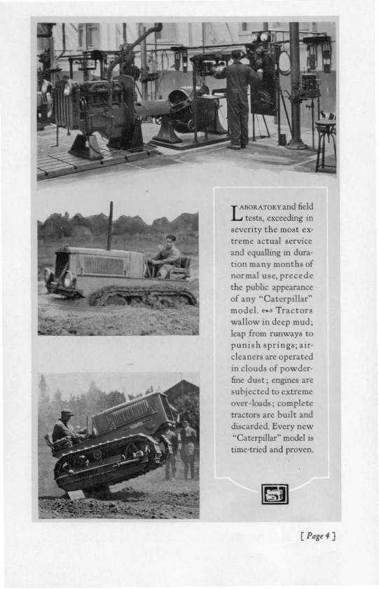
Track AssemblyTrack Roller Th e track roller frames are of the single unit,Frames oscillating type, made of heavy structural steel.They are fastened together by alloy steel bolts, making iteasy for operators in the field to do repairing, should accidental damage occur. The frames are notable for their sirnplicity of design and are properly braced and held to correctalignment. A heavy angle brace connects each roller framewith the center of the sprocket shaft. It is practically impossible to damage the frames, except by th e greatest abuse.
Both outer andcenterbearings at the rear of the track rollerframe are very heavy castings, with large bearings on theaxles. They are bored to an accurate fit. The center bearingsare grooved inside to retain the grease. All are lubricatedthrough standard Alemite connections.Spring An equalizer spring carries the weight of the frontEqualizer end of the tractor to the from part of the rollerframes. It is a heavy, alloy steel. laminated spring that absorbs
On, 01 1M T,«* Rolin Fr"mt•• ,110.,;,., ,}" t'M.!: ul,,,'r Ip"n,. ".....1: urnn ,o/In""..d ,n. """ ,ht "", It b.act 10 1M ,,"« len '''''ft.
[ Pagt' 9 ]

"CA TER P I L L A R "
the shocks and jars of rough travel and allows full oscillationof the track frame. The spring is held within correct oscillation limits by a supplementary leaf spring.
Idlers and The front idlers arc one-piece, special-analysisTrack Release steel castings, provided with spiral roller bearings and adequate dirt seals. They are mounted in slidingboxes wh ich are positioned by alloy steel hel ical springs.
These springs are designed to maintain the idler in its normal position under all working conditions, but in the eventthat the track becomes clogged, the springs recoil, therebyallowing the idler to slide back and prevent undue stra inupon the track roller frame and the track until the foreignmaterial becom es dislodged. T his feature provides a safetytrack release to prevent b reakage whic h might otherwiseoccur.
The front idlers are easily adjustable to take up any slackor sag in the tracks.
Track Rollers The track rollers are o f composite assembly,each roller consisting of a heavy grey iron hub with forged

"CA TER P I L LA R "
A .«,i"....! ...it.. of " ntolt~T'MtC.."in
Rolin " 0 of ,htu.olln., on h tid..
of ,h.. / ,<>et"••'"PI'''''''I~ ..!'~ ,;J.. of Ih..,,«,t N ot..",,* :J...
I><,,"III ....J "' '' ,d,,,,,,h .u",rly lochJ... "I«t, IP....""I,
,(""" ..M...
{ Pdgt II J

"CA TER P I L L A R "
steel rim shrunk all . The roller assemblies run on large spiralroller bearings which are provided with adequate oil and dirtseals.
Track Carrier A track carrier roller is mounted in a bracketRoller on each side of the tractor. This roller SUP'ports the top of th e track and keeps it in line.
Track Assembly Sheet -steel guards cover and p ro tect allGuards parts of th e track roller frame assembl yfrom mud, dust and sand.
Track The Twenty track is of the buil t-up type, consistingof drop-forged steel shoes, bolted to drop-forged, heat-treatedsteel links by alloy steel bo lts. The links are machined and areheat treated for maximum wear and strength; the links areassembled, in tum, with machined, carburized and hardened
The ill" '" . ide of ,he T,tlr~ AHr",bI,-NoU Ih<ll tht in"., '" . A Itlf the ouln Jid e i. th"raUK"' ] ,hit/J.d.
[ Page12 ]
•

"CA TER P I ll A R "
steel track pin bushings, whi ch arc forced into place underheavy pressure.
T hrough th e link 00s."" are forced the carburized and hard ened steel pins, Bushings and pins are made with close fi tsand counterbored ends to prevent dust and dirt from enter'ing and causing wear of the bearing surfaces.
To th e links are bolted the track shoes. These shoes aresteel drop forging&-th e bolts that hold th em to the links areof alloy steel, heat treated.
T he great durabi lity of th e "Caterpi llar" tracks is duelargely to scient ific heat treating of metals. For example,the links are each heat treated to give them the maximumst rength and shock resistance, the rail surface of the link receiving further special heat treatment to give it maximumwear resistance. Each part of the track receives the specialheat treatment necessary to give it the desired qualities. T heresults of this construction, together wit h scientific design,are remarkably long life and low upkeep.
T mk Shoe, The standard t rack shoes of the Twenty areeleven inches wide. T he standard shoe is the right design togive best service and best results under a wide range of conditions. Other special shoes, grousers and plates are providedon special order.
Th e Twenty EngineT he T wenty power plant is of the four-cylinder, four-cycle,
water-cooled, valve-in-head type, and is designed in everydetail to withstand the most rigorous demands of tractorseIVICC.

· CA TER P IL L A R"
Such service differs materially from that required of otherautomotive equipment. An automobile, for example, exertsits full power only when traveling at top speed or climbingsteep grades, most of the time using only part of the powerand operating under ideal road conditions.
The tractor, on the other hand, must handle a full loadpractically all the time, and frequently under th e most diffi cult conditions. T he "Caterpillar" engine is suited to suchhard work.
Co-ordination The engine is all-tCaterpillar" construction,with every detail carefully designed to co-ordinate properlywith all other units in the assembly,
[ Pagt H]

"CA T ER P I L LA R"
Speed The normal full load, governed speed of the engineis 1100 R.P.M. The cylinder bore is fou r inches and thepiston stroke is five and a half inches.
Crank Case The crank case is a one-piece, barrel-type greyiron casting, with heavy oil sump cast integra l. Unusual accessibility is an important feature. Large doors at the sidesgive easy access to the interior foradjustment or replacementof any of the main or connecting rod beatings, as well as thepiston pins and pistons.
The crank case is bolted rigidly to the fron t end of the
[ Pdg~ J .s]

' CA T ER P I L L A R"
I&lf - -
transmission case, the two units forming the main frame, asturdy backbone for the entire machine.
Crank Shaft The crank shaft, 2Y2 inches in diameter, is anunusually heavy drop forging, heat treated, so designed asto avoid any vibration period within the engine's operatingrange. A flange is forged integra l with the shaft; to th is flangethe flywheel is bolted. Large oil passages are drilled from allmain bearings to the crank pins.
The three large main beari ngs are so designed that th e loadon all bearings is uniform and also that proper alignment ismaintained over a long period of service. The bearings aremade in two parts; each bearing is composed of a babbitt -
T"~ C,_A: C"J~" 1tIJ.,J, ..", It , ...,i",. T~ 141ge ..Je O~II" ......1: .I~ r1&li" ;lUmor r. JiJ, Mu."bl, .
[ Pag. l6 ]

" CA TER Pi ll A R "
T~ C.....*51>,,/, !tf..i" Br"';", •. A/In ,...l:i"c off 11,( c"'p , 1M I" fh~1 Col" be,oItllrd "" 1M .&.// "nJ .r"l""rd . ,;,/00"1 J.. ......nJI/;./i,,1l 1M ,;"t.
[ P' C<17 )

"CA TER P IL L A R "
-lined steel shell and a dro p-forged steel cap, also babbittlined. Laminated babbitt-Faced shims are provided for bearing adjustment,
At the rear end of the crank shaft is an oil thrower toprevent leakage under all working conditions. Crank shaftthrust is taken up by a special adjustable thrust bearing atthe front end of the shaft.
The entire construction is so designed as to insure long lifeand freedom from trouble.
T~ Pi,to" -J C...."«ti,,s Rod A ..~...bi,. ~nJ. i" l~ b«ft""" ,.J. /• • o/ llwcy/i,t<h". N~~ ill p.ntKoJ.n , lot "''''''' ''If.. pi.., pi""" ptl, .
[ Pag~18 ]
•

"CA T E R P I L L A R "
Pressure T he crank shaft and crank pin bearings, valveLubrication rocker arm shafts and fan shaft are lubricatedby pressure oil system.
Connecting Connecting rods are of l-beam cross-section,Ro,h high-carbon, drop-forged steel, heat treated. Thebig-end bearing is anti-friction babbitt , cast directly into rodand cap. The small end is bushed with hard bronze bearingmaterial. Both are lined up in a special aligning fixture beforeassembly, T he connecting rods are strong, yet all unnecessary weight is eliminated. to avoid undue centrifugal forceand prevent crank shaft VIbration.
Pistons Pistons are grey iron castings. T hey have very longskirts, four compression rings and one oil ring. T he pistonpins float freely in both the piston and the connecting rod,and are retained by aluminum, die-cast plugs, pressed in the
[ Pagt 19]

"CATERPI L L A R -
l;--f-----1ct-------
piston. These plugs prevent the ends of the pins from scoring the wallsof the cylinder.
Cylinders Cylinders are cast singly, of a special grey ironmixture, and are provided with ample water jackets. Cylinder bores are machined to very close limits and honed to asmooth finish. Should one cylinder be accidentally scored orotherwise damaged, it can be replaced without the expenseand delay of replacing the entire assembly.
Cylinder Cylinder heads are also of special grey iron, castHead, en bloc, and provided with the most approved arrangement o f water-cooling areas.
A dustproof, pressed-steel cover encloses the cylinder headand protects the rocker arm mechanism from dirt as well asforming an oi l-t ight co mpa rtment, The valve-in -head
Tilt T..ntl y [ 1ll int .nIh t:yt;"Jn 1n..J C<lWT um"uJ. Tht (""....mOIl < /0,.u/i"to. 4ft "II "",,,1--"0 , ,,bb... h",t .

"CA T ER PI L LA R"
T"~ TimillXG~"", .
I(}cdl~ "'lh~ 1""'1mtl of IJ,~ ""gi,,..,"'r d ,op IO'/fed',om mK" ,."bo""ul. T~ ,r""&n..rid.. j ..crl.,.J &..,., pitch/«th. T & ~.,.b.Jl
t<>"'~il_..trJOft tM _,"'" ,<,<IT
.md sh./I, . hiehJri,n,h.. . dln p" mp.,.Jm",IIno. G...... a U
",<11hJ /0 j ..ri!i/4Jr(otTrtllimi"K·
const ruction and removable head make for ready accessibilityand facilitate the grinding of valves,

"CA re« P I L LAR "
A~"""I,,,,,, 1M "<nil n.J
0/,hI' T .nu,. E",i"l'.YJu rttfJI,,,idr,
_.I 'i/ln ,,,,.II"<PI' u ",.., ,,loJr.
Thr "Pi'" rnJ 0/11.1' p,,,h,oJit"
!>...Jnlrd ital ewp- , 1>1' b.,/f ,1>..,
ull. ill 1m. e"pi ,1Mfo.n r..J 0/
.... .JjM<t..blr~r.tit« ".mJu 1M",,,..uo' t• .I:.,,,..pl#lt~;"
1M ,.J~ m«,,-*.....
Timing Gears Timing gears are drop forged from high car'bon steel, and have wide faces with helical-cut, heavy-pitchteeth. Lubrication is by pressure from the main oil line.
Cam Shaft The cam shaft is a large diameter forging of heattreated steel, wit h earns and oil pump drive gear integral. allworking surfaces carburized and ground. T he shaft is provided with a special type of thrust bearing, of large capacityand positively lubricated. The line bearings for the shaft,

" CA T ER P Ill A R "
Thi.,ho. , ,, 1«'Hm01 ,~Cyl;rJrr H~..J ,
V"/u, -J V"'~~51"'" C.uJ~ I.
T IH ~J"~I ...t of.t/ay ./ni .",«lnnnl .."JM'"' mild . In/4ft• .."'''',.J'6n"0'" n h4.. ,/..J ..n in Jt';~ .. .. .ui(om/'O,;t,on-t« hP/uJ jor ill pa./ic"/6T'rr ";u.
machined directly in the crank case, are unusually long. Theyare lubricated by throw-off from the crank shaft. T he camsare " ide, and so designed that the valves are held open forthe correct period of time, and close gradually and easily,even when the operator fails to maintain accurate lifter adjustment.
Valve The cams operate the valves through lifters,Mechanism push rods and rocker arms. A t the top of eachpush rod is a hardened steel cup which carries oil. In thiscup, immersed in oil, rests the ball end of an adjustablesere;in the end of the rocker arm.
The rocker arms are so designed that maximum valve liftis obtained with minimum cam lift.
The intake and exhaust valves are of special alloys of steel,and are machined and heat treated. A ll valves are fitted inremovable stem bushings, which may be replaced when wear
( P~gt ZJ ]

TH E ileAT ERPI LI
~R" TWENTY

,.is
[ Pagt 16 ]

"CA TER P I L L A R "
finally occurs. The valve heads may thus be kept in correctalignment with the seats.Governor T he governor is of the centrifugal, fly-ball type,enclosed at the front end of the engine in the timing gearcompartment, and is so designed that it will control the engineat all speeds with close regulation. It is built as a unit withthe water pump assembly and is lubricated by splash fromthe timing gears.
The engine speed is regulated by a hand throttle which actsdirectly on the governor spring in a manner that providesgovernor control at either high or low engine speeds.
Breather T he breather is in effect a miniature air cleaner.containing Oil-saturated fibre to catch dust that would otherwise enter the engine.
Air Cleaner From the foregoing descriptions it will be notedthat every precaution is taken to enclose and protect allworking parts of the tractor. "Caterpillar" engineers wereamong the "pioneers" in recognizing dust as a serious drawback to long life and efficient performance, and among thefirst to perfect means of protection, bot h from direct contactand from dust drawn with the air through the carburetionsystem.
T he air cleaner is of the co mbination centrifugal and oiltype, centrifugal action removing the heavier particles andoil-saturated curled wire "hair" collecting the finer dust. Thiscleaner has amazing efficiency- the value of such completeprotection is apparent when it is considered that most tractors must operate in dust a large part of the time.
O il Pump T he oil pump, driven by spiral gears from the camshaft, is of the duplex type. The pressure unit delivers oil
[ Pagt 27]

"CA TER P I ll A R"
under pressure to the fi lter for cleansing, the clean oil thenbeing distributed to the crank shaft and connecting rod bear'ings, the valve gear, timing gears and fan shaft bearings. T hescavenge pump is provided to prevent 011 from collecting inthe front part of the engine. The pump has ample capacityfor delivering lubrication through separate tubes, at lowestspeed; surplus oil, at higher speeds, being returned automatically to the sump. T he sump is so located that the rear of thecrank case does not fi ll up on steep hills.Oil Filter A case fitted to the right rear door of the crankcase contains the oil fi lter, designed w it h two elements tothoroughly clarify the oil. Filters may be renewed or reremoved without breaking the o il line . Entrance is madethrough a cover in the top of the case.Air Heater The air heater is located in the inlet manifoldandcontrols the temperature of the mixt ure passing into the en'gine. T he valve is operated from the driver's seat. T his fearure greatly facilitates "warming up" in cold weather and increases fuel efficiency.Fuel Fuel is supplied from a heavy-gauge, sheet-steel tank,double-seamed at the joints, and located directly behind theengine,providing gravity feed to the carburetor. T he capacityof the tank is 22gallons. Fuel is filtered by a standard strainer.Gasoline is the recomm ended fuel, but provision is made foroperation by kerosene when required. Alcohol may be employed as fuel by the use of a special carburetor. T he heatcontrol system is adequate to handle any standard fuel.Carburetor T he carburetor is of the plain rube type. so de'signed that it will operate on all grades encountered in service. The carburetor is of special design to meet the rugged
[ P,.d'J

"CA TER P I L L A R ",
requirements of tractor service and, in particular, to exactlymeet the requirements of the T wenty engine. T he carburetorhas an automatic eco nomizing device to insure greatest pos'sible fuel economy and engine efficiency. The throttle shaftand bearings are of hardened steel,sealedagainst the entranceof dirt at the bearings.
ljitnition The standard electric system consists of a high tension magneto, equipped with an automatic impulse startingcoupling. The magneto is in a readily accessible position onthe water pump shaft, by which it is driven.
The entire ignition system is carefully protected againstdust and the elemen ts.
"CAT ERPI LLARS "GRIN ATTHE GRIT
- they don't complain about dust, silt andsand. "Caterp illar" engineers have won theirlong duel with the Dust Demon - effectiveseals, thorou gh air cleane rs, scientifi callyheat-treated metal parts, close fits-c-all th esehave contributed to a splendid victory thatmakes "Caterpillars" long of life and notablefor low maintenance cost.
[P'g'" J

' CA TERP I LL A II "
3
Tbi, .1,0"" u~~t,,1
uf ,he "",,/ imporl"'"jlmlf in the cooling.y,lrm-th, ,..didI01,/ .", and f<ln l /" "kti,and Ih rr ", off'"hOUJi"g. TheIh..mo.'al i, in ,h,1'1'1'" (Orm...:t;""b,t.,un ,,,dialo' "ndmginr. The fa" d.j~r
indud",,, rib, ,,ti,,nJ"",pmrr 11,01ai",ablo.b . th, ihodt.lof ,taTting and' Ioppinl/. .
Cooling The cooling system consists of radiator, fan, therSystem mostat , water jackets and connecting piping. Thesystem is designed to keep t he engine temperature lowenough to avoid boiling, yet high enough to insure maximum fuel economy.
The radiator has cast iron upper and lower tanks and sideplates and is of the vertical, flat tube, st raight fin type, rigidlyattached to the motor head at the top and to the crank caseat the bottom. 'There is no rubber hose in the assembly.
[ Pdgr 30 ]

"CA T ER PI L L A R"
.Fan T he fan is specially designed. 20 inches in diameter,with six wide, high-carbon sreel blades, mounted on a heavyspider. Incorporated in the fan drive is aspecial type of vibration dampener which prot ects both fan and gears againstshock loads.
T he fan shaft runs in three bronze-back. babbitt-lined bearings, which are provided with pressure oiling from the engine's lubricating system.
T he fan is driven by helical spur steel gears, all entirelyenclosed and positively lubricated. This construction eliminates the expense of fan belts and the overheating resultingfrom the uncertainty of their operation.W'ater Pump The water is circulated by a gear-driven centrifugal pump , designed for very rapid circulation. It is provided with a rust-proof alloy steel shaft and accessible stu ffing boxes. t\ graphite-packed bearing for the pump shafteliminates need of lubrication. The entire water pump assern-

' CA TER P I Ll A R "
•
T hi. picl~ tr show'thc" pm ""Jc/o' cdpori/i'm' of thc,/'n", oll <l1 I"/ .,,t .Con lrol "I ",,,t..,circ" lat;"n <lid, t heoblon";"Koj high..!cfJicim cy in rnginc"fUr" t"",.
bly forms an independent unit with the governor, thus insuring perfect alignment of these parts. The pump is not onlyunusually efficient, but also easily accessible. W hen the radiator is drained, all water automatically leaves the pump body,thereby eliminating the possibility of damage by freezingan important safeguard in winter operation.
W ater Jacket T he engine has a specially designed water jacketsystem with passages properly narrowed at the hottest pointsto keep the water circulating past those points at highest velocity. The valve seats are completely encircled by water.Provision has been made to give equal protection at all vita lparts in the engine.
Thermostat The engine has a specially designed water jacketcontrolled valve which maintains the water in the jackets ata minimum temperature of 160 degrees Fahrenheit. This insures low fuel consumption, rapid warming up and minimumcrank case dilution. The thermostat control greatly facilitatesthe combustion of low-grade fuels.•
[ P<Jg~ J2]

"CA T E R P I L L A R "
T ransm issionThe word "transmission ," as used herein, includes all parts
involved in transmitting power from the engine to the tracks.
In the transmission are included many features whichare chiefly responsible for the high efficiency in delivery ofpower. The principal reasons why the "Caterpillar" deliversso high a percentage of power to the drawbar are; elirnination of differential gearing, the use of only three gear reductions in any speed. and the employment of anti-friction bearings throughout.
[ P48~ 3J ]

"CA TER P I ll A R"
Transmission The transmission case is a heavy grey-iron castCase ing, strong and well reinforced by webs. Thesteering clutch housings are separate castings. that are boltedto the sides of th e t ransmission case proper. T he final dri vehousings are bolted to th e steering clutch housings.
Flywheel The flywh eel clutch is of th e single dry-plate rype,Clctch especially designed for long life and freedom fromoverheating .
A l«I;"rwI"~"of /he FlyW~JCI..teh Aur mbl, .ThO"~r--UHI", r iJu of,J.r,INcll;"ru II/1MclJdcb pJ"U~'M/"'''c"01,,,,,( ..1md.,}p.o.,jJr,I".,c , ..".,nt,for hCdt ab,,,rpri,,,,.Thi, ud;,,"../..,,h",,' lbe c""plinK'''4'lh", «i",<J.."b1r"",,,,,,J «Ii.... intMcO""....ticnr bn..urtd,de" ""J"...,,_...i.... .TIK 'P';"l-nt, ,,,,nJpi"M".. tM"",pl,,,,,,&.flllNh1J.rri"'clt..J;u."",,,,,.
[ Pagr J4 ]

"CA TER P I L L A R"
1;---
The driven member of the clutch is a heavy cast-iron plate,to both faces of which clutch facings are riveted. The drivenmember runs between the flywheel and another heavy castiron plate. The large volume of metal in the clutch platesgives big capacity for absorption of heat. T he clutch designalso provides a vigorous circulation of air to insure positivecooling. The clutch is mounted as a complete unit in the flywheel housing and is virtually a part of the engine assemhly.Adj ustment of the clutch is made in a very simple mannerby pulling one pin and turning the disc. Clutch release is positive, powerful springs being provided to prevent any draggmg.
The clutch drives the upper transmission shaft through themedium of a short , toot hed coupling shaft that forms an allmetal, double universal joint requir ing no lubrication. T he
I" ,bi' Ie'oMp a'~''''''-rl, al lh t lOp .Ih U ppn -" "'11'mitt ;".. 51>"1' ,,,,d
C_,,,",,,"·c,,,.pJ"'1C Sh4f'
lh.tl fO''''UII ,hi.,h..{t 10 l~ d"uh;;.. '~ «YfI".'~R~"uGt,p;.
I~ boll."" .I~ 10 .'"T,........;I/i".. 5"<,/1
and ICUrI. T ht b....dpi";,,n;, fO '/{ ffl
;nltg ,<1I Jl'i lh l1uI"wn ,""f,.
( Prlg t'J5 ]

"CA TER P I LL A R"
TMT,......";•...,,.C••~ErJ Pi",e. TIN. pi"'"Md by 1M 4".J. '"1M /'QI<l tttd 011Mtr ...... .,.;,....... c.~.
c"";n Ihr u ..rt...
If''-''~ -J hold. thr/ '''''' bto"";"jl' fm 1M"PI>" ."tI ttl...." .... 'mi,';oll ,1>../1..,1...,,, ..... 1"'11" lil<'ballbr""i"1/1. rs,"''''0',j" aJdi/ j,m 10
,},.. o, },n 01'<"'''''' i",1.('/, ..,um;, ";,,11 Ctllr ,
/li,tl """Ju"lIr ..o m·pltl .. «a"ibifi,y 10,h.. i",,,,;,,.,
clutch pilot bearing is of the spiral roller type and likewiserequires no lubrication.
Gears and T ransmission of power from the engine throughShaft> the clutch to the track is accomplished in threegear reductions - the fi rst in the change speed gear set, thesecond in the bevel gear drive, and the third in the spur gearfinal drive.
All gears in the speed change are cut from high carbon,alloy steel drop forgings and are heat treated for maximumwear resistance. The bevel gear is cut from a solid, hammerupset forging of alloy steel. A ll transmi ssion bearin gs areeither single row, ann ular hall bearings or tapered rollerbearings.
NCA T£ R P I LL A /l"
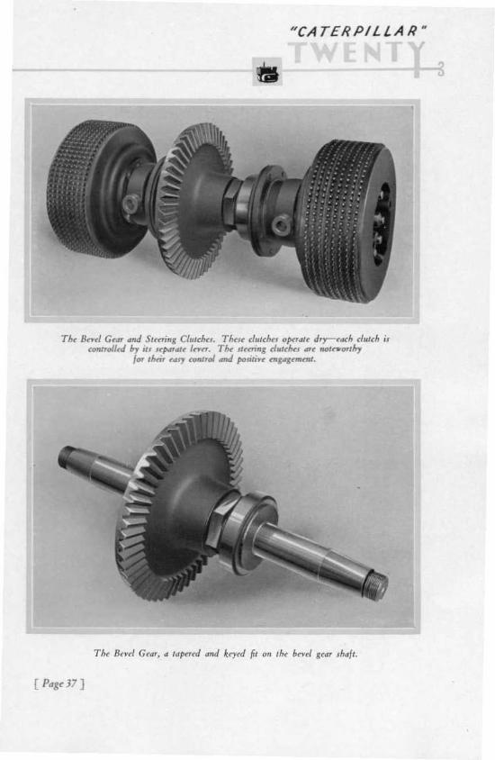
T&: Bnd G~.n "nJ Sumnll Cl"lchn Thnc f/"lchn DJwrdtt dry-told, cluteh ilt<nIl,olfrJ by j " Jr1"P"U In". The .,«ri.., d,"c&:1 .nC ,..,ua-o.,h,
I'" ,10m c~ ton/,ol ...J ,.,<iti"" ... , .., .....""'.

"CA TER P I L L A R"
The upper transmission shaft is cut from high carbon steel;the lower transmission shaft is a heat-treated upset forgingof alloy steel, forged integral with th e bevel pinion. Fromthe bevel gear, power is transmitted th rough a heat-treatedshaft, thence through the steering clutches to the final drivepnuons.
A 'fflio....l ........ 0' ,Jot BntJ GtOOT_o~.. of ,,,.. "tmn1!. ~1.~t~l. p",J Jri ~t pu,;,,".,..J , ..., .znJ .procl:~. N ol.. th.. nl II.t .. I .",; -fri.., ;o71 &"""11.'
....J ,lit ,hM""1!.h noel" of ......... 11. /'I'" .
[ Pag( 38 )

" CA TER P I LL A R "
Steering Control of the Twenty is accomplished throughClutches two independent steering clutches, operating dry,each controlling the operation of one track. These clutchesare operated by two vertical levers conveniently placed andfi tted with handles of a moulded co mposit ion. for greatercomfort in extremely hot or cold weather.
The steering clutches form one of the most important unitsof the whole design. These clutches are so designed that theywill "stand up" without undue wear. or bother to the oper·ator .
The disengagement of one of the clutches diverts all of thepower th rough the other clutch and tums the tractor in thedirection of the released track. This design elimi nates thecomplicated differential andprovides simp le, positive steeringcontrol. It gives exceptionally quick responsiveness, shortturning ability. and full power on the turns.
Additional control over the tracks when steering is provided by the steering clutch brakes. which are operated byindependent foot pedals. This arrangement gives the opera'tor complete control over his machine.
Either clutch. singly. or both together. can be released asdesired. T his is a great help when crossing ditches or otherrough places, and under numerous other condi tions. T hedriver can release the clutches with practically no effort.
Steering Clutch The foot pedals are provided with latchesBrak es which may be used at the option of the op'erator to hold the T wenty on heavy grades. T he brakes arebig and husky. and work equally well in forward or reverse.
[ PJ8~J9 ]

"CA T ER P IL L A R "
AII~ /rll;.......of ,~ S,ff'i", Cfwd,HOtO ri"I" TIN",",f.oI/I to'~ ndcolI~ , ....."".,,,0,, .4Jr.
7/"""," II., .,,_."pmi"1 411M lOp.Ih, tlri,," h". Mrrn,I'''''' ,he tln,n', Uti',
I.. ,I" ,'nn"/I ellllellb,,,l:r..Jj,,,',,,cnl.Belo"" ott ,how" ,heIi",,' tin., 1/'''',pi"'"'' ....d" ,od:.,.

"CA TER P I L L A R "
T he brake levers are heavy, non-springing steel forgings.Brake adjustment may be readily made in a few seconds byremoving small cover plates. which are accessible to the Oplerator from the driver's seat. A leather boot encircling eachbrake lever where it enters the case is provided, to excl udedirt .
T he gear shift lever is of the conventional ball and sockettype, with an all-metal dirt guard.
[ Pag~ " J ]
"CA TERPI L L A R "
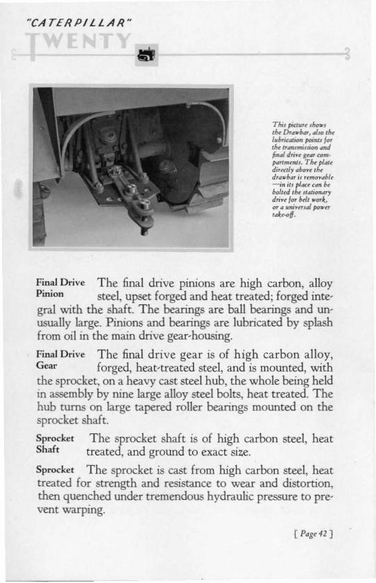
ThUpfct..»e .100.,llw Dr_.... ._$<I tlwI"bric_ poOlIl, f...1M h..umilliOfl...,J,rwl Jri.~ KtOfF com·".,.tmmll. Thr pl",uJi,rctl, ,,"-r 'hrd,,,, ."", i. ,rm"""b!r--i" jl, pldCt u n btboluJ tht ' 14'; 0" ,",dri"r /'" lui, .1: .ar '" tt.,."n.,J po nrdr.<>6·
Final Drive T he final drive pinions are high carbon, alloyPinion steel, upset forged and heat treated; forged integral with the shaft. T he bearings are ball bearings and unusually large. Pinions and bearings are lubricated by splashfrom oil in the main drive gear-housing.
Final Drive The final drive gear is of hi gh carbon alloy,Geac forged, heat-treated steel, and is mounted, withthe sprocket, on a heavy cast steel hub, the whole being heldin assembly by nine large alloy steel bolts, heat treated. Thehub turns on large tapered roller bearings mounted on thesprocket shaft.
Sprocket The sprocket shaft is of high carbon steel, heatShaft treated, and ground to exact size,
Sprocket The sprocket is cast from high carbon steel, heattreated for strength and resistance to wear and distortion,then quenched under tremendous hydraulic pressure to pre'vent warping.
[ Pagr 4Z]

" CATE R P I L LA R"
M iscellaneous EquipmentSeat The comfort of the operator has been thoughtfullyconsidered in the design of the tractor. A wide, well-cushioned seat is bo lted above the transmission case) so that thedriver is within easy reach of levers, foot pedals and inletmanifold heat control.
Fenders Heavy steel fenders are standard equipment, givingmaximum protection to the operator and also forminga deckupon which cab or summer top may be mounted withoutdisarranging any parts.
Tools Adequate tool equipment is furnished, ample in variety to make changes and adjustments in the field. The toolsare carried in a container under the seat cushion.
[ P<lgt 4J ]

"CA TER PILLAR "
SpecificationsENG IN E-Bore. 4"; st roke, 5!.1z '" ; R.P.M.• 1100.
VALVES-Exhaust. head diameter, I 23/32'"; stem diameter. 7/16 '" , Inlet.head diameter, I 29/ 32'" ; stem diameter, 7/1 6'" ,
CRAN K SHAFT- Diameter , 2.50'" ,
CAM SHAFT-Bearings. diameter, 2.25'".
PISTO NS-Diameter, 4'". Length. 5.25'", Rings, J;8".PISTON PIN Diameter. 15 0"',
FAN- BlAdes. 6. f an diameter. 20",
BRA KES-Drum diameter, l l }'s". Band wid th, 3"'.
FUEL-Gasoline. (I n count ries where gasoline is unobtainable or where itsprice is unduly high in comparison with other locally obtainable fuels,distillate, kerosene, alcohol. etc., can be used. Information regard ing theuse of such fuels furnished on request.)Fuel ta nk of 22 gallons capacity .
FLYW HEEL CLUTCH-Drives upper trans mission shaft th rough all -metaldouble universal connection. T wo friction surfaces. C lutch plates, 14"diameter . Friction surface area, 115 sq. in.
TRANSMISSiON- Selective gear type, three speeds forward and one reverse.Single reduction in all forwa rd speeds.
ST EERING-No. of plates in each clutch, 16 . No. of springs, 8 . Diametermoulded lining, IO!!4". Area friction surface each plate, 44 sq. in.
FINAL DR IVE GEARS-Pitch, 5. Diameter assembling holts, %". No. ofbolts, 9.
SPROCKET - No. of teeth, 2'). Diameter of face, 2!4'". No. of bolts, 9.Diameter of bolts, %'".
TRACK-Width of t rack shoe (standard) , I I " . Height of integral grouser,2!!4". Diameter of track shoe bolts, Yz". Diameter of track pin, 1 5/1 6" .Diameter of track pin bushings, 2" .
GREASE PUMP - Capacity, 2') lbs.
RAT INGS-Engine speed, 1100 R.P.M. Drawbar horsepower, 20 . Belt horsepower, 25.
SPEEDS-low, 1.79 M.P.H. Intermediate, 3.07 M.P.H. High, 4.67 M.P.H.Reverse, 2.26 M.P.H.

NCA T E R P I L L A R "
DlMENSIONS-Owr-all length, II U~. Over-all width. 6 1'". Over-all height ,60.,.", Tread. 42", Ground clearance under transmission , 12". Dra.wbarheight above ground. 1S~" .
N ET WEIG HT (A pproximate) - 7,OOO 1bs.
SHIPPING WEIGHT (A pproximate) - 7,500 lbs.
Special EquipmentVarious items of special equipment to meet a wide range
of requirements are available for installation either at the"Caterpillar" plants or in the field.
Reference has already been made to the fact that specialtrack shoes may be ordered in place of the standard l l -inchshoe. Following is a list of other special equipment and theservice for which intended:SPARK ARRESTER-A spar k arres ter offers maximum protection against
the possibility of sparks coming from th e exhaust .
FRONT PU LL HOOK-A front pull hook is often useful for pulling loadsin reverse gear.
LIGHTING EQUIPMENT-p(m·erful headlights. with brackets and necessary >."i ring, can be furnished applied at the plant. or boxed for field installation. Bracket holt holes are tapped into radiat or side plates and inthe fend ers at the rear of th e tractor, to enable the owne r to locatelights to suit his convenience. Cu rrent for the light ing system can be furnished either direct from a generator, or by a generator and storage h.lttery system.
STATIONARY DRIVE UN IT-For belt work, a stationary dri ve can beattached to the rear of the transmission case. This unit connects directlywith the upper trans mission shaft.
POWER T A KE·OFF- For use with various equipment that is designed to beoperated by, as well as pulled by, a tractor, the T wenty can be equippedwith power rake-off at either the fron t or rear .
SUMMER TOP AND C LOS ED CAB-Summer top and cab equipment forthe Twenty is of the quickly convertible type. The summer top consistsof angle iron fra me and curved top over th e driver's seat . T his is easily
[ Pagt45 ]

· CA TER P I L L A R "
converted into a completely enclosed cab by the addition of sides anddoors or curtains.
ELECTRIC ST ARTE R- An electric starter, ""rith a floor button, startingmotor and starter flywheel ring , can be installed. It is best to order thisequipment atta ched at the "Ca terpillar" plants; but starter ring shru nkupon the flywheel. together with motor and accessories, can be suppliedfor field installation. T he use of an electric starte r, of course, necessitatesthat the t ractor also he equipped with generato r and hattery, which canhe used both for the starter and the lights.
STREET PLATE For conditions that make the use of a smooth tra ck sur-face necessary or desirab le. st reet plates can be furni shed. These platesbolt to th e standa rd shoes and provi de a flat ground contact withoutprojecting grousers or bolt heads.
MUFFLER - The Twenty can be equi pped \\'1th a muffler on th e exhaust.
ODOMETER-To aid those tra ctor users who desire to keep accurate workrecords or cost records. the Twenty can be fined with an odo meter.which registers distance traveled. in miles.
A LCO HO L CARBURETOR-A special carburetor for use when alcohol isused as fuel.
[ P4g~ "6 ]