Catalytic Filter for Dioxin Control - Experience and Case...
50
1 1 Catalytic Filter for Dioxin Control Catalytic Filter for Dioxin Control - - Experience and Case Studies Experience and Case Studies Zhengtian Xu W.L. Gore & Associates, Inc. Remedia is a trademark of W.L. Gore & Associates, Inc.
Transcript of Catalytic Filter for Dioxin Control - Experience and Case...

1
1
Catalytic Filter for Dioxin ControlCatalytic Filter for Dioxin Control
-- Experience and Case StudiesExperience and Case Studies
Zhengtian XuW.L. Gore & Associates, Inc.
Remedia is a trademark of W.L. Gore & Associates, Inc.

2
2
AgendaAgenda
• Technology Introduction
• Application Experience: ProvenPerformance Worldwide
– IVRO Municipal Waste Incinerator-Belgium
– Phoenix Medical Waste Incinerator-USA
– Secondary Aluminum Production Plant-UK
– Ashibe Municipal Waste Incinerator - Japan
• Conclusions

3
3
Dioxin Control TechnologiesDioxin Control Technologies
• Powder Activated Carbon (PAC)injection
• Selective Catalytic Reduction (SCR)
• Catalytic filters

4
4
Carbon injection
Boiler
ESP
Lime
Bag House
StackFurnace
PAC InjectionPAC Injection –– Process DiagramProcess Diagram

5
5
PAC InjectionPAC Injection
• Injection of PAC up stream of baghouse
• Most D/F captured at the filter bag
• Transfer D/F from gas to solid phase
• Efficiency varies based on injection rate
• Proven and reliable

6
6
PAC InjectionPAC Injection
• Move D/F from air to solid waste
• Increase disposal cost
• Active system - high maintenance
• Safety - hot spots in filter house
• Large area required for carbon silo

7
7
Boiler
Lime
Bag House
StackFurnace
SCRHeat
Selective Catalytic ReductionSelective Catalytic Reduction

8
8
Selective Catalytic Reduction
• High equipment & catalyst cost
• High temperature requirement(>250 °C)
• High pressure loss - energy costs
• Large footprint for catalyst house
• Vulnerable to dust

9
9
Remedia Catalytic Filter SystemRemedia Catalytic Filter System

10
10
• Reduces the total Dioxin released tothe environment
• Easy to adopt and use
• Cost effective
• Provides reliable & consistentoperation
Why REMEDIA Filter??Why REMEDIA Filter??

11
11
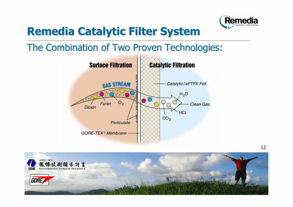
Remedia Catalytic Filter SystemRemedia Catalytic Filter System
12
12
Remedia Catalytic Filter SystemRemedia Catalytic Filter System
The Combination of Two Proven Technologies:The Combination of Two Proven Technologies:

13
13
Uncatalyzed
reaction
Products
Catalyzed
reaction
Ea. (uncat)
Ea. (cat)
E
n
e
r
g
y
Reaction Pathway
CatalysisCatalysis

14
14
TiO2V2O5
O
O2
3
1
4 6
7
8
9
Clx Cly
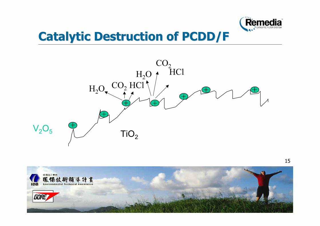
Catalytic Destruction of PCDD/FCatalytic Destruction of PCDD/F
15
15
TiO2
V2O5
CO2
CO2
H2O
H2OHCl
HCl
Catalytic Destruction of PCDD/FCatalytic Destruction of PCDD/F

16
16
• PCDDsC12HnCl8-nO2 + (9+0.5n)O2 ==>(n-4) H2O + 12 CO2 + (8-n) HCl
• PCDFsC12HnCl8-nO + (9.5+0.5n)O2 ==>(n-4) H2O + 12 CO2 + (8-n) HCl
Catalytic Destruction of PCDD/FCatalytic Destruction of PCDD/F

17
17
REMEDIA Catalytic FilterREMEDIA Catalytic Filter
• High PCDD/F removal efficiency
• Destruction of the PCDD/F molecule
• Lower disposal cost
• Passive system
• Low temperature requirement (150-250°C)
• Use existing filter house
• Lower pressure loss - energy costs

18
18
REMEDIA Catalytic Filter System is an evolution of 2 proven technologies:…………….
REMEDIA Catalytic Filter in ActionREMEDIA Catalytic Filter in Action
& CatalysisSurface Filtration

19
19
RawGas
< 0.1
ng/Nm³Dioxin
Highly ContaminatedDioxin/Waste
Adsorption Process
Less Waste to Landfill> 90% Dioxin Destroyed
REMEDIA Catalytic Filter System
Remedia Catalytic Filter vs. AdsorptionRemedia Catalytic Filter vs. Adsorption
RawGas
< 0.1
ng/Nm³Dioxin
ActivatedCarbon

20
20
CatalyticTower
SCR Catalytic Reactor System REMEDIA CatalyticFilter System
Remedia Catalytic Filter vs. Catalytic ReactorRemedia Catalytic Filter vs. Catalytic Reactor
RawGas
RawGas
< 0.1
ng/Nm³Dioxin
Re-HeatSystem
< 0.1
ng/Nm³ Dioxin

21
21
AgendaAgenda
• Technology Introduction
• Application Experience: ProvenPerformance Worldwide
– IVRO Municipal Waste Incinerator-Belgium
– Phoenix Medical Waste Incinerator-USA
– Secondary Aluminum Smelter-UK
– Ashibe Municipal Waste Incinerator - Japan
• Conclusions

22
22
• Municipal Waste Incinerators
• Medical Waste Incinerators
• Industrial Waste Incinerators
• Pyrometallurgical
• Crematoriums
Worldwide REMEDIA CatalyticWorldwide REMEDIA Catalytic
Filter System ApplicationsFilter System Applications

23
23
Worldwide Proven PerformanceWorldwide Proven Performance
Creative TechnologiesWorldwide

24
24
Worldwide Proven PerformanceWorldwide Proven Performance
0
1
2
3
4
5
6
7
8
Dio
xin
TLB IVBO Karume Ashibe Phoenix Kasugai
Before Remedia
After Remedia
Dio
xin
(n
g T
EQ
/Nm
3)

25
25
• Over 50 applications worldwide meetingthe most stringent emission regulations.
• Applications in 10 countries.
• Over 130 years cumulative globalexperience.
• Thousands of successfulmeasurements.
Proven Performance You Can Rely OnProven Performance You Can Rely On
26
26
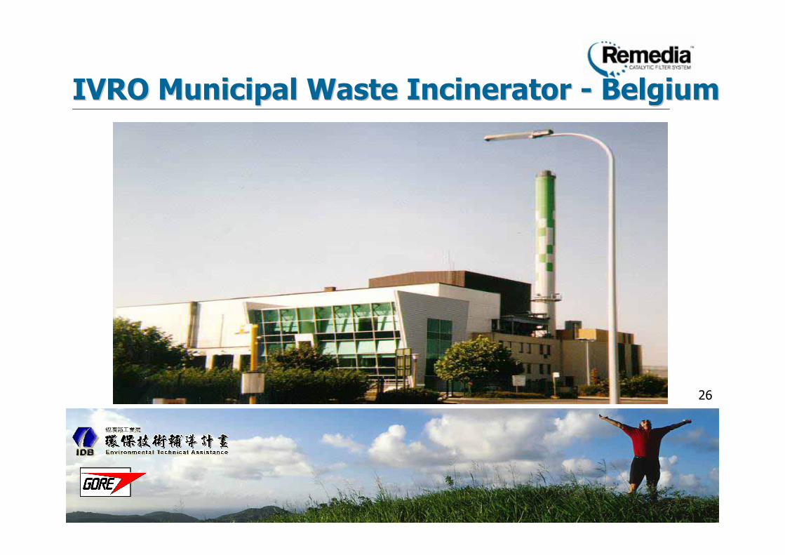
IVRO Municipal Waste IncineratorIVRO Municipal Waste Incinerator -- BelgiumBelgium

27
27
IVRO Municipal Waste IncineratorIVRO Municipal Waste Incinerator

28
28
Reliable PerformanceReliable Performance

29
29
RawGas
Adsorption Process REMEDIA Catalytic Filter System
IVRO Comparison TestingIVRO Comparison Testing
RawGas
ActivatedCarbon
1ngTEQ/Nm3

30
30
• Over 10 measurements, gas phase dioxinsaveraged 75% of total.
• Dioxin emissions well below 0.1 ngTEQ/Nm3 for over 6 years.
• Gas phase dioxin destruction greater than99% for all isomers.
• Dust emissions less than 0.4 mg/Nm3
• Only Belgian incinerator to have never beenshut down for dioxin.
IVRO ResultsIVRO Results

31
31
Baltimore Regional Medical WasteBaltimore Regional Medical Waste
IncineratorIncinerator -- USAUSA

32
32
• Largest dedicated facility in the world
• Capacity: two incineration process lines,each rated at 77 metric tons per daythroughput
• Service area: within a radius ofapproximately 400 kilometers fromBaltimore, Maryland
Plant InformationPlant Information
33
33
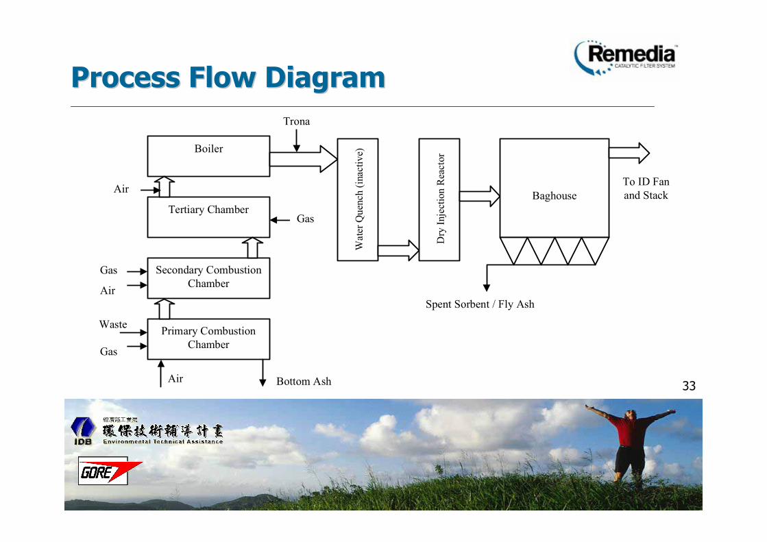
Process Flow DiagramProcess Flow Diagram
Primary Combustion
Chamber
Secondary Combustion
Chamber
Tertiary Chamber
Boiler
Wat
er Q
uen
ch (
inac
tiv
e)
Dry
Inje
ctio
n R
eact
or
Baghouse
Trona
Bottom Ash
Spent Sorbent / Fly Ash
To ID Fan
and Stack
Gas
Waste
Gas
Gas
Air
Air
Air

34
34
• Phoenix Introduced to Catalytic Filter Technologyby Gore in Late 1997
• Advantages Compared with PAC Injection
• Destruction vs. Adsorption
• Passive Solution, No Active Chemical Feeding
• Conversion is Simple (Install New Filters)
• Reduction of Potential Future Liability
• Advantages of ePTFE Filter Media
• Phoenix Refitted Both Baghouses with CatalyticFilters in May - June 1999
Control Technology EvaluationControl Technology Evaluation

35
35
Measurement Results: PCDD/FsMeasurement Results: PCDD/Fs
0.098
3.35
0.0550
1
2
3
4
RUN 1 RUN 2
PC
DD
/F C
on
cen
trati
on
(ng
TE
Q/d
scm
@ 7
% O
2)
RAW GAS
CLEAN GAS

36
36
Measurement Results: PCDD/FsMeasurement Results: PCDD/Fs
5.5
2.3
0.077
2.3
0
1
2
3
4
5
6
7
Historical
Value (1998)
New
Emission
Guideline
Guaranteed
Value
Catalytic
Filter (mean)
Cle
an
Ga
s
PC
DD
/F C
on
ce
ntr
ati
on
(ng
TE
Q/d
scm
@ 7
% O
2)

37
37
• Overall, 98.4% of PCDD/F (gas + solidphase) were removed– 97.7% of gas phase PCDD/F were destroyed
– 99.9% of solid phase PCDD/F were removed
• PCDD/F emission < 0.1 ng TEQ/dscm
• 99.95% of the particulate was removed
Key FindingsKey Findings

38
38
Secondary Aluminum Production PlantSecondary Aluminum Production Plant -- UKUK
39
39
Process Flow DiagramProcess Flow Diagram
shredder decoater
incineratorheat
exchanger
melting furnaceAl shreds
dilution air
cans
bag house
raw gas
sampling port
clean gas
sampling portdilution air
fan
fan
temperature
after fan
40
40
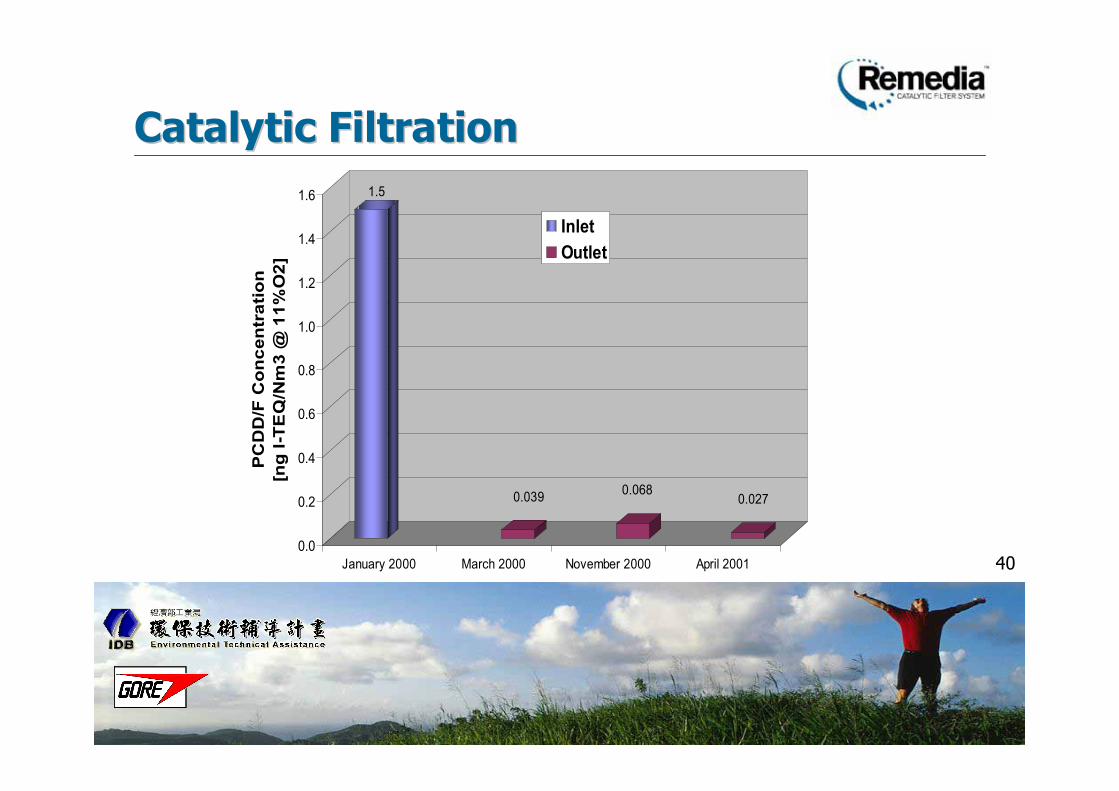
Catalytic FiltrationCatalytic Filtration
1.5
0.0390.068
0.027
0.0
0.2
0.4
0.6
0.8
1.0
1.2
1.4
1.6
PC
DD
/F C
on
cen
tra
tio
n
[ng
I-T
EQ
/Nm
3 @
11
%O
2]
January 2000 March 2000 November 2000 April 2001
Inlet
Outlet

41
41
• Successful operation for more than 4years
• Total removal efficiency more than97%
ResultsResults

42
42
Ashibe Municipal Waste IncineratorAshibe Municipal Waste Incinerator -- JapanJapan

43
43Fig. Scheme of Ashibe MSWI
Heat
Exchanger
Induced
Draft Fan
Gas C
oo
ler Baghouse
Furnace
Lime
Injection
sta
ck

44
44
0
2
4
6
8
10
12
PC
DD
/F [
ng
WH
O-T
EQ
/N
m3
@ 1
2%
O2]
Start-Up Steady State Shut-Down
Inlet
Outlet
Dioxin Destruction vs. Operating ConditionDioxin Destruction vs. Operating Condition

45
45
0.020 0.018 0.021
3.1
4.5
7.5 1.7
3.9
0.79
0.003 0.001 0.003
0
2
4
6
8
10
12
Start-up Normal Shut-down
IN OUT IN OUT IN OUT
Particulate phase
Gas phase
PC
DD
/F,
ng
WH
O-T
EQ
/m
3N
@12%
O2

46
46
T4C
DD
s
P5C
DD
s
H6C
DD
s
H7C
DD
s
O8C
DD
s
T4C
DF
s
P5C
DF
s
H6C
DF
s
H7C
DF
s
O8C
DF
s
BH outlet
0
20
40
60
80
100
120
140
160
BH inlet
PC
DD
/F
(ng
/ N
m3
@12%
O2)
Dioxin Isomer Distribution: Inlet/OutletDioxin Isomer Distribution: Inlet/Outlet

47
47
• Greater than 99.5% dioxin control for alllevels of inlet concentration.
• Effective dioxin destruction for all stages ofdaily batch process.
• Consistent and efficient destruction of all TEQisomers.
• All dioxin emission values significantly below0.1 ng regulation.
Ashibe ResultsAshibe Results

48
48
AgendaAgenda• Technology Introduction
• Remedia Filter Bag Processing
• Application Experience: ProvenPerformance Worldwide– IVRO Municipal Waste Incinerator-Belgium
– Phoenix Medical Waste Incinerator-USA
– Secondary Aluminum Production Plant-UK
– Ashibe Municipal Waste Incinerator - Japan
• Conclusions

49
49
Remedia Catalytic Filter BagRemedia Catalytic Filter Bag
• Reduces the totalDioxin released to theenvironment
• Easy to adopt and use
• Cost effective
• Provides reliable &consistent operation
Remedia Catalytic Filter Bag

50
50
Industry RecognitionIndustry Recognition
2001 Environmental2001 Environmental
InnovationInnovation
Product of theProduct of the
Year AwardYear Award
2002 J. Deane2002 J. Deane
Sensenbaugh AwardSensenbaugh Award
OutstandingOutstanding
Achievement in theAchievement in the
Field of Air PollutionField of Air Pollution
ControlControl