Catalyst support effects in the growth of structured carbon from the decomposition of ethylene over...
14
Journal of Catalysis 221 (2004) 386–399 www.elsevier.com/locate/jcat Catalyst support effects in the growth of structured carbon from the decomposition of ethylene over nickel Colin Park 1 and Mark A. Keane ∗ Department of Chemical and Materials Engineering, University of Kentucky, Lexington, KY 40506-0046, USA Received 26 June 2003; revised 21 August 2003; accepted 22 August 2003 Abstract The characteristics of carbon nanofibers generated during ethylene decomposition over supported nickel can be readily manipulated by a judicious choice of the support material. The occurrence and ramifications of Ni/support interaction(s), in terms of Ni particle size/morphology/orientation, are considered and related to the carbon structure/dimensions and yield. A 7 ± 1% w/w Ni loading was achieved by standard impregnation of SiO 2 , Al 2 O 3 , MgO, Ta 2 O 5 , activated carbon (AC), and graphite: the reduced catalysts have been characterized by H 2 chemisorption, CO chemisorption/temperature-programmed desorption (TPD), and high-resolution transmission elec- tron microscopy (HRTEM). The reaction of ethylene with hydrogen over these catalysts also generated ethane via hydrogenation, a step that was favored over Ni/Al 2 O 3 and Ni/MgO. Carbon yield (where T< 800 K) increased in the sequence Ni/Al 2 O 3 ∼ Ni/MgO < Ni/AC < Ni/graphite < Ni/Ta 2 O 5 < Ni/SiO 2 ; at higher temperatures (> 850 K), Ni/AC and Ni/graphite delivered the highest yields. With the excep- tion of Ni/graphite and Ni/Ta 2 O 5 , which produced helical and highly curved fibers, the other supported Ni catalysts generated a relatively straight (limited curvature) fibrous growth. The occurrence of Ni fragmentation and secondary fiber growth from such fragments is illustrated and discussed. The influence of H 2 content in the feed was investigated with respect to both carbon yield and structure; an increased H 2 con- tent served to enhance fiber structural order. Temperature-programmed oxidation studies have been used to probe the graphitic nature of the carbon product; the results are consistent with HRTEM analysis. 2003 Elsevier Inc. All rights reserved. Keywords: Carbon nanofibers; Ethylene decomposition; Supported nickel 1. Introduction Modification to the properties of supported metals through the choice of substrate is not a new concept. As early as the 1930s it was recognized that the presence of highly charged cations on an oxide surface altered the cata- lytic properties of supported metals [1]. The use of a sup- port to disperse a chosen metal is not only of economic benefit (lower preparation costs/longer productive lifetime) but the substrate can also influence catalyst performance through electronic interaction(s), spillover, and migration effects [2–5]. Electronic perturbation is most aptly demon- strated in the case of TiO 2 [6,7], leading to dramatic changes in the chemisorptive capacity of Pt, Rh, Pd, and Ir [8]. * Corresponding author. E-mail address: [email protected] (M.A. Keane). 1 Current address: Synetix, P.O. Box 1, Belasis Avenue, Billingham, Cleveland, TS23 1LB, UK. The impact on chemisorption also extends to Fe, Ni, and Co but the consensus of opinion is that higher reduction temperatures are needed to induce “strong metal/support interactions” (SMSI) with these metals [9–11]. Since the pi- oneering work on SMSI dating from the late 1970s [8,12], the use of supports to induce changes in the catalytic behav- ior of dispersed metals has been the subject of a number of reports [4,6,7,13,14]. The generation of ordered carbonaceous structures (ful- lerenes, nanotubes, and nanofibers) is a burgeoning area of catalysis research [15–20]. The unique chemical and physi- cal properties associated with carbon nanofibers, the focus of this study, can be put to good effect in diverse applications, i.e., as catalyst supports [13,16,21–23], polymer reinforce- ment agents [24], fuel cell electrodes [25], adsorbents [26], and in energy storage [18]. Carbon nanofibers can be read- ily generated from mono- and bimetallic catalysts via the decomposition (723 K T 923 K) of a range of carbon- containing compounds [16,20,27,28]. There is ample evi- 0021-9517/$ – see front matter 2003 Elsevier Inc. All rights reserved. doi:10.1016/j.jcat.2003.08.014
-
Upload
colin-park -
Category
Documents
-
view
214 -
download
1
Transcript of Catalyst support effects in the growth of structured carbon from the decomposition of ethylene over...

t
anipulatedparticle
beenion elec-a step that
ep-latively
llustratedHature of the
Journal of Catalysis 221 (2004) 386–399www.elsevier.com/locate/jca
Catalyst support effects in the growth of structured carbonfrom the decomposition of ethylene over nickel
Colin Park1 and Mark A. Keane∗
Department of Chemical and Materials Engineering, University of Kentucky, Lexington, KY 40506-0046, USA
Received 26 June 2003; revised 21 August 2003; accepted 22 August 2003
Abstract
The characteristics of carbon nanofibers generated during ethylene decomposition over supported nickel can be readily mby a judicious choice of the support material. The occurrence and ramifications of Ni/support interaction(s), in terms of Nisize/morphology/orientation, are considered and related to the carbon structure/dimensions and yield. A 7± 1% w/w Ni loading wasachieved by standard impregnation of SiO2, Al2O3, MgO, Ta2O5, activated carbon (AC), and graphite: the reduced catalysts havecharacterized by H2 chemisorption, CO chemisorption/temperature-programmed desorption (TPD), and high-resolution transmisstron microscopy (HRTEM). The reaction of ethylene with hydrogen over these catalysts also generated ethane via hydrogenation,was favored over Ni/Al2O3 and Ni/MgO. Carbon yield (whereT < 800 K) increased in the sequence Ni/Al2O3 ∼ Ni/MgO < Ni/AC <
Ni/graphite< Ni/Ta2O5 < Ni/SiO2; at higher temperatures (> 850 K), Ni/AC and Ni/graphite delivered the highest yields. With the exction of Ni/graphite and Ni/Ta2O5, which produced helical and highly curved fibers, the other supported Ni catalysts generated a restraight (limited curvature) fibrous growth. The occurrence of Ni fragmentation and secondary fiber growth from such fragments is iand discussed. The influence of H2 content in the feed was investigated with respect to both carbon yield and structure; an increased2 con-tent served to enhance fiber structural order. Temperature-programmed oxidation studies have been used to probe the graphitic ncarbon product; the results are consistent with HRTEM analysis. 2003 Elsevier Inc. All rights reserved.
Keywords:Carbon nanofibers; Ethylene decomposition; Supported nickel
als. Ase oataup-mice)
anceionon-s
8].
am,
andtionportpi-2],hav-er of
(ful-ea ofysi-
us ofns,
rce-26],ead-the-evi-
1. Introduction
Modification to the properties of supported metthrough the choice of substrate is not a new conceptearly as the 1930s it was recognized that the presenchighly charged cations on an oxide surface altered the clytic properties of supported metals [1]. The use of a sport to disperse a chosen metal is not only of econobenefit (lower preparation costs/longer productive lifetimbut the substrate can also influence catalyst performthrough electronic interaction(s), spillover, and migrateffects [2–5]. Electronic perturbation is most aptly demstrated in the case of TiO2 [6,7], leading to dramatic changein the chemisorptive capacity of Pt, Rh, Pd, and Ir [
* Corresponding author.E-mail address:[email protected] (M.A. Keane).
1 Current address: Synetix, P.O. Box 1, Belasis Avenue, BillinghCleveland, TS23 1LB, UK.
0021-9517/$ – see front matter 2003 Elsevier Inc. All rights reserved.doi:10.1016/j.jcat.2003.08.014
f-
The impact on chemisorption also extends to Fe, Ni,Co but the consensus of opinion is that higher reductemperatures are needed to induce “strong metal/supinteractions” (SMSI) with these metals [9–11]. Since theoneering work on SMSI dating from the late 1970s [8,1the use of supports to induce changes in the catalytic beior of dispersed metals has been the subject of a numbreports [4,6,7,13,14].
The generation of ordered carbonaceous structureslerenes, nanotubes, and nanofibers) is a burgeoning arcatalysis research [15–20]. The unique chemical and phcal properties associated with carbon nanofibers, the focthis study, can be put to good effect in diverse applicatioi.e., as catalyst supports [13,16,21–23], polymer reinfoment agents [24], fuel cell electrodes [25], adsorbents [and in energy storage [18]. Carbon nanofibers can be rily generated from mono- and bimetallic catalysts viadecomposition (723 K� T � 923 K) of a range of carboncontaining compounds [16,20,27,28]. There is ample

C. Park, M.A. Keane / Journal of Catalysis 221 (2004) 386–399 387
f theonicon-s (upeessringwerhis(upIt
, us-eldslic
Nith
washeforfze-
th acar-eenam-ca-nal
Nibonure;orkrang
ya-rear-
n
sed.romer)er-
Othat
ness
t ag-theiffi-atenedtryHFata-inedre,rere
ter-led,a
r-
ctiv-the
sat-ken
-tsedfmedhes of) to. Ni-ut atca-
erich
tureoredell
nt toted
ed
o-
a-m-ess-1
dence to show that the dimensions/lattice orientations ocarbon product are governed by the dimensions/electrstructure of the catalytic metal particles [16,29]. Use of nsupported metal(s) can generate significant carbon yieldto 250 gC/gcat) but there is little or no control over thdiameter of the nanofiber [16,20,28]. One way to addrthis failing is through the use of supported catalysts beasmaller metal particles that promote the growth of narroand more uniformly sized fibers [30,31]. A drawback to tapproach has been the relatively low yields of carbonto 2 gC/gcat) that have been typically produced [31–35].should, however, be noted that Avdeeva and co-workersing coprecipitated Ni–alumina, have recorded carbon yi(up to 250 gC/gcat) similar to those generated by metalpowders [36,37].
In a recent study [30], we evaluated the application ofsupported on Y zeolite and silica for the controlled growof ordered carbon nanofibers. While carbon productionlimited by the interconnecting microporous network of tzeolite, the carbon morphology/structure was similarboth Ni/zeolite and Ni/SiO2, albeit a sharper distribution onarrower fibers was generated from the Ni-impregnatedolite. A search through the literature has failed to unearcomprehensive examination of the role of the support inbon growth from Ni. The published studies have largely bfocused on the use of SiO2, Al2O3, and graphite to supportvariety of metals [24,31–36,38,39]. In this paper, we exaine the role that Ni/support interaction(s) can play in thetalytic decomposition of ethylene to carbon. An intentioinducement of electronic perturbations in the dispersedby varying the nature of the support should impact on carfiber dimensions and/or morphology and/or lattice structcontrol of such effects is the premise on which this wis based. We have considered an array of substrates,ing from a basic MgO to conventional Al2O3 and SiO2, aswell as Ta2O5, a highly refractive oxide that exhibits manof the qualities of TiO2 [12,40]. The use of graphite, a mterial known [38] to induce SMSI, and a high surface aactivated carbon (AC) with little or no metal/support inteaction have also been investigated.
2. Experimental
2.1. Catalyst preparation, activation, and characterizatio
The SiO2 (fumed), Al2O3, Ta2O5, and MgO substratewere supplied by Sigma-Aldrich and used as receivThe activated carbon (G-60, 100 mesh) was obtained fNORIT (UK) and the graphite (synthetic 1–2 µm powdfrom Sigma-Aldrich. Both carbonaceous materials undwent a demineralization (continuous agitation in 1 M HN3for up to 7 days) to remove any residual metal impuritiescould contribute to the catalytic step. The Ni-loaded (7±1%w/w) samples were prepared by standard incipient wetimpregnation where a 2-butanolic Ni(NO3)2 solution was
-
added dropwise at 353 K to the substrate with constanitation (500 rpm). Aqueous solutions were not used ascarbon support materials are hydrophobic, leading to dculties with surface wetting that can impact on the ultimmetal dispersion [22,26,41]. The Ni content was determi(to within ±3%) by atomic absorption spectrophotome(VarianSpectra AA-10); the samples were digested in(37% conc.) overnight at ambient temperature. The clyst precursors were subsequently dried at 383 K, calc(10 K/min) in air at 623 K, cooled to ambient temperatuand heated (10 K/min) to the ultimate reaction temperatuin 20% v/v H2/He. Samples for off-line TEM analysis wecooled (in He) and passivated in a 2% v/v O2/He mixture atroom temperature.
H2 and CO chemisorption were employed to characize the supported Ni sites where the catalyst was coofollowing the reduction step, to 298 K in dry He andfixed volume (10 µl) of H2 or CO pulsed into the He carier gas stream; the concentration of H2 or CO exiting thereactor was measured using an on-line thermal conduity detector (TCD). The injections were repeated untildownstream peak area was constant, indicating surfaceuration. A subsequent series of calibration peaks were taat ambient temperature to quantify H2 or CO uptake; reproducibility was better than±3%. The CO-loaded catalyswere thoroughly flushed with dry He for 1 h and ramp(TPD at 25 K/min) to 1073 K with continual monitoring othe exiting gas; data acquisition and analysis were perforusing the JCL 6000 (for Windows) software package. Tbed temperature was continuously monitored by meana data logging system (Pico Technology, Model TC-08give an accurate measure of the desorption temperaturetrogen BET surface area measurements were carried o77 K (Autosorb-1-C, Quantachrome) on freshly reducedtalysts.
2.2. Catalytic carbon growth procedure/carboncharacterization
All catalytic reactions were carried out under atmosphpressure, in situ following the activation step (and a 1He flush), in a fixed-bed silica reactor over the temperarange 673–898 K. The reaction temperature was monitcontinuously by a thermocouple inserted in a thermowwithin the catalyst bed; catalyst temperature was constawithin ±2 K. The catalytic measurements were conducwhereW/Q = 0.5–2× 10⁻⁵ g/(cm3 h−1): W = weight ofactivated catalyst;Q = inlet volumetric C2H4 feed rate. Theoverall gas hourly space velocity (GHSV) was maintainat a constant 11,300 h−1 with a C2H4/H2 molar ratio in therange 1/4 to 4/1. One set of reaction conditions was chsen to assess the performance of each catalyst: C2H4/H2 =4/1 v/v; T = 773 K; t = 1 h. The effluent gas was anlyzed by on-line capillary chromatographyusing an AI Cabridge GC94 chromatograph equipped with a split/splitlinjector and a flame ionization detector, employing a DB

388 C. Park, M.A. Keane / Journal of Catalysis 221 (2004) 386–399
i-rvalcon-. The
ble30]entaral
bseassis,
up toere
talysy
ofhor-siblewnped
stentlereinercar%),
s beopyrod-
i-Thetan
ontobonudyarti-opyionam-and
CO
so-
en in
thenta-
ib-t arfa-area
b-andges
tice)sit-sentd-
g. 1aic oftri-theat
atedtri-ionren of
ox-46]y ofdle-linebon,acethat
ands inrac-
50 m× 0.20 mm i.d., 0.33 µm capillary column (J&W Scentific). The gaseous stream was sampled at regular inteby means of a heated gas-sampling valve and all internecting tubing was maintained at elevated temperaturescatalyst was contacted with the C2H4/H2 mixture for 1 hto achieve a uniform carbon growth with no appreciapressure deviations/flow disruption. Preliminary studies [established that this reaction time generated a represtive carbon growth that could be linked to catalyst structucharacteristics in a meaningful way. The reactor was suquently cooled to ambient temperature and the sample pvated in a 2% v/v O2/He mixture before any weight changedue to carbon deposition, was determined. Repeated (five) catalytic runs generated product compositions that wreproducible to better than±7%. The yield of solid carbon(YC) was calculated using the following expression
YC = (C2H4)input − (CH4/2+ C2H4 + C2H6)output
(C2H4)input
and is expressed in this paper as gram C per gram ca(or Ni). The selectivity in terms of (say) ethane is given b
SC2H6 (%) = YC2H6∑(CH4 + C+ C2H6)output
× 100.
Temperature-programmed oxidation (TPO) profilesthe catalytically generated carbon were obtained from toughly washed, demineralized samples to avoid any poscatalyzed gasification of carbon by residual Ni. A knomass (ca. 100 mg) of a demineralized sample was ram(25 K/min) from room temperature to 1198 K in a 5% v/vO2/He mixture with on-line TCD analysis of the exhaugas; the catalyst bed temperature was again independmonitored using the TC-08 data logger. These profiles wcompared against those generated for conventional demalized carbon systems, i.e., the graphite and amorphousbon that served as Ni supports. All gasses (He (99.99C2H4 (99.95%), H2 (99.99%), and 5% v/v O2/He (99.9%))were dried by passage through activated molecular sievefore use. High-resolution transmission electron microsc(HRTEM) analysis of both the catalysts and the carbon puct was carried out using a Philips CM200 FEGTEM mcroscope operated at an accelerating voltage of 200 kV.specimens were prepared by ultrasonic dispersion in bu2-ol, evaporating a drop of the resultant suspensiona holey carbon support grid. The Ni particle (and carnanofiber)-size distribution profiles presented in this stare based on a measurement of over 500 individual pcles/nanofibers. Analysis by scanning electron microsc(SEM) was carried out using a Hitachi S900 field emissSEM, operated at an accelerating voltage of 25 kV; the sple was deposited on a standard aluminum SEM holdercoated with gold.
s
-
--
t
y
--
-
-
Table 1Nickel loading, surface-weighted average Ni particle size based onchemisorption (dCO), H2 chemisorption (dH) and TEM (dTEM) measure-ments, the characteristic CO TPDTmax values and BET surface areas asciated with the six activated supported Ni catalysts
Catalyst Ni dCO Tmax dH dTEM BET surface(%) (nm) (K) (nm) (nm) area (m2/g)
Ni/SiO2 7 16.3 935 8.2 9.6 203Ni/Al 2O3 6 12.1 878,1013 5.4 5.7 120Ni/AC 6 28.1 716,948, 25.8 23.4 904
1098Ni/graphite 8 84.2 726,898 22.3 27.1 10Ni/MgO 7 8.9 855,925 8.5 10.5 105Ni/Ta2O5 7 68.4 703,848 13.0 15.2 8
TheTmax values associated with the principal desorption peaks are givbold font.
3. Results and discussion
3.1. Characterization of the activated catalysts
The Ni loading, TEM, and CO/H2 chemisorption derivedmean Ni particle diameters and BET surface areas forsix activated catalysts are recorded in Table 1; represetive TEM images are provided in Fig. 1. The size distrution and morphology of the supported Ni particles (acommon Ni loading) are inherent features of the intecial energies associated with each system [42]. Selectedelectron diffraction (SAED) confirmed that the Ni distriuted over each support was present in the metallic formnot as an oxide. Representative high-resolution TEM imaare provided in the inset to Fig. 1 that illustrates the latstructure of Ni dispersed on SiO2. Graphite has a low (BETsurface area with few edge positions available for depoing the metal, which, as a direct consequence, is prein the form of large particles (up to 80 nm) at this loaing [43]. Nevertheless, these particles can be seen in Fito possess well-defined geometrical shapes, diagnostmetal–graphite interaction [42]. Nickel particle-size disbutions, derived from the TEM analysis, are presented inhistograms given in Fig. 2. It is immediately evident thNi supported on either carbonaceous (graphite or activcarbon) substrate exhibits a significantly wider size disbution when compared with the oxide supports. Activatof Ni/MgO led to a dehydration/reduction of MgO, whethe removal of lattice oxygen resulted in a reconstructiothe substrate to generate acicular needle-like magnesiumide, visible in Fig. 1b. It has been shown elsewhere [44–that hydrothermal treatment of MgO generates a diversitmorphologies; the most common being lamellar or neelike with associated defects and irregular intercrystalchannels. Reduction of the Ni-impregnated activated caran essentially amorphous material with a high (BET) surfarea, yielded a metal phase of dimensions comparable toassociated with Ni/graphite, albeit a narrower size rangesmaller average diameter (Table 1). Growth of Ni particlethis case can be attributed to weaker metal/support inte

C. Park, M.A. Keane / Journal of Catalysis 221 (2004) 386–399 389
Fig. 1. Representative TEM images of activated (a) Ni/graphite, (b) Ni/MgO, (c) Ni/AC, (d) Ni/Al2O3, (e) Ni/Ta2O5, and (f) Ni/SiO2. Inset at bottom, HRTEM
images showing the lattice structure of Ni dispersed on SiO2.entonof
atedonis-ter
esti-k byrti-ture
er-
as”-ively
onthatakti-
tion(s), leading to increased Ni mobility and the subsequgreater probability of agglomeration. The weaker Ni–carbinteraction is manifested in the spherical/globular naturethe Ni particles, as shown in Fig. 1c. The Ni phase associwith Al2O3 is characterized by the narrowest distributi(Fig. 2) of smaller crystallites; the nature of the metal dpersion is illustrated in Fig. 1d. The average Ni diamewas the lowest among the six supported catalysts invgated (Table 1), a feature that finds support in earlier worHoang-Van and co-workers [47]. The suppression of pacle growth in this case has been attributed to the ionic na
of the Ni/Al2O3 interaction, leading to an enhanced dispsion of electron-deficient Ni [48]. The Ni phase on Ta2O5is predominately “spread” along the edges of the oxideshown in Fig. 1e, with evidence of faceting and “pill-boxshaped particles, as reported elsewhere [49]. An exclusspherical Ni morphology is in evidence on the SiO2 sup-port (Fig. 1f) in keeping with earlier TEM characterizatireports [50,51]. Previous studies [52,53] have shownNi/SiO2 prepared by impregnation realizes a relatively wemetal/support interaction resulting in Ni growth during acvation.

390 C. Park, M.A. Keane / Journal of Catalysis 221 (2004) 386–399
d
Fig. 2. (a) Ni particle-size distributions associated with freshly activated Ni/Al2O3 (downward hatched bars), Ni/Ta2O5 (solid bars), Ni/MgO (open bars), anNi/SiO2 (cross-hatched bars). (b) Inset, Ni/AC (open bars) and Ni/graphite (solid bars).zes
n exlly
faceingum-s ofendver,suffilysis
uentep-anrat-er-
f CO, Hd Nn in
tter,er-
cies,usenic
COtioneasore
t ingeron
er
ts,n beromorp-on-
leorts
mor-
tosibleis
is-SEM-
h isis
ane
the
There is a decided mismatch in the Ni particle siderived from CO uptake values (dCO) and TEM analysis(dTEM), as revealed in Table 1;dTEM is typically lower thandCO. Such discrepancies suggest some deviation from aclusive 1:1 CO:Ni adsorption stoichiometry, as is normaapplied, i.e., a linear single-point attachment. The surstoichiometry is known to be dependent on metal loadand catalyst composition [54] and there have been a nber of reported instances [55,56] where the dimensionsupported metal particles that are measured differ deping on the analytical technique that is employed. Moreothe TEM approach has a decided disadvantage where incient contrast in the image can hamper an accurate anaAlthough there is an apparent consistency ofdTEM anddCO
values in the case of Ni/MgO, adsorption and subseqdissociation of CO on the MgO are known to give unrresentative results [57–59]. CO interaction with MgO clead to disproportionation and/or oligomerization, geneing CO uptakes with little value in terms of metal dispsion measurements [57,58,60]. The differences indTEM anddCO are particularly pronounced in the case of Ni/Ta2O5,and Ni/graphite, suggestive of a possible suppression ouptake. As an addendum to the particle-size analyses2
chemisorption was also considered and the estimatesizes, based on a 2:1 adsorption stoichiometry, are giveTable 1. The agreement with the TEM results is much bealbeit H2 chemisorption delivers, in the main, smaller avage Ni diameters.
Notwithstanding the apparent CO uptake discrepantemperature-programmed desorption of CO has beento good effect elsewhere [61–63] to probe the electro
-
-
-.
i
d
properties of supported metal particles; the characteristicTPD Tmax values are recorded in Table 1. CO desorpfrom Ni/SiO2 delivered a single characteristic peak wherthe TPD profiles associated with the other catalysts bat least two peaks, one of which predominated. A shifCO TPD to higher temperatures is diagnostic of stronCO/catalyst interactions, which appear to apply to CONi/SiO2, Ni/Al 2O3, and Ni/AC. The predominance of lowT desorption of CO from Ni/graphite and Ni/Ta2O5 (andNi/MgO to a lesser extent) is indicative of SMSI effeci.e., weaker metal/adsorbent interaction. The latter calinked to the anomalous Ni particle sizes generated fCO adsorption on these catalysts. While the CO chemistion/TPD results are by no means conclusive, when csidered along with TEM/H2 chemisorption it is reasonabto state that the Ni phase associated with the six suppconsidered in this study is present in a range of sizes,phologies, and possible electronic perturbations.
3.2. Carbon growth: influence of reaction temperature
The decomposition of ethylene is an attractive routeordered carbonaceous materials as the number of posproducts is limited while the carbon that is generatedtypically of a high purity [64]. The structural charactertics of the carbon product can be assessed from theimages presented in Fig. 3, taking Ni/SiO2 as a representative catalyst; the fibrous nature of the carbon growtimmediately evident. The principal competing reactionhydrogenation to ethane while hydrogenolysis to methoccurs to a lesser extent; trace amounts of C3 and C4 prod-ucts were also detected. Methane was only isolated in
C. Park, M.A. Keane / Journal of Catalysis 221 (2004) 386–399 391
ural
asi-thisylenasduc
e reoms inub-essca-
ure.g-with
0
3
6
the
,66].rted
-2a
s by
ed
Thedm atwnth ofrbonop-
n theudy,ce
Fig. 3. Low (a) and higher (b) resolution SEM images showing structfeatures of carbon fibers grown from Ni/SiO2: T = 773 K; C2H4/H2 =4/1 v/v.
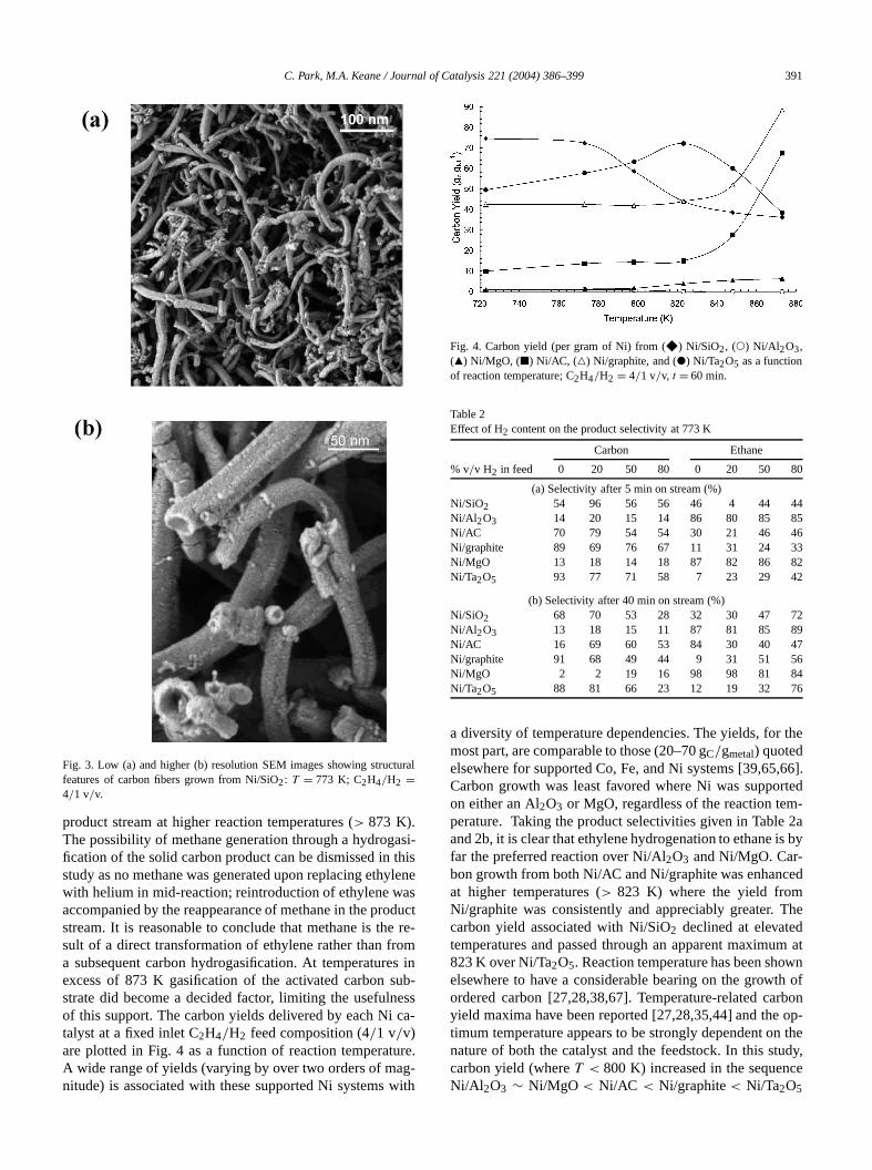
product stream at higher reaction temperatures (> 873 K).The possibility of methane generation through a hydrogfication of the solid carbon product can be dismissed instudy as no methane was generated upon replacing ethwith helium in mid-reaction; reintroduction of ethylene waccompanied by the reappearance of methane in the prostream. It is reasonable to conclude that methane is thsult of a direct transformation of ethylene rather than fra subsequent carbon hydrogasification. At temperatureexcess of 873 K gasification of the activated carbon sstrate did become a decided factor, limiting the usefulnof this support. The carbon yields delivered by each Nitalyst at a fixed inlet C2H4/H2 feed composition (4/1 v/v)are plotted in Fig. 4 as a function of reaction temperatA wide range of yields (varying by over two orders of manitude) is associated with these supported Ni systems
e
t-
Fig. 4. Carbon yield (per gram of Ni) from (F) Ni/SiO2, (!) Ni/Al 2O3,(Q) Ni/MgO, (2) Ni/AC, (P) Ni/graphite, and (") Ni/Ta2O5 as a functionof reaction temperature; C2H4/H2 = 4/1 v/v, t = 60 min.
Table 2Effect of H2 content on the product selectivity at 773 K
Carbon Ethane
% v/v H2 in feed 0 20 50 80 0 20 50 8
(a) Selectivity after 5 min on stream (%)Ni/SiO2 54 96 56 56 46 4 44 44Ni/Al 2O3 14 20 15 14 86 80 85 85Ni/AC 70 79 54 54 30 21 46 46Ni/graphite 89 69 76 67 11 31 24 3Ni/MgO 13 18 14 18 87 82 86 82Ni/Ta2O5 93 77 71 58 7 23 29 42
(b) Selectivity after 40 min on stream (%)Ni/SiO2 68 70 53 28 32 30 47 72Ni/Al 2O3 13 18 15 11 87 81 85 89Ni/AC 16 69 60 53 84 30 40 47Ni/graphite 91 68 49 44 9 31 51 5Ni/MgO 2 2 19 16 98 98 81 84Ni/Ta2O5 88 81 66 23 12 19 32 76
a diversity of temperature dependencies. The yields, formost part, are comparable to those (20–70 gC/gmetal) quotedelsewhere for supported Co, Fe, and Ni systems [39,65Carbon growth was least favored where Ni was suppoon either an Al2O3 or MgO, regardless of the reaction temperature. Taking the product selectivities given in Tableand 2b, it is clear that ethylene hydrogenation to ethane ifar the preferred reaction over Ni/Al2O3 and Ni/MgO. Car-bon growth from both Ni/AC and Ni/graphite was enhancat higher temperatures (> 823 K) where the yield fromNi/graphite was consistently and appreciably greater.carbon yield associated with Ni/SiO2 declined at elevatetemperatures and passed through an apparent maximu823 K over Ni/Ta2O5. Reaction temperature has been shoelsewhere to have a considerable bearing on the growordered carbon [27,28,38,67]. Temperature-related cayield maxima have been reported [27,28,35,44] and thetimum temperature appears to be strongly dependent onature of both the catalyst and the feedstock. In this stcarbon yield (whereT < 800 K) increased in the sequenNi/Al 2O3 ∼ Ni/MgO < Ni/AC < Ni/graphite< Ni/Ta2O5

392 C. Park, M.A. Keane / Journal of Catalysis 221 (2004) 386–399
ieldsun-tompre-enallo-enteci-
llo-71].ondallyonfreene,ecieur-hat
ahereaceiva-O0] tothat11)81].n to
ytictha
ionsenegheystsingncena-sulttal-ich
t insed,51]on
avehissh-m andrp-
t two
tantdon-
ateding.
hertionas-
rboner-af-2b
ieldsich
andple-eenhosever-
ons,-tion
iOe--
woe toogenetallat-, an
toor-
t and byin-
< Ni/SiO2; at higher temperatures (> 850 K), Ni dispersedon both carbonaceous substrates delivered the highest y
In the production of solid carbon, ethylene must firstdergo a destructive chemisorption to generate carbon athat diffuse through the metal particle with subsequentcipitation. It is now generally accepted [68,69] that whthe supported metal presents different exposed crystgraphic planes to incoming reactant, significantly differcatalytic reactivities can result. There can be a deal of spficity in the chemisorption step where certain Ni crystagraphic orientations favor reactant decomposition [70,The loss of hydrogen atoms with concomitant C–C bscission is known to be facilitated by a thermodynamicdriven multiple bonding of the chemisorbed hydrocarbwith the metal surface that serves to lower the surfaceenergy [72]. Ethylidyne, ethylidene, vinylidene, methyleand methylidyne species have all been identified as spformed during the adsorption of ethylene on metal sfaces [72–74]. Cooper and Trimm have shown [75] tthe rate of carbon deposition on an iron catalyst frompropylene feed is dependent on metal site geometry wFe(100)> Fe(110). The predominant exposed metal fcan be influenced by the choice of support and acttion/pretreatment conditions [76,77]. In the case of Ni/Si2,the rate of ethane hydrogenolysis has been found [78–8correlate directly with the percentage of particles facesadopted either a (100) or a (111) orientation; the Ni(1face appears to favor carbon precipitation/growth [16,The use of a graphitic carbon support has been showbe a particularly effective means of altering the catalproperties of supported metals [13,82,83], a responsehas been accounted for in terms of electronic interactbetween the metal and theπ -electrons of graphite. Whilsupport-induced electronic effects are considered to beligible for larger (ca. 10–40 nm) metallic particles [84], tdistribution of Ni particle size associated with these catal(Fig. 2) is such that support effects can contribute, to varydegrees, to the metal site activity. The significant divergeof ethylene conversion and reaction selectivity (hydrogetion vs decomposition) observed in this study must refrom differences in Ni particle morphology, exposed cryslographic orientations, and electronic character, all of whare influenced by the nature of the support.
3.3. Carbon growth: influence of hydrogen content
Hydrogen has been identified as a critical componenthe catalytic growth of carbon nanofibers and is propoto initiate hydrocarbon decomposition [20,27–37,42,50while also influencing the graphitic nature of the carbproduct [85,86]. However, Herreyre and Gadelle [87] hfound that H2 is not essential for carbon production and tis borne out in Tables 2 and 3. Even with a prolonged fluing of the reduced catalysts in He, the yield of carbon froC2H4/He feed was appreciable over Ni/AC, Ni/graphite, aNi/Ta2O5. It should be noted that a destructive chemiso
.
s
s
t
-
Table 3Carbon yield, after 1 h on stream, as a function of hydrogen content areaction temperatures
Carbon yield (gC/gcat) Carbon yield (gC/gcat)at 773 K at 823 K
% v/v H2 in feed 0 20 50 80 0 20 50 80
Ni/SiO2 1.6 1.9 2.0 7.2 0.7 2.0 2.2 4.4Ni/Al 2O3 < 0.1 < 0.1 < 0.1 0.1 0.3 0.3 0.1 < 0.1Ni/AC 6.1 1.2 2.1 1.1 3.3 3.3 3.7 1.2Ni/graphite 4.6 3.1 7.4 4.3 2.6 3.8 5.3 4.4Ni/MgO 0.3 0.3 0.2 0.1 0.2 0.4 < 0.1 0.3Ni/Ta2O5 3.9 3.8 5.8 5.2 3.4 4.1 5.2 6.5
tion of ethylene on the surface Ni results in a concomiproduction of C and H2. Moreover, flushing with He neenot remove all residual surface hydrogen, which can ctribute to the decomposition step, and with the associH2 evolution, the reaction is, in a sense, self-sustainWith the exception of the less active Ni/Al2O3 and Ni/MgO,carbon yield was, nevertheless, sensitive to the H2 contentwhere Ni/SiO2 delivered enhanced carbon growth at higH2 feedstock content (Table 3). The response of reacselectivity to changes in hydrogen feed content can besessed from the entries in Tables 2a and 2b, wherein caselectivity typically declined with time on stream. The ovall consumption of ethylene was largely time invariantter the first 10 min and the selectivities quoted in Tablewere recorded at steady-state activities. The carbon ygiven in Table 3 refer to a 60-min reaction period whcan be taken to be representative of the growth processa suitable point of comparison for each catalyst. A detion in carbon growth with extended reaction time has bnoted elsewhere and attributed to an encapsulation of tsites active in hydrocarbon decomposition by a carbon olayer [30,31]. As was the case with temperature variatiNi/MgO or Ni/Al2O3 exhibited little in the way of a selectivity dependence on hydrogen content and ethane formapredominated. Reaction selectivity associated with Ni/S2was certainly sensitive to H2 content with an apparent slectivity maximum at 20% v/v H2. Carbon deposition selectivity delivered by Ni/graphite (and Ni/Ta2O5 to a lesserextent) at 773 K exhibited a decline at higher inlet H2/C2H4feed ratios. It is significant that carbon growth from the tcatalysts that exhibit SMSI behavior is most susceptiblchanges in the reactant feed. The increase in the hydrcontent may have resulted in a reconstruction of the mparticles where carbon production was less favored. Theter should also impact on the carbon structural featureseffect that is probed below.
3.4. Carbon growth: structural features
Temperature-programmed oxidation was employedevaluate the extent of carbon structural order, i.e., amphous and/or graphitic nature. It is well established thaincreasing order in the carbon structure is accompaniean elevation of the temperature at which gasification is

C. Park, M.A. Keane / Journal of Catalysis 221 (2004) 386–399 393
ner-
l
sixons)pro
hite;
thetruc-
ted
hifteres ofob-wntheandingO
ucthilend
gher
bers
d
ofn ofs ofalsoig. 6rromceoadof ayl-avecar-
hecs is
en-
ted,c-
ingm--re isipi-red.
Fig. 5. TPO profiles of demineralized carbon nanofiber samples geated from (a) Ni/MgO (Tmax = 850 K), (b) Ni/Ta2O5 (Tmax = 1100 K),(c) Ni/SiO2 (Tmax = 970 K), (d) Ni/Al2O3 (Tmax = 840 K), (e) Ni/AC(Tmax = 850, 1030, 1200 K), and (f) Ni/graphite (Tmax = 855, 1035,1200 K): C2H4/H2 = 4/1 v/v; T = 773 K. Inset: TPO profiles of modedemineralized carbons: (g) activated carbon (Tmax = 821 K); (h) graphite(Tmax= 1130 K); relative intensity has arbitrary units.
duced [88]. The TPO profiles of carbon grown from thesupported Ni catalysts (under the same reaction conditican be compared in Fig. 5 and assessed against thefiles associated with model-activated carbon and grapthe principal characteristic TPOTmax values are includedin the Fig. 5 legend. It is immediately apparent thatcatalytically generated carbon exhibits an appreciable stural diversity. Carbon grown from Ni/Al2O3 and Ni/MgOis essentially amorphous in nature with evidence of limioverall structural order. The Ni/SiO2 and Ni/Ta2O5 catalystsdelivered a more graphitic product on the basis of the sin oxidation profile to a higher temperature regime, but this still a significant amorphous component. TPO analysithe carbon generated from Ni/AC and Ni/graphite is prlematic in that the TPO response of the catalytically grocarbon is masked to some extent by the oxidation ofsubstrate. Nevertheless, it is evident that Ni/graphiteNi/AC delivered a range of carbonaceous products, judgfrom the broad oxidation profiles. By comparison with TPprofiles Fig. 5g and h, Ni/AC produced a carbon prodthat is significantly more graphitic than the substrate wthe spent Ni/graphite possessed both an amorphous astructured component, the latter characterized by a hi
-
a
Fig. 6. TPO profiles of the demineralized samples of carbon nanofigenerated from Ni/SiO2 at different reaction temperatures: (a)T = 773 K(Tmax = 970 K); (b) T = 823 K (Tmax = 985 K); (c) T = 873 K(Tmax= 810,1050 K); (d)T = 898 K (Tmax= 875, 1090 K); C2H4/H2 =4/1 v/v; relative intensity has arbitrary units.
Table 4Effect of the H2 feed content on theTmax of the TPO profiles associatewith carbon fiber growth from Ni/SiO2 and Ni/Ta2O5: T = 773 K; t =60 min
% v/v H2 in feed Tmax (K)
Ni/SiO2 Ni/Ta2O5
0 920 102020 970 110050 1045 111080 1090 1130
Tmax than that recorded for model graphite (see legendFig. 5). These observations point to a strong contributiothe support in determining the structural characteristicthe carbon product. The degree of structural order wasdependent on reaction temperature, as illustrated in Fwhere the carbon generated from Ni/SiO2 shows greategraphitic character on raising the reaction temperature f773 to 873 K. WhereT > 873 K, there was some evidenof additional amorphous growth, characterized by a brlow temperature peak, which is presumably the resultthermal (noncatalytic/nonselective) decomposition of ethene [89]. Reaction temperatures in excess of 873 K hbeen noted elsewhere to have a deleterious effect onbon grown from bimetallic catalysts [27]. The effect of tH2 content in the reactant feed on the TPO characteristirevealed in Table 4 for carbon growth from Ni/SiO2 andNi/Ta2O5. In both cases, carbon structural order washanced by increasing the H2/C2H4 inlet ratio. Taking anoverview of all the TEM analyses that have been conducit is fair to state that the integrity of the fiber graphitic struture in terms of lattice uniformity increased with increasH2 feed content. Moreover, a greater faceting of the Ni coponent was evident for the higher H2 content feed, a phenomenon that has been reported elsewhere [27,28]. Thegrowing consensus in the literature [22] that carbon prectated from the faceted particles is significantly more orde

394 C. Park, M.A. Keane / Journal of Catalysis 221 (2004) 386–399
Fig. 7. (a) Carbon nanofiber diameter distributions associated with Ni/AC (solid bars), Ni/graphite (downward hatched bars), Ni/Ta2O5 (open bars), andNi/SiO2 (upward hatched bars). (b) Inset, Ni/Al2O3 (solid bars) and Ni/MgO (open bars): C2H4/H2 = 4/1; T = 773 K, t = 60 min.
each
alsodi-
tionr di
e 5,berere
a-asr-heis-
thatst,car-d
hezeug-
An-
ible/H
re-dy,
ationattal
m-car-heneq-n.
car-stthend,
ralm theary-bonel-nedge-are
reat is
on-
Table 5Average nanofiber diameters (with size distribution) associated withNi-supported catalyst:T = 773 K; t = 60 min; C2H4/H2 = 4/1 v/v
Catalyst Average carbon % Nanofibers
nanofiber diameter (nm) d � 15 nm d � 25 nm
Ni/SiO2 25.4 18 46Ni/Al 2O3 13.4 84 90Ni/AC 19.7 71 85Ni/graphite 17.0 83 84Ni/MgO 8.7 96 > 99Ni/Ta2O5 23.3 81 83
The broadness and diversity of the TPO peaks areindicative of a range of nanofiber diameters where fiberameter/availability of edge sites can impact on gasificacharacteristics. The surface-weighted average nanofibeameters derived from TEM analyses are given in Tablwherein it is evident that there is a significant range of fidiameters/size distributions. By far the narrowest fibers wgrown from Ni/MgO, although the yield was very low (Tble 3). The least control, in terms of fiber dimension, wimposed by Ni/SiO2. The dimensions of the seed Ni paticle should determine the ultimate width of the fiber. Tcarbon fiber diameter distribution is illustrated by the htograms given in Fig. 7. The first noticeable feature isapart from Ni/MgO, an ineffective carbon growth catalythe nanofibers exhibited bimodal size distributions. Thebon associated with Ni/SiO2 is characterized by a very broadistribution with appreciable tailing. A comparison of tfiber diameter distribution (Fig. 7) with the Ni particle-sidistribution in the freshly activated catalysts (Fig. 2) s
-
gests some Ni particle growth/sintering during reaction.derson and Rodriguez [31] observed that SiO2-supportedFe:Ni bimetallics readily underwent sintering and possreconstruction to generate carbon nanofibers (from a CO2feed) with diameters typically twice that of the freshlyduced metal crystallites. Of direct relevance to this stuTakenaka et al. [90] have reported an induced aggregof Ni particles on SiO2 during methane decomposition803 K. There is no direct or obvious match of initial mediameter with final fiber width. A TEM analysis of Ni/MgOand Ni/Al2O3 after reaction revealed that a significant coponent of the surface Ni did not have any associatedbon growth. The observed nanofiber distribution can tbe considered to reflect the size of Ni particles of the ruisite orientation allied to particle growth during reactioBimodal distribution aside, and focusing on appreciablebon growth, Ni/Ta2O5 and Ni/graphite provide the greatecarbon yield under 15 nm in diameter, in keeping withstronger Ni/substrate interactions that limit Ni sintering aas a direct consequence, fiber diameter.
The effect(s) of varying the Ni support on the structucharacteristics of the carbon fibers can be assessed froTEM images presented in Figs. 8–13, wherein fibers of ving diameter and morphology are in evidence. The cargrown from Ni/SiO2 (Fig. 8a) can be characterized as ratively straight nanofibers, many possessing an ill-defihollow central core. The two predominant lattice arranments associated with the fibers produced in this studyshown in Fig. 9: the so-called “ribbon” form [16,27] whethe carbon platelets are oriented in an arrangement thparallel to the fiber axis (Fig. 9a), and the “fishbone” c

C. Park, M.A. Keane / Journal of Catalysis 221 (2004) 386–399 395
(a) (b) (c)
(d) (e) (f)
Fig. 8. Low-magnification TEM images showing the nature and extent of carbon growth from (a) Ni/SiO2, (b) Ni/Al2O3, (c) Ni/MgO, (d) Ni/Ta2O5,(e) Ni/graphite, and (f) Ni/AC:T = 773 K; C2H4/H2 = 4/1 v/v; t = 60 min.
d atingustarboanyvis-ge,c-
thatotfectsted
ngthe
on
bonth.canonco-u
e au-ations-was
byiffer-ralar-bon
hasd a
figuration where the platelets are parallel and orientean angle to the fiber axis [16,38]. The interplatelet spacof ca. 0.34 nm is diagnostic of a graphitic species. It mbe stressed that all the images presented here are of csamples taken directly from the catalytic reactor withoutpurification. The presence of an amorphous carbon layerible on the fiber edges is an artifact of the cooling staupon completion of the catalytic step. The limited strutural carbon associated with Ni/Al2O3 (Fig. 8b) and Ni/MgO(Fig. 8c) exhibited essentially the same morphology asproduced by Ni/SiO2 but the interlayer spacings were nuniform and there was a preponderance of structural deand partial layers; the narrower fibrous growth associawith Ni/MgO is discernible in Fig. 8c.
In marked contrast, carbon grown from Ni/Ta2O5 (Fig. 8d)and Ni/graphite (Fig. 8e) is helical in nature, exhibitia greater degree of curvature than was observed forother catalysts. The growth of spiral (or helical) carb
n
fibers can be attributed to an unequal diffusion of carthrough the metal particle, leading to an anisotropic growSuch growth, as opposed to straighter fiber productionagain be linked to different exposed Ni orientationsthe substrates considered in this work. Zaikovskii andworkers [91], using an MgO-supported bimetallic Ni–Ccatalyst, generated symmetrical spiral nanofibers. Thesthors proposed that a carbide mechanism was in operwhere metastable Ni3C exists during the hydrocarbon tranformation before decomposing to metal and carbon. Itsuggested that the different diffusional pathways takenthe carbon atoms through the carbide phase lead to dent rates of carbon growth, resulting in a “twisted” or spigrowth. The manner in which the morphology of the Ni pticle can influence the shape and orientation of the cargrowth is illustrated in Fig. 10 for Ni/Ta2O5. A reconstruc-tion of the seed metal particle during carbon growthbeen noted elsewhere [92,93]. The Ni particle exhibite

396 C. Park, M.A. Keane / Journal of Catalysis 221 (2004) 386–399
fiber
atic
(a) (b)
Fig. 9. High-resolution TEM images of isolated carbon fibers grown from Ni/SiO2 that exhibit platelets arrayed (a) parallel to and (b) at an angle to theaxis:T = 773 K; C2H4/H2 = 4/1 v/v.
Fig. 10. High-resolution TEM images of carbon grown from Ni/Ta2O5 showing (a) an entrapped rhombohedrical Ni particle with (b) simple schemrepresentation and (c) Ni particle edge/carbon lattice structure: C2H4/H2 = 4/1 v/v; T = 773 K; t = 60 min.
un-ticlepleen
eenom-d Ni
ates
predominant pill-box shape after reduction (Fig. 1e) butderwent reconstruction to a rhombohedral-shaped par(Fig. 10a) in the presence of the reactant gas. The simschematic included in Fig. 10b illustrates the link betwe
the Ni site and the ultimate nanofiber growth. It can be s(Fig. 10c) that the carbon layers adopt geometries that cplement that associated with the edge of the reconstructeparticle. Carbon diffusion through these particles gener

C. Park, M.A. Keane / Journal of Catalysis 221 (2004) 386–399 397
on
tselfin
uredly-thiser;
ugh[94]
dueex-thecal
ons
con-ther oryet
e ofions
oreher
an
isi-ller
inso-nger
di-ionsta-tedrbonin
ce.from
izesencecanup-bon
ndtionsedateThe
ruc-rbon
edc-ter-
ri-
Fig. 11. Low- (a) and high- (b) magnification TEM images of carbnanofibers grown from Ni/Ta2O5 (C2H4/H2 = 4/1 v/v, T = 773 K),showing Ni fragment inclusion.
an unequal deposition at the rear face which manifests iin the form of a spiral/coiled fiber. The carbon generatedthis instance is more ordered in that from (say) Ni/Al2O3but it still possesses many defects and is not as structas that of graphite, which is in keeping with the TPO anasis. One feature common to carbon growth observed instudy is the occurrence of Ni inclusions in the growing fibthis effect is shown in Fig. 11, taking Ni/Ta2O5 as a repre-sentative catalyst. The movement of carbon atoms throthe Ni lattice necessitates a displacement of Ni atoms
where the pressure exerted on the Ni/support interfaceto graphite formation must be of sufficient magnitude totract Ni particles from the substrate. A magnified view ofnature of a metal inclusion and the orientation of the lographite platelets is given in Fig. 11b. The metal inclusiare not trivial (lengths up to 70 nm, diameters< 10 nm),equating to a sizeable component of the starting metaltent. Whether the metal is included within the confines ofhollow channel that runs along the length of the nanofibewhether it is situated on the outer nanofiber surface hasto be conclusively established. As there was no evidencany secondary fibers generated from these metal inclusunder conditions of prolific carbon growth, it seems mlikely that the metal is situated within the nanofiber ratthan a surface artifact.
Carbon generated from Ni/AC is characterized by“rough” exterior (Fig. 8f). Under higher magnificatio(Fig. 12), a secondary growth of smaller fibers is vble associated with the main fiber. This growth of smananofibers (d < 20 nm) from larger fibers (d > 60 nm)is the source of the bimodal size distribution shownFig. 7. The latter effect suggests that the Ni particle asciated with the original fiber growth fragmented, resultiin the deposition of small Ni particles on the main fibthat remained accessible to incoming C2H4 and participatedin the growth process to produce (secondary) smallerameter nanofibers. The weaker metal/support interactthat characterize Ni/AC can facilitate Ni metal fragmention/extraction. Reconstruction of the Ni particles supporon the graphite substrate was also a feature of the cagrowth process as is illustrated by the TEM image givenFig. 13 wherein the helical carbon growth is in evidenThe appreciable Ni site reconstruction can be assessedcomparison with the metal morphology that characterthe freshly activated sample (Fig. 1a). Indeed, the occurrof a central hollow core in the fibers (see Figs. 8 and 9)also be attributed to a deformation or faceting of the sported metal particle that alters the relative rate of cardiffusion and fiber nucleation.
4. Conclusions
Impregnation and activation of Ni on various oxide acarbon based substrates have led to significant variain the intrinsic catalytic activity/selectivity of the supportNi for the reaction of ethylene with hydrogen to generethane (hydrogenation) and/or carbon (decomposition).carbon product takes the form of nanofibers of varying sttural integrity and an amorphous carbon component. Cadeposition was favored over Ni/AC, Ni/graphite, Ni/Ta2O5,and Ni/SiO2 while ethylene hydrogenation predominatover Ni/Al2O3 and Ni/MgO. Variations in reaction seletivity can be ascribed to differences in metal/support inaction(s) where, in the case of Ni dispersed on Al2O3 andMgO, the metal is in a predominant crystallographic o

398 C. Park, M.A. Keane / Journal of Catalysis 221 (2004) 386–399
Fig. 12. TEM images demonstrating the nature/morphology of the carbon growth from Ni/AC:T = 773 K; C2H4/H2 = 4/1 v/v; t = 60 min.
rbon
ofThepen-Aten-iO
th.ure
on-tioncan
ote aer,
C.
fa-
Fig. 13. TEM image showing structural features associated with cagrown from Ni/graphite: C2H4/H2 = 4/1; T = 773 K; t = 60 min.
entation that did not favor a destructive chemisorptionethylene but rather facilitated hydrogenation to ethane.six catalyst systems exhibit a diversity of temperature dedencies in terms of carbon yield and fiber morphology.temperatures in excess of 850 K, Ni/graphite and Ni/AC gerated the highest yields but at lower temperatures Ni/S2and Ni/Ta2O5 delivered the more effective carbon growThe fibrous product, in the main, showed little curvatwith the exception of Ni/graphite and Ni/Ta2O5, which pro-duced highly curved/helical structures. The H2 content inthe feed is a critical reaction variable where a higher ctent facilitated a more ordered growth. Nickel fragmentais typical in these systems where the Ni metal fragmentsbe dispersed on the growing carbon and serve to promsecondary (narrower) growth from the original carbon fiban effect that is particularly prevalent in the case of Ni/A
Acknowledgment
The authors thank Dr. R. Brydson for access to TEMcilities.
References
[1] I.J. Adadurov, J. Phys. Chem. USSR 6 (1935) 206.[2] G.L. Haller, D.E. Resasco, Adv. Catal. 132 (1991) 269.[3] G.M. Schwab, Adv. Catal. 27 (1982) 1.[4] V. Ponec, Stud. Surf. Sci. Catal. 11 (1982) 63.

C. Park, M.A. Keane / Journal of Catalysis 221 (2004) 386–399 399
.
978)
35.211
0.edaSci.
104
hys.
00)
ux,
ys.
ng-
in:lse-
ju,
al.
eloo,
ms,317
77
.41
95)
22.13
a-
. 9
81.
24
s. 84
90)
73.Ca-
.7.s.),.
,
Lu-
59.19
l-
ms-
4.
ier,rinelse-
45.63.83
0)
nd
96
0
[5] X.-Z. Jiang, S.A. Stevenson, J.A. Dumesic, J. Catal. 91 (1985) 11[6] A.Y. Stakheev, L.M. Kustov, Appl. Catal. A 188 (1999) 3.[7] B.C. Gates, Chem. Rev. 95 (1995) 511.[8] S.J. Tauster, S.C. Fung, R.L. Garten, J. Am. Chem. Soc. 100 (1
170.[9] M.A. Vannice, J. Catal. 74 (1982) 199.
[10] L.M. Tau, C.O. Bennett, J. Catal. 89 (1984) 285.[11] C.H. Bartholomew, R.B. Pannell, J.L. Butler, J. Catal. 65 (1980) 3[12] S.J. Tauster, S.C. Fung, R.T.K. Baker, J.A. Horsley, Science
(1981) 1121.[13] F. Salman, C. Park, R.T.K. Baker, Catal. Today 53 (1999) 385.[14] R.T.K. Baker, E.B. Prestridge, R.L. Garten, J. Catal. 56 (1979) 39[15] M.S. Hoogenraad, R.A.G.M.M. van Leeuwarden, G.J.B. van Br
Vriesman, A. Broersma, A.J. van Dillen, J.W. Geus, Stud. Surf.Catal. 101 (1996) 263.
[16] K.P. de Jong, J.W. Geus, Catal. Rev.-Sci. Eng. 42 (2000) 481.[17] C. Menini, C. Park, R. Brydson, M.A. Keane, J. Phys. Chem. B
(2000) 4281.[18] C.N.R. Rao, B.C. Satishkumar, A. Govindaraj, M. Nath, Chem. P
Chem. 2 (2001) 78.[19] M.S. Dresselhaus, Science 292 (2001) 650.[20] R.T.K. Baker, Carbon 27 (1989) 315.[21] R.T.K. Baker, K. Laubernds, A. Wootsch, Z. Paál, J. Catal. 193 (20
165.[22] C. Park, R.T.K. Baker, J. Phys. Chem. B 102 (1998) 5168.[23] C. Pham-Huu, N. Keller, L.J. Charbonniere, R. Ziessle, M.J. Ledo
Chem. Commun. (2000) 1871.[24] K. Lozano, E.V. Barrera, J. Appl. Polm. Sci. 79 (2001) 125.[25] C.A. Bessel, K. Laubernds, N.M. Rodriguez, R.T.K. Baker, J. Ph
Chem. B 115 (2001) 1115.[26] C. Park, E.S. Engel, A. Crowe, T.R. Gilbert, N.M. Rodriguez, La
muir 16 (2000) 8050.[27] C. Park, N.M. Rodriguez, R.T.K. Baker, J. Catal. 169 (1997) 212.[28] C. Park, R.T.K. Baker, J. Catal. 179 (1998) 361.[29] R.T.K. Baker, M.S. Kim, A. Chambers, C. Park, N.M. Rodriguez,
C.H. Bartholomew, G.A. Fuentes (Eds.), Catalyst Deactivation, Evier, Amsterdam, 1997, p. 99.
[30] C. Park, M.A. Keane, Langmuir 17 (2001) 8386.[31] P.E. Anderson, N.M. Rodriguez, Chem. Mater. 12 (2000) 823.[32] I. Willems, Z. Kónya, J.-F. Colomer, G. van Tendeloo, N. Nagara
A. Fonseca, J.B. Nagy, Chem. Phys. Lett. 317 (2000) 71.[33] K. Hernadi, A. Fonseca, J.B. Nagy, A. Siska, I. Kiricsi, Appl. Cat
A 199 (2000) 245.[34] P. Piedigrosso, Z. Kónya, J.-F. Colomer, A. Fonseca, G. van Tend
J.B. Nagy, Phys. Chem. Chem. Phys. 2 (2000) 163.[35] J.-F. Colomer, C. Stephan, S. Lefrant, G. van Tendeloo, I. Wille
Z. Konya, A. Fonseca, Ch. Laurent, J.B. Nagy, Chem. Phys. Lett.(2000) 83.
[36] L.B. Avdeeva, D.I. Kochubey, S.K. Shaikhutdinov, Appl. Catal. A 1(1999) 43.
[37] L.B. Avdeeva, O.V. Goncharova, D.I. Kochubey, V.I. Zaikovskii, L.MPlyasova, B.N. Novgorodov, S.K. Shaikhutdinov, Appl. Catal. A 1(1996) 117.
[38] N.M. Rodriguez, J. Mater. Res. 8 (1993) 3233.[39] P.E. Anderson, N.M. Rodriguez, J. Mater. Res. 14 (1999) 2912.[40] S.J. Tauster, S.C. Fung, J. Catal. 55 (1978) 29.[41] K. Sakanishi, H. Hasuo, I. Mochida, O. Okuma, Energy Fuels 9 (19
995.[42] R.T.K. Baker, J. Catal. 63 (1980) 523.[43] R.T.K. Baker, E.B. Prestridge, G.B. McVicker, J. Catal. 89 (1984) 4[44] Y. Ding, G. Zhang, H. Wu, B. Hai, L. Wang, Y. Qian, Chem. Mater.
(2001) 435.[45] Y.D. Li, M. Sui, Y. Ding, G. Zhang, J. Zhuang, C. Wang, Adv. M
ter. 12 (2000) 818.[46] O.B. Koper, I. Lagadic, A. Volodin, K. Klabunde, J. Chem. Mater
(1997) 2468.
[47] C. Hoang-Van, Y. Kachaya, S.J. Teichner, Appl. Catal. 46 (1989) 2[48] M.I. Zaki, Stud. Surf. Sci. Catal. 100 (1996) 569.[49] C. Park, R.T.K. Baker, J. Phys. Chem. B 104 (2000) 4418.[50] C. Park, M.A. Keane, Catal. Commun. 2 (2001) 171.[51] C. Park, M.A. Keane, Solid State Ionics 141–142 (2001) 191.[52] P. Burattin, M. Che, C. Louis, J. Phys. Chem. B 101 (1997) 7060.[53] M.A. Keane, Can. J. Chem. 72 (1994) 372.[54] E. Boellaard, A.M. van der Kraan, J.W. Geus, Appl. Catal. A 2
(2002) 1.[55] J.S. Smith, P.A. Thrower, M.A. Vannice, J. Catal. 68 (1981) 270.[56] J.W.E. Coenen, Appl. Catal. 75 (1991) 193.[57] E. Garrone, A. Zecchina, F.S. Stone, J. Chem. Soc., Faraday Tran
(1988) 2843.[58] M.A. Babaeva, D.S. Bystrov, A.A. Tsygannenko, J. Catal. 123 (19
396.[59] X. Lu, X. Xu, N. Wang, Q. Zhang, J. Phys. Chem. B 103 (1999) 33[60] J. Adamiec, S.E. Wanke, B. Tesche, U. Klenger, Stud. Surf. Sci.
tal. 11 (1982) 77.[61] N. Vasquez, A. Muscat, R.J. Madix, Surf. Sci. 310 (1994) 83.[62] J.L. Falconer, J.A. Schwartz, Catal. Rev.-Sci. Eng. 25 (1983) 141[63] F. Arena, F. Frusteri, A. Parmaliana, Appl. Catal. A 187 (1997) 12[64] R.T.K. Baker, P.S. Harris, in: P.L. Walker Jr., P.A. Thrower (Ed
Chemistry and Physics of Carbon, Dekker, New York, 1978, p. 83[65] R. van Hardeveld, F. Hartog, Adv. Catal. 18 (1972) 75.[66] M.A. Ermakova, D.Yu. Ermalov, A.L. Chuvilin, G.G. Kuvshinov
J. Catal. 201 (2001) 183.[67] K. Hernadi, A. Fonseca, J.B. Nagy, D. Bernaerts, A. Fudala, A.A.
cas, Zeolites 17 (1996) 416.[68] D.R. Rainer, D.W. Goodman, J. Mol. Catal. A: Chem. 131 (1998) 2[69] D.R. Rainer, X.P. Xu, D.W. Goodman, J. Mol. Catal. A: Chem. 1
(1997) 307.[70] I. Alstrup, J. Catal. 109 (1988) 241.[71] T.E. Müller, D.G. Reid, W.K. Hsu, J.P. Hare, H.W. Kroto, D.R.M. Wa
ton, Carbon 35 (1997) 951.[72] G.C. Bond, Appl. Catal. A 149 (1997) 3.[73] S.M. Davis, F. Zaera, G.A. Somorjai, J. Catal. 77 (1982) 439.[74] V. Ponec, G.C. Bond, Catalysis by Metals and Alloys, Elsevier, A
terdam, 1995.[75] B.J. Cooper, D.L. Trimm, J. Catal. 62 (1980) 35.[76] Y. Aray, J. Rodriguez, J. Rivero, D. Vega, Surf. Sci. 441 (1999) 34[77] E.I. Ko, R.L. Garten, J. Catal. 68 (1981) 237.[78] D.E. Resasco, G.L. Haller, in: B. Imelik, C. Naccache, G. Coudur
H. Praliaud, P. Meriaudeau, P. Gallezot, G.A. Martin, J.C. Ved(Eds.), Metal–Support and Metal–Additive Effects in Catalysis, Evier, Amsterdam, 1982, p. 105.
[79] D.W. Goodman, Catal. Today 12 (1992) 189.[80] K. Coulter, X.P. Xu, D.W. Goodman, J. Phys. Chem. 98 (1994) 12[81] F. Frusteri, L. Spadaro, F. Arena, A. Chuvilin, Carbon 40 (2002) 10[82] J. Ma, N.M. Rodriguez, M.A. Vannice, R.T.K. Baker, J. Catal. 1
(1999) 32.[83] J.-H. Kim, D.J. Suh, T.-J. Park, K.-L. Kim, Appl. Catal. A 197 (200
191.[84] M.C.J. Bradford, M.A. Vannice, Appl. Catal. A 142 (1996) 73.[85] K.L. Yang, R.T. Yang, Carbon 24 (1986) 687.[86] P.E. Nolan, D.C. Lynch, A.H. Cutler, Carbon 32 (1994) 477.[87] S. Herreyre, P. Gadelle, Carbon 33 (1995) 234.[88] D.W. McKee, in: P.L. Walker Jr., P.A. Thrower (Eds.), Chemistry a
Physics of Carbon, Dekker, New York, 1981, p. 1.[89] E. Boellaard, P.K. de Bokx, A.J.H.M. Kock, J.W. Geus, J. Catal.
(1985) 481.[90] S. Takenaka, H. Ogihara, K. Otsuka, J. Catal. 208 (2002) 54.[91] V.I. Zaikovskii, V.V. Chesnokov, R.A. Buyanov, Kinet. Catal. 4
(1999) 612.[92] I. Alstrup, J. Catal. 109 (1988) 241.[93] J.-W. Snoeck, G.F. Froment, M. Fowles, J. Catal. 169 (1997) 240.[94] R.T. Yang, J.P. Chen, J. Catal. 115 (1989) 52.