CATALOGUE - Unitech Qatar€¦ · MSS SP-69 Pipe Hangers and Support-Selection and Application MSS...
49
PIPE CLAMPS AND HANGERS CATALOGUE
Transcript of CATALOGUE - Unitech Qatar€¦ · MSS SP-69 Pipe Hangers and Support-Selection and Application MSS...
PIPE CLAMPS AND HANGERS
CATALOGUE
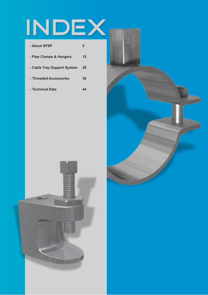
INDEX- About SFSP
- Pipe Clamps & Hangers
- Cable Tray Support System
- Threaded Accessories
- Technical Data
2
12
28
36
44

2BASKET TRAY Systems | 2

33
ABOUTSFSP

4
SFSPSpecialized Factory for Steel Products /s.a.r.l www.sfsp-lebanon.com
Specialized Factory for Steel Products is a leading factory in Lebanon, established in the year 2011 to serve the steel construction products industry in Lebanon and the region.Production at the factory is observed using modern practices of manufacturing methods in the steel construction industry with a definite compliance to international standards of fabrication.SFSP adapts quickly and easily to market demands and requirements. The factory is operating a top of the line production machinery, automated with high technology to ensure quality and maintain speed with delicacy.Quality at SFSP is uncompromised; the factory is working as per ISO 9001: 2008 Quality Management System, with care for the safety of its workers and clients as well as the welfare of its society by acknowledging the environmental key issues, trying to maintain a pollution-free production facility
TECHNICAL SERVICES
A crucial factor in the job of a factory is to provide continuous technical services and consultations.That’s why SFSP has invested in a professional team of researchers and specialists. SFSP has recruited brilliant graduates and experienced engineers having the appropriate knowhow on the on latest technology changes and development in the steel building materials industry. The product range is developed and updated according to the relevant standards of fabrication across markets, whilst the business processes are evaluated to achieve maximum efficiency.
SFSP R&D Core Objectives- Carry out responsibilities effectively in a safe and healthy work environment.- Develop and implement research programs relevant to the products and solutions introduced and ensure
that the results are communicated clearly in-house and among the clients , concisely and accurately.

5
SOCIAL RESPONSIBILITY
Being socially responsible is a part of who we are and how we do our business. We aim to provide useful products and services, to provide jobs and development opportunities for our communities, and to gain satisfaction through meaningful work. We make a difference by acting on the values and principles of our societies and we inspire others to do so. At SFSP, we anticipate and reduce threats caused by environmental changes or natural disasters, and we are well adapted to significant social changes. We contribute to a more sustainable society by means of value and support to our consumers, supply chains, and stakeholders. We are keen to identify ways they can improve our impacts on the people and places we work and live in, and thereby become more valuable and valued members of society.
- Organizational governance: We promote accountability and transparency at all levels, thus, promoting responsibility
- Human care: We treat individuals with respect; and make efforts to help members of vulnerable groups
- Labor practices: We provide just, safe and favorable conditions to workers- Environment: At SFSP, we Identify and improve environmental impacts of our operations,
including the resource use of natural resources and waste disposal.- Fair operating practices: Practicing accountability and fairness in dealings with other
businesses
At SFSP, we are committed to continuous improvement – ongoing learning, process review and innovative thinking that foster new initiatives; and better practices. Our environmental programs evolve to meet today’s changing needs
while; protecting resources for future; generations.

6
ENVIRONMENTAL AWARENESS
SFSP is committed to the following:• Compliance with all statutory and regulatory requirements related to its activities, products and
services and the environmental aspects.• Identifying quality and environmental objectives by review and audit of the processes both in-
house and on-site.• Formally setting objectives based on the results of the process reviews and their
significance in relation to their impact on the environment and the continual improvement of the quality and environmental management system.
• Implementing management programs to achieve these objectives.• Investing in a well-trained and motivated workforce.• Working closely with suppliers and customers to ensure mutual understanding and
benefits of the environmental aspects consideration.• Reviewing our policy and objectives as part of the Management Review Process.• Communicating this policy to all persons working for or on behalf of the
organization.• Preventing and minimizing Pollution to the environment.
LOCATIONSFSP / [email protected]
Specialized Factory for Steel Products / s.a.r.l Tanayel, BekaaTel: +961 8 514 290Fax: +961 8 514 291
7
HEALTH AND SAFETY
The Factory Management regard the health and safety of the employees, clients and all others that may be affected by their operations to be of a major importance.
In support of this, the management promotes health and safety throughout the Factory’s operations and endeavour to engender a positive attitude in all employees towards the prevention of accidents and maintenance of healthy working arrangements.
The Factory satisfies the requirements of the Health, Safety and related legislation by setting out the responsibilities of all levels of staff and the arrangements for carrying out those responsibilities and in particular do what is reasonably practicable to:1. Maintains safe & healthy working conditions.2. Ensures that all facilities and equipment are safe and properly maintained.3. Provides products that can be applied and used safely and without risk to health.4. Provides and maintain working procedures, that are safe and without risk to health, throughout the its
operations in respect of: • The use, handling, storage, transports and disposal of materials and substances. • The use of factory equipment. • Potential emergency situations, including first aid, fire and escape of substances.5. Ensure the competence of employees.
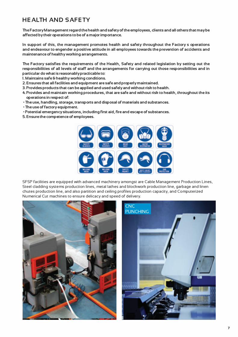
SFSP facilities are equipped with advanced machinery amongst are Cable Management Production Lines, Steel cladding systems production lines, metal lathes and blockwork production line, garbage and linen chutes production line, and also partition and ceiling profiles production capacity, and Computerized Numerical Cut machines to ensure delicacy and speed of delivery.
CNC PUNCHING

8
SFSP PRODUCTS
SFSP produces a variety of products ranging from cable management systems; cable trays, cable ladders, basket trays, trunkings and support systems, to mechanical cladding fixations, steel lintels and block work accessories, plasterers’ beads, expanded metal and block work reinforcement, strut channel systems, pipe clamps & hangers, gypsum profiles as well as garbage and linen chutes. With the introduction of new machines and the enhancement of production methods, SFSP continues to develop its production methods systematically as well as thoroughly.
CABLE TRAYS & ACCESSORIESCable Trays are designed to meet most requirements of cable and electrical wire installations and comply to local and international standards of fabrications and finishes.
CABLE LADDERS (WELDED & SWAGED)Cable Ladders of different side heights are available upon request.
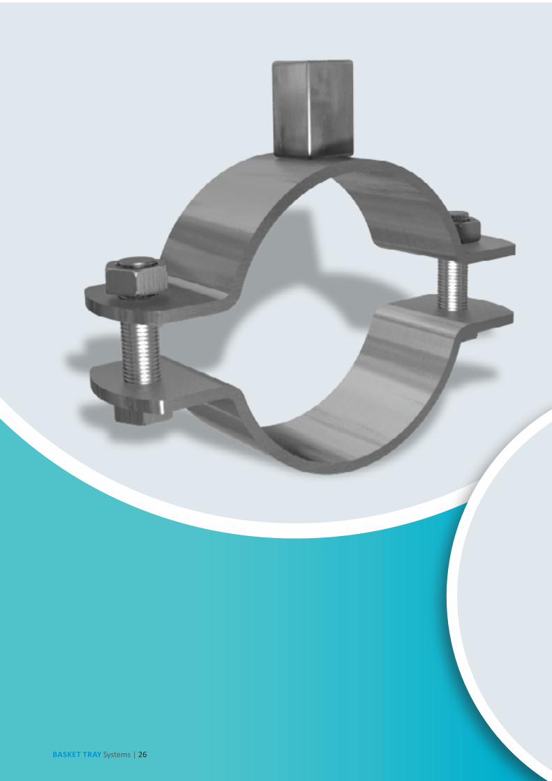
BASKET TRAYS & ACCESSORIESSFSP’s Basket Tray systems make connections fast and simple with limited need for tools. Its design allows for continuous airflow, and prevents heating up of cables. SFSP’s Basket Tray comes in a full range of sizes and is made with high-strength welded steel wires.
CABLE TRUNKINGSCable Trunkings and Accessories are offered in a comprehensive range. Mill galvanized, hot-dip galvanized, and powder coated are the various finishes produced in our factories.
UNDERFLOOR TRUNKINGUnderfloor Trunking Systems solutions incorporate a range of products for the distribution of power and data services , it is a coordinated set of containments that protect, segregate, contain, and route cables within a given environment.
CABLE MANAGEMENT SUPPORT SYSTEMSCable Support Systems are well designed to provide necessary support for cable trays, cable ladders and trunkings. Cable supports are manufactured according to common standards from high quality raw materials.
C-CHANNEL STRUT SYSTEMSSFSP’s Metal Framing Systems provide an economical solution for electrical, mechanical and industrial supports with a wide variety of applications in the construction industry.Applications: - Pipe and Conduit Supports - Tunnel Pipe Stanchions - Racks and Shelvings - Wall Framings.

9
EXPANDED METALS, PLASTERERS` BEADSExpanded Metals help the formation of joints, protection of corners and resistance against cracks, chips and impact damage.
BLOCK LADDER REINFORCEMENTSFSP ladder and truss types are used for the reinforcement of brick and block masonry to give improved tensile strength to walls subjected to lateral loading e.g. wind and seismic. SFSPblock reinforcements reduces the risk of cracking either at stress concentration around opening.
STEEL LINTELS & BLOCK WORK ACCESSORIESSteel Lintels provide a combination of strength and light weight, resulting in efficient load bearing performance and increased productivity on site. They are characterized by their ease of installation in addition to time as well as money saving.
PIPE CLAMPS & HANGERSPipe Clamps and Hangers from SFSP used in the support of pipes and equipments are manufactured according to the highest standards of fabrication.A diversified choice of Pipe Hangers, Pipe Clamps, EMT Straps, Omega Clamps, Beam Clamps, J and U-Bolts and Threaded Accessories.
MARBLE & GRANITE FIXINGSStangle Cladding Fixation includes design, calculation and production of several types of mechanical fixings and accessories used for cladding purposes. Stainless and galvanized steel are among the various materials used in the fabrication.
DRY WALL & CEILING PROFILESSFSP provides a complete product range for dry wall and ceiling constructions. Studs, Runners, Furring Channels, Ceiling Channels and Wall Angles are among the range of products produced to service the dry wall installers.
GARBAGE & LINEN CHUTESChutes from SFSP are very convenient, simple and low cost method of controlling and disposing of refuse and linen. Chutes meet the most stringent requirements of environmental health and safety. Chutes are used as original equipment in new buildings, such as : Hotels, Hospitals, High Rises and Residential Towers.
EXPANSION JOINTS COVERSSFSP manufactures architectural lines of thermal, seismic, waterproof, and fire-rated expansion joint systems meeting aesthetic and structural demands of multiple projects including airports, hospitals, commercial and residential buildings, shopping malls, and several other structural typesMaterials used in SFSP expansion joints systems includes 6063 Aluminum, Rubber (Natural and Neoprene), Stainless Steel, TPE.
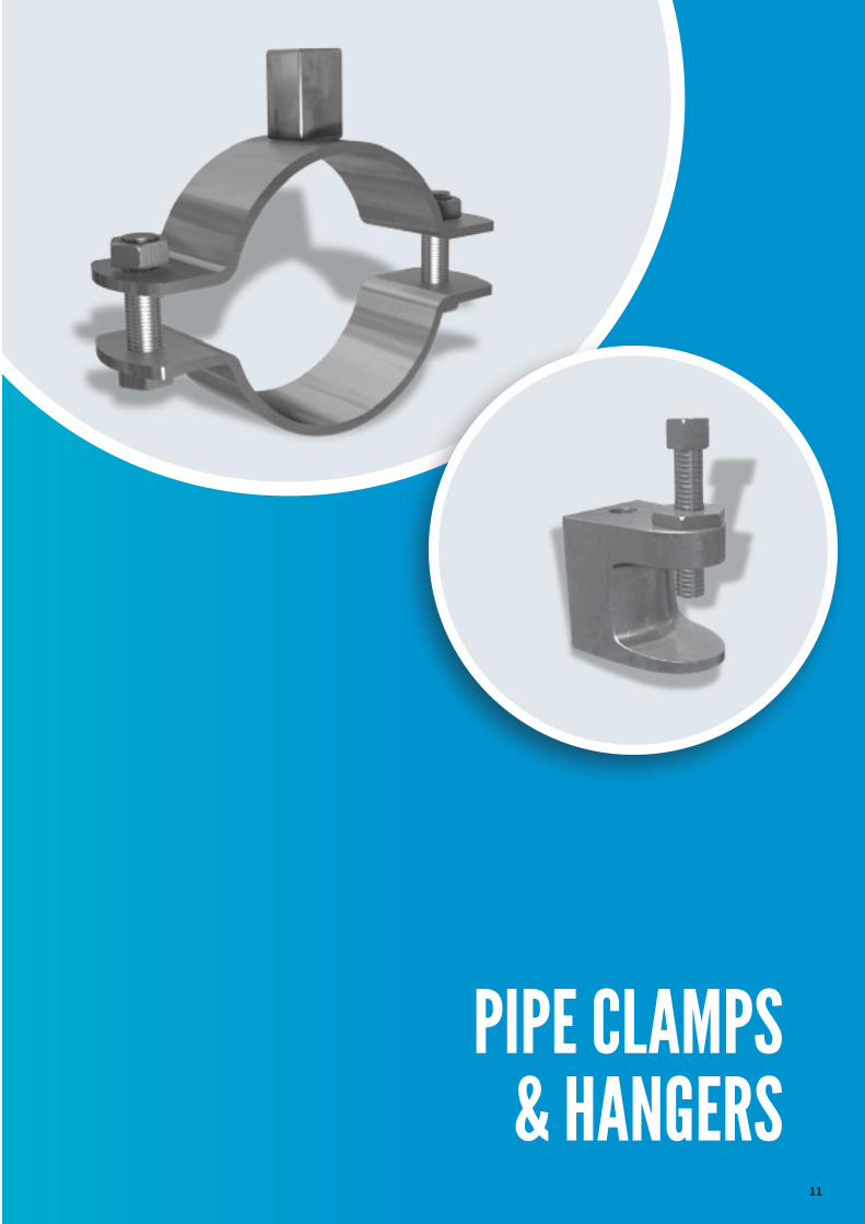
PIPE CLAMPS & HANGERS
10
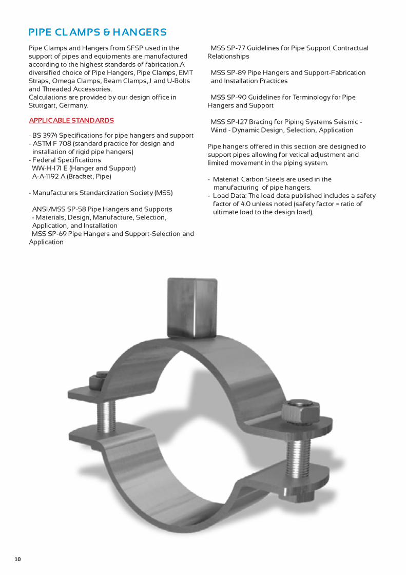
Pipe Clamps and Hangers from SFSP used in the support of pipes and equipments are manufactured according to the highest standards of fabrication.A diversified choice of Pipe Hangers, Pipe Clamps, EMT Straps, Omega Clamps, Beam Clamps, J and U-Bolts and Threaded Accessories.Calculations are provided by our design office in Stuttgart, Germany.
APPLICABLE STANDARDS
- BS 3974 Specifications for pipe hangers and support- ASTM F 708 (standard practice for design and
installation of rigid pipe hangers)- Federal Specifications WW-H-171 E (Hanger and Support) A-A-1192 A (Bracket, Pipe)
- Manufacturers Standardization Society (MSS)
ANSI/MSS SP-58 Pipe Hangers and Supports - Materials, Design, Manufacture, Selection, Application, and Installation
MSS SP-69 Pipe Hangers and Support-Selection and Application
MSS SP-77 Guidelines for Pipe Support Contractual Relationships
MSS SP-89 Pipe Hangers and Support-Fabrication and Installation Practices
MSS SP-90 Guidelines for Terminology for Pipe Hangers and Support
MSS SP-127 Bracing for Piping Systems Seismic - Wind - Dynamic Design, Selection, Application
Pipe hangers offered in this section are designed to support pipes allowing for vetical adjustment and limited movement in the piping system.
- Material: Carbon Steels are used in the manufacturing of pipe hangers.
- Load Data: The load data published includes a safety factor of 4.0 unless noted (safety factor = ratio of ultimate load to the design load).
11
PIPE CLAMPS & HANGERS

12
- Material: Steel S235- Service: Multifunction screw with hexagonal combination head (slot & crosshead), c/ w retaining
washer- Finish: Electro Zinc Plated- Applications: - Fresh water distribution pipes- Waste water distribution pipes- Gas distribution pipes- Heating pipes- Industrial pipe fitting- Mechanical installation- Process and control lines
Split Pipe Clamp with Long Nut M8/ M10 without rubber gasket
Nominal Pipe Size
Outside Diameter
Side Bolt Thickness& Width
Load Capacity
Material
In mm mm mm mm KN
1/2 15 20-25 M6x20 2.0x20 1.30 GA
3/4 20 26-30 M6x20 2.0x20 1.30 GA
1 25 32-36 M6x20 2.0x20 1.30 GA
5/4 32 38-45 M6x20 2.0x20 1.30 GA
3/2 40 47-51 M6x20 2.0x20 1.30 GA
2 50 60-64 M6x20 2.0x20 1.30 GA
5/2 65 74-80 M6x20 2.5x20 1.90 GA
3 80 87-92 M6x20 2.5x20 1.90 GA
4 100 113-118 M6x20 2.5x20 1.90 GA
5 125 138-142 M6x20 2.5x20 1.90 GA
6 150 159-166 M6x30 2.5x20 1.90 GA
1/2 15 20-25 M6x20 2.0x20 1.30 G3/4 20 26-30 M6x20 2.0x20 1.30 G1 25 32-36 M6x20 2.0x20 1.30 G
5/4 32 38-45 M6x20 2.0x20 1.30 G3/2 40 47-51 M6x20 2.0x20 1.30 G2 50 60-64 M6x20 2.0x20 1.30 G
5/2 65 74-80 M6x20 2.5x20 1.90 G3 80 87-92 M6x20 2.5x20 1.90 G4 100 113-118 M6x20 2.5x20 1.90 G5 125 138-142 M6x20 2.5x20 1.90 G6 150 159-166 M6x30 2.5x20 1.90 G
W.
T.
S.B.
M8/10
O.D. N.P.S.

13
- Material: Steel S235- Service: Economy option- Finish: Electro Zinc Plated- Applications: - Unassembled in plastic bags per 2 sets- M6 screw with cross head
Nominal Pipe Size
Outside Diameter
Side Bolt Thickness& Width
Load Capacity
Material
In mm mm mm mm KN
1/2 15 20-25 M6x20 2.0x20 1.30 GA
3/4 20 26-30 M6x20 2.0x20 1.30 GA
1 25 32-36 M6x20 2.0x20 1.30 GA
5/4 32 38-45 M6x20 2.0x20 1.30 GA
3/2 40 47-51 M6x20 2.0x20 1.30 GA
2 50 60-64 M6x20 2.0x20 1.30 GA
5/2 65 74-80 M6x20 2.5x20 1.90 GA
3 80 87-92 M6x20 2.5x20 1.90 GA
4 100 113-118 M6x20 2.5x20 1.90 GA
5 125 138-142 M6x20 2.5x20 1.90 GA
6 150 159-166 M6x20 2.5x20 1.90 GA
1/2 15 20-25 M6x20 2.0x20 1.30 G3/4 20 26-30 M6x20 2.0x20 1.30 G1 25 32-36 M6x20 2.0x20 1.30 G
5/4 32 38-45 M6x20 2.0x20 1.30 G3/2 40 47-51 M6x20 2.0x20 1.30 G2 50 60-64 M6x20 2.0x20 1.30 G
5/2 65 74-80 M6x20 2.5x20 1.90 G3 80 87-92 M6x20 2.5x20 1.90 G4 100 113-118 M6x20 2.5x20 1.90 G5 125 138-142 M6x20 2.5x20 1.90 G6 150 159-166 M6x20 2.5x20 1.90 G
Split Pipe Clamp with Standard Nut M8 without rubber gasket
W.
T.
S.B.
M8
O.D. N.P.S.
14
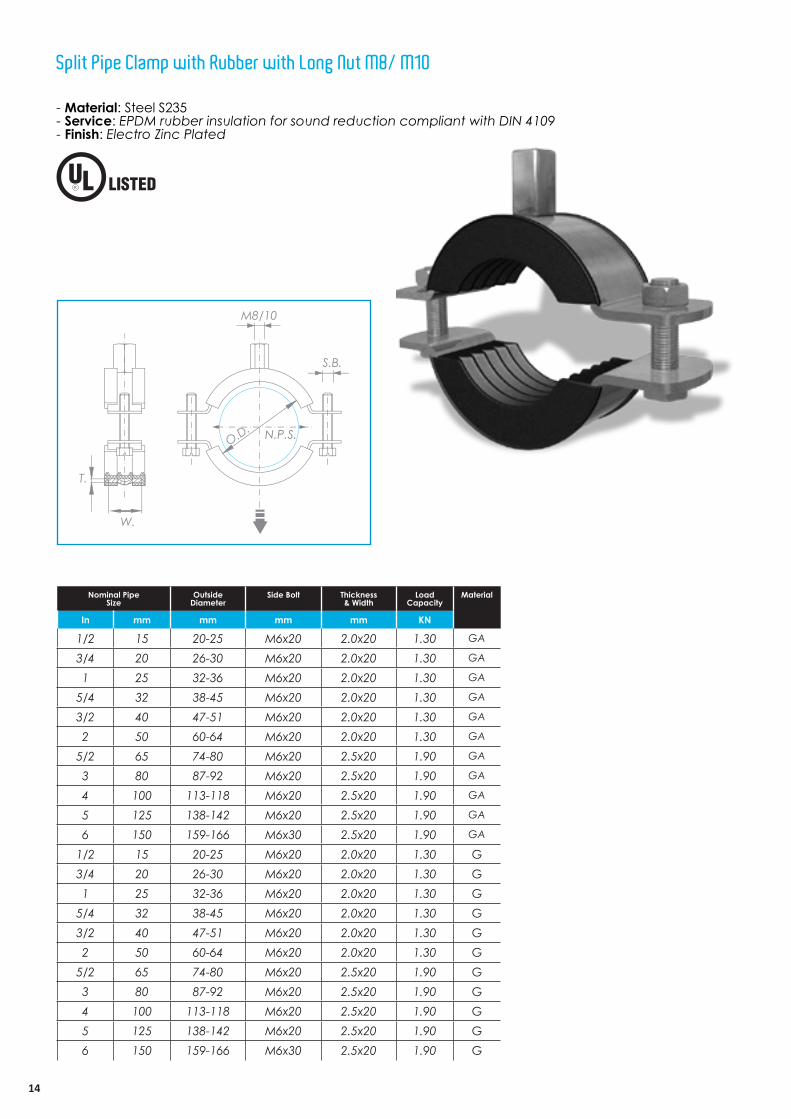
- Material: Steel S235- Service: EPDM rubber insulation for sound reduction compliant with DIN 4109- Finish: Electro Zinc Plated
Split Pipe Clamp with Rubber with Long Nut M8/ M10
Nominal Pipe Size
Outside Diameter
Side Bolt Thickness& Width
Load Capacity
Material
In mm mm mm mm KN
1/2 15 20-25 M6x20 2.0x20 1.30 GA
3/4 20 26-30 M6x20 2.0x20 1.30 GA
1 25 32-36 M6x20 2.0x20 1.30 GA
5/4 32 38-45 M6x20 2.0x20 1.30 GA
3/2 40 47-51 M6x20 2.0x20 1.30 GA
2 50 60-64 M6x20 2.0x20 1.30 GA
5/2 65 74-80 M6x20 2.5x20 1.90 GA
3 80 87-92 M6x20 2.5x20 1.90 GA
4 100 113-118 M6x20 2.5x20 1.90 GA
5 125 138-142 M6x20 2.5x20 1.90 GA
6 150 159-166 M6x30 2.5x20 1.90 GA
1/2 15 20-25 M6x20 2.0x20 1.30 G3/4 20 26-30 M6x20 2.0x20 1.30 G1 25 32-36 M6x20 2.0x20 1.30 G
5/4 32 38-45 M6x20 2.0x20 1.30 G3/2 40 47-51 M6x20 2.0x20 1.30 G2 50 60-64 M6x20 2.0x20 1.30 G
5/2 65 74-80 M6x20 2.5x20 1.90 G3 80 87-92 M6x20 2.5x20 1.90 G4 100 113-118 M6x20 2.5x20 1.90 G5 125 138-142 M6x20 2.5x20 1.90 G6 150 159-166 M6x30 2.5x20 1.90 G
W.
T.
S.B.
M8/10
O.D. N.P.S.
15
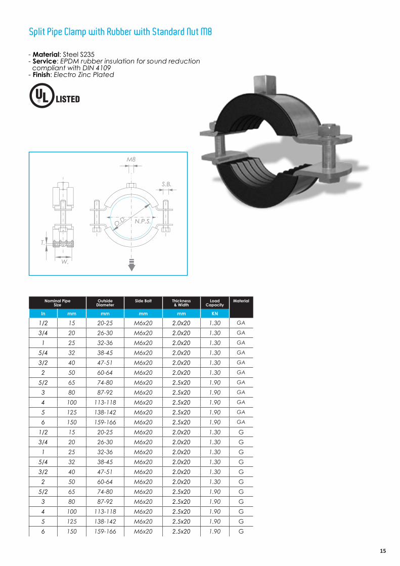
- Material: Steel S235- Service: EPDM rubber insulation for sound reduction compliant with DIN 4109- Finish: Electro Zinc Plated
Nominal Pipe Size
Outside Diameter
Side Bolt Thickness& Width
Load Capacity
Material
In mm mm mm mm KN
1/2 15 20-25 M6x20 2.0x20 1.30 GA
3/4 20 26-30 M6x20 2.0x20 1.30 GA
1 25 32-36 M6x20 2.0x20 1.30 GA
5/4 32 38-45 M6x20 2.0x20 1.30 GA
3/2 40 47-51 M6x20 2.0x20 1.30 GA
2 50 60-64 M6x20 2.0x20 1.30 GA
5/2 65 74-80 M6x20 2.5x20 1.90 GA
3 80 87-92 M6x20 2.5x20 1.90 GA
4 100 113-118 M6x20 2.5x20 1.90 GA
5 125 138-142 M6x20 2.5x20 1.90 GA
6 150 159-166 M6x20 2.5x20 1.90 GA
1/2 15 20-25 M6x20 2.0x20 1.30 G3/4 20 26-30 M6x20 2.0x20 1.30 G1 25 32-36 M6x20 2.0x20 1.30 G
5/4 32 38-45 M6x20 2.0x20 1.30 G3/2 40 47-51 M6x20 2.0x20 1.30 G2 50 60-64 M6x20 2.0x20 1.30 G
5/2 65 74-80 M6x20 2.5x20 1.90 G3 80 87-92 M6x20 2.5x20 1.90 G4 100 113-118 M6x20 2.5x20 1.90 G5 125 138-142 M6x20 2.5x20 1.90 G6 150 159-166 M6x20 2.5x20 1.90 G
Split Pipe Clamp with Rubber with Standard Nut M8
S.B.
M8
O.D.
W.
T.
N.P.S.

16
- Material: Steel S235- Service: Designed for hanging conduit (rigid or EMT) to beam clamps, available with or without closure bolt- Finish: Electro Zinc Plated
Omega Conduit & Pipe Clamp
Nominal Pipe Size
Outside Diameter
Side Bolt Thickness& Width
Load Capacity
Material
In mm mm mm mm KN
1/2 15 20-25 M6x20 2.0x20 1.30 GA
3/4 20 26-30 M6x20 2.0x20 1.30 GA
1 25 32-36 M6x20 2.0x20 1.30 GA
5/4 32 38-45 M6x20 2.0x20 1.30 GA
3/2 40 47-51 M6x20 2.0x20 1.30 GA
2 50 60-64 M6x20 2.0x20 1.30 GA
5/2 65 74-80 M6x20 2.5x20 1.90 GA
3 80 87-92 M6x20 2.5x20 1.90 GA
4 100 113-118 M6x20 2.5x20 1.90 GA
5 125 138-142 M6x20 2.5x20 1.90 GA
6 150 159-166 M6x20 2.5x20 1.90 GA
1/2 15 20-25 M6x20 2.0x20 1.30 G3/4 20 26-30 M6x20 2.0x20 1.30 G1 25 32-36 M6x20 2.0x20 1.30 G
5/4 32 38-45 M6x20 2.0x20 1.30 G3/2 40 47-51 M6x20 2.0x20 1.30 G2 50 60-64 M6x20 2.0x20 1.30 G
5/2 65 74-80 M6x20 2.5x20 1.90 G3 80 87-92 M6x20 2.5x20 1.90 G4 100 113-118 M6x20 2.5x20 1.90 G5 125 138-142 M6x20 2.5x20 1.90 G6 150 159-166 M6x20 2.5x20 1.90 G

17
Pipe Straps for thin metallic wall conduits (EMT) (Electrical Metallic Tubing)
WOD
T
- Material: Steel S235- Service: For mounting (rigid or EMT) and steel pipes on C-Channels- Finish: Electro Zinc Plated or Hot-dip Galvanized
Nominal Pipe Size
Outside DiameterEMT Rigid
Thickness& Width
Load Capacity
Material
In mm mm mm mm KN
1/2 15 20 25 1.5x28 1.30 GA
3/4 20 26 30 1.5x28 1.30 GA
1 25 32 40 2.0x28 1.30 GA
5/4 32 42 45 2.0x28 1.30 GA
3/2 40 46 50 2.5x28 1.30 GA
2 50 60 64 2.5x28 1.30 GA
5/2 65 74 80 2.5x28 1.90 GA
3 80 86 92 2.8x28 1.90 GA
4 100 112 118 3.0x28 1.90 GA
5 125 138 142 3.0x28 1.90 GA
6 150 160 165 3.0x28 1.90 GA
1/2 15 20 25 1.5x28 1.30 G3/4 20 26 30 1.5x28 1.30 G1 25 32 40 2.0x28 1.30 G
5/4 32 42 45 2.0x28 1.30 G3/2 40 46 50 2.5x28 1.30 G2 50 60 64 2.5x28 1.30 G
5/2 65 74 80 2.5x28 1.90 G3 80 86 92 2.8x28 1.90 G4 100 112 118 3.0x28 1.90 G5 125 138 142 3.0x28 1.90 G6 150 160 165 3.0x28 1.90 G
Channel Clamp
18
HOD
T
W
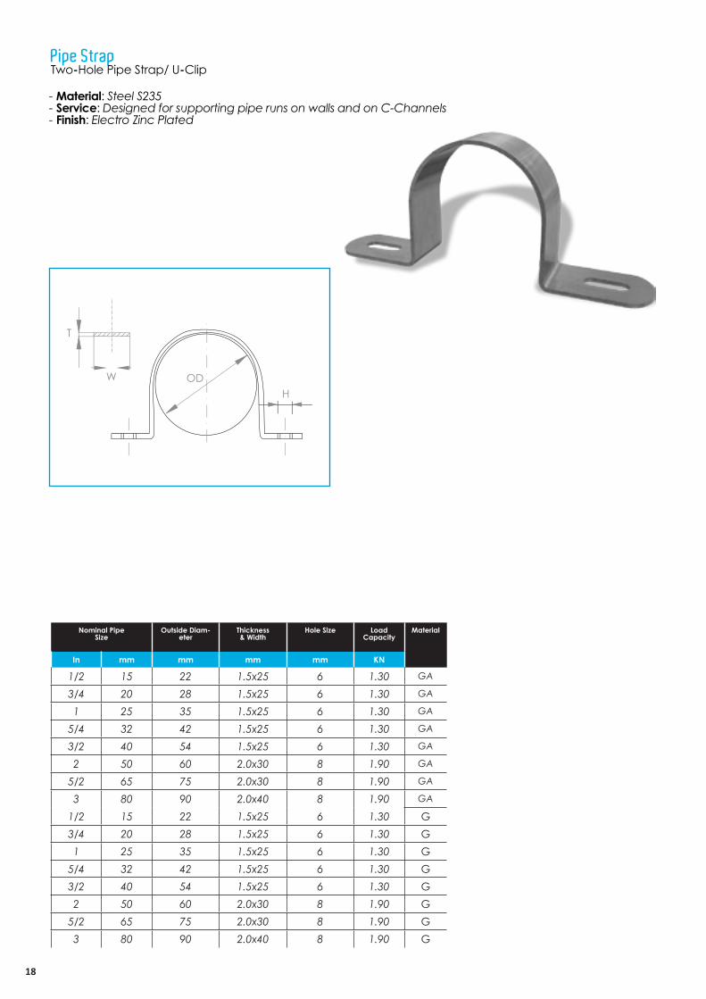
- Material: Steel S235- Service: Designed for supporting pipe runs on walls and on C-Channels- Finish: Electro Zinc Plated
Nominal Pipe Size
Outside Diam-eter
EMT Rigid
Thickness& Width
Hole Size Load Capacity
Material
In mm mm mm mm KN
1/2 15 22 1.5x25 6 1.30 GA
3/4 20 28 1.5x25 6 1.30 GA
1 25 35 1.5x25 6 1.30 GA
5/4 32 42 1.5x25 6 1.30 GA
3/2 40 54 1.5x25 6 1.30 GA
2 50 60 2.0x30 8 1.90 GA
5/2 65 75 2.0x30 8 1.90 GA
3 80 90 2.0x40 8 1.90 GA
1/2 15 22 1.5x25 6 1.30 G3/4 20 28 1.5x25 6 1.30 G1 25 35 1.5x25 6 1.30 G
5/4 32 42 1.5x25 6 1.30 G3/2 40 54 1.5x25 6 1.30 G2 50 60 2.0x30 8 1.90 G
5/2 65 75 2.0x30 8 1.90 G3 80 90 2.0x40 8 1.90 G
Pipe StrapTwo-Hole Pipe Strap/ U-Clip

19
NPS
WH
T
- Material: Steel S235- Service: Designed for supporting standard conduits, cable and steel pipes on walls or sides of beams or on C-Channels- Finish: Electro Zinc Plated Not recommended for use horizontally on ceilings, bottoms of beams and similar installations since the factor of safety is greatly reduced when so used
Nominal Pipe Size
Thickness& Width
Hole Size Load Capacity
Material
In mm mm mm KN
1/2 15 1.0x25 6 0.40 GA
3/4 20 1.0x25 6 0.40 GA
1 25 1.0x25 6 0.40 GA
5/4 32 1.5x25 6 0.40 GA
3/2 40 1.5x25 6 0.40 GA
2 50 1.5x25 8 0.40 GA
5/2 65 2.0x25 8 0.45 GA
3 80 2.5x25 8 0.45 GA
1/2 15 1.0x25 6 0.40 G3/4 20 1.0x25 6 0.40 G1 25 1.0x25 6 0.40 G
5/4 32 1.5x25 6 0.40 G3/2 40 1.5x25 6 0.40 G2 50 1.5x25 8 0.40 G
5/2 65 2.0x25 8 0.45 G3 80 2.5x25 8 0.45 G
One-Hole Pipe Strap <Snap Type>
20
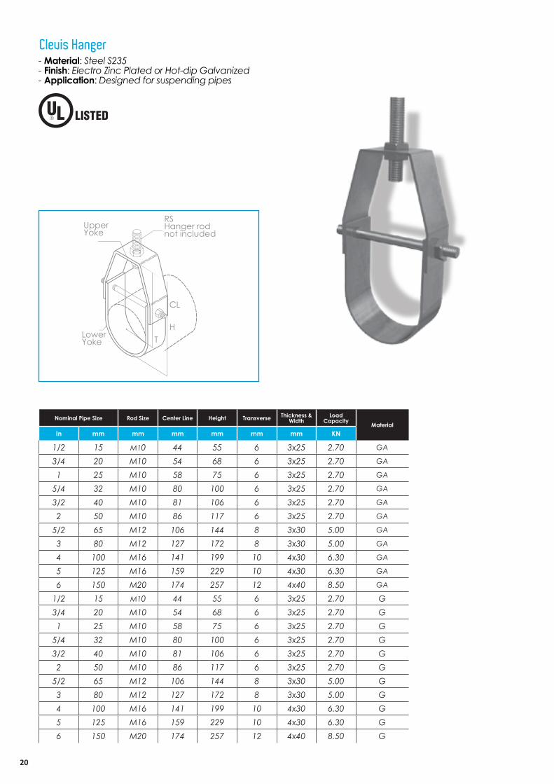
- Material: Steel S235- Finish: Electro Zinc Plated or Hot-dip Galvanized - Application: Designed for suspending pipes
Clevis Hanger
RSHanger rod not included
CL
TH
Lower Yoke
Upper Yoke
Nominal Pipe Size Rod Size Center Line Height Transverse Thickness & Width
Load Capacity
MaterialIn mm mm mm mm mm mm KN
1/2 15 M10 44 55 6 3x25 2.70 GA
3/4 20 M10 54 68 6 3x25 2.70 GA
1 25 M10 58 75 6 3x25 2.70 GA
5/4 32 M10 80 100 6 3x25 2.70 GA
3/2 40 M10 81 106 6 3x25 2.70 GA
2 50 M10 86 117 6 3x25 2.70 GA
5/2 65 M12 106 144 8 3x30 5.00 GA
3 80 M12 127 172 8 3x30 5.00 GA
4 100 M16 141 199 10 4x30 6.30 GA
5 125 M16 159 229 10 4x30 6.30 GA
6 150 M20 174 257 12 4x40 8.50 GA
1/2 15 M10 44 55 6 3x25 2.70 G3/4 20 M10 54 68 6 3x25 2.70 G1 25 M10 58 75 6 3x25 2.70 G
5/4 32 M10 80 100 6 3x25 2.70 G3/2 40 M10 81 106 6 3x25 2.70 G2 50 M10 86 117 6 3x25 2.70 G
5/2 65 M12 106 144 8 3x30 5.00 G3 80 M12 127 172 8 3x30 5.00 G4 100 M16 141 199 10 4x30 6.30 G5 125 M16 159 229 10 4x30 6.30 G6 150 M20 174 257 12 4x40 8.50 G
21
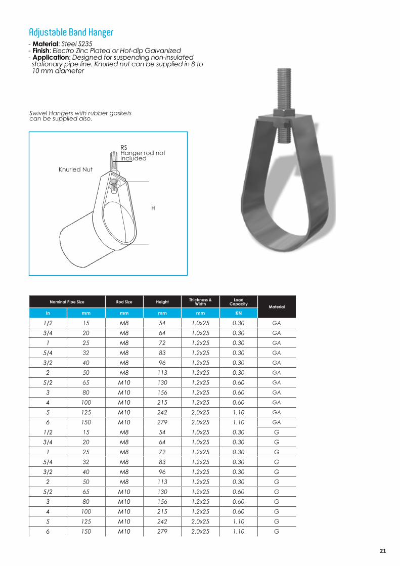
- Material: Steel S235- Finish: Electro Zinc Plated or Hot-dip Galvanized - Application: Designed for suspending non-insulated stationary pipe line. Knurled nut can be supplied in 8 to 10 mm diameter
Adjustable Band Hanger
Nominal Pipe Size Rod Size Height Thickness & Width
Load Capacity
MaterialIn mm mm mm mm KN
1/2 15 M8 54 1.0x25 0.30 GA
3/4 20 M8 64 1.0x25 0.30 GA
1 25 M8 72 1.2x25 0.30 GA
5/4 32 M8 83 1.2x25 0.30 GA
3/2 40 M8 96 1.2x25 0.30 GA
2 50 M8 113 1.2x25 0.30 GA
5/2 65 M10 130 1.2x25 0.60 GA
3 80 M10 156 1.2x25 0.60 GA
4 100 M10 215 1.2x25 0.60 GA
5 125 M10 242 2.0x25 1.10 GA
6 150 M10 279 2.0x25 1.10 GA
1/2 15 M8 54 1.0x25 0.30 G3/4 20 M8 64 1.0x25 0.30 G1 25 M8 72 1.2x25 0.30 G
5/4 32 M8 83 1.2x25 0.30 G3/2 40 M8 96 1.2x25 0.30 G2 50 M8 113 1.2x25 0.30 G
5/2 65 M10 130 1.2x25 0.60 G3 80 M10 156 1.2x25 0.60 G4 100 M10 215 1.2x25 0.60 G5 125 M10 242 2.0x25 1.10 G6 150 M10 279 2.0x25 1.10 G
Swivel Hangers with rubber gasketscan be supplied also.
H
Knurled Nut
RSHanger rod not included

22
T-W: Thickness - Width
AB
Hole
Size
TW
T W
C
- Material: Steel S235- Service: Designed for supporting and stabilizing vertical pipe runs- Finish: Electro Zinc Plated or Hot-dip Galvanized
Offset Pipe Clamp
Nominal Pipe Size A B C Hole Size Thickness & Width
Load Capacity
MaterialIn mm mm mm mm mm mm KN
1/2 15 60 8x40 150 10 3x30 0.90 GA
3/4 20 60 8x40 175 10 3x30 0.90 GA
1 25 65 8x40 190 10 3x30 0.90 GA
5/4 32 75 8x40 200 10 3x30 0.90 GA
2 50 80 10x50 225 12 4.5x30 1.20 GA
5/2 65 85 10x50 250 12 4.5x30 1.20 GA
3 80 95 10x50 275 12 4.5x30 1.20 GA
4 100 105 12x50 300 14 5x40 1.80 GA
6 150 130 12x50 400 14 5x40 1.80 GA
8 200 160 12x50 450 14 5x40 1.80 GA
1/2 15 60 8x40 150 10 3x30 0.90 G3/4 20 60 8x40 175 10 3x30 0.90 G1 25 65 8x40 190 10 3x30 0.90 G
5/4 32 75 8x40 200 10 3x30 0.90 G2 50 80 10x50 225 12 4.5x30 1.20 G
5/2 65 85 10x50 250 12 4.5x30 1.20 G3 80 95 10x50 275 12 4.5x30 1.20 G4 100 105 12x50 300 14 5x40 1.80 G6 150 130 12x50 400 14 5x40 1.80 G8 200 160 12x50 450 14 5x40 1.80 G

23
- Material: EPDM. Rubber- Load Data: At normal frequency and pressure range, noise suppression 20 dB(A) & the temperature-resistant from-40 °C to + 100 °C- Electrical values: Specific resistance: 2x10⁹ M ohm cm2 & the Surface resistance: 2 x10⁹ M ohm
Noise Suppression ProfileSR noise-suppression strip for insertion in clamps and hangers
Rubber DIN 4109
BC
A
Dimension
MaterialSize A B C
Codes mm mm mm mm
20x6 6 3 20 GA
20x6 6 3 20 G
24
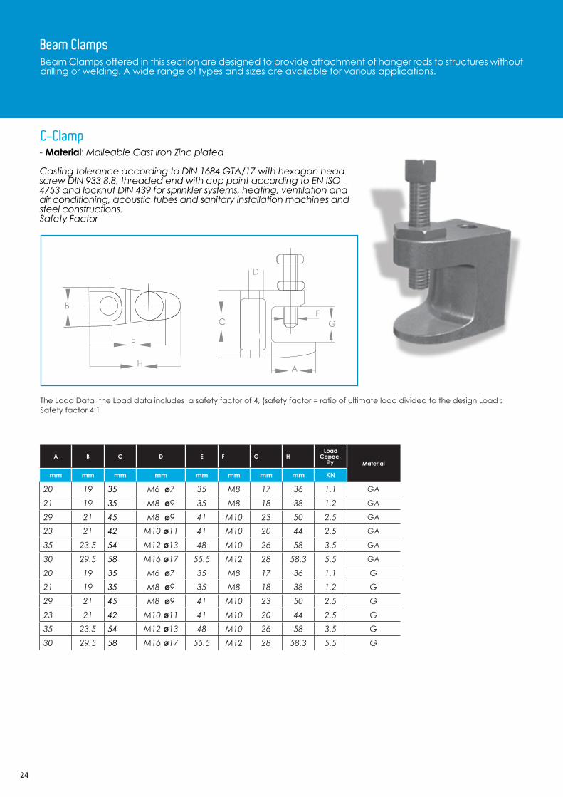
Beam Clamps offered in this section are designed to provide attachment of hanger rods to structures without drilling or welding. A wide range of types and sizes are available for various applications.
Beam Clamps
A
F
D
GC
B
E
H
The Load Data the Load data includes a safety factor of 4, (safety factor = ratio of ultimate load divided to the design Load : Safety factor 4:1
- Material: Malleable Cast Iron Zinc plated
Casting tolerance according to DIN 1684 GTA/17 with hexagon head screw DIN 933 8.8, threaded end with cup point according to EN ISO 4753 and locknut DIN 439 for sprinkler systems, heating, ventilation and air conditioning, acoustic tubes and sanitary installation machines and steel constructions.Safety Factor
C-Clamp
A B C D E F G HLoad
Capac-ity Material
mm mm mm mm mm mm mm mm KN
20 19 35 M6 ø7 35 M8 17 36 1.1 GA
21 19 35 M8 ø9 35 M8 18 38 1.2 GA
29 21 45 M8 ø9 41 M10 23 50 2.5 GA
23 21 42 M10 ø11 41 M10 20 44 2.5 GA
35 23.5 54 M12 ø13 48 M10 26 58 3.5 GA
30 29.5 58 M16 ø17 55.5 M12 28 58.3 5.5 GA
20 19 35 M6 ø7 35 M8 17 36 1.1 G21 19 35 M8 ø9 35 M8 18 38 1.2 G29 21 45 M8 ø9 41 M10 23 50 2.5 G23 21 42 M10 ø11 41 M10 20 44 2.5 G35 23.5 54 M12 ø13 48 M10 26 58 3.5 G30 29.5 58 M16 ø17 55.5 M12 28 58.3 5.5 G
25
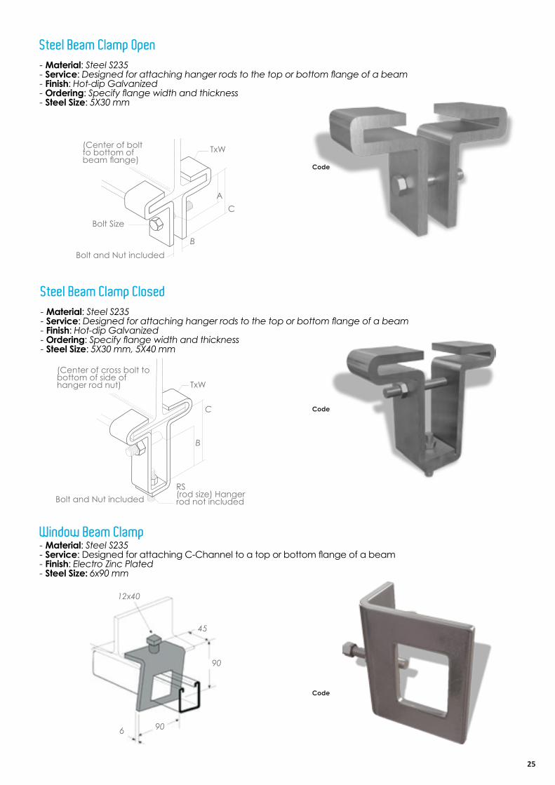
- Material: Steel S235- Service: Designed for attaching hanger rods to the top or bottom flange of a beam- Finish: Hot-dip Galvanized- Ordering: Specify flange width and thickness- Steel Size: 5X30 mm
Steel Beam Clamp Open
TxW
Bolt Size
Bolt and Nut included
(Center of bolt to bottom of beam flange)
AC
B
- Material: Steel S235- Service: Designed for attaching hanger rods to the top or bottom flange of a beam- Finish: Hot-dip Galvanized- Ordering: Specify flange width and thickness- Steel Size: 5X30 mm, 5X40 mm
- Material: Steel S235- Service: Designed for attaching C-Channel to a top or bottom flange of a beam- Finish: Electro Zinc Plated- Steel Size: 6x90 mm
Steel Beam Clamp Closed
Window Beam Clamp
TxW
B
Bolt and Nut includedRS(rod size) Hanger rod not included
(Center of cross bolt to bottom of side ofhanger rod nut)
C
12x40
45
6 90
90
Code
Code
Code
26BASKET TRAY Systems | 26

2727
CABLE TRAYSUPPORT SYSTEM
28
Z
Z
YY
Z
Z
YY
Z
Z
YY
Z
Z
Y Y
21.0
7.0
41.0
21.0
41.0
22.0
42.0
7.0
41.0
22.0
41.0
7.0
41.0
41.0
41.0
22.0
82.0
7.0
41.0
22.0
50
30
13
Z
Z
YY
Z
Z
YY
Z
Z
YY
Z
Z
Y Y
21.0
7.0
41.0
21.0
41.0
22.0
42.0
7.0
41.0
22.0
41.0
7.0
41.0
41.0
41.0
22.0
82.0
7.0
41.0
22.0
50
30
13
Z
Z
YY
Z
Z
YY
Z
Z
YY
Z
Z
Y Y
21.0
7.0
41.0
21.0
41.0
22.0
42.0
7.0
41.0
22.0
41.0
7.0
41.0
41.0
41.0
22.0
82.0
7.0
41.0
22.0
50
30
13
Z
Z
YY
Z
Z
YY
Z
Z
YY
Z
Z
Y Y
21.0
7.0
41.0
21.0
41.0
22.0
42.0
7.0
41.0
22.0
41.0
7.0
41.0
41.0
41.0
22.0
82.0
7.0
41.0
22.0
50
30
13
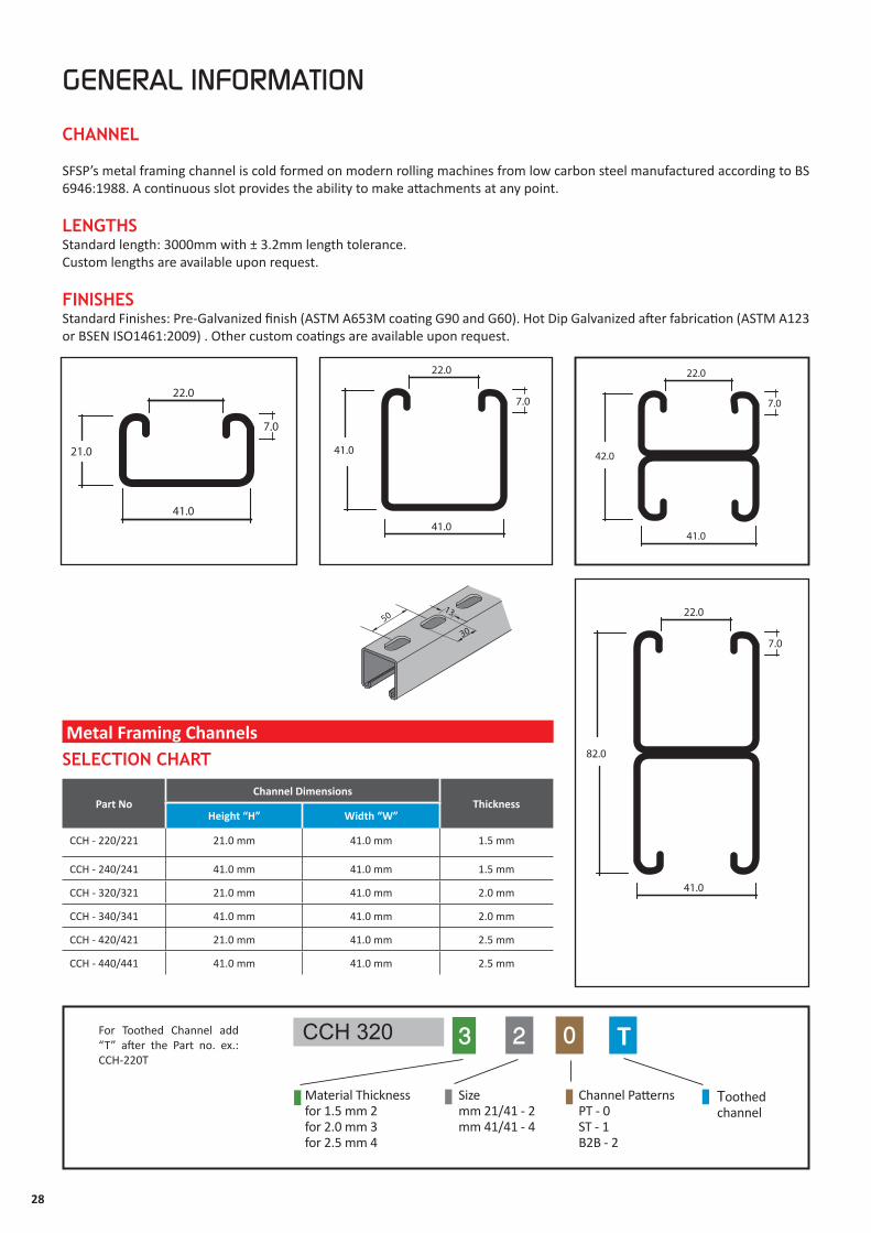
Part NoChannel Dimensions
ThicknessHeight “H” Width “W”
CCH - 220/221 21.0 mm 41.0 mm 1.5 mm
CCH - 240/241 41.0 mm 41.0 mm 1.5 mm
CCH - 320/321 21.0 mm 41.0 mm 2.0 mm
CCH - 340/341 41.0 mm 41.0 mm 2.0 mm
CCH - 420/421 21.0 mm 41.0 mm 2.5 mm
CCH - 440/441 41.0 mm 41.0 mm 2.5 mm
Toothedchannel
CCH 320 3 2 0
Channel Patterns PT - 0ST - 1B2B - 2
Size mm 21/41 - 2mm 41/41 - 4
Material Thicknessfor 1.5 mm 2
for 2.0 mm 3 for 2.5 mm 4
TFor Toothed Channel add “T” after the Part no. ex.: CCH-220T
Metal Framing Channels
GENERAL INFORMATION
CHANNEL
SFSP’s metal framing channel is cold formed on modern rolling machines from low carbon steel manufactured according to BS 6946:1988. A continuous slot provides the ability to make attachments at any point.
LENGTHSStandard length: 3000mm with ± 3.2mm length tolerance.Custom lengths are available upon request.
FINISHESStandard Finishes: Pre-Galvanized finish (ASTM A653M coating G90 and G60). Hot Dip Galvanized after fabrication (ASTM A123 or BSEN ISO1461:2009) . Other custom coatings are available upon request.
SELECTION CHART

29
ST SLOTTED TYPE B2B TYPE
Channel Hole Patterns
PT PLAIN TYPE

30
CANTILEVER ARM BRACKET
F1
1/2 A 1/2 A
or F2
Length A (mm)
h
2525
h-50
b t
Base plate : height (h) x width (b) x thickness (t) 100 50 8 •In the case of concrete support frame, use anchor M10•In the case of concrete C-Channel frame, Hex bolt M8 .** Connection force (pull-out force) : 3.10 (kN)
Base plate : height (h) x width (b) x thickness (t) 140 50 10 •In the case of concrete support frame, use anchor M16 .•In the case of concrete C-Channel frame, Hex bolt M8.** Connection force (pull-out force) : 7.50 (kN)
Cantilever Arm Brackets - SCA
Length Allowable Load
A (mm) F1* F2* Fz**
150 1.10 0.60 3.10
300 0.60 0.30 3.10
450 0.40 0.20 3.10
600 0.30 0.10 3.10
700 0.20 0.10 3.10
800 0.20 0.10 3.10
900 0.20 0.10 3.10
1000 0.20 0.10 3.10
Length Allowable Load
A (mm) F1* F2* Fz**
150 3.10 1.50 7.50
300 1.50 0.80 7.50
450 1.00 0.50 7.50
600 0.80 0.40 7.50
700 0.70 0.30 7.50
800 0.60 0.30 7.50
900 0.50 0.30 7.50
1000 0.50 0.20 7.50
* Given Loads are always in [kN] “ Allowable characteristic live load “
CCH421 41x21x2.5
A
A

31
Base plate : height (h) x width (b) x thickness (t) 140 50 10
•In the case of concrete support frame, use anchor M12.•In the case of concrete C-Channel frame, Hexbolt M8. ** Connection force (pull-out force) : 4,8 (kN)
Base plate : height (h) x width (b) x thickness (t) 180 60 12 •In the case of concrete support frame, use anchor M16.•In the case of concrete C-Channel frame, Hex bolt M10 .** Connection force (pull-out force) : 8,30 (kN)
Cantilever Arm Brackets - SCA
Length Allowable Load
A (mm) F1* F2* Fz**
150 2.50 1.30 4.80
300 1.30 0.60 4.80
450 0.80 0.40 4.80
600 0.60 0.30 4.80
700 0.50 0.30 4.80
800 0.50 0.20 4.80
900 0.40 0.20 4.80
1000 0.40 0.20 4.80
Length Allowable Load
A (mm) F1* F2* Fz**
150 7.00 3.50 8.30
300 3.50 1.80 8.30
450 2.30 1.20 8.30
600 1.80 0.90 8.30
700 1.50 0.80 8.30
800 1.30 0.70 8.30
900 1.20 0.60 8.30
1000 1.10 0.50 8.30
F1
1/2 A 1/2 A
or F2
Length A (mm)
h
b t
2525
h-50
* Given Loads are always in [kN] “ Allowable characteristic live load “
CCH422 41x21x2.5 B2B
CCH442 41x41x2.5 B2B
A
A
32
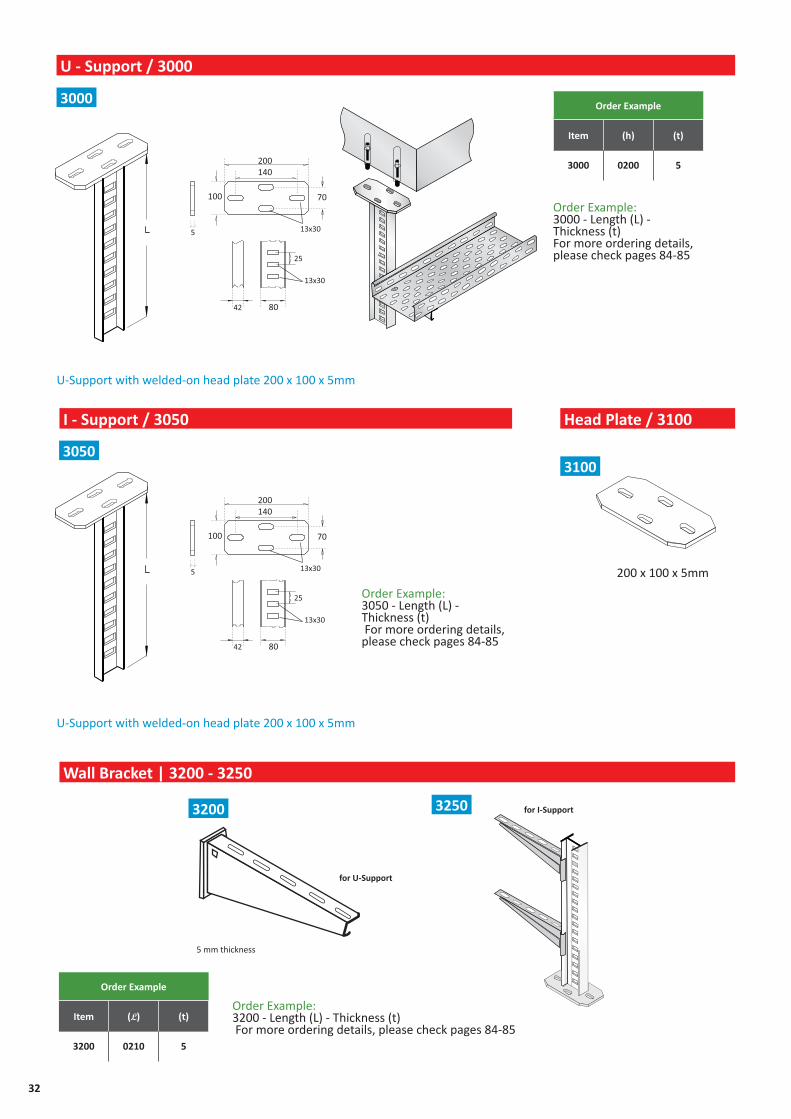
U - Support / 3000
I - Support / 3050
Wall Bracket | 3200 - 3250
Head Plate / 3100
Order Example
Item (h) (t)
3000 0200 5
Order Example
Item (L) (t)
3200 0210 5
U-Support with welded-on head plate 200 x 100 x 5mm
U-Support with welded-on head plate 200 x 100 x 5mm
3000
3050
Order Example: 3000 - Length (L) - Thickness (t) For more ordering details, please check pages 84-85
Order Example: 3050 - Length (L) - Thickness (t) For more ordering details, please check pages 84-85
200 x 100 x 5mm
3100
3200 3250
5 mm thickness
for U-Support
for I-Support
Order Example: 3200 - Length (L) - Thickness (t) For more ordering details, please check pages 84-85

33
Support connectors | 3300 Clamping plates | 3350
Support plates | 3400 Support clamps | 3450 Clamping angles | 3550
Angles | 3600
Order Example
Item (L) (t)
3300 0200 5
Order Example
Item (L) (t)
3350 0200 5
3300
3400 3450 3550
3600
3350
Order Example: 3300 - Length (L) - Thickness (t) For more ordering details, please check pages 84-85
Order Example: 3350 - Length (L) - Thickness (t) For more ordering details, please check pages 84-85

34BASKET TRAY Systems | 34

3535
- Material: For maximum loading design, carbon steel is used in the manufacturing of threaded accessories. Stainless steel and other material are available.
- Finish: Standard finishes are plain steel and Electro Plated zinc (ASTM B633 SCI) (BS 1706)
- Load Data: The load data published includes a safety of 5.0 unless noted (safety factor = ratio of ultimate load to the design load) .
Accessories offered in this section are designed to reduce installation time.
THREADED ACCESSORIES
36
Radius Size
Length
Specify L
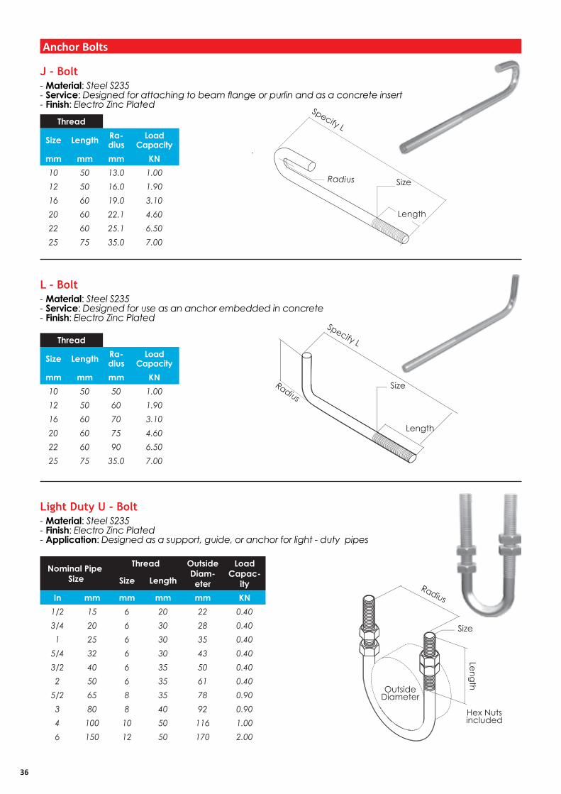
- Material: Steel S235- Service: Designed for attaching to beam flange or purlin and as a concrete insert- Finish: Electro Zinc Plated
- Material: Steel S235- Service: Designed for use as an anchor embedded in concrete- Finish: Electro Zinc Plated
- Material: Steel S235- Finish: Electro Zinc Plated - Application: Designed as a support, guide, or anchor for light - duty pipes
J - Bolt
L - Bolt
Light Duty U - Bolt
Anchor Bolts
RadiusSize
Length
Specify L
OutsideDiameter
Size
Length
Hex Nuts included
Radius
Thread
Size Length Ra-dius
Load Capacity
mm mm mm KN10 50 13.0 1.0012 50 16.0 1.9016 60 19.0 3.1020 60 22.1 4.6022 60 25.1 6.5025 75 35.0 7.00
Thread
Size Length Ra-dius
Load Capacity
mm mm mm KN10 50 50 1.0012 50 60 1.9016 60 70 3.1020 60 75 4.6022 60 90 6.5025 75 35.0 7.00
Nominal Pipe Size
Thread OutsideDiam-eter
Load Capac-
itySize Length
In mm mm mm mm KN1/2 15 6 20 22 0.403/4 20 6 30 28 0.401 25 6 30 35 0.40
5/4 32 6 30 43 0.403/2 40 6 35 50 0.402 50 6 35 61 0.40
5/2 65 8 35 78 0.903 80 8 40 92 0.904 100 10 50 116 1.006 150 12 50 170 2.00

37
Size
Eye ID
Length
Specify L
- Material: Steel S235- Finish: Electro Zinc Plated
- Material: Steel S235- Finish: Electro Zinc Plated - Application: Designed for use in hanger supports to eliminate possible bending of threaded rod
Turnbuckle
Buckle
Eye Rod
- Available in Zinc Plated Thread & Stainless Steel Thread
Rod SizeHanger Rod not included
6 ’’(152.4)
3’’ (76.2)Rod
Take Out
ThreadEye Load
CapacitySize Lengthmm mm mm KN
6 40 8 0.508 40 10 0.80
10 50 12 1.0012 50 16 2.0016 50 20 3.1020 75 22 4.7022 90 25 6.5025 100 28 8.6028 115 30 10.8030 130 34 14.00
Rod Sizemm
68
10121620222525252525
38
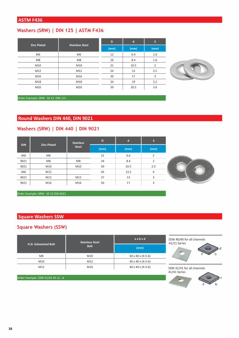
Washers (SRW) | DIN 125 | ASTM F436
Washers (SRW) | DIN 440 | DIN 9021
Square Washers (SSW)
Zinc Plated Stainless SteelD d S
(mm) (mm) (mm)
M6 M6 12 6.4 1.6
M8 M8 16 8.4 1.6
M10 M10 21 10.5 2
M12 M12 24 13 2.5
M16 M16 30 17 3
M18 M18 34 19 3.2
M20 M20 39 20.5 3.6
Order Example: SRW - M 12 -DIN 115
ASTM F436
Round Washers DIN 440, DIN 9021
Square Washers SSW
DIN Zinc Plated Stainless
Steel
D d S
(mm) (mm) (mm)
440 M6 22 6.6 2
9021 M8 M8 24 8.4 2
9021 M10 M10 30 10.5 2.5
440 M12 45 13.5 4
9021 M12 M12 37 13 3
9021 M16 M16 50 17 3
Order Example: SRW - M 12 DIN 9021
H.D. Galvanized BoltStainless Steel
Bolt
a x b x d
(mm)
M8 M10 40 x 40 x (4-5-6)
M10 M12 40 x 40 x (4-5-6)
M12 M16 40 x 40 x (4-5-6)
Order Example: SSW 41/41 M 12 - d
SSW 40/40 for all channels 41/21 Series
SSW 41/41 for all channels41/41 Series

39
Round Head (SRH) | DIN 7985
Coupler Sleeves (SCS)
Fully Threaded Rods Grade 4.6 DIN 975 ASTM A 36, A193
Round Head Machine Screws
Coupler Sleeves Rounded
Zinc Plated Thread Length Load cap.
(mm) (kN)
M6 2000/3000 2.2
M8 2000/3000 4.0
M10 2000/3000 6.4
M12 2000/3000 12.9
M16 2000/3000 17.3
M18 2000 22.0
M20 2000 27.0
Threaded Rod (STR) - DIN 975 - ASTM A36
Zinc Plated Thread
Length d
(mm) (mm)
M6 30-40 6.0
M8 30-40 8.0
M10 20-60 10.0
SRH - M10 DIN 7985
Electro-plated Thread
Stainless Steel Thread
D LLoad
Capacity
(mm) (mm) (kN)
M6 M6 10/10 15 2.2
M8 M8 12/14 20 4.0
M10 M10 13/16 25 6.4
M12 M12 16/20 30 9.3
M16 M16 21/25 40 17.3
M20 M20 26/32 50 27.0
SCS - M16
40
FRAMING SYSTEMS
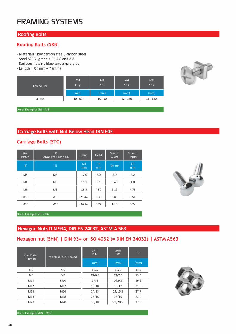
Zinc Plated Thread
Stainless Steel Thread
S/mDIN
S/mISO
e
(mm) (mm) (mm)
M6 M6 10/5 10/6 11.5
M8 M8 13/6.5 13/7.5 15.0
M10 M10 17/8 16/9.5 19.6
M12 M12 19/10 18/12 21.9
M16 M16 24/13 24/15.5 27.7
M18 M18 26/16 26/16 22.0
M20 M20 30/18 29/20.5 27.0
Order Example: SHN - M12
Zinc Plated
H.D. Galvanized Grade 4.6
Head HeadSquare Width
Square Depth
(E) (E)(A) mm
(H) mm
(O) mm(P)
mm
M5 M5 12.0 3.0 5.0 3.2
M6 M6 15.1 3.70 6.40 4.0
M8 M8 18.3 4.50 8.23 4.75
M10 M10 21.44 5.30 9.86 5.56
M16 M16 34.14 8.74 16.3 8.74
Order Example: STC - M6
Roofing Bolts (SRB)
Carriage Bolts (STC)
Hexagon nut (SHN) | DIN 934 or ISO 4032 (= DIN EN 24032) | ASTM A563
Roofing Bolts
Carriage Bolts with Nut Below Head DIN 603
Hexagon Nuts DIN 934, DIN EN 24032, ASTM A 563
Thread Size
M4
x - y M5x - y
M6x - y
M8x - y
(mm) (mm) (mm) (mm)
Length 10 - 50 10 - 80 12 - 120 16 - 150
Order Example: SRB - M6
- Materials : low carbon steel , carbon steel - Steel S235 , grade 4.6 , 4.8 and 8.8- Surfaces : plain , black and zinc plated - Length = X (mm) – Y (mm)

41
FRAMING SYSTEMS
Hexagonal Rod Coupler with view hole (SHR)
Hex Head Bolt (SHB) | DIN 933 or EN 24017 ASTM A307, A449 (without nut)
Hexagonal Rod Coupler Grade 8.8 ASTM a 563
DIN 933, DIN 24017, ASTM A307, A449
Electroplated Thread Stainless Steel Thread
D LLoad
capacity
(mm) (mm) (kN)
M10 M10 13 40 6.4
M12 M12 17 40 9.3
M16 M16 22 50 17.3
M 18 M 18 23 60 22.0
M 20 M 20 25 70 27.0
Order Example: HRC - GV - M 12
Zinc Plated Dimen-sion
Stainless Steel Dimension
S DIN S EN
(mm) (mm)
M 6 x 1210 10
M 6 x 25
M 8 x 25 M 8 x 2513 13
M 8 x 40
M 10 x 20
17 16
M 10 x 30 M 10 x 30
M 10 x 45 M 10 x 45
M 10 x 60
M 10 x 70
M 12 x 22
19 18
M 12 x 25 M 12 x 25
M 12 x 30 M 12 x 30
M 12 x 40 M 12 x 40
M 12 x 50
M 12 x 60 M 12 x 60
M 12 x 80 M 12 x 80
M 12 x 90
M 16 x 40 M 16 x 40
24 24M 16 x 60 M 16 x 60
M 16 x 90 M 16 x 90
M 18 x 40 M 18 x 40
27 26M 18 x 50 M 18 x 50
M 18 x 60 M 18 x 60
M 18 x 80 M 18 x 80
M 20 x 40 M 20 x 40
32 32M 20 x 50 M 20 x 50
M 20 x 60 M 20 x 60
M 20 x 80 M 20 x 80

42

4343
TECHNICALDATA

44
Rigid Steel Conduit (Heavy Wall Conduit)
Conduit plus weight of heaviest conductor combination as speci-fied by the National Electrical Code. Rigid and Intermediate Metal Conduit shall be supported at least every 10 feet (3.05m) and within 3 feet (914mm) of each outlet box, junction box, cabinet, or fitting. Except for straight runs of conduit connected with couplings which may be supported in accordance with NEC Article 345 and 346, provided such supports prevent transmission of stresses to termina-tion where conduit is deflected between supports.
Intermediate Metal Conduit (IMC)
Nominal Conduit Size Outside Diameter Nominal Inside DiameterMinimum Weightwith Couplings
AttachedIn mm In mm In mm Lbs/100 Ft. Kg/10 m
3/8 10 0.67 17.1 0.49 12.5 51.5 7.81/2 15 0.84 21.3 0.63 16.0 79.0 11.63/4 20 1.05 26.7 0.83 21.3 105.0 15.81 25 1.31 33.4 1.06 27.0 153.0 23.1
5/4 32 1.66 42.2 1.39 35.4 201.0 30.43/2 40 1.90 48.3 1.62 41.3 249.0 37.62 50 2.37 60.3 2.08 52.9 332.0 50.2
5/2 65 2.87 73.0 2.48 63.2 527.0 79.73 80 3.50 88.9 3.09 78.5 682.6 103.2
7/2 90 4.00 101.6 3.57 90.7 831.0 125.64 100 4.50 114.3 4.05 102.9 972.3 147.05 125 5.56 141.3 5.07 128.9 1313.6 198.66 150 6.62 168.3 6.09 154.8 1745.3 263.9
Nominal Conduit Size Outside Diameter Nominal Inside DiameterMinimum Weightwith Couplings
AttachedIn mm In mm In mm Lbs/100 Ft. Kg/10 m
1/2 15 0.81 20.7 0.74 18.9 60.0 0.73/4 20 1.02 26.1 0.95 24.2 82.0 12.41 25 1.29 32.7 1.20 30.6 116.0 17.5
5/4 32 1.63 41.6 1.55 38.9 150.0 22.63/2 40 1.88 47.8 1.79 45.5 182.0 27.32 50 2.36 59.9 2.26 57.5 242.0 36.5
5/2 65 2.85 72.5 2.72 69.2 401.0 60.63 80 3.47 88.3 3.34 85.0 493.0 74.5
7/2 90 3.97 100.8 3.84 97.5 573.0 86.64 100 4.46 113.4 4.33 110.1 638.0 96.4
Conduit Size Maximum Support SpanIn mm Feet Meters1 25 12 3.60
5/4 - 3/2 32 - 40 14 4.30 2 - 5/2 50 - 65 16 4.90 3 - 6 80 -150 20 6.00

45
Pipe Comparison Data
Electrical Metallic Tubing (EMT)Thinwall ConduitConduit plus weight of heaviest conductor combination as specified by the National Electrical Code. Electrical Metallic tubing shall be supported at least every 10 feet and within 3 feet (914mm) of each outlet box, junction box, cabinet, or fitting. See NEC Article 348.
Dim
ensio
ns ta
ken
from
AN
SI C
80.3
-197
7
Nominal Pipe Size Outside DiameterIn mm DIN(mm) ISO(mm)
3/8 10 14 17.21/2 15 20 21.33/4 20 25 26.91 25 30 33.7
5/4 32 38 42.43/2 40 44.5 48.3 2 50 57 60.3
5/2 65 76.1 76.13 80 88.9 88.9
7/2 90 101.6 101.64 100 108 114.35 125 133 139.76 150 159 168.38 200 216 219.1
10 250 267 273.012 300 318 323.914 350 368 355.616 400 419 406.418 450 459 457.220 500 521 508.024 600 622 609.628 700 720 711.232 800 820 812.836 900 920 94.440 1000 1020 1016.0
Nominal Conduit Size Outside Diameter Nominal Inside DiameterMinimum Weightwith Couplings
AttachedIn mm In mm In mm Lbs/100 Ft. Kg/10m
3/8 10 0.57 14.7 0.49 12.5 23.0 3.4
1/2 15 0.70 17.9 0.62 15.8 28.5 4.3
3/4 20 0.92 23.4 0.82 20.9 43.5 6.5
1 25 1.16 29.5 1.04 26.6 64.0 9.6
5/4 32 1.51 38.3 1.38 35.1 95.0 14.3
3/2 40 1.74 44.2 1.61 40.9 110.0 16.6
2 50 2.19 55.8 2.06 52.5 140.0 21.1
5/2 65 2.87 73.0 2.73 69.4 205.0 31.0
3 80 3.50 88.9 3.35 85.2 250.0 37.8
7/2 90 4.00 101.6 3.83 97.4 325.0 49.1
4 100 4.50 114.3 4.33 110.1 370.0 55.9

46
Rigid Aluminum ConduitD
imen
sions
take
n fro
m A
NSI
C80
.5-1
977.
Nominal Conduit Size Outside Diameter Nominal Inside DiameterMinimum Weightwith Couplings
AttachedIn mm In mm In mm Lbs/100 Ft. Kg/10m
1/2 15 0.84 21.3 0.63 16.1 27.4 5.3
3/4 20 1.05 26.7 0.83 21.2 36.4 12.4
1 25 1.31 33.4 1.06 27.0 53.0 17.5
5/4 32 1.66 42.2 1.39 35.4 69.6 22.6
3/2 40 1.90 48.3 1.62 41.2 82.2 27.5
2 50 2.37 60.3 2.08 52.9 115.7 36.5
5/2 65 2.87 73.0 2.48 63.2 182.5 60.6
3 80 3.50 88.9 3.09 78.5 238.9 74.5
7/2 90 4.00 101.6 3.57 90.7 287.7 86.6
4 100 4.50 114.3 4.05 102.9 340.0 51.4
5 125 5.56 141.3 5.07 128.9 465.4 70.3
6 150 6.62 168.3 6.09 154.8 612.5 92.6
Conduit plus weight of heaviest conductor combination as specified by the National Electrical Code. Aluminum Rigid Conduit shall be supported at least every 10 feet (3.05m) and within 3 feet (914mm) of each outlet box, junction box, cabinet, or fitting. Except for straight runs of conduit connected with couplings which may be supported in accordance with NEC Table 346-12, provided such supports prevent transmission of stresses to termination where conduit is deflected between supports.
Conduit Size Maximum Support SpanIn mm Feet Meters
1/2 - 3/4 15 - 20 10 3.00 1 25 12 3.60
5/4 - 3/2 32 - 40 14 4.30 2 - 5/2 50 - 65 16 4.90 3 - 6 80 -150 20 6.00
47
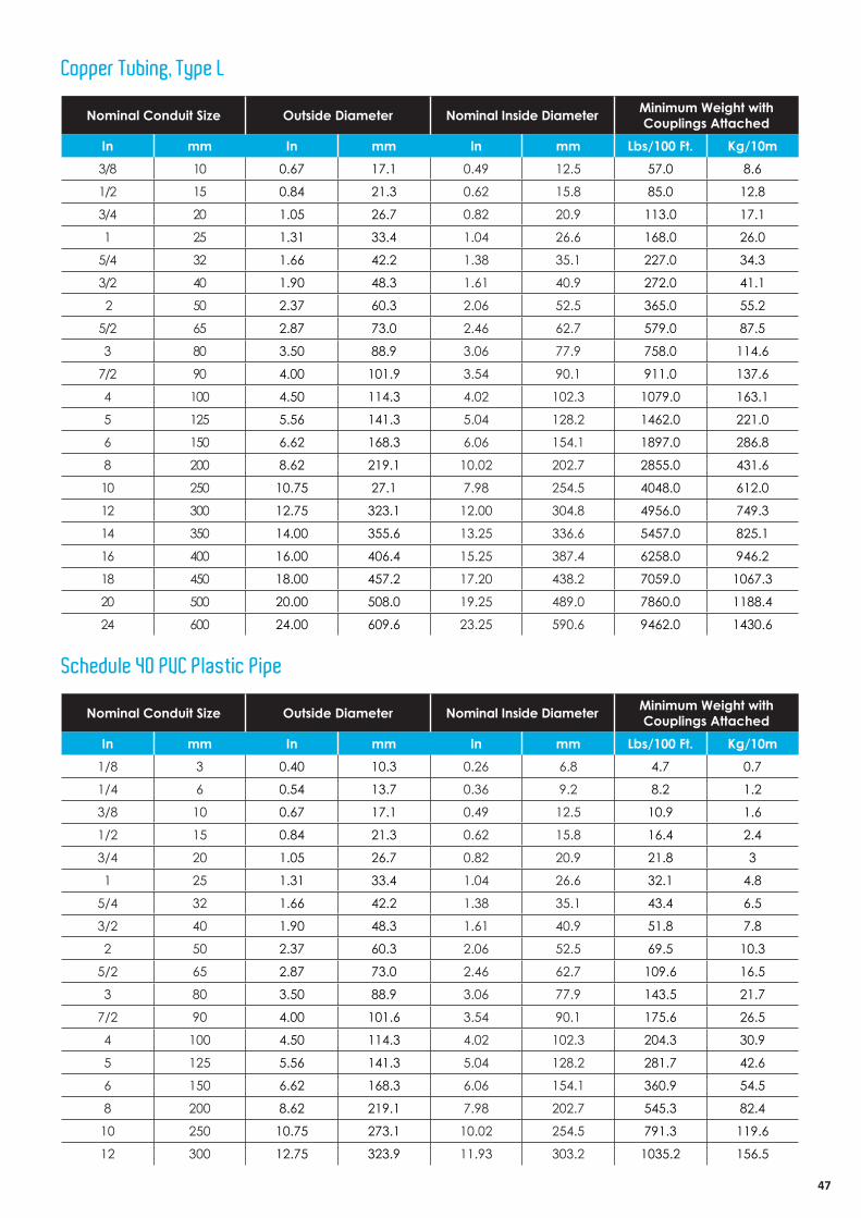
Copper Tubing, Type L
Schedule 40 PVC Plastic Pipe
Nominal Conduit Size Outside Diameter Nominal Inside Diameter Minimum Weight with Couplings Attached
In mm In mm In mm Lbs/100 Ft. Kg/10m3/8 10 0.67 17.1 0.49 12.5 57.0 8.6
1/2 15 0.84 21.3 0.62 15.8 85.0 12.8
3/4 20 1.05 26.7 0.82 20.9 113.0 17.1
1 25 1.31 33.4 1.04 26.6 168.0 26.0
5/4 32 1.66 42.2 1.38 35.1 227.0 34.3
3/2 40 1.90 48.3 1.61 40.9 272.0 41.1
2 50 2.37 60.3 2.06 52.5 365.0 55.2
5/2 65 2.87 73.0 2.46 62.7 579.0 87.5
3 80 3.50 88.9 3.06 77.9 758.0 114.6
7/2 90 4.00 101.9 3.54 90.1 911.0 137.6
4 100 4.50 114.3 4.02 102.3 1079.0 163.1
5 125 5.56 141.3 5.04 128.2 1462.0 221.0
6 150 6.62 168.3 6.06 154.1 1897.0 286.8
8 200 8.62 219.1 10.02 202.7 2855.0 431.6
10 250 10.75 27.1 7.98 254.5 4048.0 612.0
12 300 12.75 323.1 12.00 304.8 4956.0 749.3
14 350 14.00 355.6 13.25 336.6 5457.0 825.1
16 400 16.00 406.4 15.25 387.4 6258.0 946.2
18 450 18.00 457.2 17.20 438.2 7059.0 1067.3
20 500 20.00 508.0 19.25 489.0 7860.0 1188.4
24 600 24.00 609.6 23.25 590.6 9462.0 1430.6
Nominal Conduit Size Outside Diameter Nominal Inside Diameter Minimum Weight with Couplings Attached
In mm In mm In mm Lbs/100 Ft. Kg/10m1/8 3 0.40 10.3 0.26 6.8 4.7 0.7
1/4 6 0.54 13.7 0.36 9.2 8.2 1.2
3/8 10 0.67 17.1 0.49 12.5 10.9 1.6
1/2 15 0.84 21.3 0.62 15.8 16.4 2.4
3/4 20 1.05 26.7 0.82 20.9 21.8 3
1 25 1.31 33.4 1.04 26.6 32.1 4.8
5/4 32 1.66 42.2 1.38 35.1 43.4 6.5
3/2 40 1.90 48.3 1.61 40.9 51.8 7.8
2 50 2.37 60.3 2.06 52.5 69.5 10.3
5/2 65 2.87 73.0 2.46 62.7 109.6 16.5
3 80 3.50 88.9 3.06 77.9 143.5 21.7
7/2 90 4.00 101.6 3.54 90.1 175.6 26.5
4 100 4.50 114.3 4.02 102.3 204.3 30.9
5 125 5.56 141.3 5.04 128.2 281.7 42.6
6 150 6.62 168.3 6.06 154.1 360.9 54.5
8 200 8.62 219.1 7.98 202.7 545.3 82.4
10 250 10.75 273.1 10.02 254.5 791.3 119.6
12 300 12.75 323.9 11.93 303.2 1035.2 156.5
SFSP makes every effort to maintain the accuracy and quality of the information provided in this Catalogue.
However, SFSP cannot guarantee and assumes legal liability or responsibility for the accuracy or completeness of the information provided.
Whilst every care has been exercised in the preparation of this catalogue to ensure that any advice, recommendations or information is accurate, no liability or responsibility of any kind is accepted.
Project working details should be entrusted to appropriately qualified and experienced persons, case by case.
With a policy of continuous product development, SFSP may modify product design and specification without due notice.
In case of any questions or remarks, feel free to contact the R&D Department.