
Catalogue Technique MS02-MSE02 en français. · PDF file20/03/2009 3 CONTENT...
20
T E C H N I C A L C A T A L O G MSE03 HYDRAULIC MOTORS
Transcript of Catalogue Technique MS02-MSE02 en français. · PDF file20/03/2009 3 CONTENT...
T E C H N I C A L C A T A L O G
MSE03HYDRAULIC MOTORS
2 20/03/2009
Modular hydraulic motors MSE03 POCLAIN HYDRAULICS
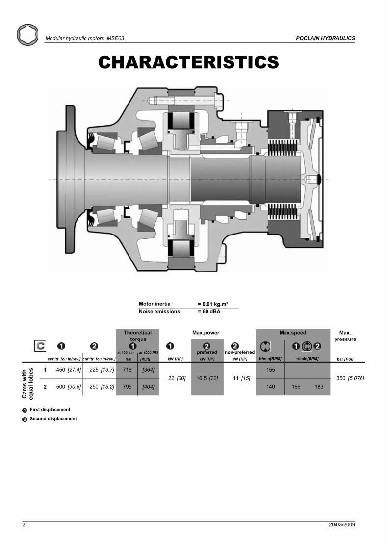
CHARACTERISTICS
1 450 [27.4] 225 [13.7] 716 [364] 155
2 500 [30.5] 250 [15.2] 795 [404] 140 166 18311 [15] 350 [5 076]22 [30] 16.5 [22]
Cam
s w
ith
equa
l lob
es
Theoretical torque
at 100 bar at 1000 PSI
Nm [lb.ft]
Max. pressure
bar [PSI]
Max.power
kW [HP]cm³/tr [cu.in/rev.]cm³/tr [cu.in/rev.]preferred
kW [HP]non-preferred
kW [HP]
Max.speed
tr/min[RPM]tr/min[RPM]
First displacement
Second displacement
Motor inertia = 0.01 kg.m²Noise emissions = 60 dBA

20/03/2009 3
CONTENTPOCLAIN HYDRAULICS Modular hydraulic motors MSE03
Valv
ing
syst
ems
and
hydr
obas
esO
ptio
nsB
rake
Shaf
t mot
orW
heel
mot
or
Mod
ular
ity a
ndM
odel
cod
e
MODULARITY 5MODEL CODE 6
WHEEL MOTOR 8Dimensions for standard (1110) 1-displacement motor 8Dimensions for standard (1110) 2-displacement motor 9Dimensions for standard (1110) Twin-Lock™ motor 9Load curves 10Studs 10
VALVING SYSTEMS AND HYDROBASES 11Dimensions for 1-displacement valving 11Cylinder block splines 11Dimensions for Twin-Lock™ valving 12Chassis mountings 13Hydraulic connections 14Efficiency 14
BRAKES 15Rear brake 15
OPTIONS 17

4 20/03/2009
Modular hydraulic motors MSE03 POCLAIN HYDRAULICS

20/03/2009 5
Valv
ing
syst
ems
and
hydr
obas
esO
ptio
nsB
rake
Shaf
t mot
orW
heel
mot
or
Mod
ular
ity a
ndM
odel
cod
e
POCLAIN HYDRAULICS Modular hydraulic motorsMSE03
MODULARITY
1
C
1 2
D
3 1 2
F
3 1 2
P
3 4 1 2
S
3 4 5 6
S 0 3EM
Hydrobases
Bea
ring
supp
orts
Torq
ue m
odul
e
Valv
ing
syst
ems
Brakes
6 20/03/2009
Modular hydraulic motors MSE03 POCLAIN HYDRAULICS
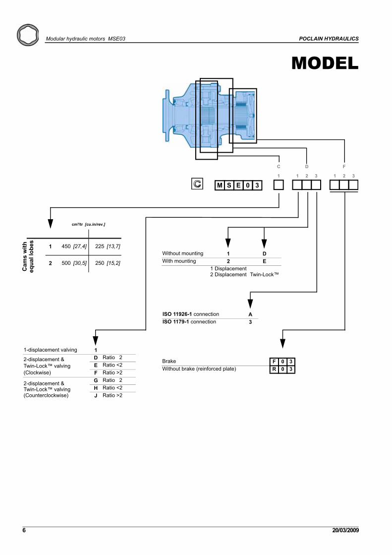
MODEL
S 0 3E1
C
1 2
D
3 1 2
F
3
M
1 450 [27,4] 225 [13,7]
2 500 [30,5] 250 [15,2]
cm³/tr [cu.in/rev.]
Cam
s w
ith
equa
l lob
es
Brake F 0 3Without brake (reinforced plate) R 0 3
1-displacement valving 1
2-displacement &Twin-Lock™ valving(Clockwise)
D Ratio 2E Ratio <2F Ratio >2
2-displacement &Twin-Lock™ valving(Counterclockwise)
G Ratio 2H Ratio <2J Ratio >2
Without mounting 1 DWith mounting 2 E
1 Displacement2 Displacement Twin-Lock™
ISO 11926-1 connection AISO 1179-1 connection 3
MODEL CODE

20/03/2009 7
Valv
ing
syst
ems
and
hydr
obas
esO
ptio
nsB
rake
Shaf
t mot
orW
heel
mot
or
Mod
ular
ity a
ndM
odel
cod
e
POCLAIN HYDRAULICS Modular hydraulic motorsMSE03
CODE
01 2
P
3 4 1 2
S
3 4 5 6
0 Without bearing support1 Without mounting
Without shaft 05 x Ø18 on Ø140 1
Without Options or Adaptations 0T4 Speed sensor installed 2Brake environmental cover without plug 3Diamond™ 7Predisposition for speed sensor 8Special paint or no paint DReinforced sealing ESpecial wheel rim mounting GHigh efficiency HSurface heat treatment of the shaft JTR Speed sensor installed S
Without studs 1With studs + nuts 2With studs 3

8 20/03/2009
Modular hydraulic motors MSE03 POCLAIN HYDRAULICS
Methodology :This document is intended for manufacturers of machines that incorporate Poclain Hydraulics products. It describes the technical characteristics of Poclain Hydraulics products and specifies installation conditions that will ensure optimum operation. This document includes important comments concerning safety. They are indicated in the following way:
This document also includes essential operating instructions for the product and general information. These are indicated in the following way:
The views in this document are created using metric standards. The dimensional data is given in mm and in inches (inches are between brackets and italic)
Safety comment.
Essential instructions.
General information .
Information on the model code.
Weight of component without oil.
Volume of oil.
Units.
Tightening torque.
Screws.
Information intended for Poclain-Hydraulics personnel.
26 kg [57 lb] 32 kg [70 lb]
0,70 L [42 cu.in] 0,60 L [36 cu.in]
Dimensions for standard (1110) 1-displacement motor
WHEEL MOTOR

20/03/2009 9
Valv
ing
syst
ems
and
hydr
obas
esO
ptio
nsB
rake
Shaf
t mot
orW
heel
mot
or
Mod
ular
ity a
ndM
odel
cod
e
POCLAIN HYDRAULICS Modular hydraulic motorsMSE03
WHEEL MOTOR
Also see 'Valving systems and hydrobases' section (thumbnail opposite).
26 kg [57 lb] 32 kg [70 lb]
0,70 L [42 cu.in] 0,60 L [36 cu.in]
Dimensions for standard (1110) 2-displacement motor
26 kg [57 lb] 32 kg [70 lb]
0,70 L [42 cu.in] 0,60 L [36 cu.in]
Dimensions for standard (1110) Twin-Lock™ motor
10 20/03/2009
Modular hydraulic motors MSE03 POCLAIN HYDRAULICS
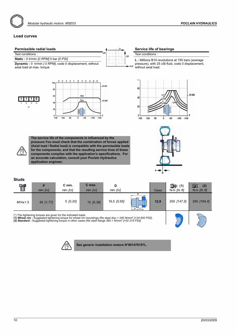
Load curves
Studs
Permissible radial loads Service life of bearingsTest conditions : Test conditions : Static : 0 tr/min [0 RPM] 0 bar [0 PSI] L : Millions B10 revolutions at 150 bars (average
pressure), with 25 cSt fluid, code 0 displacement, without axial load.
Dynamic : 0 tr/min [ 0 RPM], code 0 displacement, without axial load at max. torque
1 1 1 01 2 3 4
P
See generic installation motors N°801478197L.
The service life of the components is influenced by the pressure.You must check that the combination of forces applied (Axial load / Radial load) is compatible with the permissible loads for the components, and that the resulting service lives of these components complies with the application's specifications. For an accurate calculation, consult your Poclain Hydraulics application engineer.
mm [in] mm [in] mm [in] mm [in] N.m [lb.ft] N.m [lb.ft]
M14x1.5 45 [1,77] 5 [0,20] 10 [0,39] 16,5 [0,65] 12,9 200 [147,5] 250 [184,4]
(1) (2)P D
(*) The tightening torques are given for the indicated loads.(1) Wheel rim : Suggested tightening torque for wheel rim mountings (Re steel disc > 240 N/mm² [>34 800 PSI]).(2) Standard : Suggested tightening torque in other cases (Re steel flange 360 > N/mm² [>52 215 PSI])
ClassC min. C max.
20/03/2009 11
Valv
ing
syst
ems
and
hydr
obas
esO
ptio
nsB
rake
Shaf
t mot
orW
heel
mot
or
Mod
ular
ity a
ndM
odel
cod
e
POCLAIN HYDRAULICS Modular hydraulic motorsMSE03
VALVING SYSTEMS AND HYDROBASES
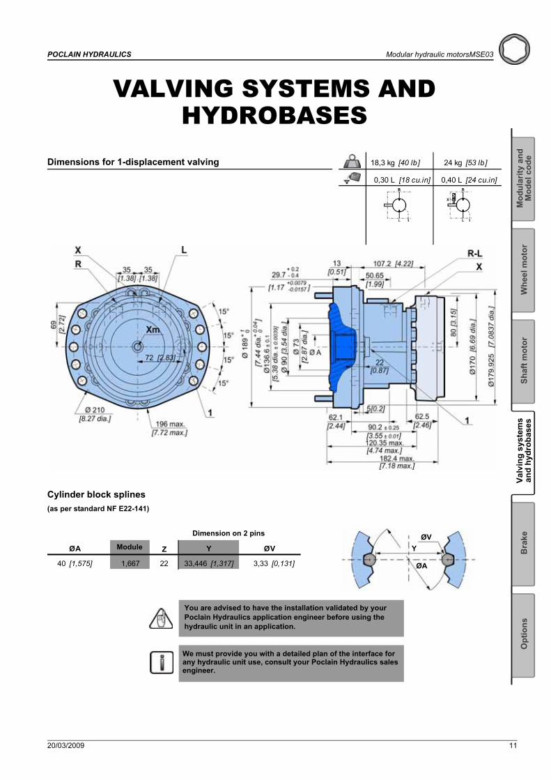
Cylinder block splines(as per standard NF E22-141)
You are advised to have the installation validated by your Poclain Hydraulics application engineer before using the hydraulic unit in an application.
We must provide you with a detailed plan of the interface for any hydraulic unit use, consult your Poclain Hydraulics sales engineer.
18,3 kg [40 lb] 24 kg [53 lb]
0,30 L [18 cu.in] 0,40 L [24 cu.in]
Dimensions for 1-displacement valving
1,667 2240
Y ØVØA
33,446 [1,317]
Z
3,33 [0,131][1,575]
Dimension on 2 pins
Module
ØA
YØV

12 20/03/2009
Modular hydraulic motors MSE03 POCLAIN HYDRAULICS
17,3 kg [38 lb] 23,0 kg [51 lb]
0,30 L [18 cu.in] 0,40 L [24 cu.in]
Dimensions for 2-displacement valving
17,3 kg [38 lb] 23,0 kg [51 lb]
0,30 L [18 cu.in] 0,40 L [24 cu.in]
Dimensions for Twin-Lock™ valving
20/03/2009 13
Valv
ing
syst
ems
and
hydr
obas
esO
ptio
nsB
rake
Shaf
t mot
orW
heel
mot
or
Mod
ular
ity a
ndM
odel
cod
e
POCLAIN HYDRAULICS Modular hydraulic motorsMSE03
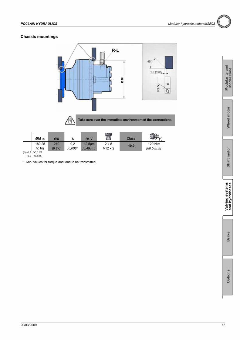
Chassis mountings
Take care over the immediate environment of the connections.
ØM (1) ØU S Ra V (*) 180,25 210 0,2 12,5μm 120 N.m[7,10] [8,27] [0,008] [0,49μin] [88,5 lb.ft]
(1) +0,3 [+0,012]+0,2 [+0,008]
2 x 5 M12 x 2
10,9
Class
* : Min. values for torque and load to be transmitted.
14 20/03/2009
Modular hydraulic motors MSE03 POCLAIN HYDRAULICS
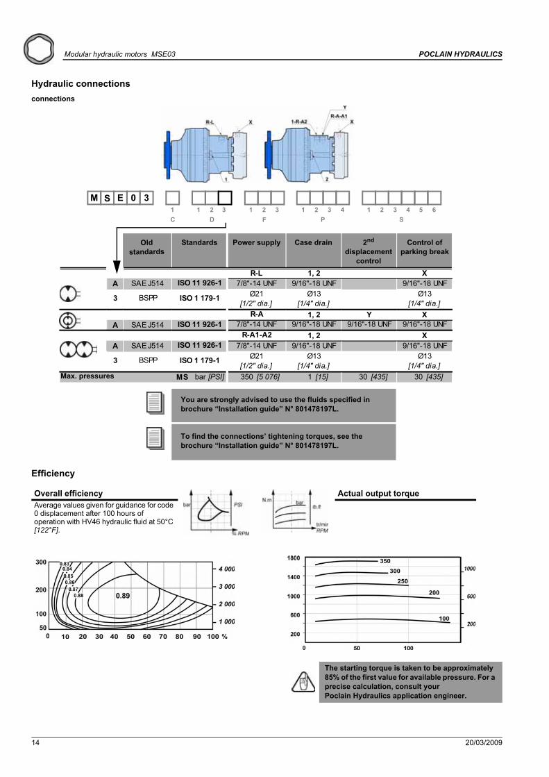
Hydraulic connectionsconnections
Efficiency
You are strongly advised to use the fluids specified in brochure “Installation guide” N° 801478197L.
To find the connections’ tightening torques, see the brochure “Installation guide” N° 801478197L.
Overall efficiency Actual output torqueAverage values given for guidance for code 0 displacement after 100 hours of operation with HV46 hydraulic fluid at 50°C [122°F].
The starting torque is taken to be approximately 85% of the first value for available pressure. For a precise calculation, consult your Poclain Hydraulics application engineer.
A SAE J514
A SAE J514
A SAE J514
MS bar [PSI] 350 [5 076] 1 [15] 30 [435] 30 [435]
[1/2" dia.]
1, 29/16"-18 UNF9/16"-18 UNF
Ø21ISO 11 926-1 7/8"-14 UNF
R-L
3 BSPP
X
ISO 1 179-1 Ø13
X[1/4" dia.]
Ø13[1/4" dia.]
9/16"-18 UNFY
ISO 11 926-1 7/8"-14 UNF 9/16"-18 UNF 9/16"-18 UNF
3 BSPP ISO 1 179-1 Ø21[1/2" dia.]
R-A1-A2 1, 2
R-A 1, 2
XISO 11 926-1 7/8"-14 UNF 9/16"-18 UNF 9/16"-18 UNF
[1/4" dia.] [1/4" dia.]Ø13Ø13
1 1 2M 0 3S E
1 2 3 4 5 6S
1 2 3 4PDC F
1 2 33
Standards Power supply Case drain Control of parking break
2nd displacement
control
Old standards
Max. pressures
20/03/2009 15
Valv
ing
syst
ems
and
hydr
obas
esO
ptio
nsB
rake
Shaf
t mot
orW
heel
mot
or
Mod
ular
ity a
ndM
odel
cod
e
POCLAIN HYDRAULICS Modular hydraulic motorsMSE03
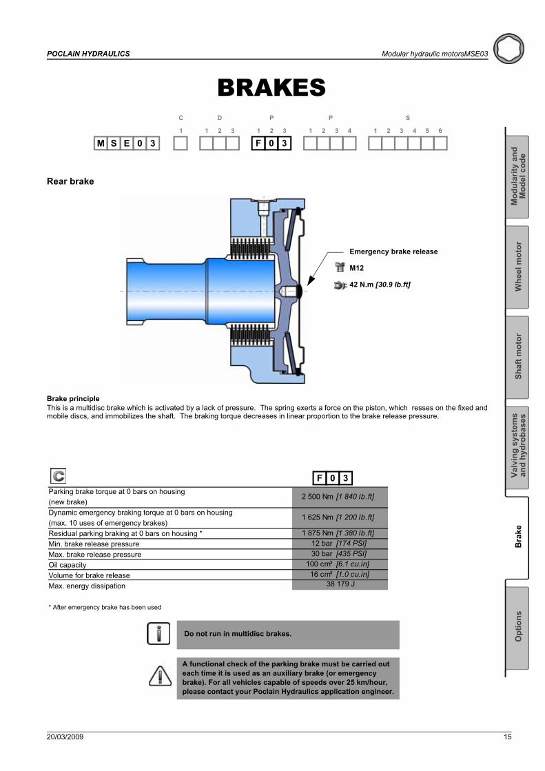
BRAKES
Rear brake
Do not run in multidisc brakes.
A functional check of the parking brake must be carried out each time it is used as an auxiliary brake (or emergency brake). For all vehicles capable of speeds over 25 km/hour, please contact your Poclain Hydraulics application engineer.
F 0 31
C
1 2
D
3 1 2
P
3 1 2
P
3 4 1 2
S
3 4 5 6
S 0 3EM
Brake principleThis is a multidisc brake which is activated by a lack of pressure. The spring exerts a force on the piston, which resses on the fixed and mobile discs, and immobilizes the shaft. The braking torque decreases in linear proportion to the brake release pressure.
Emergency brake release
M12
42 N.m [30.9 lb.ft]
2 500 Nm [1 840 lb.ft] 3 000 Nm [2 210 lb.ft]
1 625 Nm [1 200 lb.ft] 1 950 Nm [1 440 lb.ft]
1 875 Nm [1 380 lb.ft] 2 250 Nm [1 660 lb.ft]12 bar [174 PSI] 20 bar [290 PSI]30 bar [435 PSI] 30 bar [435 PSI]
100 cm³ [6.1 cu.in] 100 cm³ [6.1 cu.in]16 cm³ [1.0 cu.in] 16 cm³ [1.0 cu.in]
38 179 J 6 109 J
F 0 3Parking brake torque at 0 bars on housing (new brake)Dynamic emergency braking torque at 0 bars on housing (max. 10 uses of emergency brakes)Residual parking braking at 0 bars on housing *Min. brake release pressureMax. brake release pressureOil capacityVolume for brake releaseMax. energy dissipation
* After emergency brake has been used

16 20/03/2009
Modular hydraulic motors MSE03 POCLAIN HYDRAULICS

20/03/2009 17
Valv
ing
syst
ems
and
hydr
obas
esO
ptio
nsB
rake
Shaf
t mot
orW
heel
mot
or
Mod
ular
ity a
ndM
odel
cod
e
POCLAIN HYDRAULICS Modular hydraulic motorsMSE03
OPTIONS
You can accumulate more than one optional part. Consult your Poclain Hydraulics sales engineer.
1
C
1 2
D
3 1 2
F
3 1 2
P
3 4 1 2
S
3 4 5 6
S 0 3EM
2 - S - 8 - Installed speed sensor or predisposition
3 - Brake environmental cover without plugNo plug or hole in the cover.(see figure opposite)
Look at the "Mobile Electronic" N° A01889D technical catalogue for the sensor specifications and its connection.
To install the sensor, see the ''Installation guide'' brochure No. 801478197L.
DesignationT4 Speed sensor installed 2TR Speed sensor installed SPredisposition for speed sensor 8
A-A
Max. length Y=Standard number of pulses per revolution=
1940
18 20/03/2009
Modular hydraulic motors MSE03 POCLAIN HYDRAULICS
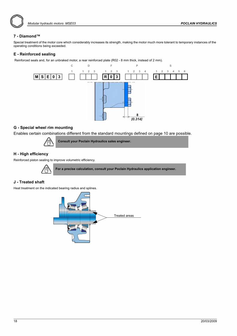
7 - Diamond™Special treatment of the motor core which considerably increases its strength, making the motor much more tolerant to temporary instances of the operating conditions being exceeded.
E - Reinforced sealing Reinforced seals and, for an unbraked motor, a rear reinforced plate (R02 - 8 mm thick, instead of 2 mm).
G - Special wheel rim mountingEnables certain combinations different from the standard mountings defined on page 10 are possible.
H - High efficiencyReinforced piston sealing to improve volumetric efficiency.
J - Treated shaftHeat treatment on the indicated bearing radius and splines.
Consult your Poclain Hydraulics sales engineer.
R 0 3 E1
C
1 2
D
3 1 2
F
3 1 2
P
3 4 1 2
S
3 4 5 6
S 0 3EM
For a precise calculation, consult your Poclain Hydraulics application engineer.
Treated areas

20/03/2009 19
POCLAIN HYDRAULICS Modular hydraulic motorsMSE03

20/03/2009
Poclain Hydraulics reserves the right to make any modifications it deems necessary to the products described in this document without prior notification.The information contained in this document must be confirmed by Poclain Hydraulics before any order is submitted.Illustrations are not binding.The Poclain Hydraulics brand is the property of Poclain Hydraulics S.A.
Thirteen subsidiaries and a worldwide network of more than 150 distributors and partners …
801 478 117Z
801 478 187A
801 478 199N
801 578 112P
801 578 124C


![Catalogue Technique MS02-MSE02 en français. · 6 01/09/2009 Modular hydraulic motors MSE03 POCLAIN HYDRAULICS LM s u V i R o R e p i R e q i v 1 450 [27,4] 225 [13,7] 2 500 [30,5]](https://static.fdocuments.in/doc/165x107/5ea5d17c6651da1015339423/catalogue-technique-ms02-mse02-en-franfais-6-01092009-modular-hydraulic-motors.jpg)


![Catalogue Technique MS02-MSE02 en français. · 4 18/02/2016 High performance motor MHP20/MHP27 POCLAIN HYDRAULICS MHP27 CHARACTERISTICS Max. Pressure bar [PSI] 500 [7252] 1C Distribution](https://static.fdocuments.in/doc/165x107/604122bbf7e43d65ce4d1fb9/catalogue-technique-ms02-mse02-en-franais-4-18022016-high-performance-motor.jpg)


![Catalogue Technique MS02-MSE02 en français. · Modular hydraulic motors MS83 POCLAIN HYDRAULICS 15/11/2016 2 CHARACTERISTICS Motor inertia 2 kg.m² 8 6 679 [407,4] 3 340 [203,7]](https://static.fdocuments.in/doc/165x107/604122bbf7e43d65ce4d1fb8/catalogue-technique-ms02-mse02-en-franais-modular-hydraulic-motors-ms83-poclain.jpg)