Catalogue EN 2020 - Centrowent
36
2 0 2 0 C A T A LOGUE CONTROL SYSTEMS TECHNOLOGIES
Transcript of Catalogue EN 2020 - Centrowent

2 0
2 0
C A
T A
L
OG
UE
CONTROL SYSTEMS TECHNOLOGIES
CONTROL SYSTEMS TECHNOLOGIES
www.vtsistema.com
CONTROL SYSTEMS TECHNOLOGIES
CONTROL SYSTEMS TECHNOLOGIES
Control system for AHU...............................................................................................................Electronic speed controllers ERV ..B, ERV ..T.................................................................................Electronic speed controllers ERV ..TMB; poten�ometer EC 10....................................................Setpoint poten�ometer with relay output ECS10; controller ECS10-PWM.................................Transformer fan speed controllers RV..B, RV ..............................................................................Transformer fan speed controllers RT.., RT ..EX..........................................................................Transformer fan speed controllers RV..B-2, RV ..-2.....................................................................Transformer fan speed controllers RT ..-2, RV ..YS.......................................................................Transformer fan speed controllers RT ..YS; controllers for two speeds fan motor RD .., RD ..EX..Controllers with TMM6-3V thermostat for fan heater.................................................................Controllers with TEM 3TD thermostat for fan heater...................................................................2 and 3 steps switches SW3, SW4; pressure switches SR ............................................................ Frequency inverters, external speed setpoint RES 001/10kom/ON/OFF.....................................Frequency inverters, external speed setpoint RES 001/10kom/ON/OFF.....................................Electronic controllers for electrical hea�ng REC16, REC16MB, REC25, REC25B, REC50, REC50B Electric circular duct heaters/preheaters for ven�la�on systems EHC ......................................Electric rectangular duct heaters/preheaters for ven�la�on systemsEHR ................................Hea�ng elements........................................................................................................................Air damper actuators without spring return and with spring return...........................................Room thermostats TEM16, TMM6, TMM6-3V............................................................................TEM 16TD and TEM 3TD series touch screen thermostats..........................................................
4
5678
91011121314
18
19
222829
30313233
1716
Contents
15
Frost protec�on thermostat FT 6.0............................................................................................Capillary and surface thermostats..............................................................................................Autotransformers, transformers, safety transformers............................................................... 34Note............................................................................................................................................. 35
www.vtsistema.com
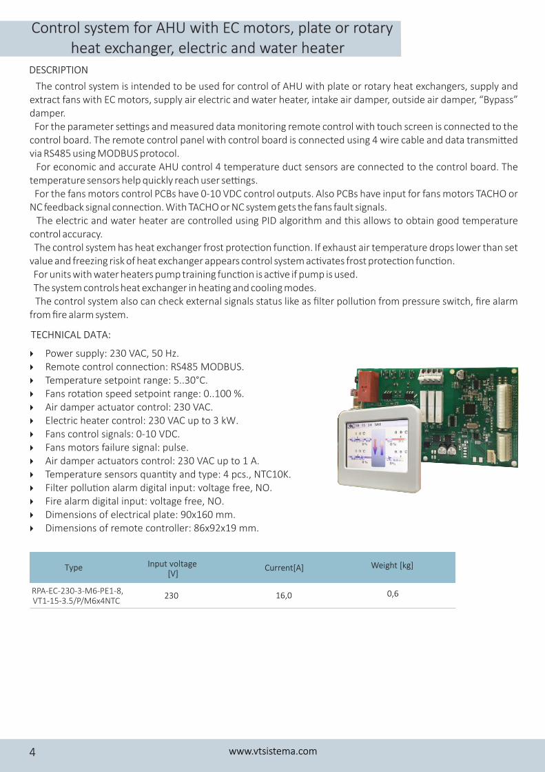
4 Power supply: 230 VAC, 50 Hz.4 Remote control connec�on: RS485 MODBUS.4 Temperature setpoint range: 5..30°C. 4 Fans rota�on speed setpoint range: 0..100 %. 4 Air damper actuator control: 230 VAC.4 Electric heater control: 230 VAC up to 3 kW.4 Fans control signals: 0-10 VDC.4 Fans motors failure signal: pulse.4 Air damper actuators control: 230 VAC up to 1 A.4 Temperature sensors quan�ty and type: 4 pcs., NTC10K.4 Filter pollu�on alarm digital input: voltage free, NO.4 Fire alarm digital input: voltage free, NO.4 Dimensions of electrical plate: 90x160 mm.4 Dimensions of remote controller: 86x92x19 mm.
Control system for AHU with EC motors, plate or rotaryheat exchanger, electric and water heater
The control system is intended to be used for control of AHU with plate or rotary heat exchangers, supply and extract fans with EC motors, supply air electric and water heater, intake air damper, outside air damper, “Bypass” damper. For the parameter se�ngs and measured data monitoring remote control with touch screen is connected to the control board. The remote control panel with control board is connected using 4 wire cable and data transmi�ed via RS485 using MODBUS protocol. For economic and accurate AHU control 4 temperature duct sensors are connected to the control board. The temperature sensors help quickly reach user se�ngs. For the fans motors control PCBs have 0-10 VDC control outputs. Also PCBs have input for fans motors TACHO or NC feedback signal connec�on. With TACHO or NC system gets the fans fault signals. The electric and water heater are controlled using PID algorithm and this allows to obtain good temperature control accuracy. The control system has heat exchanger frost protec�on func�on. If exhaust air temperature drops lower than set value and freezing risk of heat exchanger appears control system ac�vates frost protec�on func�on. For units with water heaters pump training func�on is ac�ve if pump is used. The system controls heat exchanger in hea�ng and cooling modes. The control system also can check external signals status like as filter pollu�on from pressure switch, fire alarm from fire alarm system.
TECHNICAL DATA:
Type Input voltage [V]
230RPA-EC-230-3-M6-PE1-8,VT1-15-3.5/P/M6x4NTC
Weight [kg]
0,6
Current[A]
16,0
DESCRIPTION
www.vtsistema.com4
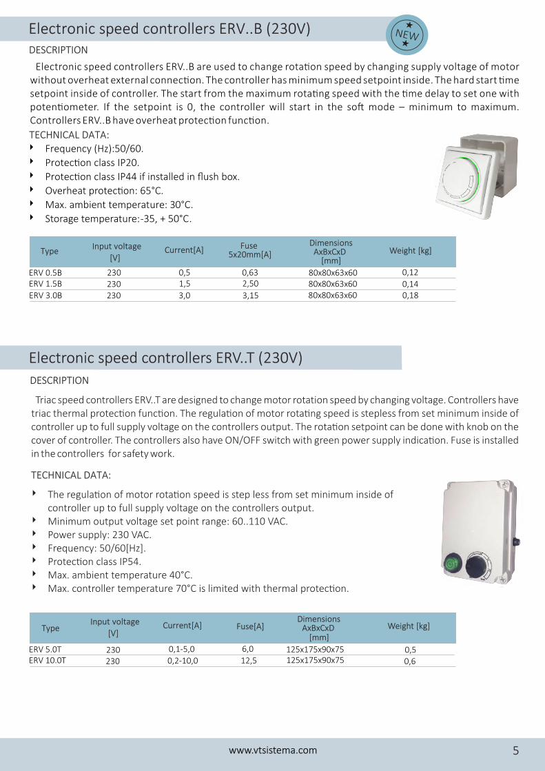
Electronic speed controllers ERV..B (230V)
Electronic speed controllers ERV..B are used to change rota�on speed by changing supply voltage of motor without overheat external connec�on. The controller has minimum speed setpoint inside. The hard start �me setpoint inside of controller. The start from the maximum rota�ng speed with the �me delay to set one with poten�ometer. If the setpoint is 0, the controller will start in the so� mode – minimum to maximum. Controllers ERV..B have overheat protec�on func�on.
4 Frequency (Hz):50/60.
4 Protec�on class IP20.
4 Protec�on class IP44 if installed in flush box.
4 Overheat protec�on: 65°C.
4 Max. ambient temperature: 3 °C.0
4 Storage temperature: -35, + 50°C.
Type Current[A] Weight [kg]Input voltage
[V]
Fuse 5x20mm[A]
TECHNICAL DATA:
NEW
DESCRIPTION
ERV 1.5B
ERV 3.0B
1,5
3,0 0,14 0,18
230230
2,50
3,15
ERV 0.5B
Dimensions AxBxCxD
[mm]
80x80x63x6080x80x63x60
80x80x63x600,63230 0,5 0,12
Triac speed controllers ERV..T are designed to change motor rotation speed by changing voltage. Controllers have triac thermal protec�on func�on. The regula�on of motor rota�ng speed is stepless from set minimum inside of controller up to full supply voltage on the controllers output. The rota�on setpoint can be done with knob on the cover of controller. The controllers also have ON/OFF switch with green power supply indica�on. Fuse is installed in the controllers for safety work.
4 The regula�on of motor rota�on speed is step less from set minimum inside of controller up to full supply voltage on the controllers output.
4 Minimum output voltage set point range: 60..110 VAC.4 Power supply: 230 VAC.4 Frequency: 50/60[Hz].4 Protec�on class IP54.4 Max. ambient temperature 40°C.4 Max. controller temperature 70°C is limited with thermal protec�on.
Electronic speed controllers ERV..T (230V)
Dimensions AxBxCxD
[mm]Fuse[A]
ERV 5.0TERV 10.0T
230230
0,1-5,0
0,2-10,0 125x175x90x75125x175x90x75
0,6
0,56,0
12,5
TECHNICAL DATA:
DESCRIPTION
www.vtsistema.com 5
Type Current[A] Weight [kg]Input voltage
[V]
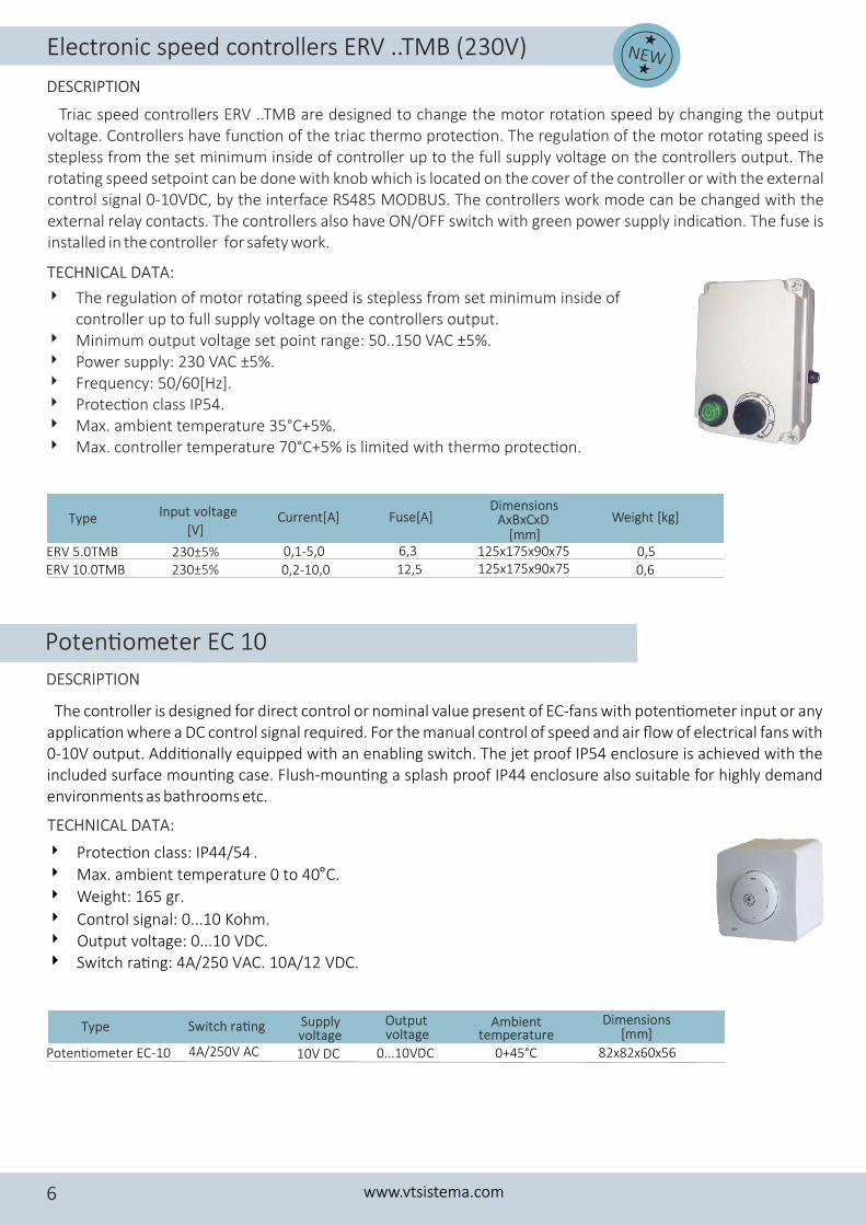
Triac speed controllers ERV ..TMB are designed to change the motor rotation speed by changing the output voltage. Controllers have func�on of the triac thermo protec�on. The regula�on of the motor rota�ng speed is stepless from the set minimum inside of controller up to the full supply voltage on the controllers output. The rota�ng speed setpoint can be done with knob which is located on the cover of the controller or with the external control signal 0-10VDC, by the interface RS485 MODBUS. The controllers work mode can be changed with the external relay contacts. The controllers also have ON/OFF switch with green power supply indica�on. The fuse is installed in the controller for safety work.
4 The regula�on of motor rota�ng speed is stepless from set minimum inside of controller up to full supply voltage on the controllers output.
4 Minimum output voltage set point range: 50..150 VAC 5± %.4 Power supply: 230 VAC 5± %.4 Frequency: 50/60[Hz].4 Protec�on class IP54.4 Max. ambient temperature 35°C+5%.4 Max. controller temperature 70°C+5% is limited with thermo protec�on.
TECHNICAL DATA:
Type Current[A] Weight [kg]Input voltage
[V]
Dimensions AxBxCxD
[mm]Fuse[A]
ERV 5.0TMBERV 10.0TMB
230± %5230± %5
0,1-5,0
0,2-10,0 125x175x90x75125x175x90x75
0,6
0,56,3
12,5
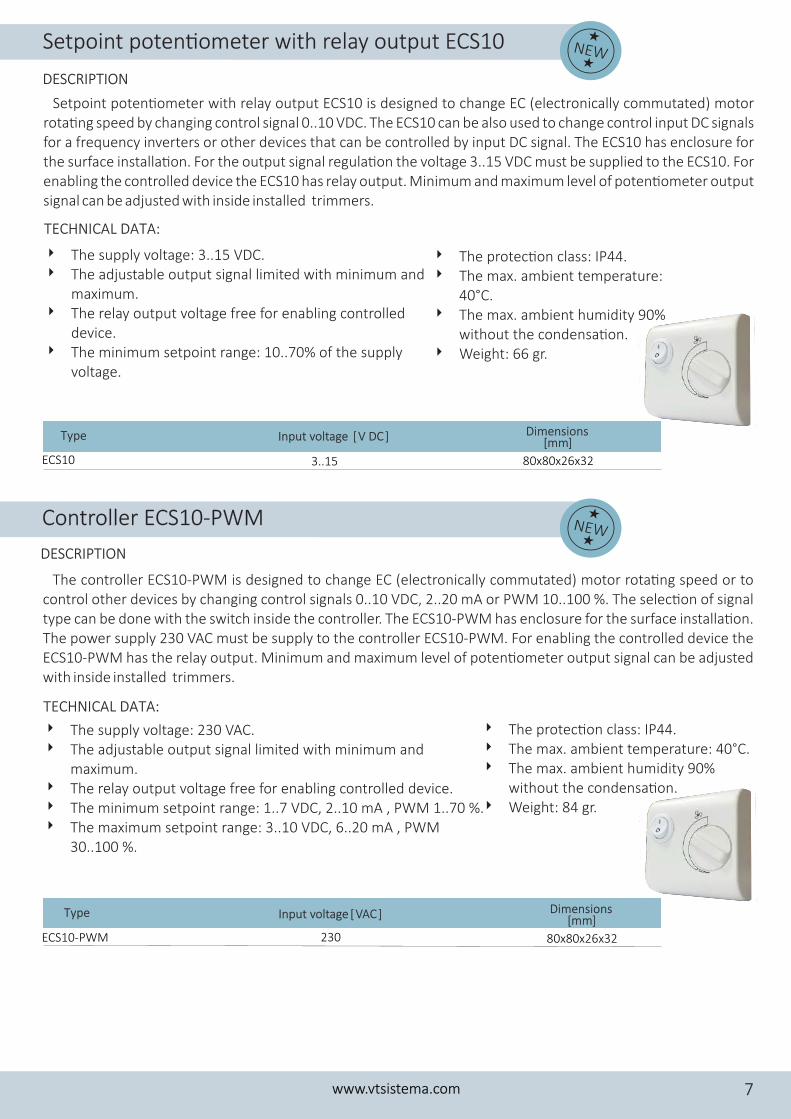
Poten�ometer EC 10
The controller is designed for direct control or nominal value present of EC-fans with poten�ometer input or any applica�on where a DC control signal required. For the manual control of speed and air flow of electrical fans with 0-10V output. Addi�onally equipped with an enabling switch. The jet proof IP54 enclosure is achieved with the included surface moun�ng case. Flush-moun�ng a splash proof IP44 enclosure also suitable for highly demand environments as bathrooms etc.
Type Switch ra�ng Supply
Poten�ometer EC-10 4A/250V AC 10V DC
Dimensions
82x82x60x56
[mm]
4 Control signal: 0...10 Kohm.4 Output voltage: 0...10 VDC.44 Switch ra�ng: 4A/250 VAC. 10A/12 VDC.
4 Protec�on class: IP44/54 .
4 Max. ambient temperature 0 to 40°C.
4 Weight: 165 gr.
TECHNICAL DATA:
DESCRIPTION
NEW
DESCRIPTION
Electronic speed controllers ERV ..TMB (230V)
www.vtsistema.com6
voltageOutput
0...10VDC 0+45°C
Ambient temperaturevoltage
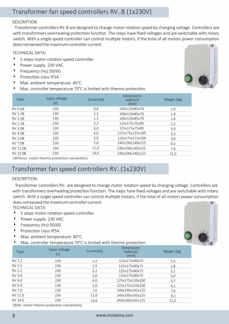
The controller ECS10-PWM is designed to change EC (electronically commutated) motor rota�ng speed or to control other devices by changing control signals 0..10 VDC, 2..20 mA or PWM 10..100 %. The selec�on of signal type can be done with the switch inside the controller. The ECS10-PWM has enclosure for the surface installa�on. The power supply 230 VAC must be supply to the controller ECS10-PWM. For enabling the controlled device the ECS10-PWM has the relay output. Minimum and maximum level of poten�ometer output signal can be adjusted with inside installed trimmers.
4 The supply voltage: 230 VAC.4 The adjustable output signal limited with minimum and
maximum.4 The relay output voltage free for enabling controlled device.4 The minimum setpoint range: 1..7 VDC, 2..10 mA , PWM 1..70 %.4 The maximum setpoint range: 3..10 VDC, 6..20 mA , PWM
30..100 %.
4 The protec�on class: IP44.4 The max. ambient temperature: 40°C.4 The max. ambient humidity 90%
without the condensa�on.4 Weight: 84 gr.
Type
ECS10-PWM
Input voltage [VAC ]
230 80x80x26x32
Dimensions [mm]
TECHNICAL DATA:
DESCRIPTION
Setpoint poten�ometer with relay output ECS10 is designed to change EC (electronically commutated) motor rota�ng speed by changing control signal 0..10 VDC. The ECS10 can be also used to change control input DC signals for a frequency inverters or other devices that can be controlled by input DC signal. The ECS10 has enclosure for the surface installa�on. For the output signal regula�on the voltage 3..15 VDC must be supplied to the ECS10. For enabling the controlled device the ECS10 has relay output. Minimum and maximum level of poten�ometer output signal can be adjusted with inside installed trimmers.
4 The supply voltage: 3..15 VDC.4 The adjustable output signal limited with minimum and
maximum.4 The relay output voltage free for enabling controlled
device.4 The minimum setpoint range: 10..70% of the supply
voltage.
4 The protec�on class: IP44.4 The max. ambient temperature:
40°C.4 The max. ambient humidity 90%
without the condensa�on. 4 Weight: 66 gr.
TECHNICAL DATA:
ECS10 3..15
Type Input voltage [V DC ]
80x80x26x32
Dimensions [mm]
NEW
DESCRIPTION
Setpoint poten�ometer with relay output ECS10
NEWController ECS10-PWM
www.vtsistema.com 7
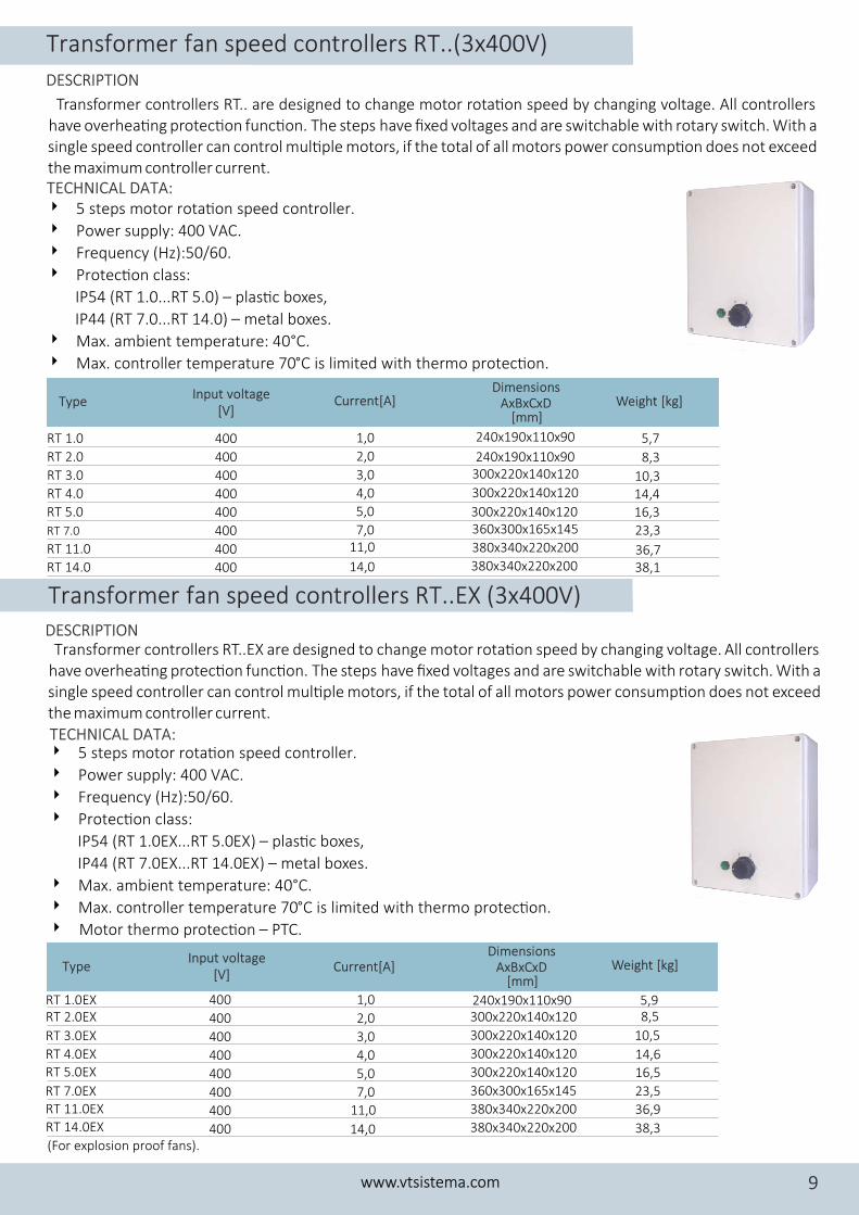
Transformer fan speed controllers RV..(1x230V)
Transformer fan speed controllers RV..B (1x230V)
Transformer controllers RV..B are designed to chan or rota�on speed by changing voltage. C ontrollers are ge motwith transformers overhea�ng protec�on func�on. The steps have fixed voltages and are switchable with rotary switch. With a single speed controller can control mul�ple motors, if the total of all motors power consump�on does not exceed the maximum controller current.
4 5 steps motor rota�on speed controller.
4 Power supply: 230 VAC.
4 Frequency (Hz):50/60.
4 Protec�on class IP54.
4 Max. ambient temperature: 40°C.
4 Max. controller temperature 70°C is limited with thermo protec�on.
(Without motor thermo protec�on connec�on).
Type Current[A] Weight [kg]Input voltage [V]
Dimensions AxBxCxD
[mm]
RV 1.2B 1,2
RV 1.5B 1,5
RV 2.2B 2,2
RV 3.0B 3,0
RV 4.0B 4,0
RV 5.0B 5,0
RV 7.0B 7,0
RV 11.0B 11,0
RV 14.0B 14,0
RV 0.6B 230
230
230
230
230
230
230
230
230
230 0,6
1,4 1,6
2,2
3,0
3,2
3,6
6,5
7,6 11,2
1,0
125x175x115x100
240x190x140x125
100x120x85x70
125x175x75x90
100x120x85x70100x120x85x70
125x175x75x90
125x175x115x100
240x190x140x125
240x190x140x125
TECHNICAL DATA:
DESCRIPTION
(With motor thermo protec�on connec�on).
Type Current[A] Weight [kg]Input voltage
[V]
Dimensions
RV 3.0 230
RV 4.0 230
RV 5.0 230
RV 7.0 230
RV 11.0 230
RV 14.0 230
RV 1.2 230
RV 1.5 230
RV 2.2 230
3,04,0
5,07,0
11,0
14,0
1,2
1,5
2,2
3,0
3,7
4,1
7,0
8,111,2
1,6
1,82,2
125x175x120x100
240x190x145x125
125x175x90x75
125x175x90x75
125x175x90x75125x175x90x75
125x175x120x100
240x190x145x125
240x190x145x125
Transformer controllers RV.. are designed to change motor rota�on speed by changing voltage. Controllers are with transformers overhea�ng protec�on func�on. The steps have fixed voltages and are switchable with rotary switch. With a single speed controller can control mul�ple motors, if the total of all motors power consump�on does not exceed the maximum controller current.
4 5 steps motor rota�on speed controller.
4 Power supply: 230 VAC.
4 Frequency (Hz):50/60.
4 Protec�on class IP54.
4 Max. ambient temperature: 40°C.
4 Max. controller temperature 70°C is limited with thermo protec�on.
Type Current[A] Weight [kg]Input voltage [V]
Dimensions AxBxCxD
[mm]
TECHNICAL DATA:
DESCRIPTION
www.vtsistema.com8
Transformer fan speed controllers RT..EX (3x400V)
Transformer controllers RT.. are designed to change motor rota�on speed by changing voltage. All controllers have overhea�ng protec�on func�on. The steps have fixed voltages and are switchable with rotary switch. With a single speed controller can control mul�ple motors, if the total of all motors power consump�on does not exceed the maximum controller current.
4 5 steps motor rota�on speed controller.
4 Power supply: 400 VAC.
4 Frequency (Hz):50/60.
4 Protec�on class:
IP54 (RT 1.0...RT 5.0) – plas�c boxes,
IP44 (RT 7.0...RT 14.0) – metal boxes.
4 Max. ambient temperature: 40°C.
4 Max. controller temperature 70°C is limited with thermo protec�on.
Type Current[A] Weight [kg]Input voltage [V]
Dimensions AxBxCxD
[mm]
RT 1.0
RT 2.0
RT 3.0
RT 4.0
RT 5.0
RT 7.0
RT 11.0
RT 14.0
400
400
400
400
400
400
400
400
1,0
2,0
3,0
4,0
5,0
7,011,0
14,0
5,7
8,3
10,314,416,3
23,3
36,738,1
240x190x110x90
300x220x140x120
360x300x165x145
380x340x220x200
240x190x110x90
300x220x140x120
300x220x140x120
380x340x220x200
TECHNICAL DATA:
DESCRIPTION
Transformer controllers RT..EX are designed to change motor rota�on speed by changing voltage . All controllers have overhea�ng protec�on func�on. ch. With a The steps h ave fixed voltages and are switchable with rotary switsingle speed controller can control mul�ple motors, if the total of all motors power consump�on does not exceed the maximum controller current.
4 5 steps motor rota�on speed controller.
4 Power supply: 400 VAC.
4 Frequency (Hz):50/60.
4 Protec�on class:
IP54 (RT 1.0EX...RT 5.0EX) – plas�c boxes,
IP44 (RT 7.0EX...RT 14.0EX) – metal boxes.
4 Max. ambient temperature: 40°C.
4 Max. controller temperature 70°C is limited with thermo protec�on.
4 Motor thermo protec�on – PTC.
TECHNICAL DATA:
(For explosion proof fans).
RT 1.0EXRT 2.0EX
RT 3.0EX
RT 4.0EXRT 5.0EX
RT 7.0EXRT 11.0EX
RT 14.0EX
400
400
400
400
400
400
400
400
1,0
2,0
3,0
4,0
5,0
7,011,0
14,0
240x190x110x90300x220x140x120
300x220x140x120
300x220x140x120
300x220x140x120
360x300x165x145
380x340x220x200
380x340x220x200
5,98,5
10,5
14,6
16,5
23,5
36,9
38,3
DESCRIPTION
Transformer fan speed controllers RT..(3x400V)
www.vtsistema.com 9
Type Current[A] Weight [kg]Input voltage [V]
Dimensions AxBxCxD
[mm]
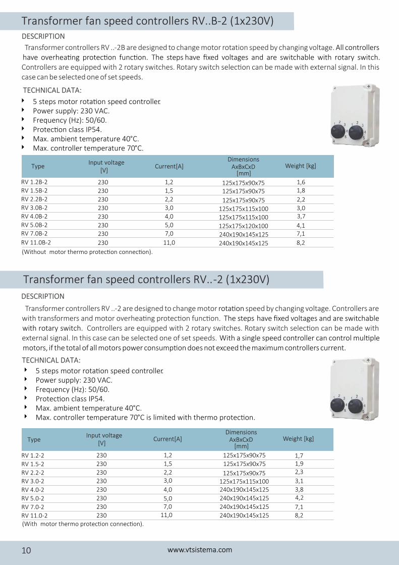
Transformer controllers RV ..- 2B are designed to change motor rotation speed by changing voltage. All controllers have overhea�ng protec�on func�on. The steps have fixed voltages and are switchable with rotary switch.Controllers are equipped with 2 rotary switches. Rotary switch selec�on can be made with external signal. In this case can be selected one of set speeds.
(Without motor thermo protec�on connec�on).
TECHNICAL DATA:
DESCRIPTION
Transformer fan speed controllers RV.. -2 (1x230V)
Transformer controllers RV ..- 2 are designed to change motor speed by changing voltage. Controllers are rota�onwith transformers and motor overhea�ng protec�on func�on. The steps h ave fixed voltages and are switchable with rotary switch. Controllers are equipped with 2 rotary switches. Rotary switch selec�on can be made with external signal. In this case can be selected one of set speeds. With a single speed controller can control mul�ple motors, if the total of all motors power consump�on does not exceed the maximum controllers current.
4 5 steps motor rota�on speed controller. 4 Power supply: 230 VAC. 4 Frequency (Hz): 50/60.4 Protec�on class IP54. 4 Max. ambient temperature 40°C.4 Max. controller temperature 70°C is limited with thermo protec�on.
(With motor thermo protec�on connec�on).
RV 3.0-2 230 3,0
RV 4.0-2 230 4,0
RV 5.0-2 230 5,0
RV 7.0-2 230 7,0
RV 11.0-2 230 11,0
RV 1.2-2 230 1,2
RV 1.5-2 230 1,5
RV 2.2-2 230 2,2
125x175x115x100240x190x145x125
240x190x145x125
240x190x145x125
240x190x145x125
125x175x90x75
125x175x90x75
125x175x90x75
1,71,92,3
3,1
3,84,2
7,18,2
TECHNICAL DATA:
DESCRIPTION
4 5 steps motor rota�on speed controller. 4 Power supply: 230 VAC. 4 Frequency (Hz): 50/60.4 Protec�on class IP54. 4 Max. ambient temperature 40°C.4 Max. controller temperature 70°C.
Transformer fan speed controllers RV..B-2 (1x230V)
www.vtsistema.com10
Type Current[A] Weight [kg]Input voltage [V]
Dimensions AxBxCxD
[mm]
RV 1.2B-2 230 1,2
RV 1.5B-2 230 1,5
RV 2.2B-2 230 2,2
RV 3.0B-2 230 3,0
RV 4.0B-2 230 4,0
RV 5.0B-2 230 5,0
RV 7.0B-2 230 7,0
RV 11.0B-2 230 11,0
125x175x90x75125x175x90x75
125x175x90x75
125x175x115x100
125x175x115x100
125x175x120x100
240x190x145x125
240x190x145x125
1,61,8
2,2
3,03,7
4,17,1
8,2
Type Current[A] Weight [kg]Input voltage [V]
Dimensions AxBxCxD
[mm]
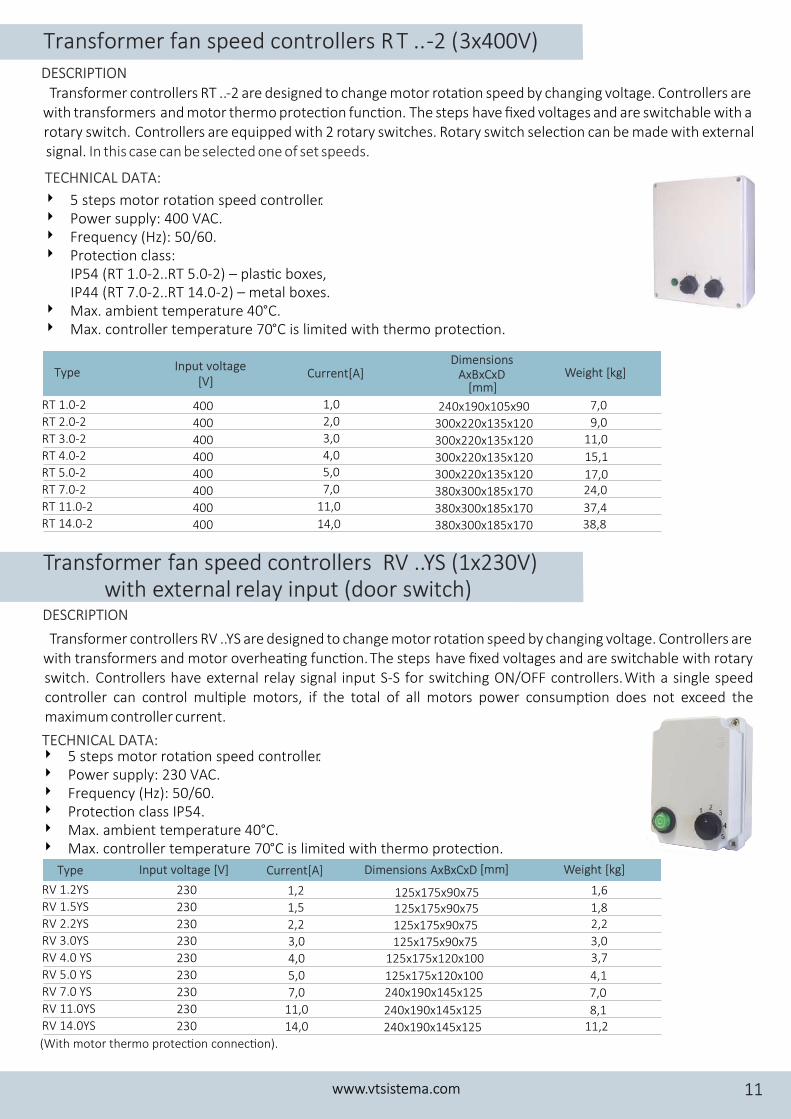
Transformer controllers RT ..-2 are designed to change motor rota�on speed by changing voltage. Controllers are with transformers and motor thermo protec�on func�on. The steps have fixed voltages and are switchable with a rotary switch. Controllers are equipped with 2 rotary switches. Rotary switch selec�on can be made with external signal. In this case can be selected one of set speeds.
4 5 steps motor rota�on speed controller. 4 Power supply: 400 VAC. 4 Frequency (Hz): 50/60.4 Protec�on class:
IP54 (RT 1.0-2..RT 5.0-2) – plas�c boxes,IP44 (RT 7.0-2..RT 14.0-2) – metal boxes.
4 Max. ambient temperature 40°C.4 Max. controller temperature 70°C is limited with thermo protec�on.
RT 1.0-2 400 1,0 240x190x105x90RT 2.0-2 400 2,0 300x220x135x120RT 3.0-2 400 3,0 300x220x135x120RT 4.0-2 400 4,0 300x220x135x120RT 5.0-2 400 5,0 300x220x135x120RT 7.0-2 400 7,0 380x300x185x170RT 11.0-2 400 11,0 380x300x185x170RT 14.0-2 400 14,0 380x300x185x170
7,0
9,0
11,0
15,1
17,024,0
37,438,8
TECHNICAL DATA:
DESCRIPTION
Transformer fan speed controllers RV ..YS (1x230V) with external r elay input (door switch)
Transformer controllers RV ..YS are designed to change motor rota�on speed by changing voltage. Controllers are with transformers and motor overhea�ng func�on.The steps have fixed voltages and are switchable with rotary swit ern l r With a single speed ch. Controllers have ext a elay signal input S-S for switching ON/OFF controllers. controller can control mul�ple motors, if the total of all motors power consump�on does not exceed the maximum controller current.
4 5 steps motor rota�on speed controller. 4 Power supply: 230 VAC. 4 Frequency (Hz): 50/60.4 Protec�on class IP54. 4 Max. ambient temperature 40°C.4 Max. controller temperature 70°C is limited with thermo protec�on.
Type Input voltage [V] Current[A] Weight [kg]Dimensions AxBxCxD [mm]
(With motor thermo protec�on connec�on).
1,6
1,82,2
3,0
3,7
4,1
7,0
8,111,2
RV 1.2YS 230 1,2RV 1.5YS 230 1,5RV 2.2YS 230 2,2RV 3.0YS 230 3,0RV 4.0 YS 230 4,0RV 5.0 YS 230 5,0RV 7.0 YS 230 7,0RV 11.0YS 230 11,0RV 14.0YS 230 14,0
125x175x90x75
125x175x120x100
240x190x145x125
240x190x145x125
240x190x145x125
125x175x90x75
125x175x90x75
125x175x90x75
125x175x120x100
TECHNICAL DATA:
DESCRIPTION
Transformer fan speed controllers R T .. -2 (3x400V)
www.vtsistema.com 11
Type Current[A] Weight [kg]Input voltage [V]
Dimensions AxBxCxD
[mm]
Transformer speed controllers RT ..YS (3x400V) with external relay input (door switch)
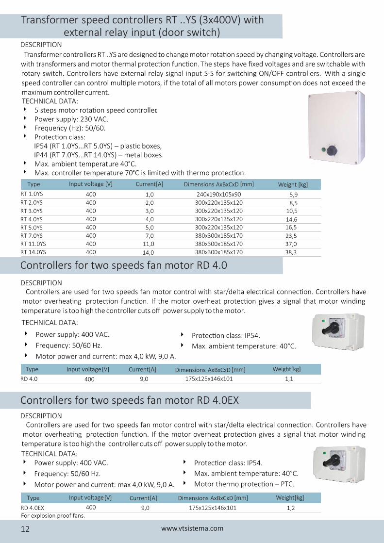
Transformer controllers RT ..YS are designed to change motor rota�on speed by changing voltage. Controllers are with transformers and motor thermal protec�on func�on.The steps have fixed voltages and are switchable with rotary swit ern l r With a single ch. Controllers have ext a elay signal input S-S for switching ON/OFF controllers. speed controller can control mul�ple motors, if the total of all motors power consump�on does not exceed the maximum controller current.
4 5 steps motor rota�on speed controller. 4 Power supply: 230 VAC. 4 Frequency (Hz): 50/60.4 Protec�on class:
IP54 (RT 1.0YS...RT 5.0YS) – plas�c boxes,IP44 (RT 7.0YS...RT 14.0YS) – metal boxes.
4 Max. ambient temperature 40°C.4 Max. controller temperature 70°C is limited with thermo protec�on.
TECHNICAL DATA:
DESCRIPTION
Type Input voltage [V] Current[A] Weight [kg]Dimensions AxBxCxD [mm]
RT 3.0YS 400 3,0
RT 4.0YS 400 4,0
RT 5.0YS 400 5,0
RT 7.0YS 400 7,0RT 11.0YS 400 11,0
RT 14.0YS 400 14,0
RT 1.0YS 400 1,0RT 2.0YS 400 2,0
300x220x135x120
300x220x135x120
300x220x135x120
380x300x185x170
380x300x185x170
380x300x185x170
240x190x105x90
300x220x135x120
10,5
14,616,5
23,5
37,0
38,3
5,9
8,5
Controllers are used or two speeds fan motor control with star/delta electrical connec�on. Controllers have f motor overhea�ng protec�on func�on. If the motor overheat pr a signal that motor winding otec�on gives t rature is too high the contr er supply to the mot . empe oller cuts off pow or
4 Power supply: 400 VAC.
4 Frequency: 50/60 Hz.
4 Motor power and current: max 4,0 kW, 9,0 A.
4 Protec�on class: IP54.
4 Max. ambient temperature: 40°C.
RD 4.0 400 9,0 175x125x146x101
Type Current[A]Input voltage [V] Dimensions AxBxCxD [mm] Weight[kg]
1,1
TECHNICAL DATA:
DESCRIPTION
Controllers for two speeds fan motor RD 4.0EX
Controllers are used or two speeds fan motor control with star/delta electrical connec�on. Controllers have f motor overhea�ng protec�on func�on. If the motor overheat pr a signal that motor winding otec�on gives t rature is too high the contr er supply to the mot . empe oller cuts off pow or
For explosion proof fans.RD 4.0EX 400 9,0
Type Current[A]Input voltage [V] Dimensions AxBxCxD [mm] Weight[kg]
175x125x146x101 1,2
4 Power supply: 400 VAC.
4 Frequency: 50/60 Hz.
4 Motor power and current: max 4,0 kW, 9,0 A.
4 Protec�on class: IP54.
4 Max. ambient temperature: 40°C.
4 Motor thermo protec�on – PTC.
TECHNICAL DATA:
DESCRIPTION
Controllers for two speeds fan motor RD 4.0
www.vtsistema.com12
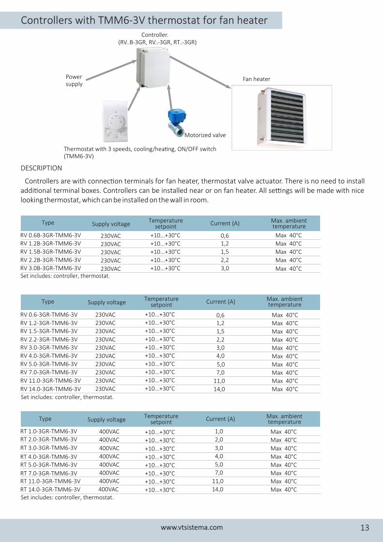
Controllers with TMM6-3V thermostat for fan heaterController.
(RV..B-3GR, RV..-3GR, RT..-3GR)
Power supply
Fan heater
Thermostat with 3 speeds, cooling/hea�ng, ON/OFF switch (TMM6-3V)
Motorized valve
Set lude : controller, thermostat.inc s
Set includes: controller, thermostat.
Set includes: controller, thermostat.
Controllers are with connec�on terminals for fan heater, thermostat valve actuator. There is no need to install addi�onal terminal boxes. Controllers can be installed near or on fan heater. All se�ngs will be made with nice looking thermostat, which can be installed on the wall in room.
Type Supply voltage Current (A) Temperature setpoint
Max. ambient temperature
230VAC 0,6RV 1.2B-3GR-TMM6-3V 230VAC 1,2
RV 1.5B-3GR-TMM6-3V 230VAC 1,5
RV 2.2B-3GR-TMM6-3V 230VAC 2,2
RV 3.0B-3GR-TMM6-3V 230VAC 3,0
+10...+30°C Max 40°C
+10...+30°C Max 40°C
+10...+30°C Max 40°C
+10...+30°C Max 40°C
+10...+30°C Max 40°C
RV 0.6B-3GR-TMM6-3V
DESCRIPTION
www.vtsistema.com 13
RV 0.6-3GR-TMM6-3V
RV 1.2-3GR-TMM6-3VRV 1.5-3GR-TMM6-3V
RV 2.2-3GR-TMM6-3VRV 3.0-3GR-TMM6-3V
RV 4.0-3GR-TMM6-3V
RV 5.0-3GR-TMM6-3V
RV 7.0-3GR-TMM6-3V
RV 11.0-3GR-TMM6-3V
RV 14.0-3GR-TMM6-3V
230VAC
230VAC
230VAC
230VAC
230VAC
230VAC
230VAC
230VAC
230VAC
230VAC
0,61,2
1,5
2,2
3,0
4,0
5,07,0
11,0
14,0
Max 40°C
Max 40°C
Max 40°C
Max 40°C
Max 40°C
Max 40°C
Max 40°C
Max 40°C
Max 40°C
+10...+30°C
+10...+30°C
+10...+30°C
+10...+30°C
+10...+30°C
+10...+30°C
+10...+30°C
+10...+30°C
+10...+30°C
+10...+30°C Max 40°C
RT 1.0-3GR-TMM6-3V 400VACRT 2.0-3GR-TMM6-3V 400VAC
+10...+30°C
+10...+30°CRT 3.0-3GR-TMM6-3V 400VAC
RT 4.0-3GR-TMM6-3V 400VAC
RT 5.0-3GR-TMM6-3V 400VAC
RT 7.0-3GR-TMM6-3V 400VAC
RT 11.0-3GR-TMM6-3V 400VAC
RT 14.0-3GR-TMM6-3V 400VAC
1,0
2,0
3,0
4,0
5,0
7,0
11,0
14,0
+10...+30°C
+10...+30°C
+10...+30°C
+10...+30°C
+10...+30°C
+10...+30°C
Max 40°C
Max 40°C
Max 40°C
Max 40°C
Max 40°C
Max 40°C
Max 40°C
Max 40°C
Type Supply voltage Current (A) Temperature setpoint
Max. ambient temperature
Type Supply voltage Current (A) Temperature setpoint
Max. ambient temperature
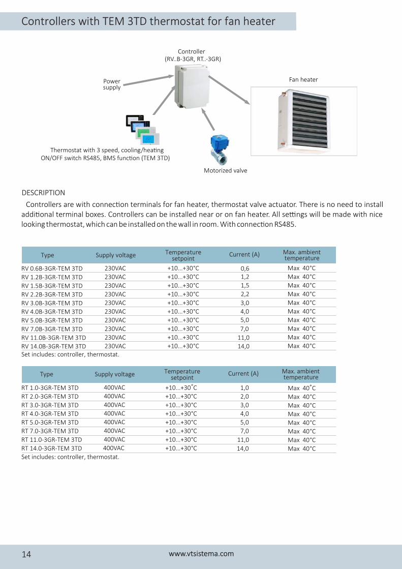
Controller (RV..B-3GR, RT..-3GR)
Power supply
Fan heater
Thermostat with 3 speed, cooling/hea�ngON/OFF switch RS485, BMS func�on (TEM 3TD)
Motorized valve
Set includes: controller, thermostat.
Set includes: controller, thermostat.
Controllers are with connec�on terminals for fan heater, thermostat valve actuator. There is no need to install addi�onal terminal boxes. Controllers can be installed near or on fan heater. All se�ngs will be made with nice looking thermostat, which can be installed on the wall in room. With connec�on RS485.
RV 0.6B-3GR-TEM 3TD 0,6
RV 1.2B-3GR-TEM 3TD 1,2
RV 1.5B-3GR-TEM 3TD 1,5
RV 2.2B-3GR-TEM 3TD 2,2
RV 3.0B-3GR-TEM 3TD 3,0
RV 4.0B-3GR-TEM 3TD 4,0
RV 5.0B-3GR-TEM 3TD 5,0
RV 7.0B-3GR-TEM 3TD 7,0
RV 11.0B-3GR-TEM 3TD 11,0
RV 14.0B-3GR-TEM 3TD
230VAC
230VAC
230VAC
230VAC
230VAC
230VAC
230VAC
230VAC
230VAC
230VAC 14,0
Max 40°C
Max 40°C
Max 40°C
Max 40°C
Max 40°C
Max 40°C
Max 40°C
Max 40°C
Max 40°C
+10...+30°C
+10...+30°C
+10...+30°C
+10...+30°C
+10...+30°C
+10...+30°C
+10...+30°C
+10...+30°C
+10...+30°C
+10...+30°C Max 40°C
DESCRIPTION
Controllers with TEM 3TD thermostat for fan heater
www.vtsistema.com14
Type Supply voltage Current (A) Temperature setpoint
Max. ambient temperature
Type Supply voltage Current (A) Temperature setpoint
Max. ambient temperature
RT 1.0-3GR-TEM 3TD 400VAC 1,0
RT 2.0-3GR-TEM 3TD 400VAC 2,0
RT 3.0-3GR-TEM 3TD 400VAC 3,0
RT 4.0-3GR-TEM 3TD 400VAC 4,0
RT 5.0-3GR-TEM 3TD 400VAC 5,0
RT 7.0-3GR-TEM 3TD 400VAC 7,0
RT 11.0-3GR-TEM 3TD 400VAC 11,0
RT 14.0-3GR-TEM 3TD 400VAC 14,0
+10...+30 C Max 40 C+10...+30°C Max 40°C+10...+30°C Max 40°C+10...+30°C Max 40°C+10...+30°C Max 40°C+10...+30°C Max 40°C+10...+30°C Max 40°C+10...+30°C Max 40°C
°°
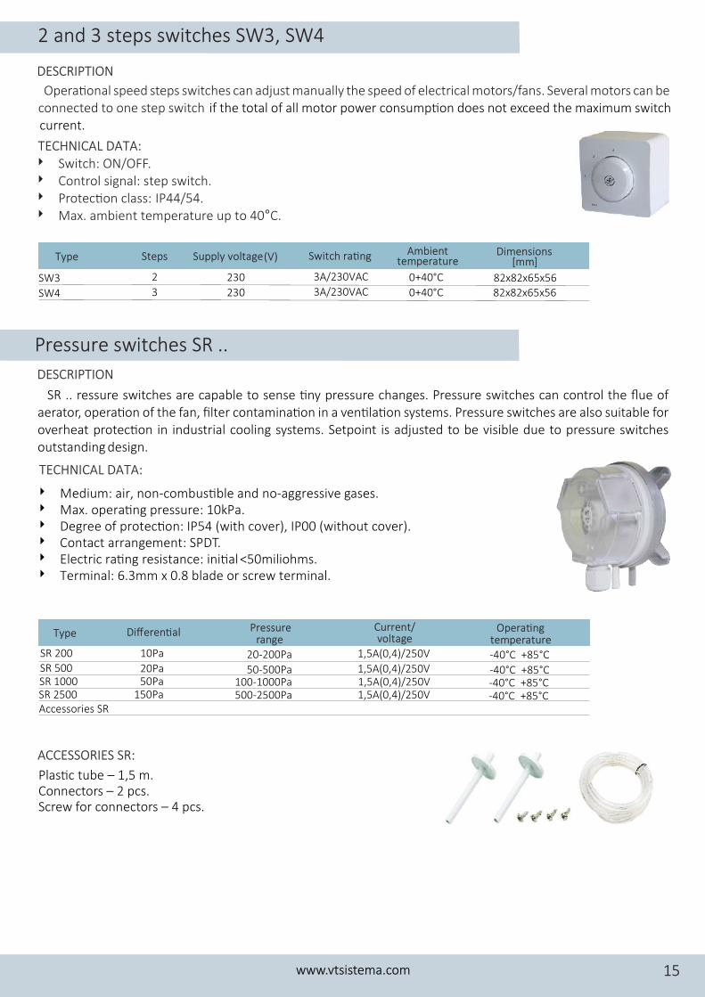
Pressure switches SR ..
SR .. ressure switches are capable to sense �ny pressure changes. Pressure switches can control the flue of aerator, opera�on of the fan, filter contamina�on in a ven�la�on systems. Pressure switches are also suitable for overheat protec�on in industrial cooling systems. Setpoint is adjusted to be visible due to pressure switches outstanding design.
4 Medium: air, non-combus�ble and no-aggressive gases.4 Max. opera�ng pressure: 10kPa.4 Degree of protec�on: IP54 (with cover), IP00 (without cover).4 Contact arrangement: SPDT.4 Electric ra�ng resistance: ini�al <50miliohms.4 Terminal: 6.3mm x 0.8 blade or screw terminal.
Type Differen�al Pressure range
SR 200 10Pa 20-200PaSR 500 20Pa 50-500Pa
Accessories SR
SR 1000SR 2500
50Pa150Pa
100-1000Pa500-2500Pa
Current/ voltage
1,5A(0,4)/250V
1,5A(0,4)/250V1,5A(0,4)/250V1,5A(0,4)/250V
Opera�ng temperature
-40°C +85°C
-40°C +85°C-40°C +85°C-40°C +85°C
TECHNICAL DATA:
Plas�c tube – 1,5 m.Connectors – 2 pcs.Screw for connectors – 4 pcs.
ACCESSORIES SR:
Opera�onal speed steps switches can adjust manually the speed of electrical motors/fans. Several motors can be connected to one step switch if the total of all motor power consump�on does not exceed the maximum switch current.
4 Switch: ON/OFF.4 Control signal: step switch. 4 Protec�on class: IP44/54.4 Max. ambient temperature up to 40°C.
SW4 3SW3 2
Type Steps
3A/230VAC
3A/230VAC
Switch ra�ng
230
230
Supply voltage (V)
0+40°C
0+40°C
Ambient temperature
82x82x65x5682x82x65x56
Dimensions [mm]
TECHNICAL DATA:
DESCRIPTION
DESCRIPTION
2 and 3 steps switches SW3, SW4
www.vtsistema.com 15
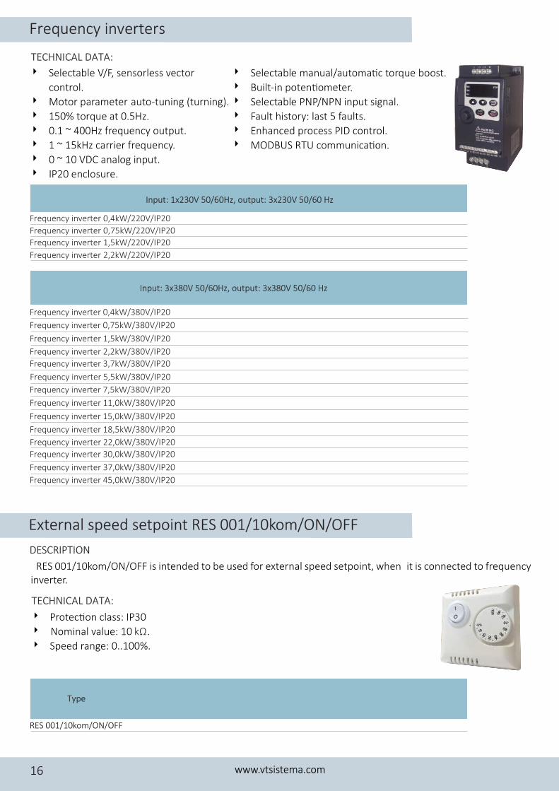
4 Selectabl manual/a toma�c t r u b oe u o q e o st.
4 Built-in poten�omet r.e
4 Selectabl PNP/NPN p te in u signal.
4 Fault histo y: last 5 faults.r
4 Enhanced process PID co trol.n
4 MODBUS RTU communica�on.
TECHNICAL DATA:
4 Selectable V/F, sensorless vector
control.
4 M to ao r p rameter auto-tuning (turning).
4 1 o q e50% t r u at 0.5 z.H
4 0 r.1 ~ 400Hz f equency output.
4 1 5 r ~ 1 kHz ca rier fre u nq e cy.
4 0 0 n l ~ 1 VDC a a og i p t.n u
4 I 0 n su e.P2 e clo r
Input: 1x230V 50/60Hz, output: 3x230V 50/60 Hz
Frequency inverter 0,4kW/220V/IP20
Frequency inverter 0,75kW/220V/IP20
Frequency inverter 1,5kW/220V/IP20
Frequency inverter 2,2kW/220V/IP20
Input: 3x380V 50/60Hz, output: 3x380V 50/60 Hz
Frequency inverter 0,4kW/380V/IP20
Frequency inverter 0,75kW/380V/IP20
Frequency inverter 1,5kW/380V/IP20
Frequency inverter 2,2kW/380V/IP20
Frequency inverter 3,7kW/380V/IP20
Frequency inverter 5,5kW/380V/IP20
Frequency inverter 7,5kW/380V/IP20
Frequency inverter 11,0kW/380V/IP20
Frequency inverter 15,0kW/380V/IP20
Frequency inverter 18,5kW/380V/IP20
Frequency inverter 22,0kW/380V/IP20
Frequency inverter 30,0kW/380V/IP20
Frequency inverter 37,0kW/380V/IP20
Frequency inverter 45,0kW/380V/IP20
Type
RES 001/10kom/ON/OFF
TECHNICAL DATA:
External speed setpoint RES 001/10kom/ON/OFF
DESCRIPTION
RES 001/10kom/ON/OFF is intended to be used for external speed setpoint, when it is connected to frequency inverter.
4 Protec�on class: IP30
4 Nominal value: 10 . kΩ
4 Speed range: 0..100%.
Frequency inverters
www.vtsistema.com16
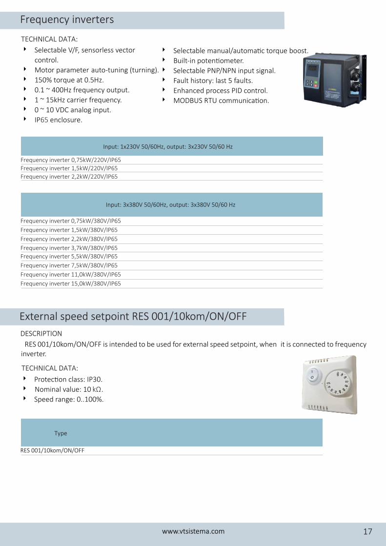
Frequency inverter 0,75kW/380V/IP65
Frequency inverter 1,5kW/380V/IP65
Frequency inverter 2,2kW/380V/IP65
Frequency inverter 3,7kW/380V/IP65
Frequency inverter 5,5kW/380V/IP65
Frequency inverter 7,5kW/380V/IP65
Frequency inverter 11,0kW/380V/IP65
Frequency inverter 15,0kW/380V/IP65
Type
RES 001/10kom/ON/OFF
TECHNICAL DATA:
External speed setpoint RES 001/10kom/ON/OFF
DESCRIPTION
RES 001/10kom/ON/OFF is intended to be used for external speed setpoint, when it is connected to frequency inverter.
4 Protec�on class: IP30.
4 Nominal value: 10 . kΩ
4 Speed range: 0..100%.
TECHNICAL DATA:
4 Selectabl manual/a toma�c t r u b oe u o q e o st.
4 Built-in poten�omet r.e
4 Selectabl PNP/NPN p te in u signal.
4 Fault histo y: last 5 faults.r
4 Enhanced process PID co trol.n
4 MODBUS RTU communica�on.
4 Selectable V/F, sensorless vector
control.
4 M to ao r p rameter auto-tuning (turning).
4 1 o q e50% t r u at 0.5 z.H
4 0 r.1 ~ 400Hz f equency output.
4 1 5 r ~ 1 kHz ca rier fre u nq e cy.
4 0 0 n l ~ 1 VDC a a og i p t.n u
4 I n su e.P e clo r65
Input: 3x380V 50/60Hz, output: 3x380V 50/60 Hz
Input: 1x230V 50/60Hz, output: 3x230V 50/60 Hz
Frequency inverter 0,75kW/220V/IP65
Frequency inverter 1,5kW/220V/IP65
Frequency inverter 2,2kW/220V/IP65
Frequency inverters
www.vtsistema.com 17
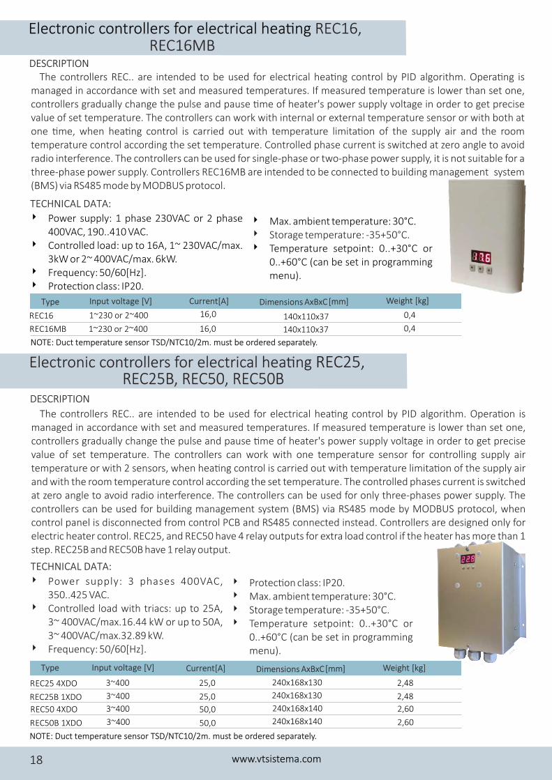
The controllers REC.. are intended to be used for electrical hea�ng control by PID algorithm. Opera�ng is managed in accordance with set and measured temperatures. If measured temperature is lower than set one, controllers gradually change the pulse and pause �me of heater's power supply voltage in order to get precise value of set temperature. The controllers can work with internal or external temperature sensor or with both at one �me, when hea�ng control is carried out with temperature limita�on of the supply air and the room temperature control according the set temperature. Controlled phase current is switched at zero angle to avoid radio interference. The controllers can be used for single-phase or two-phase power supply, it is not suitable for a three-phase power supply. Controllers REC16MB are intended to be connected to building management system (BMS) via RS485 mode by MODBUS protocol.
4 Power supply: 1 phase 230VAC or 2 phase 400VAC, 190..410 VAC.
4 Controlled load: up to 16A, 1~ 230VAC/max. 3kW or 2~ 400VAC/max. 6kW.
4 Frequency: 50/60[Hz].4 Protec�on class: IP20.
Type Input voltage [V] Current[A] Weight [kg]Dimensions AxBxC [mm]
REC16 1~230 or 2~400 16,0 140x110x37 0,4
REC16MB 16,0 140x110x37 0,41~230 or 2~400
TECHNICAL DATA:
REC16MB Electronic controllers for electrical hea�ng REC16,
DESCRIPTION
NOTE: uct emperature sensor TSD/NTC10/2m. must be ordered separately. D t
www.vtsistema.com18
4 Max. ambient temperature: 30°C.4 Storage temperature: -35+50°C.4 Temperature setpoint: 0..+30°C or
0..+60°C (can be set in programming menu).
The controllers REC.. are intended to be used for electrical hea�ng control by PID algorithm. Opera�on is managed in accordance with set and measured temperatures. If measured temperature is lower than set one, controllers gradually change the pulse and pause �me of heater's power supply voltage in order to get precise value of set temperature. The controllers can work with one temperature sensor for controlling supply air temperature or with 2 sensors, when hea�ng control is carried out with temperature limita�on of the supply air and with the room temperature control according the set temperature. The controlled phases current is switched at zero angle to avoid radio interference. The controllers can be used for only three-phases power supply. The controllers can be used for building management system (BMS) via RS485 mode by MODBUS protocol, when control panel is disconnected from control PCB and RS485 connected instead. Controllers are designed only for electric heater control. REC25, and REC50 have 4 relay outputs for extra load control if the heater has more than 1 step. REC25B and REC50B have 1 relay output.
4 Power supply: 3 phases 400VAC, 350..425 VAC.
4 Controlled load with triacs: up to 25A, 3~ 400VAC/max.16.44 kW or up to 50A, 3~ 400VAC/max.32.89 kW.
4 Frequency: 50/60[Hz].
TECHNICAL DATA:
Electronic controllers for electrical hea�ng REC25, REC25B, REC50, REC50B
DESCRIPTION
REC25 4XDO 3~400 25,0
REC25B 1XDO 25,0
2,48
2,483~400
REC50 4XDO 3~400 50,0
REC50B 1XDO 50,0
240x168x130
240x168x130
240x168x140
240x168x140
2,60
2,603~400
Type Input voltage [V] Current[A] Weight [kg]Dimensions AxBxC [mm]
4 Protec�on class: IP20.4 Max. ambient temperature: 30°C.4 Storage temperature: -35+50°C.4 Temperature setpoint: 0..+30°C or
0..+60°C (can be set in programming menu).
NOTE: uct emperature sensor TSD/NTC10/2m. must be ordered separately. D t
Electric circular duct heaters/preheaters for ven�la�on systems
www.vtsistema.com 19
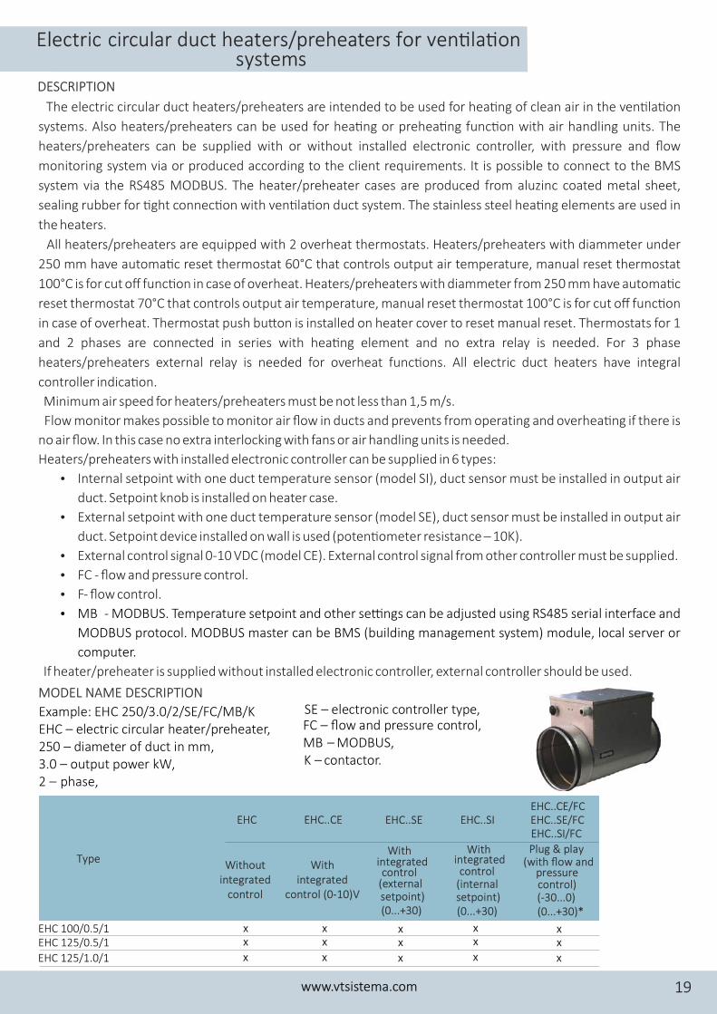
The electric circular duct heaters/preheaters are intended to be used for hea�ng of clean air in the ven�la�on
systems. Also heaters/preheaters can be used for hea�ng or prehea�ng func�on with air handling units. The
heaters/preheaters can be supplied with or without installed electronic controller, with pressure and flow
monitoring system via or produced according to the client requirements. It is possible to connect to the BMS
system via the RS485 MODBUS. The heater/preheater cases are produced from aluzinc coated metal sheet,
sealing rubber for �ght connec�on with ven�la�on duct system. The stainless steel hea�ng elements are used in
the heaters.
All heaters/preheaters are equipped with 2 overheat thermostats. Heaters/preheaters with diammeter under
250 mm have automa�c reset thermostat 60°C that controls output air temperature, manual reset thermostat
100°C is for cut off func�on in case of overheat. Heaters/preheaters with diammeter from 250 mm have automa�c
reset thermostat 70°C that controls output air temperature, manual reset thermostat 100°C is for cut off func�on
in case of overheat. Thermostat push bu�on is installed on heater cover to reset manual reset. Thermostats for 1
and 2 phases are connected in series with hea�ng element and no extra relay is needed. For 3 phase
heaters/preheaters external relay is needed for overheat func�ons. All electric duct heaters have integral
controller indica�on.
Minimum air speed for heaters/preheaters must be not less than 1,5 m/s.
Flow monitor makes possible to monitor air flow in ducts and prevents from operating and overhea�ng if there is
no air flow. In this case no extra interlocking with fans or air handling units is needed.
Heaters/preheaters with installed electronic controller can be supplied in 6 types:
� Internal setpoint with one duct temperature sensor (model SI), duct sensor must be installed in output air
duct. Setpoint knob is installed on heater case.
� External setpoint with one duct temperature sensor (model SE), duct sensor must be installed in output air
duct. Setpoint device installed on wall is used (poten�ometer resistance – 10K).
� External control signal 0-10 VDC (model CE). External control signal from other controller must be supplied.
� FC - flow and pressure control.
� F- flow control.
� MB - MODBUS. Temperature setpoint and other se�ngs can be adjusted using RS485 serial interface and
MODBUS protocol. MODBUS master can be BMS (building management system) module, local server or
computer.
If heater/preheater is supplied without installed electronic controller, external controller should be used.
Example: EHC 250/3.0/2/SE/FC/MB/KEHC – electric circular heater/preheater,250 – diameter of duct in mm, 3.0 – output power kW,2 – phase,
MODEL NAME DESCRIPTION
Type
EHC..CE EHC..SE EHC..SI
Without integrated
control
With integrated
control (0-10)V
EHCEHC..CE/FCEHC..SE/FCEHC..SI/FC
With integrated control
(external setpoint) (0...+30)
With integrated control
(internal setpoint) (0...+30)
Plug & play (with flow and
pressure control)(-30...0)(0...+30)*
EHC 100/0.5/1EHC 125/0.5/1
EHC 125/1.0/1
x
DESCRIPTION
FC – flow and pressure control,MB – MODBUS,K – contactor.
x
x
xx
x
xx
x
xx
x
xx
x
SE – electronic controller type,
EHC 160/1.0/1EHC 160/1.5/1
EHC 160/2.0/1
EHC 160/3.0/1EHC 160/3.0/2
EHC 160/4.5/2
EHC 250/1.5/1
EHC 250/2.0/1
EHC 250/3.0/1
EHC 250/3.0/2
EHC 250/4.5/2
EHC 250/6.0/2
EHC 250/6.0/3
EHC 250/9.0/3
EHC 315/2.0/1
EHC 315/3.0/1
EHC 315/3.0/2
EHC 315/4.5/2EHC 315/6.0/2
EHC 315/6.0/3
EHC 315/9.0/3
EHC 315/12.0/3
EHC 400/3.0/1
EHC 400/3.0/2EHC 400/4.5/2
EHC 200/1.5/1
EHC 200/2.0/1
EHC 200/3.0/1
EHC 200/3.0/2
EHC 200/4.5/2
EHC 200/6.0/2
EHC 200/6.0/3
EHC 200/9.0/3EHC 250/1.0/1
EHC 200/1.0/1
EHC 400/9.0/3
EHC 400/12.0/3
EHC 400/15.0/3
EHC 400/6.0/2
EHC 400/6.0/3
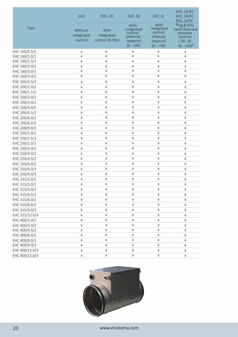
EHC 160/0.5/1
Type Without
integrated control
With integrated
control (0-10)V
With integrated control
(external setpoint) (0...+30)
With integrated control
(internal setpoint) (0...+30)
Plug & play (with flow and
pressure control)(-30...0)(0...+30)*
www.vtsistema.com20
EHC..CE EHC..SE EHC..SIEHCEHC..CE/FCEHC..SE/FCEHC..SI/FC
xx
xxx
x
x
xx
x
x
x
x
x
x
xx
x
x
x
xx
x
x
x
x
x
x
x
x
x
x
x
x
xx
xxx
x
x
xx
xxx
x
x
xx
x
x
x
x
x
x
xx
x
x
x
xx
x
x
x
x
x
x
x
x
x
x
x
x
xx
xxx
x
x
xx
xxx
x
x
xx
x
x
x
x
x
x
xx
x
x
x
xx
x
x
x
x
x
x
x
x
x
x
x
x
xx
xxx
x
x
xx
xxx
x
x
xx
x
x
x
x
x
x
xx
x
x
x
xx
x
x
x
x
x
x
x
x
x
x
x
x
xx
xxx
x
x
xx
xxx
x
x
xx
x
x
x
x
x
x
xx
x
x
x
xx
x
x
x
x
x
x
x
x
x
x
x
x
xx
xxx
x
x
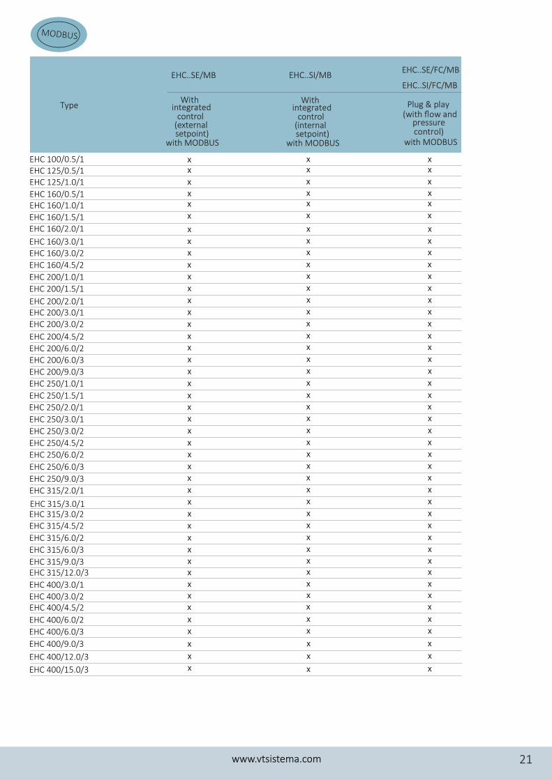
Type
EHC..SI/MBEHC..SE/MBEHC..SE/FC/MB
EHC..SI/FC/MB
Plug & play (with flow and
pressure control)
with MODBUS
With integrated
setpoint)
control (external
with MODBUS
With integrated
setpoint)
control (internal
with MODBUS
MODBUS
www.vtsistema.com 21
xx
xxx
x
x
xx
x
x
x
x
x
x
xx
x
x
x
xx
x
x
x
x
x
x
x
x
x
x
x
x
xx
xxx
x
x
xx
xxx
x
x
xx
x
x
x
x
x
x
xx
x
x
x
xx
x
x
x
x
x
x
x
x
x
x
x
x
xx
xxx
x
x
Type
EHC 160/1.0/1
EHC 160/1.5/1EHC 160/2.0/1
EHC 160/3.0/1EHC 160/3.0/2
EHC 160/4.5/2
EHC 250/1.5/1
EHC 250/2.0/1
EHC 250/3.0/1
EHC 250/3.0/2
EHC 250/4.5/2
EHC 250/6.0/2
EHC 250/6.0/3
EHC 250/9.0/3
EHC 315/2.0/1
EHC 315/3.0/1EHC 315/3.0/2
EHC 315/4.5/2
EHC 315/6.0/2
EHC 315/6.0/3
EHC 315/9.0/3EHC 315/12.0/3
EHC 400/3.0/1
EHC 400/3.0/2EHC 400/4.5/2
EHC 200/1.5/1
EHC 200/2.0/1EHC 200/3.0/1
EHC 200/3.0/2
EHC 200/4.5/2
EHC 200/6.0/2
EHC 200/6.0/3
EHC 200/9.0/3
EHC 250/1.0/1
EHC 200/1.0/1
EHC 125/0.5/1EHC 125/1.0/1
EHC 160/0.5/1
EHC 100/0.5/1
EHC 400/9.0/3
EHC 400/12.0/3
EHC 400/15.0/3
EHC 400/6.0/2
EHC 400/6.0/3
x
x
x
xx
xxx
x
x
xx
x
x
x
x
x
x
xx
x
x
x
xx
x
x
x
x
x
x
x
x
x
x
x
x
xx
xxx
x
x
x
x
x
x
x
x
Type
NOTE: external temperature setpoint RES 001, RES 002/NTC are needed for EHC..SE, SE/FC modifica�on.
*NOTE: heaters/preheaters with SE/FC modifica�on have a scale (0...+30); heaters/preheaters with SI/FC
NOTE: heaters/preheaters with integrate control system EHC...SE, EHC...SI – temperatureduct sensor L-2.0 m
NOTE: to specify a temperature scale (-30...0) or (0..+30) in order. modifica�on have a scale (-30...0) or (0...+30).
included.
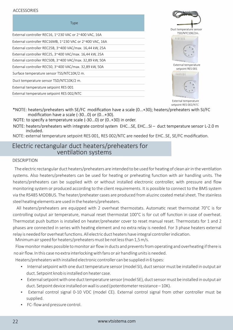
External controller REC16, 1~230 VAC or 2~400 VAC, 16A
Surface temperature sensor TSS/NTC10K/2 m.
Duct temperature sensor TSD/NTC10K/2 m.
External controller REC16MB, 1~230 VAC or 2~400 VAC, 16A
External controller REC25B, 3~400 VAC/max. 16,44 kW, 25A
External controller REC25, 3~400 VAC/max. 16,44 kW, 25A
External controller REC50B, 3~400 VAC/max. 32,89 kW, 50A
External controller REC50, 3~400 VAC/max. 32,89 kW, 50A
External temperature setpoint RES 001
External temperature setpoint RES 002/NTC
External temperature setpoint RES 001
Duct temperature sensor TSD/NTC10K/2m.
External temperature setpoint RES 002/NTC
ACCESSORIES
The electric rectangular duct heaters/preheaters are intended to be used for hea�ng of clean air in the ven�la�on
systems. Also heaters/preheaters can be used for hea�ng or prehea�ng func�on with air handling units. The
heaters/preheaters can be supplied with or without installed electronic controller, with pressure and flow
monitoring system or produced according to the client requirements. It is possible to connect to the BMS system
via the RS485 MODBUS. The heater/preheater cases are produced from aluzinc coated metal sheet. The stainless
steel hea�ng elements are used in the heaters/preheaters.
All heaters/preheaters are equipped with 2 overheat thermostats. Automa�c reset thermostat 70°C is for
controlling output air temperature, manual reset thermostat 100°C is for cut off func�on in case of overheat.
Thermostat push bu�on is installed on heater/preheater cover to reset manual reset. Thermostats for 1 and 2
phases are connected in series with hea�ng element and no extra relay is needed. For 3 phase heaters external
relay is needed for overheat func�ons. All electric duct heaters have integral controller indica�on. Minimum air speed for heaters/preheaters must be not less than 1,5 m/s.
Flow monitor makes possible to monitor air flow in ducts and prevents from operating and overhea�ng if there is
no air flow. In this case no extra interlocking with fans or air handling units is needed.
Heaters/preheaters with installed electronic controller can be supplied in 6 types:
� Internal setpoint with one duct temperature sensor (model SI), duct sensor must be installed in output air
duct. Setpoint knob is installed on heater case.
� External setpoint with one duct temperature sensor (model SE), duct sensor must be installed in output air
duct. Setpoint device installed on wall is used (poten�ometer resistance – 10K).
� External control signal 0-10 VDC (model CE). External control signal from other controller must be
supplied.
� FC- flow and pressure control.
DESCRIPTION
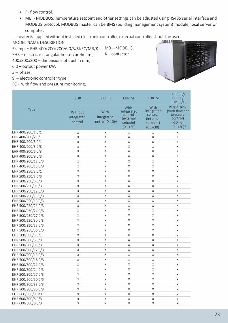
Electric rectangular duct heaters/preheaters for ven�la�on systems
www.vtsistema.com22
EHR 400/200/1.0/1EHR 400/200/2.0/1EHR 400/200/3.0/1
EHR 400/200/3.0/3
EHR 400/200/6.0/3
EHR 400/200/9.0/3
EHR 400/200/12.0/3
EHR 400/200/15.0/3
EHR 500/250/3.0/1
EHR 500/250/3.0/3
EHR 500/250/6.0/3EHR 500/250/9.0/3
EHR 500/250/12.0/3
EHR 500/250/15.0/3
EHR 500/250/18.0/3EHR 500/250/21.0/3
EHR 500/250/24.0/3
EHR 500/250/27.0/3
EHR 500/250/30.0/3
EHR 500/250/33.0/3
EHR 500/250/36.0/3
EHR 500/300/3.0/1
EHR 500/300/6.0/3
EHR 500/300/9.0/3
EHR 500/300/12.0/3
EHR 500/300/15.0/3
EHR 500/300/18.0/3
EHR 500/300/21.0/3
EHR 500/300/24.0/3
EHR 500/300/27.0/3
EHR 500/300/30.0/3
EHR 500/300/33.0/3
EHR 500/300/36.0/3
EHR 600/300/3.0/3EHR 600/300/6.0/3EHR 600/300/9.0/3
Type
EHR..CE EHR..SE EHR..SI
Without integrated
control
With
integrated
control (0-10)V
EHREHR..CE/FCEHR..SE/FCEHR..SI/FC
With integrated control
(external setpoint) (0...+30)
With integrated control
(internal setpoint) (0...+30)
Plug & play (with flow and
pressure control)(-30...0)(0...+30)*
23
xx
xxx
x
x
xx
x
x
x
x
x
x
xx
x
x
x
xx
x
x
x
x
x
x
x
x
x
x
x
x
x
xx
xxx
x
x
xx
x
x
x
x
x
x
xx
x
x
x
xx
x
x
x
x
x
x
x
x
x
x
x
x
xx
xx
xxx
x
x
xx
x
x
x
x
x
x
xx
x
x
x
xx
x
x
x
x
x
x
x
x
x
x
x
x
xx
xx
xxx
x
x
xx
x
x
x
x
x
x
xx
x
x
x
xx
x
x
x
x
x
x
x
x
x
x
x
x
xx
xx
xxx
x
x
xx
x
x
x
x
x
x
xx
x
x
x
xx
x
x
x
x
x
x
x
x
x
x
x
x
xx x
� F - flow control.
� MB - MODBUS. Temperature setpoint and other se�ngs can be adjusted using RS485 serial interface and
MODBUS protocol. MODBUS master can be BMS (building management system) module, local server or
computer.
If heater is supplied without installed electronic controller, external controller should be used.
MODEL NAME DESCRIPTION
Example: EHR 400x200x200/6.0/3/SI/FC/MB/K
EHR – electric rectangular heater/preheater,
400x200x200 – dimensions of duct in mm,
6.0 – output power kW,
3 – phase,
SI – electronic controller type,
FC – with flow and pressure monitoring,
MB – MODBUS,
K – contactor.
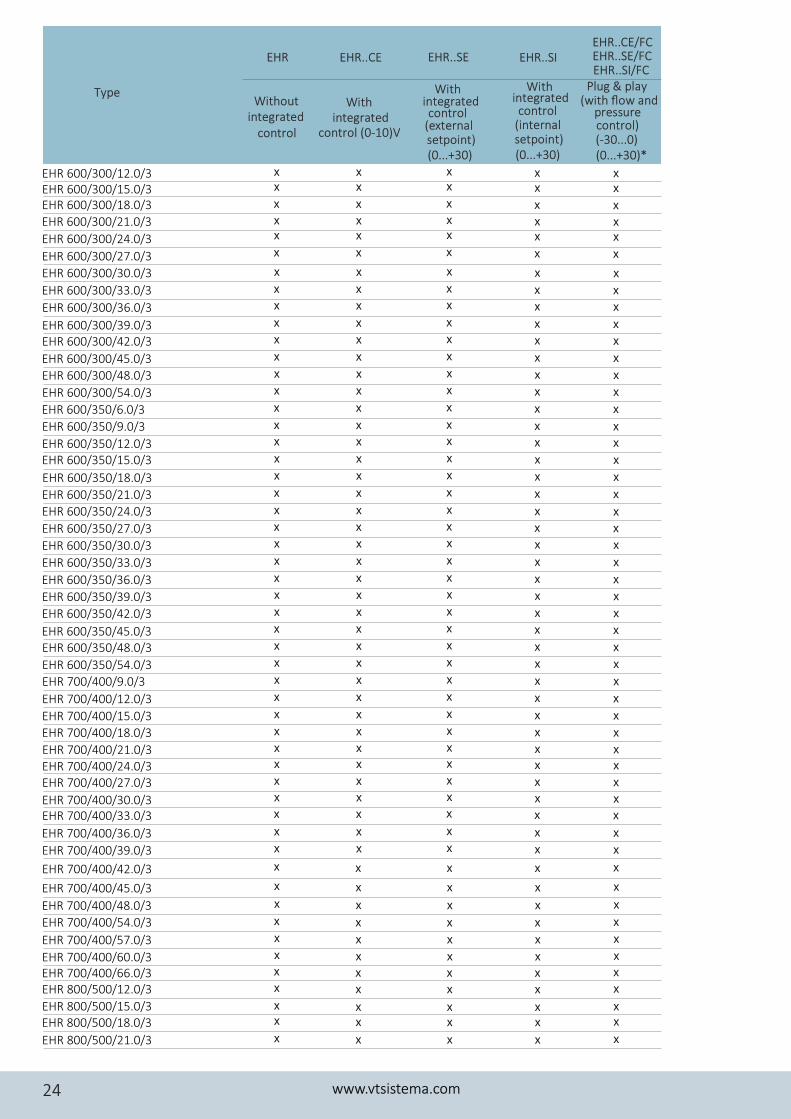
Type Without
integrated With
integrated control (0-10)Vcontrol
With integrated control
(external setpoint) (0...+30)
With integrated control
(internal setpoint) (0...+30)
Plug & play (with flow and
pressure control)(-30...0)(0...+30)*
www.vtsistema.com24
EHR..CE EHR..SE EHR..SIEHREHR..CE/FCEHR..SE/FCEHR..SI/FC
EHR 600/300/12.0/3EHR 600/300/15.0/3EHR 600/300/18.0/3
EHR 600/300/21.0/3
EHR 600/300/24.0/3
EHR 600/300/27.0/3
EHR 600/300/30.0/3
EHR 600/300/33.0/3
EHR 600/300/36.0/3
EHR 600/300/39.0/3EHR 600/300/42.0/3
EHR 600/300/45.0/3
EHR 600/300/48.0/3
EHR 600/300/54.0/3
EHR 600/350/6.0/3
EHR 600/350/9.0/3
EHR 600/350/12.0/3EHR 600/350/15.0/3
EHR 600/350/18.0/3
EHR 600/350/21.0/3
EHR 600/350/24.0/3
EHR 600/350/27.0/3
EHR 600/350/30.0/3
EHR 600/350/33.0/3
EHR 600/350/36.0/3
EHR 600/350/39.0/3
EHR 600/350/42.0/3
EHR 600/350/45.0/3EHR 600/350/48.0/3
EHR 600/350/54.0/3
EHR 700/400/9.0/3
EHR 700/400/12.0/3
EHR 700/400/15.0/3
EHR 700/400/18.0/3
EHR 700/400/21.0/3EHR 700/400/24.0/3EHR 700/400/27.0/3
EHR 700/400/30.0/3EHR 700/400/33.0/3
EHR 700/400/36.0/3
EHR 700/400/39.0/3
EHR 700/400/42.0/3
EHR 700/400/45.0/3
EHR 700/400/48.0/3
EHR 700/400/54.0/3
EHR 700/400/57.0/3
EHR 700/400/60.0/3EHR 700/400/66.0/3EHR 800/500/12.0/3
EHR 800/500/15.0/3EHR 800/500/18.0/3
EHR 800/500/21.0/3
xx
xxx
x
x
xx
x
x
x
x
x
x
xx
x
x
x
xx
x
x
x
x
x
x
x
x
x
x
x
x
xx
xxx
x
x
xx
xxx
x
x
xx
x
x
x
x
x
x
xx
x
x
x
xx
x
x
x
x
x
x
x
x
x
x
x
x
xx
xxx
x
x
x
x
x
x
x
xxx
xx
x
xx
xxx
x
x
xx
x
x
x
x
x
x
xx
x
x
x
xx
x
x
x
x
x
x
x
x
x
x
x
x
xx
xxx
x
x
x
x
x
x
x
xxx
xx
x
xx
xxx
x
x
xx
x
x
x
x
x
x
xx
x
x
x
xx
x
x
x
x
x
x
x
x
x
x
x
x
xx
xxx
x
x
x
x
x
x
x
xxx
xx
x
xx
xxx
x
x
xx
x
x
x
x
x
x
xx
x
x
x
xx
x
x
x
x
x
x
x
x
x
x
x
x
xx
xxx
x
x
x
x
x
x
x
xxx
xx
x
x
x
x
x
x
xxx
xx
x
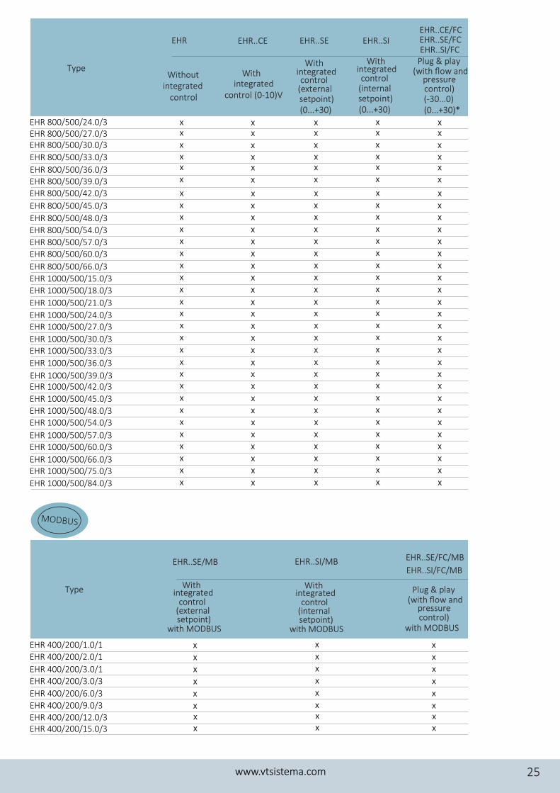
Type Without
integrated
With integrated
control (0-10)Vcontrol
With integrated control
(external setpoint) (0...+30)
With integrated control
(internal setpoint) (0...+30)
Plug & play (with flow and
pressure control)(-30...0)(0...+30)*
EHR 1000/500/84.0/3
EHR 800/500/24.0/3EHR 800/500/27.0/3EHR 800/500/30.0/3
EHR 800/500/33.0/3
EHR 800/500/36.0/3EHR 800/500/39.0/3
EHR 800/500/42.0/3
EHR 800/500/45.0/3
EHR 800/500/48.0/3
EHR 800/500/54.0/3
EHR 800/500/57.0/3EHR 800/500/60.0/3
EHR 800/500/66.0/3
EHR 1000/500/15.0/3
EHR 1000/500/18.0/3
EHR 1000/500/21.0/3
EHR 1000/500/24.0/3EHR 1000/500/27.0/3
EHR 1000/500/30.0/3
EHR 1000/500/33.0/3
EHR 1000/500/36.0/3
EHR 1000/500/39.0/3EHR 1000/500/42.0/3
EHR 1000/500/45.0/3
EHR 1000/500/48.0/3
EHR 1000/500/54.0/3
EHR 1000/500/57.0/3
EHR 1000/500/60.0/3
EHR 1000/500/66.0/3EHR 1000/500/75.0/3
Type
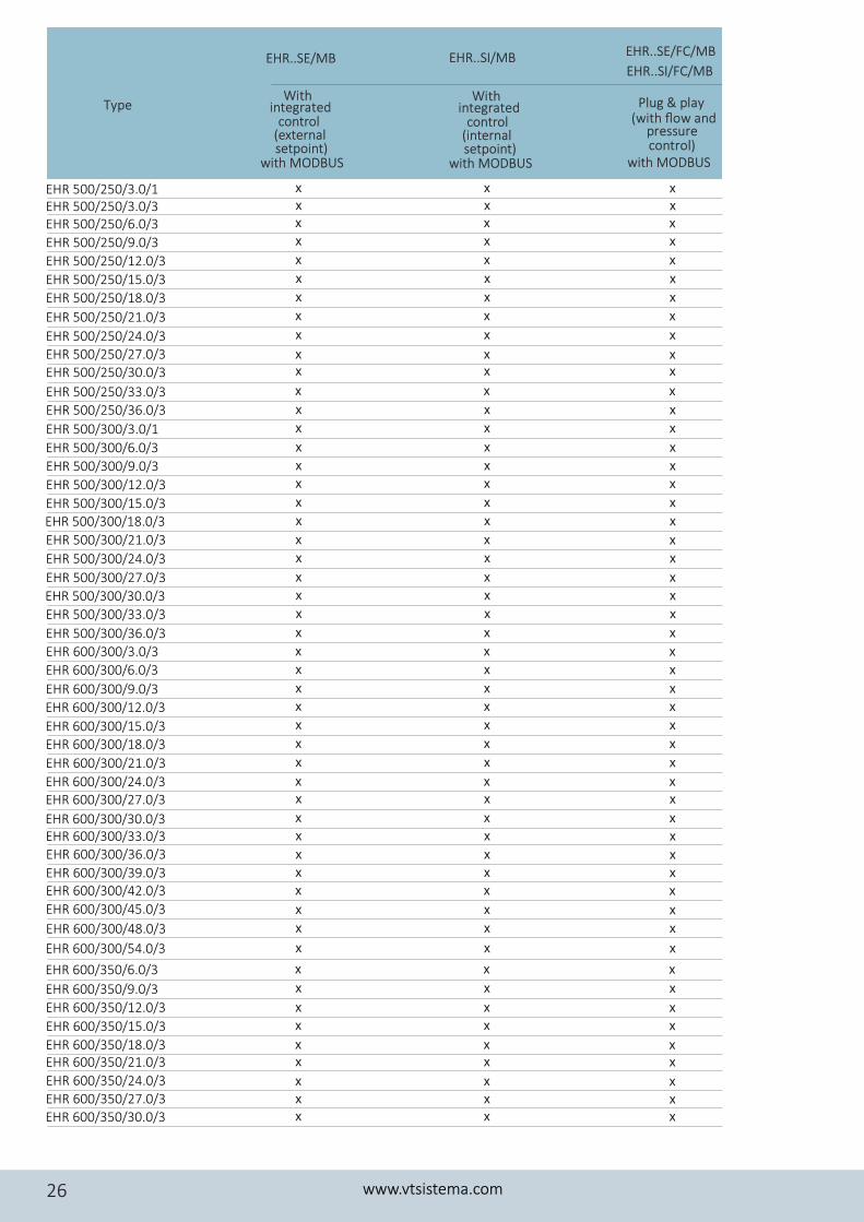
EHR..SI/MBEHR..SE/MB EHR..SE/FC/MB
EHR..SI/FC/MB
Plug & play (with flow and
pressure control)
with MODBUS
With integrated
setpoint)
control (external
with MODBUS
With integrated
setpoint)
control (internal
with MODBUS
MODBUS
www.vtsistema.com 25
EHR..CE EHR..SE EHR..SIEHREHR..CE/FCEHR..SE/FCEHR..SI/FC
xx
xxx
x
x
xx
x
x
x
x
x
x
xx
x
x
x
xx
x
x
x
x
x
x
x
x
x
xx
xxx
x
x
xx
x
x
x
x
x
x
xx
x
x
x
xx
x
x
x
x
x
x
x
x
x
xx
xxx
x
x
xx
x
x
x
x
x
x
xx
x
x
x
xx
x
x
x
x
x
x
x
x
x
xx
xxx
x
x
xx
x
x
x
x
x
x
xx
x
x
x
xx
x
x
x
x
x
x
x
x
x
xx
xxx
x
x
xx
x
x
x
x
x
x
xx
x
x
x
xx
x
x
x
x
x
x
x
x
x
EHR 400/200/1.0/1
EHR 400/200/2.0/1
EHR 400/200/3.0/1
EHR 400/200/3.0/3
EHR 400/200/6.0/3
EHR 400/200/9.0/3
EHR 400/200/12.0/3EHR 400/200/15.0/3
x
x
x
x
x
xxx
x
x
x
x
x
xxx
x
x
x
x
x
xxx
Plug & play (with flow and
pressure control)
with MODBUS
With integrated
setpoint)
control (external
with MODBUS
With integrated
setpoint)
control (internal
with MODBUS
Type
www.vtsistema.com26
EHR..SI/MBEHR..SE/MB EHR..SE/FC/MB
EHR..SI/FC/MB
EHR 500/250/3.0/1EHR 500/250/3.0/3EHR 500/250/6.0/3
EHR 500/250/9.0/3
EHR 500/250/12.0/3
EHR 500/250/15.0/3
EHR 500/250/18.0/3
EHR 500/250/21.0/3
EHR 500/250/24.0/3EHR 500/250/27.0/3EHR 500/250/30.0/3
EHR 500/250/33.0/3
EHR 500/250/36.0/3
EHR 500/300/3.0/1
EHR 500/300/6.0/3
EHR 500/300/9.0/3
EHR 500/300/12.0/3
EHR 500/300/15.0/3EHR 500/300/18.0/3
EHR 500/300/21.0/3
EHR 500/300/24.0/3
EHR 500/300/27.0/3
EHR 500/300/30.0/3
EHR 500/300/33.0/3
EHR 500/300/36.0/3
EHR 600/300/3.0/3
EHR 600/300/6.0/3
EHR 600/300/9.0/3
EHR 600/300/12.0/3
EHR 600/300/15.0/3
EHR 600/300/18.0/3
EHR 600/300/21.0/3
EHR 600/300/24.0/3EHR 600/300/27.0/3
EHR 600/300/30.0/3EHR 600/300/33.0/3EHR 600/300/36.0/3
EHR 600/300/39.0/3EHR 600/300/42.0/3
EHR 600/300/45.0/3
EHR 600/300/48.0/3
EHR 600/300/54.0/3
EHR 600/350/6.0/3
EHR 600/350/9.0/3
EHR 600/350/12.0/3
EHR 600/350/15.0/3
EHR 600/350/18.0/3EHR 600/350/21.0/3
EHR 600/350/24.0/3
EHR 600/350/27.0/3EHR 600/350/30.0/3
xxxx
x
x
x
x
x
xx
x
x
x
x
xx
x
x
x
x
xx
x
x
x
x
xx
x
x
x
xx
xx
xxx
x
x
x
x
x
xx
xx
xxx
xxxx
x
x
x
x
x
xx
x
x
x
x
xx
x
x
x
x
xx
x
x
x
x
xx
x
x
x
xx
xx
xxx
x
x
x
x
x
xx
xx
xxx
xxxx
x
x
x
x
x
xx
x
x
x
x
xx
x
x
x
x
xx
x
x
x
x
xx
x
x
x
xx
xx
xxx
x
x
x
x
x
xx
xx
xxx
EHR 800/500/24.0/3
EHR 800/500/27.0/3
EHR 800/500/30.0/3
EHR 800/500/33.0/3
EHR 800/500/36.0/3
EHR 800/500/39.0/3EHR 800/500/42.0/3EHR 800/500/45.0/3
EHR 800/500/48.0/3
EHR 800/500/54.0/3
EHR 800/500/57.0/3EHR 800/500/60.0/3
EHR 800/500/66.0/3
EHR 1000/500/15.0/3
EHR 1000/500/18.0/3
EHR 1000/500/21.0/3
EHR 600/350/36.0/3EHR 600/350/39.0/3
EHR 600/350/42.0/3
EHR 600/350/45.0/3
EHR 600/350/48.0/3
EHR 600/350/54.0/3
EHR 700/400/9.0/3
EHR 700/400/12.0/3
EHR 700/400/15.0/3
EHR 700/400/18.0/3EHR 700/400/21.0/3
EHR 700/400/24.0/3
EHR 700/400/27.0/3EHR 700/400/30.0/3
EHR 700/400/33.0/3
EHR 700/400/36.0/3
EHR 700/400/39.0/3
EHR 700/400/42.0/3
EHR 700/400/45.0/3
EHR 700/400/48.0/3
EHR 700/400/54.0/3EHR 700/400/57.0/3
EHR 700/400/60.0/3
EHR 700/400/66.0/3
EHR 800/500/12.0/3
EHR 800/500/15.0/3
EHR 800/500/18.0/3
EHR 800/500/21.0/3
EHR 600/350/33.0/3
EHR 1000/500/27.0/3EHR 1000/500/30.0/3
EHR 1000/500/33.0/3
EHR 1000/500/36.0/3
EHR 1000/500/24.0/3
Type Plug & play (with flow and
pressure control)
with MODBUS
With integrated
setpoint)
control (external
with MODBUS
With integrated
setpoint)
control (internal
with MODBUS
www.vtsistema.com 27
EHR..SI/MBEHR..SE/MB EHR..SE/FC/MB
EHR..SI/FC/MB
xxxx
x
x
x
x
x
xx
x
x
x
x
xx
x
x
x
x
xx
x
x
x
x
xx
x
x
x
xx
xx
xxx
x
x
x
x
x
xx
xx
xx
xxxx
x
x
x
x
x
xx
x
x
x
x
xx
x
x
x
x
xx
x
x
x
x
xx
x
x
x
xx
xx
xxx
x
x
x
x
x
xx
xx
xx
xxxx
x
x
x
x
x
xx
x
x
x
x
xx
x
x
x
x
xx
x
x
x
x
xx
x
x
x
xx
xx
xxx
x
x
x
x
x
xx
xx
xx
EHR 1000/500/45.0/3 x x x
EHR 1000/500/39.0/3
EHR 1000/500/42.0/3 x
x
x
xxx
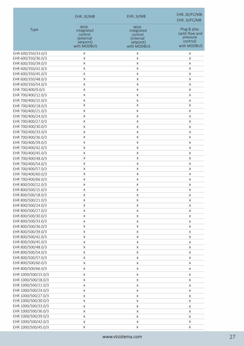
Type Plug & play (with flow and
pressure control)
with MODBUS
With integrated
setpoint)
control (external
with MODBUS
With integrated
setpoint)
control (internal
with MODBUS
Type
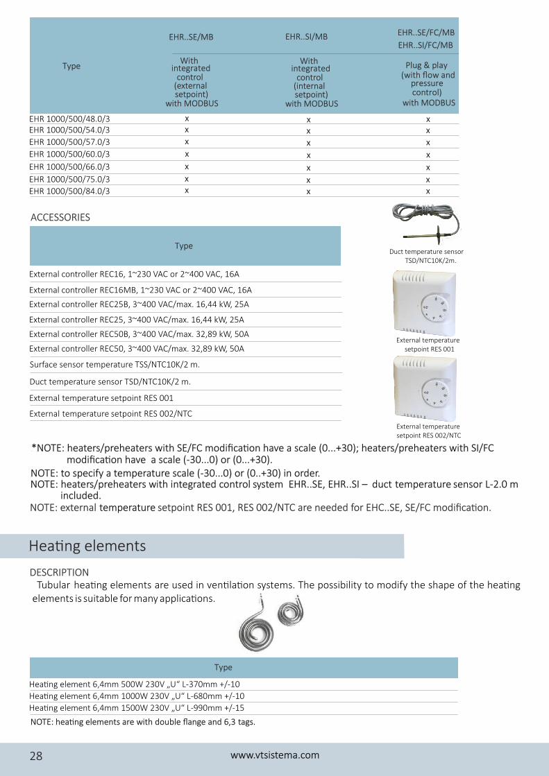
EHR 1000/500/48.0/3EHR 1000/500/54.0/3
EHR 1000/500/57.0/3
EHR 1000/500/60.0/3
EHR 1000/500/66.0/3
EHR 1000/500/75.0/3
EHR 1000/500/84.0/3
External controller REC16, 1~230 VAC or 2~400 VAC, 16A
Surface sensor temperature TSS/NTC10K/2 m.
Duct temperature sensor TSD/NTC10K/2 m.
External controller REC16MB, 1~230 VAC or 2~400 VAC, 16A
External controller REC25B, 3~400 VAC/max. 16,44 kW, 25A
External controller REC25, 3~400 VAC/max. 16,44 kW, 25A
External controller REC50B, 3~400 VAC/max. 32,89 kW, 50A
External controller REC50, 3~400 VAC/max. 32,89 kW, 50A
External temperature setpoint RES 001
External temperature setpoint RES 002/NTC
ACCESSORIES
Hea�ng elements
Tubular hea�ng elements are used in ven�la�on systems. The possibility to modify the shape of the hea�ng elements is suitable for many applica�ons.
NOTE: hea�ng elements are with double flange and 6,3 tags.
Type
Hea�ng element 6,4mm 500W 230V „U“ L-370mm +/-10
Hea�ng element 6,4mm 1000W 230V „U“ L-680mm +/-10
Hea�ng element 6,4mm 1500W 230V „U“ L-990mm +/-15
DESCRIPTION
www.vtsistema.com28
EHR..SI/MBEHR..SE/MB EHR..SE/FC/MB
EHR..SI/FC/MB
xx
x
x
x
xx
xx
x
x
x
xx
xx
x
x
x
xx
Duct temperature sensor TSD/NTC10K/2m.
External temperature setpoint RES 001
External temperature setpoint RES 002/NTC
*NOTE: heaters/preheaters with SE/FC modifica�on have a scale (0...+30); heaters/preheaters with SI/FC
NOTE: to specify a temperature scale (-30...0) or (0..+30) in order. modifica�on have a scale (-30...0) or (0...+30).
NOTE: heaters/preheaters with integrated control E .SE, EHR..SI – L-2.0 m system HR. duct temperature sensor included.
NOTE: external setpoint RES 001, RES 002/NTC are needed for EHC..SE, SE/FC modifica�on.temperature
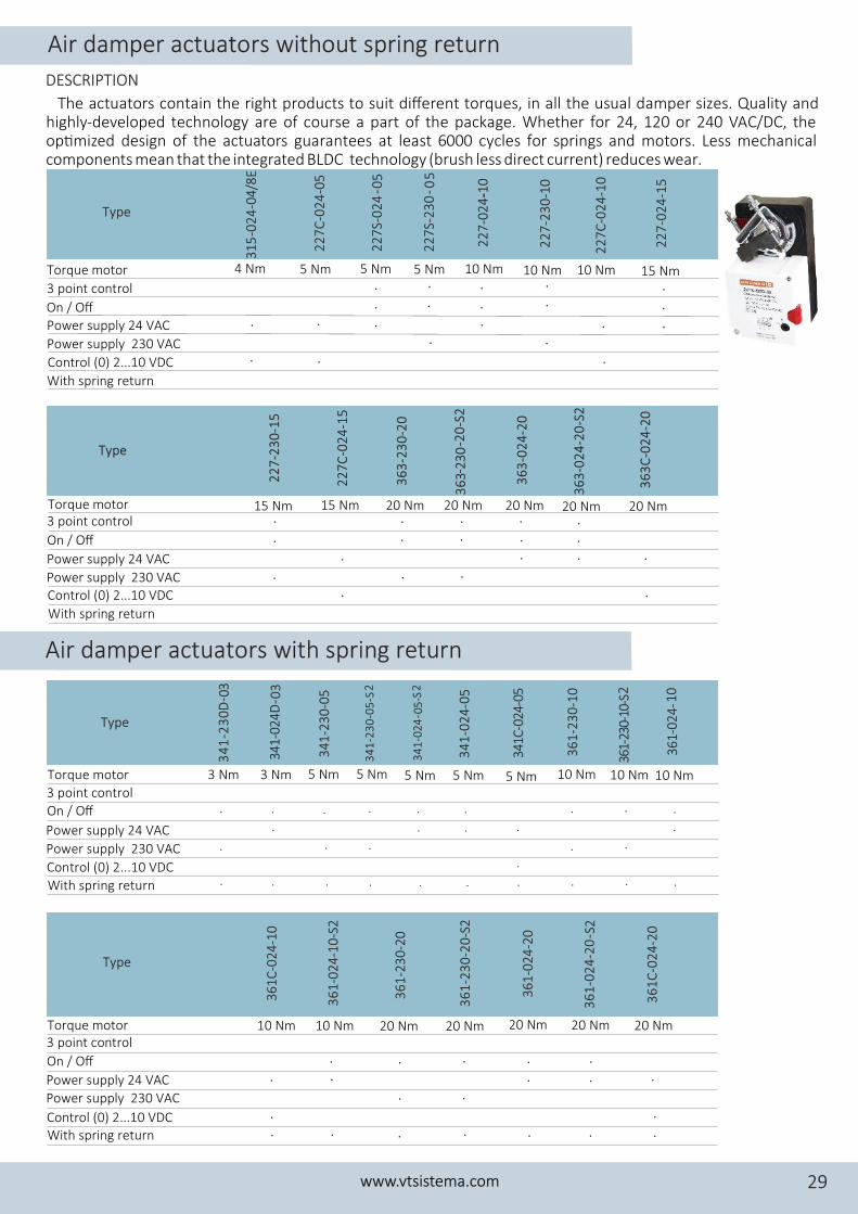
Air damper actuators with spring return
DESCRIPTION
Air damper actuators without spring return
15 Nm 15 Nm 20 Nm 20 Nm 20 Nm 20 Nm. .
. . .
.
. .
Torque motor3 point control
On / Off
Power supply 24 VAC
Power supply 230 VACControl (0) 2...10 VDC
With spring return
.
. ..
... .
Type
22
7-2
30
-15
22
7C
-02
4-1
5
36
3-2
30
-20
36
3-0
24
-20
36
3C
-02
4-2
0
36
3-2
30
-20
-S2
36
3-0
24
-20
-S2
.
.
.
20 Nm
Torque motor
3 point control
On / OffPower supply 24 VAC
Power supply 230 VAC
Control (0) 2...10 VDC
With spring return
5 Nm 5 Nm 5 Nm 10 Nm 10 Nm 15 Nm. . .
. . .. .
.. .
. .
.10 Nm4 Nm
.
.
.
Type
31
5-0
24
-04
/8E
22
7C
-02
4-0
5
2
27
S-0
24
- 05
22
7S-
23
0- 0
5
22
7-2
30
-10
22
7C
-02
4-1
0
22
7-0
24
-15
22
7-0
24
--10
.
.
..
The actuators contain the right products to suit different torques, in all the usual damper sizes. Quality and highly-developed technology are of course a part of the package. Whether for 24, 120 or 240 VAC/DC, the op�mized design of the actuators guarantees at least 6000 cycles for springs and motors. Less mechanical components mean that the integrated BLDC technology (brush less direct current) reduces wear.
www.vtsistema.com 29
23 3 2
Type
34
1-2
30
D- 0
341-
024
D- 0
34
1-2
30
-05
34
1-2
30
-05
-S
34
1-0
24
-05
341C
-024
-05
36
1-2
30
-10 2
361-
230-
10-S
3 Nm 3 Nm 5 Nm 5 Nm 5 Nm 5 Nm 10 Nm 10 Nm
. . . . . .
. . .
. . . . .
.
Torque motor
3 point control
On / Off
Power supply 24 VAC
Power supply 230 VAC
Control (0) 2...10 VDC
With spring return . . . . . . . .
34
1-0
24
- 05
-S
361
10
-024
-
5 Nm 10 Nm
.
.
.
.
.
Type
36
1-0
24
-10
-S2
36
1-2
30
-20
36
1-2
30
-20
-S2
36
1-0
24
-20
36
1-0
24
-20
- S2
36
1C
-02
4-2
0
10 Nm 20 Nm 20 Nm 20 Nm 20 Nm 20 Nm
. . . .
.. .
..
Torque motor 3 point control
On / Off
Power supply 24 VAC
Power supply 230 VAC
Control (0) 2...10 VDC With spring return . . . .
361
C-0
24
-10
10 Nm
.
.
. .
.
.
.
.
.
.
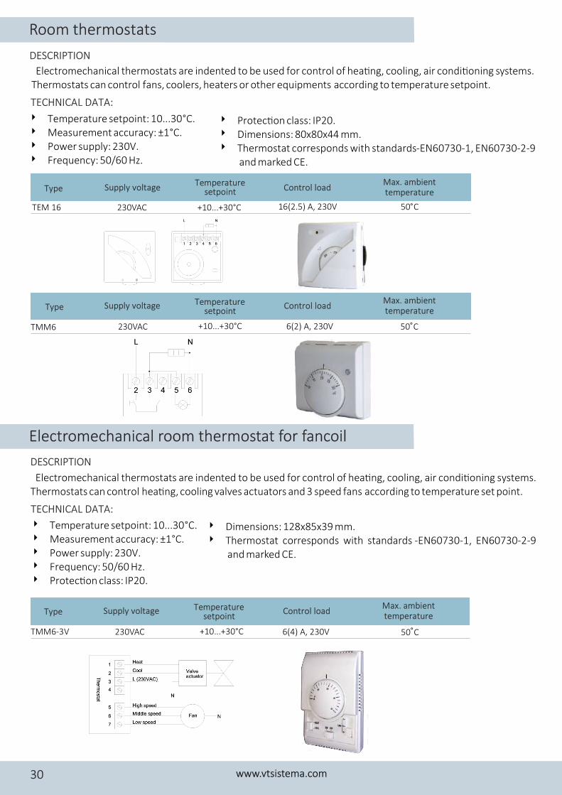
TMM6-3V 230VAC 6(4) A, 230V+10...+30°C 50°C
Electromechanical thermostats are indented to be used for control of hea�ng, cooling, air condi�oning systems. Thermostats can control fans, coolers, heaters or other equipments according to temperature setpoint.
Electromechanical thermostats are indented to be used for control of hea�ng, cooling, air condi�oning systems. Thermostats can control hea�ng, cooling valves actuators and 3 speed fans a ccording to temperature set point.
4 Temperature setpoint: 10...30 °C.4 Measurement accuracy: ±1°C.4 Power supply: 230V.4 Frequency: 50/60 Hz.
4 Temperature setpoint: 10...30 °C.4 Measurement accuracy: ±1°C.4 Power supply: 230V.4 Frequency: 50/60 Hz.4 Protec�on class: IP20.
4 Dimensions: 128x85x39 mm.4 Thermostat corresponds with standards -EN60730-1, EN60730-2-9
and marked CE.
Electromechanical room thermostat for fancoil
TEM 16
Type
230VAC
Supply voltage
16(2.5) A, 230V
Control load
+10...+30°C
Temperature setpoint
50
Max. ambient temperature
°C
TMM6 230VAC 6(2) A, 230V+10...+30°C 50°C
TECHNICAL DATA:
TECHNICAL DATA:
DESCRIPTION
DESCRIPTION
Room thermostats
www.vtsistema.com30
Type Supply voltage Control loadTemperature setpoint
Max. ambient temperature
Type Supply voltage Control loadTemperature setpoint
Max. ambient temperature
4 Protec�on class: IP20.4 Dimensions: 80x80x44 mm.4 Thermostat corresponds with standards- EN60730-1, EN60730-2-9
and marked CE.
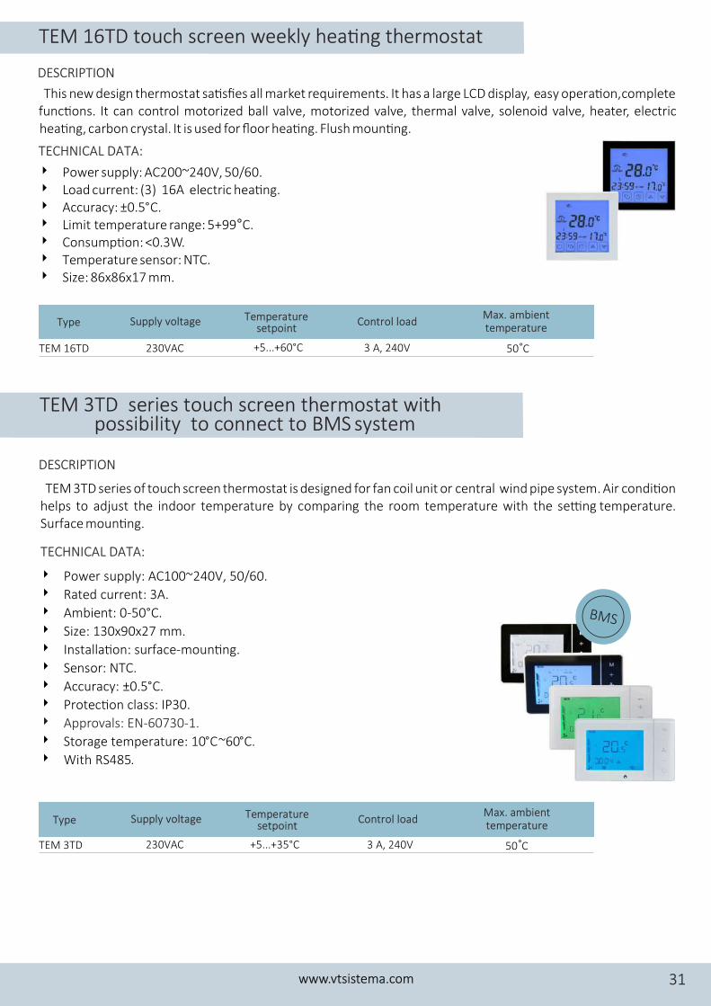
This new design thermos complete tat sa�sfies all market requirements. It has a large LCD display, easy opera�on, func�ons. It can ed ball valve, mot ized valve, ther , heater, electric control motoriz or mal valve, solenoid valvehea�ng, bon c ys tcar r tal. I is used for floor hea�ng. Flush moun�ng.
4 Power supply: AC200~240V, 50/60.4 Load current: (3) 16A electric hea�ng.4 Accuracy: ±0.5°C.4 Limit temperature range: 5+99°C.4 Consump�on: <0.3W.4 Temperature sensor: NTC.4 Size: 86x86x17 mm.
TEM 16TD 230VAC 3 A, 240V+5...+60°C 50°C
TECHNICAL DATA:
DESCRIPTION
TEM 3TD series touch screen thermostat with possibility to connect to BMS system
TEM 3TD series of touch screen thermostat designed for fan coil unit or central wind pipe system. Air c ondi�on ishelps to adjust the indoor temperature by comparing the room temperature with the se�ng temperature. Surface moun�ng.
4 Power supply: AC100~240V, 50/60.
4 Rated current: 3A.
4 Ambient: 0-50°C.
4 Size: 130x90x27 mm.
4 Installa�on: surface-moun�ng.
4 Sensor: NTC.
4 Accuracy: ±0.5°C.
4 Protec�on class: IP30.
4 Approvals: EN-60730-1.
4 Storage temperature: 10°C~60°C.
4 With RS485.
TEM 3TD 230VAC 3 A, 240V+5...+35°C 50°C
TECHNICAL DATA:
BMS
DESCRIPTION
TEM 16TD touch screen weekly hea�ng thermostat
www.vtsistema.com 31
Type Supply voltage Control loadTemperature setpoint
Max. ambient temperature
Type Supply voltage Control loadTemperature setpoint
Max. ambient temperature
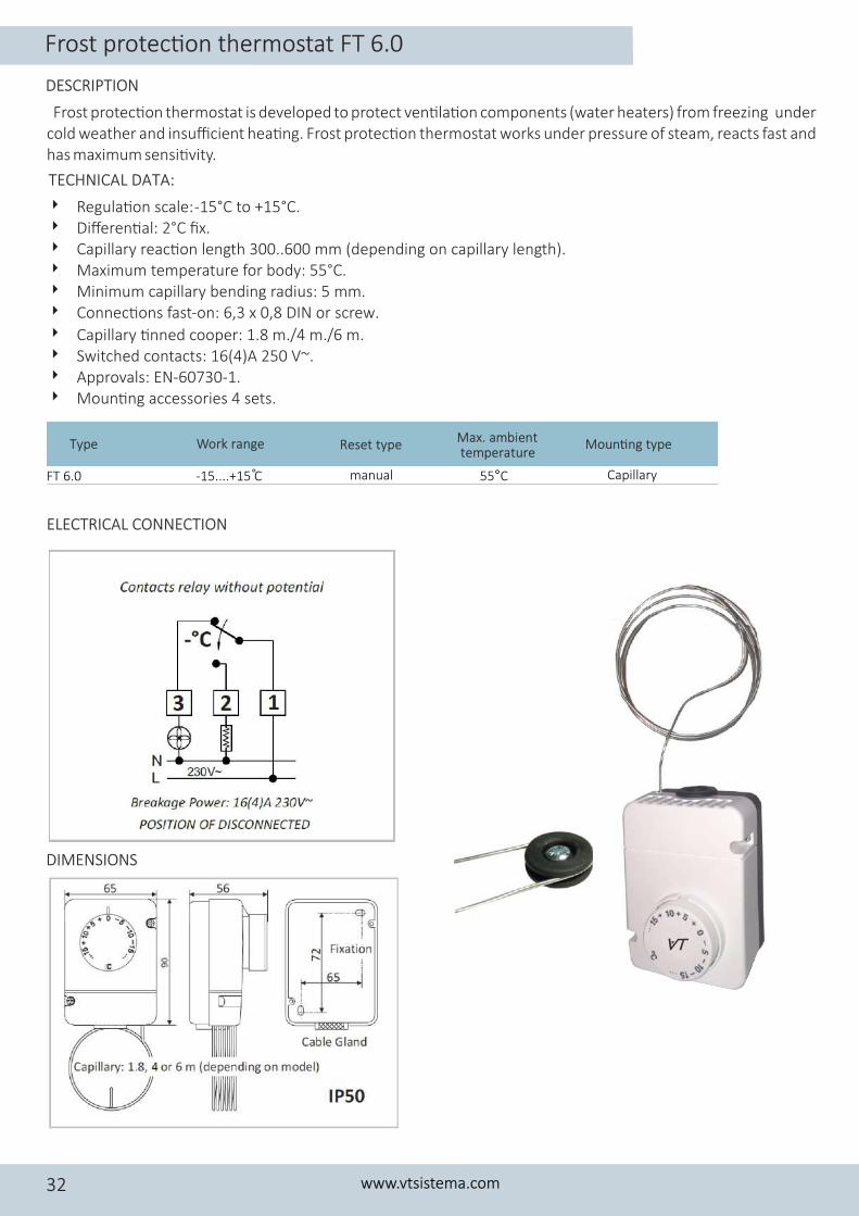
Frost protec�on thermostat is developed to protect ven�la�on components (water heaters) from freezing under cold weather and insufficient hea�ng. Frost protec�on thermostat works under pressure of steam, reacts fast and has maximum sensi�vity.
4 Regula�on scale: -15°C to +15°C.4 Differen�al: 2°C fix.4 Capillary reac�on length 300..600 mm (depending on capillary length).4 Maximum temperature for body: 55°C.4 Minimum capillary bending radius: 5 mm.4 Connec�ons fast-on: 6,3 x 0,8 DIN or screw.
4 Capillary �nned cooper: 1.8 m./4 m./6 m.4 Switched contacts: 16(4)A 250 V~.4 Approvals: EN-60730-1.4 Moun�ng accessories 4 sets.
Type Work range Reset type Moun�ng typeMax. ambient temperature
FT 6.0 -15....+15 C° manual 55°C Capillary
TECHNICAL DATA:
ELECTRICAL CONNECTION
DIMENSIONS
DESCRIPTION
Frost protec�on thermostat FT 6.0
www.vtsistema.com32
TY 95/AC, 70°C automa�c Capillary
TY 95/S, 100°C manual Capillary
TY 95/H, 100°C manual Capillary
T-24-60°C bimetallic automa�c Surface
T-24-70°C bimetallic automa�c Surface
T-24R-100°C manual Surface
70°C calibrated
100°C calibrated
100°C calibrated
60°C calibrated
70°C calibrated
100°C calibrated
150°C
150°C
150°C
100°C
100°C
150°C
Type Work range Reset type Moun�ng typeMax. Ambient temperature
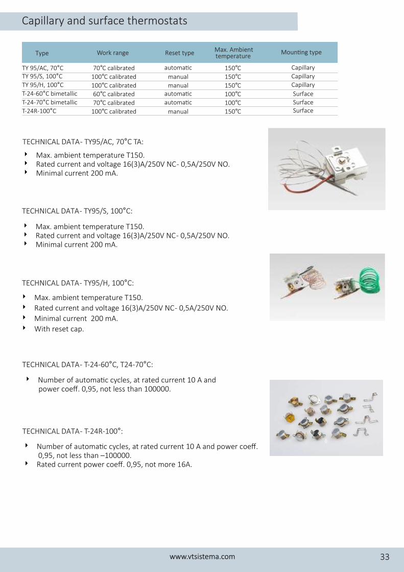
4 Max. ambient temperature T150. 4 Rated current and voltage 16(3)A/250V NC - 0,5A/250V NO.4 Minimal current 200 mA.
4 Max. ambient temperature T150. 4 Rated current and voltage 16(3)A/250V NC - 0,5A/250V NO.4 Minimal current 200 mA.
4 Max. ambient temperature T150.
4 Rated current and voltage 16(3)A/250V NC - 0,5A/250V NO.
4 Minimal current 200 mA.
4 With reset cap.
4 Number of automa�c cycles, at rated current 10 А and power coeff. 0,95, not less than 100000.
4 Number of automa�c cycles, at rated current 10 А and power coeff. 0,95, not less than –100000.
4 Rated current power coeff. 0,95, not more 16A.
TECHNICAL DATA - TY95/AC, 70°C TA:
TECHNICAL DATA - TY95/S, 100°C:
TECHNICAL DATA - TY95/H, 100°C:
TECHNICAL DATA - T-24-60°C, T24-70°C:
TECHNICAL DATA - T-24R-100°:
Capillary and surface thermostats
www.vtsistema.com 33
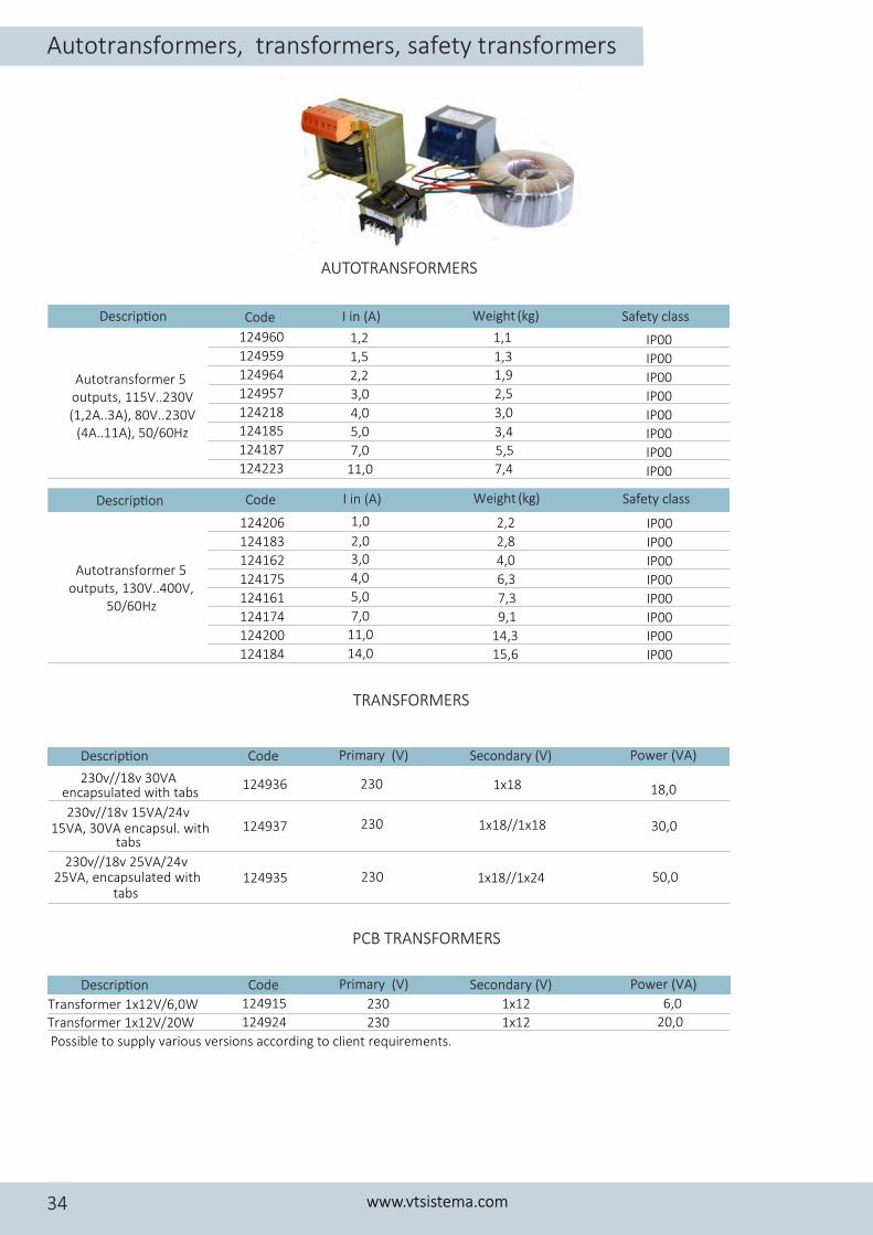
Autotransformer 5 outputs, 130V..400V,
50/60Hz
Descrip�on Code I in (A) Safety classWeight (kg)
124206 IP00124183 IP00124162 IP00124175 IP00124161 IP00124174 IP00124200 IP00124184
1,0 2,2
2,0 2,83,0 4,04,0 6,35,0 7,37,0 9,1
11,0 14,314,0 15,6 IP00
Descrip�on
124960 IP00124959 IP00124964 IP00124957 IP00124218 IP00124185 IP00124187 IP00124223
1,2 1,1
1,5 1,3
2,2 1,9
3,0 2,5
4,0 3,0
5,0 3,4
7,0 5,5
11,0 7,4 IP00
Autotransformer 5 outputs, 115V..230V (1,2A..3A), 80V..230V
(4A..11A), 50/60Hz
124936 230 1x18 18,0
124937 230 1x18//1x18 30,0
124935 230 1x18//1x24 50,0
230v//18v 30VA encapsulated with tabs
230v//18v 15VA/24v 15VA, 30VA encapsul. with
tabs
230v//18v 25VA/24v 25VA, encapsulated with
tabs
Descrip�on Code Primary (V) Secondary (V) Power (VA)
Transformer 1x12V/6,0W 124915 230 1x12 6,0
Transformer 1x12V/20W 124924 230 1x12 20,0
Possible to supply various versions according to client requirements.
AUTOTRANSFORMERS
TRANSFORMERS
PCB TRANSFORMERS
Autotransformers, transformers, safety transformers
www.vtsistema.com34
Code I in (A) Safety classWeight (kg)
Descrip�on Code Primary (V) Secondary (V) Power (VA)

.................................................................................
.................................................................................
.................................................................................
.................................................................................
.................................................................................
.................................................................................
.................................................................................
.................................................................................
.................................................................................
.................................................................................
.................................................................................
.................................................................................
.................................................................................
.................................................................................
.................................................................................
.................................................................................
.................................................................................
.................................................................................
.................................................................................
.................................................................................
.................................................................................
.................................................................................
.................................................................................
.................................................................................
.................................................................................
Note
www.vtsistema.com 35

CONTROL SYSTEMS TECHNOLOGIES
UAB “VTsistema“www.vtsistema.com
[email protected]@vtsistema.com
+37068720836+37067109182