Catalogue Cables & Accessories for Wind Turbines
214
Cables & Accessories for Wind Turbines 2013 / 2014 www.helukabel.com
-
Upload
hoanghuong -
Category
Documents
-
view
373 -
download
11
Transcript of Catalogue Cables & Accessories for Wind Turbines

Cables & Accessories for Wind Turbines
2013 / 2014
www.helukabel.com

HELUKABEL® is a global manufacturer and supplier of cables, wires & accessories.Founded in 1978, we are a recognized and trusted brand with an industry leading reputation for designing flexible, continuous flex and torsional cables.
Based on our strong and dedicated R&D team and continuous investments in our factory’s machinery, we are able to offer high-performance products featuring advanced technologies and – whenever an option – customized engineering for a variety of applications such as automation & material handling, in particular robotic applications, renewable energy and infrastructure facilities.
The HELUKABEL® Distribution Centre in Germany, housing more than 33.000 products andhaving more than 40.000 pallet storage space available, warehouse locations in more than50 countries and over 650 employees around the world make sure that your shipment arrivesright on time and wherever needed.
In this catalog we compiled our products for wind energy applications. HELUKABEL® offers thebenefit of over 15 years of expertise in manufacturing wind power cables. Our HELUWIND®
WK-Series comprises a perfectly coordinated line of cables, wires and accessories to equip theentire turbine.
For more information, please contact our Product Manager at the German Headquarters(+49 7150 9209 135) or your local representative.
Welcome to HELUKABEL®
The logistic centre Hemmingen
Cables & Wires
Custom Cables
Media Technology
Data, Network & Bus Technology
Cable Accessories
Branch
Exclusivagent

3
List of contents Functional view of Wind Power Station 5Selection table Cables & Wires 6-9Our Berlin Warehouse 10Research & Development 11Torsion Cables HELUWIND® WK 103w-Torsion 12-13HELUWIND® WK 103w EMV D-Torsion 14-15HELUWIND® WK 103k-Torsion 16-17HELUWIND® WK 103k EMV D-Torsion 18-19HELUWIND® WK 135-Torsion 20-21HELUWIND® WK 135 EMV D-Torsion 22-23HELUWIND® WK 137-Torsion FT4 24-25HELUWIND® WK 137 EMV D-Torsion FT4 26-27HELUWIND® WK Brandmeldekabel-Torsion 28HELUWIND® WK 101 H 29HELUWIND® WK H07BN4-F WIND-Torsion 30HELUWIND® WK THERMFLEX 145 31HELUWIND® WK 300w-Torsion 1,8/3kV 32HELUWIND® WK 303w-Torsion 1,8/3kV, UL 2kV 33HELUWIND® WK 305-Torsion 1,8/3kV 34HELUWIND® WK 335-Torsion 2,0/3,3kV, UL 2kV 35HELUWIND® WK MS-Single-Torsion 36HELUWIND® WK MS-Single-Torsion UL/CSA 37HELUWIND® WK MS-Multi-Torsion 38HELUWIND® WK MS-Multi-Torsion UL/CSA 39HELUWIND® WK DLO 2kV 40HELUWIND® WK RHH/RHW-2 ALU 41Flexible ALU/Cu Cables HELUWIND® WK POWERLINE ALU 105°C, 0,6/1kV 43HELUWIND® WK POWERLINE ALU robust 105°C, 0,6/1kV 44HELUWIND® WK POWERLINE ALU 105°C, 1,8/3kV 45HELUWIND® WK POWERLINE ALU robust 105°C, 1,8/3kV 46HELUWIND® WK POWERLINE ALU halogen free, 105°C 1,8/3kV 47HELUWIND® WK POWERLINE Copper Tower 48HELUWIND® WK POWERLINE ALU Tower 49HELUWIND® WK POWERLINE Blade Copper 50HELUWIND® WK POWERLINE Blade ALU 51Tower & Infrastructure CablesNYY-J und NYY-O 52-53NAYY 54NA2XY 55N2XH 56HELUWIND® WK (N)A2XH 57N2XS2Y 6/10kV, 12/20kV, 18/30kV 58NA2XS2Y 6/10kV, 12/20kV, 18/30kV 59N2XS(F)2Y 6/10kV, 12/20kV, 18/30kV 60NA2XS(F)2Y 6/10kV, 12/20kV, 18/30kV 61Control Cables JZ-500 62-63JZ-500 COLD 64F-CY-JZ 65-66Y-CY-JZ 67-68JZ-500 HMH 69-70JZ-500 HMH-C 71-72MEGAFLEX® 500 73-74MEGAFLEX® 500-C 75-76JZ-600 77-78JZ-600-Y-CY 79-80Single 600-J/-O 81Single 600-CY -J/-O 82JZ-600 HMH 83-84JZ-600 HMH-C 85-86JZ-600 UL/CSA 87-88JZ-600-Y-CY UL/CSA 89-90
JZ-602 91-92JZ-602-CY 93-94JZ-603 95JZ-603-CY 96H07 RN-F 97-98H07RN-F/SOOW 99HELUTHERM® 145 MULTI 100-101HELUTHERM® 145 MULTI-C 102-103Single Conductors H07 V-K / (H)07 V-K 104H05Z-K / H07Z-K 105FIVENORM 106HELUTHERM® 145 107-108THHN/THWN 109Data Cables PAAR-TRONIC-CY 110-111DATAFLAMM 112DATAFLAMM-C 113DATAFLAMM-C-PAAR 114Command Cable UL (LiYY) 115Command Cable UL (LiYCY) 116-117Command Cable UL (LiYY-TP) 118-119Command Cable UL (LiYCY-TP) 120-121SUPERTRONIC®-PURö 122SUPERTRONIC®-C-PURö 123SUPERTRONIC-330 PURö 124SUPERTRONIC-330 C-PURö 125SUPER-PAAR-TRONIC-C-PUR 126SUPER-PAAR-TRONIC 340-C-PUR 127NFPA 79 Edition 2012 – Challenges and solutions 128NFPA 79 Edition 2012 – Challenges and solutions 129TC TRAY CABLES UL/CSA TRAYCONTROL 300 130-131TRAYCONTROL 300-C 132-133TRAYCONTROL 300 TP 134-135TRAYCONTROL 300-C TP 136-137TRAYCONTROL 500 138-139TRAYCONTROL 500-C 140-141JZ 604 TC TRAY CABLE 142-143JZ 604-YCY TC TRAY CABLE 144TRAYCONTROL 600 145-146TRAYCONTROL 600-C 147TRAYCONTROL 610 OIL RES II, WTTC (2277), FT4T 148-149Industrial Cables and Wires MULTIFLEX 600 150MULTIFLEX 600-C 151TOPFLEX® 600 VFD 152TOPFLEX® 650 VFD 153Communication Cables for Wind Turbines Communication technology for wind turbines 155Fiber Optic Communication 156Connection equipment 158-159Fibre Optic connecting technic 160-161Connection equipment 162-163Machine outlet IP67 164Machine outlet IP65 165Industrial Ethernet 166-167BUS Cables 168-171Fiber Optic Cable flexible 172-174Fiber Optic Breakout Cable robust 175-176Plastic-fibre cable industry 177Fibre Optic Indoor/Outdoor Cable 178Fibre Optic Outdoor Cable 179-181Fibre Optic Outdoor Cable 182

4
List of contents Cable Accessories Cable accessories for wind power plants 183Cable conduit and cable grips 184Cable gland – HELUTOP® 185WK-CU compression cable lug 188WK-AL compression cable lug 189WK-AL compression cable lug FG extruded 188WK-AL/CU compression cable lugs 189WK-AL compression connector 190WK-AL/CU compression connector 191Bolt connector 192HYDAC - Fastening systems in the turret 193Cable clamps 194HELUWIND® WK-Multiclamp 195The Roxtec Sealing Solution 196-197Cable fittings 198-199Shrink-on tube SK-D 200Additional accessories 201Tools 202CCC-Certification for China 203Achieving success through quality and innovation 204Technical Data Current ratings for HELUWIND® 205-207Current ratings – Conversion factors 208-209Current ratings for HELUWIND® 210Current carrying capacity for Wk Powerline ALU 211Current carrying capacity 212-213Current ratings for UL-CSA cables 214Glossary of Therms 215-217Part No. index 218-221How to get in touch with our Wind Power Specialists 222

5
Functional view of Wind Power Station
Cables and wiresfor use in:
Pod Cable loop Tower Tower control / transformer Base of tower
Rotor bladeGearbox
Brake
Pod
Rotor hub & blade adjustment
Wind-direction tracking
Generator
Tower
Base
Medium-high voltage level
Tower control / transformer

6
Torsion Cables Usa
ge,
see
ch
art
on
pag
e 5
UL-
Styl
e
CSA
CE
VD
E*
fire
tes
ts F
T4/6
0332
-3
fire
tes
ts F
T1 (w
ith
FT2
)/60
332-
1
no
min
al v
olt
age
acco
rdin
g t
o U
L
no
min
al v
olt
age
acco
rdin
g t
o V
DE
hal
og
en-f
ree
oil
resi
stan
t II*
*
oil
resi
stan
t
UV-
resi
stan
t
off
sho
re e
mp
loym
ent
tem
p. n
on
-flex
ing
fro
m (i
n °
C)
tem
p. n
on
-flex
ing
to
(in
°C
)
tem
p. fl
exin
g f
rom
(in
°C
)
tem
p. fl
exin
g t
o (i
n °
C)
twis
tab
le +
/- 1
50°
per
met
er
twis
tab
le +
/- 1
40°
per
met
er
twis
tab
le +
/- 1
00°
per
met
er
can
be
fou
nd
on
pag
e
WK 103w-T1067821179
cRUus X X 1000V0,6/1kV
X (*) X X -40 +90 -35 +90 X 12
WK 103w EMV D-T1067821179
cRUus X X 1000V0,6/1kV
X (*) X X -40 +90 -35 +90 X 14
WK 103k-T102692570
cRUus X X 1000V0,6/1kV
X X -40 +80 -40 +80 X 16
WK 103k EMV D-T102692570
cRUus X X 1000V0,6/1kV
X X -40 +80 -40 +80 X 18
WK 135-T1055320234
cRUus X X60332
-31000V
0,6/1kV
X X X X X -40 +90 -40 +90 X 20
WK 135 EMV D-T1055320234
cRUus X X60332
-31000V
0,6/1kV
X X X X X -40 +90 -40 +90 X 22
WK 137-T FT41055320234
cRUus X X X 1000V0,6/1kV
X X X X X -40 +90 -40 +90 X 24
WK 137 EMV D-T FT41055320234
cRUus X X X 1000V0,6/1kV
X X X X X -40 +90 -40 +90 X 26
WK Fire Alarm Cable-T X X300/ 500V
X X X -50 +90 -40 +80+/-
216°28
WK 101 H X0,6/1kV
X X X -50 +100 -40 +90 29
WK H07BN4-F WIND-T X450/750V
X -45 +90 -35 +90 X 30
WK Thermflex 145 X60332
-30,6/1kV
X X X -55 +145 -20 +120 31
WK 300w-T 60332
-11,8/3kV
X X -40 +90 -35 +90 X 32
WK 303w-T 1,8/3kV, UL 2kV
X X X 2000V1,8/3kV
X X -40 +90 -35 +90 X 33
WK 305-T X60332
-31,8/3kV
X X X X X -40 +90 -40 +90 X 34
WK 335-T 2,0/3,3kV, UL 2kV
X X X 2000V1,8/
3,3kVX X X X X -40 +90 -40 +90 X 35
WK MS-Single-T3,6- 20kV
X X -40 +90 -40 +90 X 36
WK MS-Single-T UL/CSA X X3,6-20kV
X X -40 +90 -40 +90 X 37
WK MS-Multi-T3,6-38kV
X X -40 +90 -40 +90 X 38
WK MS-Multi-T UL/CSA X X3,6-38kV
X X -40 +90 -40 +90 X 39
WK DLO 2kV UL 44 X X X 2000V X -40 +90 40
WK RHH/RHW-2 ALU X 2000V X -40 +90 41
WK Powerline ALU 105°C, 0,6/1kV
X60332
-10,6/1kV
X X -40 +105 -20 +90 43
WK Powerline ALU robust 105°C, 0,6/1kV
X60332
-10,6/1kV
X X -40 +105 -20 +90 44
WK Powerline ALU 105°C, 1,8/3kV
60332-1
1,8/ 3kV
X X -40 +105 -20 +90 45
WK Powerline ALU robust 105°C, 1,8/3kV
60332 -1
1,8/ 3kV
X X -40 +105 -20 +90 46
WK Powerline ALU halogen-free 105°C, 1,8/3kV
1,8/ 3kV
X X -40 +105 -20 +90 47
WK Powerline Copper Tower
X0,6/ 1kV
X X -40 +90 -25 +50 48
WK Powerline ALU Tower
X0,6/ 1kV
X X -40 +90 -25 +50 49
WK Powerline Blade Copper
X0,6/1kV
X -40 +80 50
WK Powerline Blade Alu
X0,6/1kV
X -40 +80 51
* in preparation ** in accordance with UL 1277, Table 11.2
Selection table Cables & Wires

7
Selection table Cables & Wires
Control Cables Usa
ge,
see
ch
art
on
pag
e 5
UL-
Styl
e
CSA
CE
HA
R
wit
h V
DE
Reg
.-N
o.
FT1
equ
ival
ent
to IE
C 6
0332
-1
no
min
al v
olt
age
acco
rdin
g t
o U
L
no
min
al v
olt
age
acco
rdin
g t
o V
DE
hal
og
en-f
ree
larg
ely
oil
resi
stan
t
UV-
resi
stan
t
tem
p. n
on
-flex
ing
fro
m (i
n °
C)
tem
p. n
on
-flex
ing
to
(in
°C
)
tem
p. fl
exin
g f
rom
(in
°C
)
tem
p. fl
exin
g t
o (i
n °
C)
Cu
-Sh
ield
can
be
fou
nd
on
pag
e
JZ-500 X X X300/500V
X -40 +80 -15 +80 62
JZ-500 COLD X X300/500V
X X -40 +80 -30 +80 64
F-CY-JZ X X X300/500V
X -40 +80 -40 +80 65
Y-CY-JZ X X X300/500V
-40 +80 -5 +80 X 67
JZ-500 HMHJZ-500 HMH-C
X 60332-3300/500V
X X -40 +70 -15 +70 X69 71
MEGAFLEX 500MEGAFLEX 500-C
X X X 60332-3300/600V
300/500V
X X X -40 +80 -30 +90 X7375
JZ-600JZ-600-Y-CY
X X0,6/1kV
X X -40 +80 -5 +80 X7779
Single 600-J/-OSingle 600-CY -J/-O
X X X X 600 V0,6/1kV
X -40 +90 -5 +90 X8182
JZ-600 HMHJZ-600 HMH-C
X 60332-30,6/1kV
X X X -40 +70-15-5
+70 X8385
JZ-600-UL/CSAJZ-600-Y-CY-UL/CSA
X X X X 1kV0,6/1kV
Xinsw
-40 +80 -5 +80 X8789
JZ-602JZ-602-CY
X X X X 600V X -40 +90 -5 +90 X9193
JZ-603JZ-603-CY
X X X X X 600V300/500V
X -40 +70 -5 +70 X9596
H07RN-FH07RN-F/SOOW
X X X X 600V450/750V
X -40 +909799
HELUTHERM 145 MULTIHELUTHERM 145 MULTI-C
X 60332-3300/500V
to 1,0 mm2
450/750Vfrom 1,5 mm2
X X X -55 +145 -35 +120 X100102
LiYY-TP-UL X X X 300V X -20 +80 -10 +80 X115116
JZ-604 TC TRAY CABLE X X X FT4 600V X -25 +90 -5 +90 142
Data Cables
PAAR-TRONIC-CY X X350/500V
X -30 +80 -5 +80 X 110
DATAFLAMM DATAFLAMM-C
X X350/500V
X-40
+70 -5 +70 X112113
DATAFLAMM-C-PAAR X X350/500V
X-40
+70 -5 +70 X 114
UL (LiYY) X X X 300V X -20 +80 -10 +80 X 115
UL (LiYCY) X X X X 300V X -20 +80 -10 +80 X 116
UL (LiYY-TP) X X X X 300V X -20 +80 -10 +80 118
UL (LiYCY-TP) X X X X 300V X -20 +80 -10 +80 X 120
SUPERTRONIC®-PURö SUPERTRONIC®-C-PURö
X 350V X-40
+70 -5 +70 X122123
SUPERTRONIC®-330 PURö SUPERTRONIC®-330-C-PURö
X X X X 300V 300V X X-50
+80 -40 +80 X124125
SUPER-PAAR-TRONIC-C-PUR® SUPER-PAAR-TRONIC 340-C-PUR® X X X X 300V 350V X X
-50+70 -40 +70 X
126127

8
Selection table Cables & Wires
Single Conductors Usa
ge,
see
ch
art
on
pag
e 5
UL-
Styl
e
CSA
CE
HA
R
wit
h V
DE
Reg
.-N
o.
FT1
equ
ival
ent
to IE
C 6
0332
-1
no
min
al v
olt
age
acco
rdin
g t
o U
L
no
min
al v
olt
age
acco
rdin
g t
o V
DE
hal
og
en-f
ree
larg
ely
oil
resi
stan
t
UV-
resi
stan
t
tem
p. n
on
-flex
ing
fro
m (i
n °
C)
tem
p. n
on
-flex
ing
to
(in
°C
)
tem
p. fl
exin
g f
rom
(in
°C
)
tem
p. fl
exin
g t
o (i
n °
C)
Cu
-Sh
ield
can
be
fou
nd
on
pag
e
H07 V-K/(H)07 V-K H05Z-K/H07Z-K
X X X-30-40
+80+90
-5 +70104105
FIVENORM X X X X X-40-55
+90+145
-5-35
+90+120
106
HELUTHERM 145 600V HELUTHERM 145 600V UL
X X X X X -55 +125 -35 +120107108
THHN/THWN X X 600V X X 109
TC TRAY CABLES USA
TRAYCONTROL 300 X X X FT4 300V X -25 +105 -25 +105 130
TRAYCONTROL 300-C X X X FT4 300V X -25 +105 -25 +105 X 132
TRAYCONTROL 300 TP X X X FT4 300V X -25 +105 -25 +105 134
TRAYCONTROL 300-C TP
X X X FT4 300V X -25 +105 -25 +105 X 136
TRAYCONTROL 500 1277 X X FT4 1000V X -40 +90 -5 +90 138
TRAYCONTROL 500-C 1277 X X FT4 1000V X -40 +90 -5 +90 X 140
JZ-604 TC TRAY CABLE 1277 X X FT4 600V X X -25 +90 -5 +90 142
JZ-604-YCY TC TRAY CABLE
1277 X FT4 600V X X -25 +90 -5 +90 X 144
TRAYCONTROL 600 1277 X X FT4 1000V X X -40 +90 -5 +90 145
TRAYCONTROL 600-C 1277 X X FT4 1000V X X -40 +90 -5 +90 X 147
TRAYCONTROL 610 OIL RES II
2277 X FT4 1000V X X -40 +90 -5 +90 148
MULTIFLEX 600 X X X X 600V X X X -40 +90 -5 +90 150
MULTIFLEX 600-C X X X X 600V X X X -40 +90 -5 +90 X 151
TOPFLEX 600 VFD X X X 600V X X -25 +90 X 152
TOPFLEX 650 VFD X X X 600V X X -25 +90 X 153
Communication Cables
Industrial Ethernet 105°C Torsion
X X X 60332-1 300V 100V X X X -40 +105 -40 +105 X 166
Industrial Ethernet S-FTP TORDIERFLEX
X X X 60332-1 300V 100V X X X -20 +80 -20 +80 X 167
BUS Cable HELUWINDWK CAN BUS 105°C
X X X X 600V 100V X X X -40 +105 -20 +60 X 168
BUS Cable indoor Profibus SK outdoor
X_
X_
XX
X_
600V_
100V100V
–X
––
XX
-40-40
+70+70
-5-5
+60+60
XX
169
BUS Cable Torsion Profibus L2 Festoon
X_
CMX_
XX
XX
300V_
100V100V
XX
XX
XX
-40-40
+75+70
-25-5
+75+60
XX
170
BUS Cable FRNC Profibus SK industry
X X
_ X
FT4 FT1
300V 300V
100V 100V
X X
X X
X X
-25-40
+70+70
-25 -40
+70+70
XX
171
AT-V(ZN)Y(ZN)Y AT-V(ZN)H(ZN)11Y
submitted_
submitted_
FT4submitted
_ XXX
XX
-40-40
+90+90
-40-40
+90+90
172
LWL-Cable mobile, trailing A-V(ZN)11Y
60332-1 X X X -30 +70 -20 +70 173
LWL-Cable mobile A-V(ZN)Y
X X FT4 X X -30 +80 -20 +80 174

9
Selection table Cables & Wires
Communication Cables U
sag
e, s
ee c
har
t o
n p
age
5
UL-
Styl
e
CSA
CE
HA
R
wit
h V
DE
Reg
.-N
o.
FT1
equ
ival
ent
to IE
C 6
0332
-1
no
min
al v
olt
age
acco
rdin
g t
o U
L
no
min
al v
olt
age
acco
rdin
g t
o V
DE
hal
og
en-f
ree
larg
ely
oil
resi
stan
t
UV-
resi
stan
t
tem
p. n
on
-flex
ing
fro
m (i
n °
C)
tem
p. n
on
-flex
ing
to
(in
°C
)
tem
p. fl
exin
g f
rom
(in
°C
)
tem
p. fl
exin
g t
o (i
n °
C)
Cu
-Sh
ield
can
be
fou
nd
on
pag
e
Fibre Optic Breakout Cable industry HCS I-V(ZN)YY
X X FT4 X X -30 +85 -20 +85 175
Fibre Optic Breakout Cableindustry HCS I-V(ZN)Y11Y
X X -20 +80 -20 +80 176
Plastic-fibre Optic cable industry POF/PE I-V2Y, I-V2Y(ZN)11Y
60332-1 X X -20 +80 -20 +80 177
Fibre Optic Universal Cable A/I-DQ(ZN)BH
60332-1 X X X -20 +60 -5 +50 178
Fibre Optic Outdoor Cable A-DQ(ZN)B2Y (central)
X X -20 +60 -5 +50 179
Fibre Optic Outdoor Cable A-DQ(ZN)B2Y (central)
– – X X -20 +60 -5 +50 180
Fibre Optic Outdoor Cable A-DQ(ZN)B2Y (stranded)
X X -20 +60 -5 +50 181
Fibre Optic Outdoor Cable A-DQ(ZN)B2Y (stranded, Multifibre)
X X -20 +60 -5 +50 182
Tower & Infrastructure Cables
NYY-J/-0 X X0,6/1kV
-40 +70 -5 +50 52
NAYY X X0,6/1kV
-40 +70 -5 +50 54
NA2XY X X0,6/1kV
-40 +70 -5 +50 55
N2XH X X0,6/1kV
X -30 +90 -5 +50 56
WK (N)A2XH X 60332-30,6/1kV
X X -40 +90 -5 +50 57
N2XS2Y 6-30kV X -40 +90 X 58
NA2XS2Y 6-30kV X -40 +90 X 59
N2XS(F)2Y 6-30kV X -40 +90 X 60
NA2XS(F)2Y 6-30kV X -40 +90 X 61

10
Our Berlin Warehouse
Direct burial and medium voltage cables available for immediate delivery from stock
Our Handling - Your individual requirements are important
- Unless otherwise requested, the cable is cut to length and coiled on drums automatically
- Cutting is performed with 10 tons cut to length machines
- 50.000 m2 storage area in Berlin
- Various types and cross-sections available
- VDE-certified, DIN VDE 0276
- On-time delivery on the construction site; on disposable drums if required
- Deliveries at short notice, including cuts to length and follow-up deliveries

11
Research & Development
Up to 20 cables with outer diameters from 5 mm up to 100 mm can be mounted and tested simultaneously in the girder mast where these cables are exposed to sun, rain, wind, snow and UV-radiation at the same time.
A special drive and control software allows HELUKABEL’s engineers to repeatedly run 1200°-torsion cycles in each direction.
The HELUWIND® WK-torsion series have been tested successfully for more than 16.000 torsion cycles. This operational reliability is signi-ficantly longer than the standard lifetime of a wind turbine (5000 – 10000 cycles).
Torsion test centre at German production site
For several years HELUKABEL® has been testing its torsional wind turbine cables in an 8m/26ft-high re-search tower at the German production site. The acquired findings had a significant effect on the development of the latest generation of HELUWIND® WK-cables.
HELUKABEL® is the only manufacturer that replicated the cable loop of a wind turbine 1:1 and is able to perform tests under realistic conditions.

12
HELUWIND® WK 103w-TorsionUV-resistant, UL/CSA-Style 10678/21179 Single-/Multiconductor
PropertiesCable structureTechnical dataSpecial bare copper conductors, finestranded according to EC
Temperature rangeflexing -35°C to +9 °Cfixed installation -4 °C to +9 °Cinstallation - °C to +9 °C
UV-resistantmulti-climate operation
Special heat-resistant insulation torsion testedCore identification JZ: black with whitenumbers + Gn/Yl ground
flame-retardantOperating temperature at conductormax. +9 °C
oil-resistantMulticonductors cabled recyclable
Nominal voltageacc. to VDE U /U , / kVacc. to UL V
Jacket special heat-resistant compound easy to assembleBlack jacket
NoteTest voltage 50 Hz:4 V
Other diameters, part-no. and prices onrequest.Please contact us with your individualrequirements viafax +49 5 9 9 5 35.Highest permissible Voltage
DC: Conductor/Conductor , kV Conductor/Earth ,9kVAC: Conductor/Earth , kVThree phase: Conductor/Conductor , kV
Minimum bending radius x cable diameter
(4 x for fixed installation)Torsion application+/- 4 ° per mApprovalsUL-Style Singleconductor 4 mmUL-Style 9 MulticonductorcRUusFlame test
T , VW- , EC 33 -
ApplicationThe WK 3w was designed for flexible use, especially to accommodate the torsional stress in the cable loop of a wind turbine. The cable isdesigned for a voltage level for . / kV for all dimensions, whereby individual cables can also be routed in parallel for standard conformityaccording to UL. A spatial separation of the cable routes is no longer necessary. The WK series was successfully tested with over ,torsion cycles and thus offers optimal functional safety well beyond the service life of the wind turbine.
= The product conforms to the EC Low Voltage Directive /95/EC
Continuation
13
HELUWIND® WK 103w-TorsionUV-resistant, UL/CSA-Style 10678/21179 Single-/Multiconductor
Core identification JZCore identification JZWeightapprox.g / m
Cop.weightg / m
Outer Øapprox.mm
AWG-No.No.cores xcross-sec.mm
Part no. Weightapprox.g / m
Cop.weightg / m
Outer Øapprox.mm
AWG-No.No.cores xcross-sec.mm
Part no.
86,029,07,1224 G 0,34704809 1030,0576,025,01640 G 1,57048551050,0591,025,01641 G 1,570485699,033,47,4204 G 0,57048101200,0720,027,71650 G 1,5704857121,051,28,6206 G 0,5704811
150,872,08,9143 G 2,5704267165,048,010,82010 G 0,5704812208,084,011,12012 G 0,5704813 230,096,09,7144 G 2,5703925
237,9120,010,9145 G 2,570392667,822,06,5193 G 0,75704814360,0168,014,4147 G 2,5704858100,029,07,9194 G 0,75704815480,0240,015,81410 G 2,5704859120,036,08,6195 G 0,75704816527,0288,016,31412 G 2,5704367137,451,010,0197 G 0,75704817590,0456,021,01419 G 2,5705040200,072,011,01910 G 0,75704818227,5116,010,8123 G 4704368220,087,011,81912 G 0,75704819
238,0101,012,51914 G 0,75704820 286,8154,012,0124 G 4703930365,7192,013,6125 G 4704269271,0116,013,21916 G 0,75704821
310,0130,013,91918 G 0,75704822 489,0269,015,9127 G 4704860740,0461,019,61212 G 4704861380,0152,015,21921 G 0,75704823
490,0180,016,91925 G 0,75704824 340,0173,013,1103 G 6704862560,0231,018,21932 G 0,75704825 460,0231,014,6104 G 6704863620,0260,019,11936 G 0,75704826 566,4288,016,3105 G 6704864729,0288,020,51940 G 0,75704827 780,0404,019,6107 G 6704865750,0296,020,81941 G 0,75704828 540,0228,016,483 G 10706318990,0441,023,51950 G 0,75704829 670,0384,017,484 G 10704866100,039,08,3184 G 1704830 851,2480,020,185 G 10703932110,048,09,0185 G 1704831 1150,0672,023,587 G 10704867140,068,010,5187 G 1704832 1180,7615,020,764 G 16704868220,096,013,01810 G 1704833 1348,1768,025,465 G 16703933240,0116,013,21812 G 1704834 1576,2960,026,444 G 25704869280,0135,013,41814 G 1704835 1900,01200,028,245 G 25704870310,0154,014,11816 G 1704836 286,81344,031,424 G 35704871360,0173,015,11818 G 1704837 2770,61680,035,425 G 35704872410,0202,016,71821 G 1704838 2800,01920,036,714 G 50704873500,0240,018,41825 G 1704839590,0308,019,81832 G 1704840700,0346,020,61836 G 1704841 Weight
approx.g / m
Cop.weightg / m
Outer Øapprox.mm
AWG-No.No.cores xcross-sec.mm
Part no.800,0384,022,41840 G 1704842810,0394,022,41841 G 1704843980,0480,024,61850 G 1704844 454,4336,012,921 x 3570428775,029,07,9162 G 1,5704845 630,2480,015,611 x 50704288
104,944,08,0163 G 1,5703920 876,8672,017,92/01 x 70704289132,058,08,9164 G 1,5703921 1230,0912,021,93/01 x 95704874157,172,09,7165 G 1,5703922 1535,11152,023,14/01 x 120704291230,8101,012,0167 G 1,5704366
2966,81440,027,2300 kcmil1 x 150704875270,0144,013,11610 G 1,5704846
2284,01776,027,5350 kcmil1 x 185704293360,0173,014,31612 G 1,57048472966,82304,031,2500 kcmil1 x 240704294420,0202,014,91614 G 1,57048483672,02880,034,2600 kcmil1 x 300704295450,0231,015,71616 G 1,57048494500,03840,039,3750 kcmil1 x 400704876510,0260,016,81618 G 1,5704850
590,0303,017,81621 G 1,5704851700,0360,020,61625 G 1,5704852900,0460,022,21632 G 1,5704853980,0519,023,11636 G 1,5704854
Dimensions and specifications may be changed without prior notice.

14
HELUWIND® WK 103w EMV D-Torsionshielded, UV-resistant, UL/CSA-Style 10678/21179 Single-/Multiconductor, 0,6/1kV
PropertiesCable structureTechnical dataSpecial bare copper conductors, finestranded according to IEC 60228
Temperature rangeflexing -35°C to +90°Cfixed installation -40°C to +90°Cinstallation -20°C to +90°C
UV-resistantmulti-climate operation
Special heat-resistant insulation torsion testedCore identification JZ: black with whitenumbers + Gn/Yl ground or color code DIN47100
flame-retardantOperating temperature at conductormax. +90°C
oil-resistantrecyclable
Nominal voltageacc. to VDE U0/U 0,6/1kVacc. to UL 1000V
Multiconductors cabled easy to assembleEMV-shielded types have tinned copperwrapping Note
Test voltage 50 Hz:4000 V
Jacket special heat-resistant compound Other diameters, part-no. and prices onrequest.Please contact us with your individualrequirements viafax +49 7150 9209 5135.Highest permissible Voltage
DC: Conductor/Conductor 1,8kV Conductor/Earth 0,9kVAC: Conductor/Earth 0,7kVThree phase: Conductor/Conductor 1,2kV
Black jacketMinimum bending radius8 x cable diameter(4 x for fixed installation)Torsion application+/-140° per 1mApprovalsUL-Style 10678 Singleconductor 400mmUL-Style 21179 MulticonductorcRUusFlame testFT1, VW-1, IEC 60332-1
ApplicationThe WK 103w EMC was designed for flexible use, especially to accommodate the torsional stress in the cable loop of a wind turbine. Thecable is designed for a voltage level for 0.6/1kV for all dimensions, whereby individual cables can also be routed in parallel for standardconformity according to UL. A spatial separation of the cable routes is no longer necessary. The WK series was successfully tested with over18,000 torsion cycles and thus offers optimal functional safety well beyond the service life of the wind turbine.
= The product conforms to the EC Low Voltage Directive 2006/95/EC.
Continuation

15
HELUWIND® WK 103w EMV D-Torsionshielded, UV-resistant, UL/CSA-Style 10678/21179 Single-/Multiconductor, 0,6/1kVCore identification JZ
Weightapprox.kg / km
Cop.weightkg / km
Outer Øapprox.mm
AWG-No.No.cores xcross-sec.mm
Part no. Weightapprox.kg / km
Cop.weightkg / km
Outer Øapprox.mm
AWG-No.No.cores xcross-sec.mm
Part no.
91,032,07,7224 G 0,34704752 950,0739,019,82/01 x 70703147105,037,88,0204 G 0,5704755 1280,0989,022,53/01 x 95703148130,053,69,2206 G 0,5704758 1742,61242,023,04/01 x 120703041170,073,011,42010 G 0,5704762 2000,01534,027,8300 kcmil1 x 150703149220,088,411,72012 G 0,5704763 2395,81904,027,8350 kcmil1 x 18570315097,043,27,7193 G 0,75704764 3150,02451,033,0500 kcmil1 x 240703151
122,052,68,3194 G 0,75704765 3920,03027,034,4600 kcmil1 x 300703152145,063,09,0195 G 0,75704767
Core identification DIN 47100162,682,89,7197 G 0,75704369211,091,012,7194 x 2 x 0,75704769 Weight
approx.kg / km
Cop.weightkg / km
Outer Øapprox.mm
AWG-No.No.cores xcross-sec.mm
Part no.220,093,010,7198 G 0,75704768257,5126,912,21912 G 0,75704771400,0179,014,41918 G 0,75704774 90,027,08,9242 x 2 x 0,25704749520,0223,017,61912 x 2 x 0,75704775 115,039,09,9244 x 2 x 0,25704750547,2256,017,81925 G 0,75704268 130,046,011,1245 x 2 x 0,25704751795,0370,821,21941 G 0,75704778 110,035,09,6222 x 2 x 0,34704753900,0441,023,51950 G 0,75704779 130,047,011,0224 x 2 x 0,3470475486,044,06,8162 G 1,5704784 115,039,09,8202 x 2 x 0,5704756
133,068,18,8163 G 1,5704785 105,037,88,0204 x 0,5704757159,087,99,4164 G 1,5704786 130,053,69,2206 x 0,5704759195,0104,010,3165 G 1,5704788 184,169,511,3204 x 2 x 0,5704761247,0140,811,9167 G 1,5704790 172,073,011,5193 x 2 x 0,75705829410,0226,814,71612 G 1,5704792 130,054,010,4192 x 2 x 0,75704766210,0104,410,4143 G 2,5704793 214,591,012,7194 x 2 x 0,75704770218,4132,710,5144 G 2,5704794 257,5126,912,21912 x 0,75704772288,0161,112,3145 G 2,5704795 410,0170,017,1198 x 2 x 0,75704773355,1223,113,5147 G 2,5704796 520,0223,017,61912 x 2 x 0,75704776560,0350,616,71412 G 2,5704797 610,0294,018,81932 x 0,75704777638,0561,021,71419 G 2,5705039 110,056,08,7184 x 1704780382,0237,413,6125 G 4704798 150,082,010,2186 x 1704781582,0325,016,3127 G 4704799 210,0106,011,7188 x 1704782806,0532,120,01212 G 4704800 280,0150,013,31812 x 1704783640,0341,017,4105 G 6704801 180,090,012,1162 x 2 x 1,5704787727,0445,617,884 G 10704802 235,0120,014,0163 x 2 x 1,5704789935,0550,220,785 G 10704803 210,0150,014,6164 x 2 x 1,5704791
1072,0692,221,164 G 167048041667,3881,026,265 G 167048051664,01059,026,044 G 257048062014,01327,028,645 G 257048073200,02080,037,014 G 50704808
Dimensions and specifications may be changed without prior notice.

16
HELUWIND® WK 103k-TorsionUV-resistant, UL/CSA-Style 10269/2570 Single-/Multiconductor, 0,6/1kV
PropertiesCable structureTechnical dataSpecial bare copper conductors, finestranded according to IEC 60228
Temperature rangeflexing -40 °C to +80 °Cfixed installation -40 °C to +80 °Cinstallation -40 °C to +80 °C
UV-resistantmulti-climate operation
Special flexible insulation material for lowtemperatures
torsion testedflame-retardant
Core identification JZ: black with whitenumbers + Gn/Yl ground or color code DIN47100
Nominal voltageacc. to VDE U0/U 0,6/1kV,acc. to UL 1000V
oil-resistantrecyclableeasy to assemble
Multiconductors cabledTest voltage 50 Hz4000 V NoteJacket special heat-resistant compoundMinimum bending radius8 x cable diameter(4 x for fixed installation)
Black jacket Other diameters, part-no. and prices onrequest.Please contact us with your individualrequirements viafax +49 7150 9209 5135.Highest permissible Voltage
DC: Conductor/Conductor 1,8kV Conductor/Earth 0,9kVAC: Conductor/Earth 0,7kVThree phase: Conductor/Conductor 1,2kV
Torsion application+/-140° per 1 mApprovalsUL-Style 10269 to 400mm SingleconductorUL-Style 2570 Multiconductor,cRUus*Flame testFT1, VW-1, IEC 60332-1
ApplicationThe WK 103k was designed for flexible use, especially to accommodate the torsional stress in the cable loop of a wind turbine. The cable isdesigned for a voltage level for 0.6/1kV for all dimensions, whereby individual cables can also be routed in parallel for standard conformityaccording to UL. A spatial separation of the cable routes is no longer necessary. The WK series was successfully tested with over 18,000torsion cycles and thus offers optimal functional safety well beyond the service life of the wind turbine.
= The product conforms to the EC Low Voltage Directive 2006/95/EC.
Continuation

17
HELUWIND® WK 103k-TorsionUV-resistant, UL/CSA-Style 10269/2570 Single-/Multiconductor, 0,6/1kV
Core identification JZCore identification JZWeightapprox.kg / km
Cop.weightkg / km
Outer Øapprox.mm
AWG-No.No.cores xcross-sec.mm
Part no. Weightapprox.kg / km
Cop.weightkg / km
Outer Øapprox.mm
AWG-No.No.cores xcross-sec.mm
Part no.
99,033,47,4204 G 0,5704941 1050,0591,025,01641 G 1,57049911200,0720,027,71650 G 1,5704992121,051,28,6206 G 0,5704942
165,048,010,82010 G 0,5704943 151,072,08,9143 G 2,5704993208,084,011,12012 G 0,5704944 230,096,09,7144 G 2,570499477,022,07,3193 G 0,75704945 250,0120,010,9145 G 2,5704995
360,0168,014,4147 G 2,5704996100,029,07,9194 G 0,75704946120,036,08,6195 G 0,75704947 480,0240,015,81410 G 2,5704997
560,0288,016,31412 G 2,5704998170,051,010,0197 G 0,75704948200,072,011,01910 G 0,75704949 591,0456,021,01419 G 2,5705038220,087,011,81912 G 0,75704950 250,0116,010,8123 G 4704999238,0101,012,51914 G 0,75704951 286,8154,012,0124 G 4705000271,0116,013,21916 G 0,75704952 370,0192,013,6125 G 4705001310,0130,013,91918 G 0,75704953 530,0269,015,9127 G 4705002380,0152,015,21921 G 0,75704954 740,0461,019,61212 G 4705003490,0180,016,91925 G 0,75704955 340,0173,013,1103 G 6705004560,0231,018,21932 G 0,75704956 460,0231,014,6104 G 6705005620,0260,019,11936 G 0,75704957 566,4288,016,3105 G 6705006729,0288,020,51940 G 0,75704958 780,0404,019,6107 G 6705007729,0296,020,81941 G 0,75704959 670,0384,017,484 G 10705008990,0441,023,51950 G 0,75704960 870,0480,020,185 G 10705009100,039,08,3184 G 1704961 1150,0672,023,587 G 10705010110,048,09,0185 G 1704962 1000,0615,020,764 G 16705011140,068,010,5187 G 1704963 1250,0768,025,465 G 16705012220,096,013,01810 G 1704964 1580,0960,025,244 G 25705013240,0116,013,21812 G 1704965 1900,01200,028,245 G 25705014280,0135,013,41814 G 1704966 2100,01344,031,424 G 35705016310,0154,014,11816 G 1704967 2600,01680,035,425 G 35705017360,0173,015,11818 G 1704968 2800,01920,036,714 G 50705018410,0202,016,71821 G 1704969 3200,02400,041,215 G 50707650500,0240,018,41825 G 1704970 86,029,07,12/04 G 70704940590,0308,019,81832 G 1704971700,0346,020,61836 G 1704972800,0384,022,41840 G 1704973 Weight
approx.kg / km
Cop.weightkg / km
Outer Øapprox.mm
AWG-No.No.cores xcross-sec.mm
Part no.810,0394,022,41841 G 1704974980,0480,024,61850 G 170497575,029,07,9162 G 1,5704976 460,0336,012,921 x 35705015
110,044,08,0163 G 1,5704977 1580,0672,017,92/01 x 70705019131,058,08,9164 G 1,5704978 1230,0912,021,93/01 x 95705020165,072,09,7165 G 1,5704979
1540,01152,023,14/01 x 120705021210,0101,012,0167 G 1,5704980
1870,01440,027,2300 kcmil1 x 150705022270,0144,013,11610 G 1,57049812284,01776,027,5350 kcmil1 x 185705023360,0173,014,31612 G 1,57049822966,82304,031,2500 kcmil1 x 240705024420,0202,014,91614 G 1,57049833730,02880,035,0600 kcmil1 x 300705025450,0231,015,71616 G 1,57049844500,03840,039,3750 kcmil1 x 400705026510,0260,016,81618 G 1,5704985
590,0303,017,81621 G 1,5704986700,0360,020,61625 G 1,5704987900,0460,022,21632 G 1,5704988980,0519,023,11636 G 1,5704989
1030,0576,025,01640 G 1,5704990
Dimensions and specifications may be changed without prior notice.

18
HELUWIND® WK 103k EMV D-Torsionshielded, UV-resistant, UL/CSA-Style 10269/2570 Single-/Multiconductor, 0,6/1kV
PropertiesCable structureTechnical dataSpecial bare copper conductors, finestranded according to IEC 60228
Temperature rangeflexing -40 °C to +80 °Cfixed installation -40 °C to +80 °Cinstallation -40 °C to +80 °C
UV-resistantmulti-climate operation
Special flexible insulation material for lowtemperatures
torsion testedflame-retardant
Core identification JZ: black with whitenumbers + Gn/Yl ground or color code DIN47100
Nominal voltageacc. to VDE U0/U 0,6/1kV,acc. to UL 1000V
oil-resistantrecyclableeasy to assemble
Multiconductors cabledTest voltage 50 Hz4000 V NoteEMV-shielded types have tinned copper
wrappingMinimum bending radius10 x cable diameter(5 x for fixed installation)
Other diameters, part-no. and prices onrequest.Please contact us with your individualrequirements viafax +49 7150 9209 5135.Highest permissible Voltage
DC: Conductor/Conductor 1,8kV Conductor/Earth 0,9kVAC: Conductor/Earth 0,7kVThree phase: Conductor/Conductor 1,2kV
Jacket special heat-resistant compoundBlack jacket
Torsion application+/-140° per 1 mApprovalsUL-Style 10269 to 400mm SingleconductorUL-Style 2570 Multiconductor,cRUus*Flame testFT1, VW-1, IEC 60332-1
ApplicationThe WK 103k EMC was designed for flexible use, especially to accommodate the torsional stress in the cable loop of a wind turbine. The cableis designed for a voltage level for 0.6/1kV for all dimensions, whereby individual cables can also be routed in parallel for standard conformityaccording to UL. A spatial separation of the cable routes is no longer necessary. The WK series was successfully tested with over 18,000torsion cycles and thus offers optimal functional safety well beyond the service life of the wind turbine.
= The product conforms to the EC Low Voltage Directive 2006/95/EC.
Continuation

19
HELUWIND® WK 103k EMV D-Torsionshielded, UV-resistant, UL/CSA-Style 10269/2570 Single-/Multiconductor, 0,6/1kVCore identification JZ
Weightapprox.kg / km
Cop.weightkg / km
Outer Øapprox.mm
AWG-No.No.cores xcross-sec.mm
Part no. Weightapprox.kg / km
Cop.weightkg / km
Outer Øapprox.mm
AWG-No.No.cores xcross-sec.mm
Part no.
91,032,07,7224 G 0,34704880 950,0739,019,82/01 x 7078177105,037,88,0204 G 0,5704883 1285,8959,021,23/01 x 9574006130,053,69,2206 G 0,5704886 1644,21250,025,04/01 x 12078178170,073,011,42010 G 0,5704890 2000,01740,028,4300 kcmil1 x 15078179220,088,411,72012 G 0,5704891 2450,01904,030,1350 kcmil1 x 1857818097,043,27,7193 G 0,75704892 2953,32451,032,5500 kcmil1 x 240703328
122,052,68,3194 G 0,75704893 3920,03027,039,0600 kcmil1 x 300704939145,063,09,0195 G 0,75704895
Core identification DIN 47100200,082,89,7197 G 0,75704896211,091,012,7194 x 2 x 0,75704898 Weight
approx.kg / km
Cop.weightkg / km
Outer Øapprox.mm
AWG-No.No.cores xcross-sec.mm
Part no.220,093,010,7198 G 0,75704897257,5126,912,21912 G 0,75704900400,0179,014,41918 G 0,75704903 90,027,08,9242 x 2 x 0,25704877520,0223,017,61912 x 2 x 0,75704904 115,039,09,9244 x 2 x 0,25704878552,0256,017,81925 G 0,75704906 130,046,011,1245 x 2 x 0,25704879795,0370,821,21941 G 0,75704908 110,035,09,6222 x 2 x 0,34704881900,0441,023,51950 G 0,75704909 130,047,011,0224 x 2 x 0,3470488286,044,06,8162 G 1,5704914 115,039,09,8202 x 2 x 0,5704884
133,068,18,8163 G 1,5704915 105,037,88,0204 x 0,5704885159,087,99,4164 G 1,5704916 130,053,69,2206 x 0,5704887195,0104,010,3165 G 1,5704918 150,042,011,3208 x 0,5704889247,0140,811,9167 G 1,5704920 190,069,211,5204 x 2 x 0,5704888410,0226,814,71612 G 1,5704922 130,054,010,4192 x 2 x 0,75704894210,0104,410,4143 G 2,5704923 211,091,012,7194 x 2 x 0,75704899264,0132,811,2144 G 2,5704924 257,5126,912,21912 x 0,75704901288,0161,112,3145 G 2,5704925 410,0170,017,1198 x 2 x 0,75704902411,0223,114,8147 G 2,5704926 520,0223,017,61912 x 2 x 0,75704905560,0350,616,71412 G 2,5704927 610,0294,018,81932 x 0,75704907638,0561,021,71419 G 2,5705037 110,056,08,7184 x 1704910382,0237,413,6125 G 4704928 150,082,010,2186 x 1704911582,0325,016,3127 G 4704929 210,0106,011,7188 x 1704912806,0532,120,01212 G 4704930 280,0150,013,31812 x 1704913640,0341,017,4105 G 6704931 180,090,012,1162 x 2 x 1,5704917727,0445,617,884 G 10704932 235,0120,014,0163 x 2 x 1,5704919935,0550,219,885 G 10704933 210,0150,014,6164 x 2 x 1,5704921
1072,0692,221,164 G 167049341330,0854,424,465 G 167049351664,01059,026,044 G 257049362014,01327,028,645 G 257049373200,02080,037,014 G 50704938
Dimensions and specifications may be changed without prior notice.

20
HELUWIND® WK 135-TorsionOffshore, UV-resistant, UL/CSA-Style 10553/20234Single-/Multiconductor, 0,6/1kV, 90°C (80°C acc. UL)
PropertiesCable structureTechnical dataSpecial bare copper conductors, finestranded according to IEC 60228
Temperature rangeflexing -40°C to +90°Cfixed installation -40°C to +90°Cacc. UL to +80°C
halogen-freeextremely abrasion-resistant
Insulation special compound low adhesionCore identification JZ: black with whitenumbers + Gn/Yl ground or color code DIN47100 or VDE 0293 HD 308
high flame retardantOperating temperature at conductormax. +90°C
torsion testetsuitable for Offshore
Nominal voltageacc. to VDE U0/U 0,6/1kVacc. to UL 1000V
Multiconductors cabled extremely oil resistantJacket special compound UV-resistantBlack jacket recyclable
Test voltage 50 Hz:conductor/conductor 4000 V
multi climate operationdesigned for CCV application
Minimum bending radius8 x cable diameter(4 x for fixed installation)
easy to assemble
NoteTorsion application+/-150° per 1m Other diameters, part-no. and prices on
request.Please contact us with your individualrequirements viafax +49 7150 9209 5135.Highest permissible Voltage
DC: Conductor/Conductor 1,8kV Conductor/Earth 0,9kVAC: Conductor/Earth 0,7kVThree phase: Conductor/Conductor 1,2kV
ApprovalsSingleconductor UL-Style 10553Multiconductor UL-Style 20234cRUusFlame testFT1, IEC 60332-3-24UL 758, Cable flame testHalogen freeIEC 60754-1Smoke densityIEC 61034-1+2Oilacc. to oil res IIWTTC in preparation
ApplicationThe WK 135 was designed for flexible use, especially to accommodate the torsional stress in the cable loop of a wind turbine. The cable isdesigned for a voltage level for 0.6/1kV for all dimensions, whereby individual cables can also be routed in parallel for standard conformityaccording to UL. A spatial separation of the cable routes is no longer necessary. Due to the extremely resistant jacket and the absence ofhalogen, this cable is ideally suited for use in offshore wind turbines. The WK series was successfully tested with over 18,000 torsion cyclesand thus offers optimal functional safety well beyond the service life of the wind turbine.
Advantages of the WK 135-T over the H07BN4-F:Burning behavior in accordance with IEC 60332-3-24Higher abrasion resistanceRecyclable
= The product conforms to the EC Low Voltage Directive 2006/95/EC
Continuation

21
HELUWIND® WK 135-TorsionOffshore, UV-resistant, UL/CSA-Style 10553/20234Single-/Multiconductor, 0,6/1kV, 90°C (80°C acc. UL)
Core identification JZCore identification JZWeightapprox.kg / km
Cop.weightkg / km
Outer Øapprox.mm
AWG-No.No.cores xcross-sec.mm
Part no. Weightapprox.kg / km
Cop.weightkg / km
Outer Øapprox.mm
AWG-No.No.cores xcross-sec.mm
Part no.
88,029,07,1224 G 0,34703668 360,0168,014,4147 G 2,5703306480,0240,015,81410 G 2,570473498,034,07,4204 G 0,5703669527,0288,016,31412 G 2,5703307122,049,08,6206 G 0,5703671591,0456,021,01419 G 2,5705046165,048,010,82010 G 0,5703289217,9116,010,8123 G 4704735208,084,011,12012 G 0,5703673
0,0154,011,8124 G 470473677,022,07,3193 G 0,75703291332,9192,013,2125 G 4703308100,029,07,9194 G 0,75703292530,0269,015,9127 G 4703309120,036,08,6195 G 0,75703293740,0461,019,61212 G 4703310170,051,010,0197 G 0,75703294327,9173,012,5103 G 6704737200,072,011,01910 G 0,75704699
220,087,011,81912 G 0,75703295 460,0231,014,6104 G 6704738538,6288,016,3105 G 6704471238,0101,012,51914 G 0,75704700
271,0116,013,21916 G 0,75704701 780,0404,019,6107 G 6704739310,0130,013,91918 G 0,75704702 670,0384,017,484 G 10703311380,0152,015,21921 G 0,75704703 885,6480,019,485 G 10703312490,0180,016,91925 G 0,75703296 1150,0672,023,587 G 10704740560,0231,018,21932 G 0,75704704 1100,0615,023,264 G 16703313620,0260,019,11936 G 0,75704705 1382,1768,025,865 G 16703314729,0288,020,51940 G 0,75704706 1594,2960,026,244 G 25703315998,2441,023,51950 G 0,75704038 1990,01200,029,745 G 25703316100,039,08,3184 G 1704707 2261,31344,030,624 G 35704742110,048,09,0185 G 1704708 2727,41680,034,525 G 35704743140,068,010,5187 G 1704709 3248,01920,035,514 G 50704744220,096,013,01810 G 1704710 2518,02016,036,82/03 G 70707651240,0116,013,21812 G 1704711 1650,0960,026,23/04 G 95705108280,0135,013,41814 G 1704712310,0154,014,11816 G 1704713360,0173,015,11818 G 1704714 Weight
approx.kg / km
Cop.weightkg / km
Outer Øapprox.mm
AWG-No.No.cores xcross-sec.mm
Part no.410,0202,016,71821 G 1704715500,0240,018,41825 G 1704716590,0308,019,81832 G 1704717 476,0240,011,441 x 25707129700,0346,020,61836 G 1704718 454,0336,013,421 x 35704741800,0384,022,41840 G 1704719 894,1672,018,22/01 x 70703317810,0394,022,41841 G 1704720
1222,0912,021,93/01 x 95703318980,0480,024,61850 G 1704721
1314,01152,021,34/01 x 12070331975,029,07,9162 G 1,5704722
1814,21440,024,7300 kcmil1 x 150703320112,744,08,4163 G 1,57032982186,51776,026,1350 kcmil1 x 185703321137,558,08,9164 G 1,57032992810,52304,030,2500 kcmil1 x 240703322164,672,09,9165 G 1,57033003517,32880,032,8600 kcmil1 x 300703323210,0101,012,0167 G 1,57033014500,03840,039,3750 kcmil1 x 400704745270,0144,013,11610 G 1,5704723
360,0173,014,31612 G 1,5703302Core identification VDE 0293 HD 308420,0202,014,91614 G 1,5704724
Weightapprox.kg / km
Cop.weightkg / km
Outer Øapprox.mm
AWG-No.No.cores xcross-sec.mm
Part no.450,0231,015,71616 G 1,5704725510,0260,016,81618 G 1,5704726590,0303,017,81621 G 1,5704727
185,096,010,1144 G 2,5707454700,0360,020,61625 G 1,5704728540,0288,016,3105 G 6707456900,0460,022,21632 G 1,5704729
1650,0960,026,244 G 25707463980,0519,023,11636 G 1,57047302100,01344,030,624 G 357074551030,0576,025,01640 G 1,57047312700,01680,034,525 G 357074641050,0591,025,01641 G 1,57047325414,03360,045,72/05 G 707074571200,0720,027,71650 G 1,57047335300,03648,045,43/04 G 95708436151,472,09,3143 G 2,57033036770,04560,051,03/05 G 95708687189,396,010,1144 G 2,5703304
227,6120,011,1145 G 2,5703305
Dimensions and specifications may be changed without prior notice.

22
HELUWIND® WK 135 EMV D-TorsionOffshore, shielded, UV-resistant, UL/CSA-Style 10553/20234Single-/Multiconductor, 0,6/1kV, 90°C (80°C acc. UL)
PropertiesCable structureTechnical dataSpecial bare copper conductors, finestranded according to IEC 60228
Temperature rangeflexing -40°C to +90°Cfixed installation -40°C to +90°Cacc. UL to +80°C
halogen-freeextremely abrasion-resistant
Insulation special compound low adhesionCore identification JZ: black with whitenumbers + Gn/Yl ground or color code DIN47100 or VDE 0293 HD 308
high flame retardantOperating temperature at conductormax. +90°C
torsion testetsuitable for Offshore
Nominal voltageacc. to VDE U0/U 0,6/1kVacc. to UL 1000V
Multiconductors cabled extremely oil resistantEMV-shielded types have tinned copperwrapping
UV-resistantrecyclable
Test voltage 50 Hz:conductor/conductor 4000 V
Jacket special compound multi climate operationBlack jacket designed for CCV application
Minimum bending radius8 x cable diameter(4 x for fixed installation)
easy to assemble
NoteTorsion application+/-150° per 1m Other diameters, part-no. and prices on
request.Please contact us with your individualrequirements viafax +49 7150 9209 5135.Highest permissible Voltage
DC: Conductor/Conductor 1,8kV Conductor/Earth 0,9kVAC: Conductor/Earth 0,7kVThree phase: Conductor/Conductor 1,2kV
ApprovalsSingleconductor UL-Style 10553Multiconductor UL-Style 20234cRUusFlame testFT1, IEC 60332-3-24UL 758, Cable flame testHalogen freeIEC 60754-1Smoke densityIEC 61034-1+2Oilacc. to oil res IIWTTC in preparation
ApplicationThe WK 135 EMC was designed for flexible use, especially to accommodate the torsional stress in the cable loop of a wind turbine. The cableis designed for a voltage level for 0.6/1kV for all dimensions, whereby individual cables can also be routed in parallel for standard conformityaccording to UL. A spatial separation of the cable routes is no longer necessary. Due to the extremely resistant jacket and the absence ofhalogen, this cable is ideally suited for use in offshore wind turbines. The WK series was successfully tested with over 18,000 torsion cyclesand thus offers optimal functional safety well beyond the service life of the wind turbine.
Advantages of the WK 135-T over the H07BN4-F:Burning behavior in accordance with IEC 60332-3-24Higher abrasion resistanceRecyclable
= The product conforms to the EC Low Voltage Directive 2006/95/EC
Continuation

23
HELUWIND® WK 135 EMV D-TorsionOffshore, shielded, UV-resistant, UL/CSA-Style 10553/20234Single-/Multiconductor, 0,6/1kV, 90°C (80°C acc. UL)Core identification JZ
Weightapprox.kg / km
Cop.weightkg / km
Outer Øapprox.mm
AWG-No.No.cores xcross-sec.mm
Part no. Weightapprox.kg / km
Cop.weightkg / km
Outer Øapprox.mm
AWG-No.No.cores xcross-sec.mm
Part no.
91,032,07,7224 G 0,34703285 994,0741,119,62/01 x 70703703100,936,58,0204 G 0,5703286 1305,0993,022,33/01 x 95703704130,053,69,2206 G 0,5703288 1603,01241,624,74/01 x 120703705190,069,211,5208 G 0,5703287 1924,11548,025,3300 kcmil1 x 150703706170,073,011,42010 G 0,5703672 2415,01900,229,8350 kcmil1 x 185703707220,088,411,72012 G 0,5703290 3030,02444,432,7500 kcmil1 x 24070370897,043,27,7193 G 0,75703674 3785,73300,039,3600 kcmil1 x 300703804
122,052,68,3194 G 0,75703675
Core identification DIN 47100145,063,09,0195 G 0,75703676177,782,810,2197 G 0,75703677 Weight
approx.kg / km
Cop.weightkg / km
Outer Øapprox.mm
AWG-No.No.cores xcross-sec.mm
Part no.220,093,010,7198 G 0,75703678220,091,012,7194 x 2 x 0,75704685257,5126,912,21912 G 0,75703679 90,027,08,9242 x 2 x 0,25704675358,6179,014,51918 G 0,75703680 115,039,09,9244 x 2 x 0,25704676513,2223,017,61912 x 2 x 0,75704039 130,046,011,1245 x 2 x 0,25704677560,0238,317,31925 G 0,75703681 110,035,09,6222 x 2 x 0,34704678805,8358,021,21941 G 0,75703682 130,047,011,0224 x 2 x 0,34704679593,0304,019,01825 G 1707006 115,039,09,8204 x 0,570468085,144,06,8162 G 1,5704167 105,037,88,0204 x 0,5704681
133,068,18,8163 G 1,5703684 130,553,69,2206 x 0,5704682159,087,99,4164 G 1,5703685 150,042,011,3204 x 2 x 0,5704683195,0104,410,3165 G 1,5703686 130,054,010,4192 x 2 x 0,75704684248,5140,811,9167 G 1,5703687 188,078,011,4193 x 2 x 0,75707638410,0226,814,71612 G 1,5703688 218,191,012,7194 x 2 x 0,75704040210,0104,410,4143 G 2,5703689 257,5126,912,21912 x 0,75704686216,1132,710,6144 G 2,5703690 410,0170,017,1198 x 2 x 0,75704687253,4161,012,3145 G 2,5703691 520,0223,017,61912 x 2 x 0,75704688347,5223,114,8147 G 2,5703692 610,0294,018,81932 x 0,75704689560,0350,616,71412 G 2,5703693 110,056,08,7184 x 1704690638,0561,021,71419 G 2,5705045 150,082,010,2186 x 1704691361,2227,013,4125 G 4703694 210,0106,011,7188 x 1704692582,0325,016,3127 G 4703695 280,0150,013,31812 x 1704693806,0532,120,01212 G 4703696 180,090,012,1162 x 2 x 1,5704694640,0341,017,4105 G 6704697 240,3120,012,8163 x 2 x 1,5704695727,0445,617,884 G 10703697 210,0150,014,6164 x 2 x 1,5704696935,0550,219,885 G 10703698
1176,0696,523,664 G 167036991428,0863,126,265 G 167037001671,61059,426,744 G 257037012108,01327,530,145 G 257037023150,02070,036,014 G 50704698
Dimensions and specifications may be changed without prior notice.

24
HELUWIND® WK 137-Torsion FT4Offshore, UV-resistant, UL/CSA-Style 10553/20234Single-/Multiconductor, 0,6/1kV, 90°C (80°C acc. UL)
PropertiesCable structureTechnical dataSpecial bare copper conductors, finestranded according to IEC 60228
Temperature rangeflexing -40°C to +90°Cfixed installation -40°C to +90°Cacc. UL to +80°C
halogen-freeextremely abrasion-resistant
Insulation special compound low adhesionCore identification JZ: black with whitenumbers + Gn/Yl ground or color code DIN47100
high flame retardantOperating temperature at conductormax. +90°C
torsion testetsuitable for Offshore
Nominal voltageacc. to VDE U0/U 0,6/1kVacc. to UL 1000V
Multiconductors cabled extremely oil resistantJacket special compound SSH UV-resistantBlack jacket multi climate operation
Test voltage 50 Hz:conductor/conductor 4000 V
designed for CCV applicationeasy to assemble
Minimum bending radius8 x cable diameter(4 x for fixed installation) Note
Other diameters, part-no. and prices onrequest.Please contact us with your individualrequirements viafax +49 7150 9209 5135.Highest permissible Voltage
DC: Conductor/Conductor 1,8kV Conductor/Earth 0,9kVAC: Conductor/Earth 0,7kVThree phase: Conductor/Conductor 1,2kV
Torsion application+/-150° per 1mApprovalsSingleconductor UL-Style 10553Multiconductor UL-Style 20234cRUusFlame testFT 4IEC 60332-3-24UL 758, Cable flame testHalogen freeIEC 60754-1Smoke densityIEC 61034-1+2Oilacc. to oil res IIWTTC in preparation
ApplicationThe WK 137 was designed for flexible use, especially to accommodate the torsional stress in the cable loop of a wind turbine. The cable isdesigned for a voltage level for 0.6/1kV for all dimensions, whereby individual cables can also be routed in parallel for standard conformityaccording to UL. A spatial separation of the cable routes is no longer necessary. This cable also satisfies the high requirements of the CSAFT4 flame test and is ideally suited for use in offshore wind turbines thanks to its extremely resistant jacket and the absence of halogen.The WK series was successfully tested with over 18,000 torsion cycles and thus offers optimal functional safety well beyond the service lifeof the wind turbine.
Advantages of the WK 137-T FT4 over the H07BN4-F:Burning behavior in accordance with IEC 60332-3-24 and FT4Higher abrasion resistance
= The product conforms to the EC Low Voltage Directive 2006/95/EC
Continuation

25
HELUWIND® WK 137-Torsion FT4Offshore, UV-resistant, UL/CSA-Style 10553/20234Single-/Multiconductor, 0,6/1kV, 90°C (80°C acc. UL)
Core identification JZCore identification JZWeightapprox.kg / km
Cop.weightkg / km
Outer Øapprox.mm
AWG-No.No.cores xcross-sec.mm
Part no. Weightapprox.kg / km
Cop.weightkg / km
Outer Øapprox.mm
AWG-No.No.cores xcross-sec.mm
Part no.
88,022,07,1193 G 0,75705741 1000,0615,020,764 G 167057571390,0768,025,865 G 16705731122,036,08,6195 G 0,75705742
170,051,010,0197 G 0,75705743 1556,6960,026,244 G 25705732220,087,011,81912 G 0,75705744 1900,01200,028,245 G 25705758310,0130,013,91918 G 0,75705745 2234,61344,031,024 G 35705759133,049,07,8183 G 1705719 2747,31680,034,725 G 35705733110,048,09,0185 G 1705746140,068,010,5187 G 1705747240,0116,013,21812 G 1705748 Weight
approx.kg / km
Cop.weightkg / km
Outer Øapprox.mm
AWG-No.No.cores xcross-sec.mm
Part no.360,0173,015,11818 G 1705749113,544,08,4163 G 1,5705720139,858,09,1164 G 1,5705721 454,0240,011,441 x 25708974166,572,09,9165 G 1,5705722 476,0336,013,421 x 35708975235,2101,011,5167 G 1,5705723 630,0480,015,611 x 50708976360,0173,014,31612 G 1,5705724 894,0672,018,22/01 x 70708977524,6260,016,81618 G 1,5705725 1222,0912,021,93/01 x 95708978151,472,09,3143 G 2,5705726 1314,01152,022,94/01 x 120708979227,6120,011,1145 G 2,5705727 1814,01440,024,7300 kcmil1 x 150708980360,0168,014,4147 G 2,5705750 2186,01776,026,1350 kcmil1 x 185708981222,0116,010,8123 G 4705751 2810,02304,030,2500 kcmil1 x 240708982382,0237,413,6125 G 4705752 3518,02880,032,8600 kcmil1 x 300708983530,0269,015,9127 G 4705753 4500,03840,039,3750 kcmil1 x 400708984340,0173,013,1103 G 6705754460,0231,014,6104 G 6705728508,6288,016,3105 G 6705729780,0404,019,6107 G 6705755670,0384,017,484 G 10705730893,6480,020,985 G 10705756
Dimensions and specifications may be changed without prior notice.

26
HELUWIND® WK 137 EMV D-TorsionFT4Offshore, shielded, UV-resistant, UL/CSA-Style 10553/20234Single-/Multiconductor, 0,6/1kV, 90°C (80°C acc. UL)
PropertiesCable structureTechnical dataSpecial bare copper conductors, finestranded according to IEC 60228
Temperature rangeflexing -40°C to +90°Cfixed installation -40°C to +90°Cacc. UL to +80°C
halogen-freeextremely abrasion-resistant
Insulation special compound low adhesionCore identification JZ: black with whitenumbers + Gn/Yl ground or color code DIN47100
high flame retardantOperating temperature at conductormax. +90°C
torsion testetsuitable for Offshore
Nominal voltageacc. to VDE U0/U 0,6/1kVacc. to UL 1000V
Multiconductors cabled extremely oil resistantEMV-shielded types have tinned copperwrapping
UV-resistantmulti climate operation
Test voltage 50 Hz:conductor/conductor 4000 V
Jacket special compound SSH designed for CCV applicationBlack jacket easy to assemble
Minimum bending radius8 x cable diameter(4 x for fixed installation) Note
Other diameters, part-no. and prices onrequest.Please contact us with your individualrequirements viafax +49 7150 9209 5135.Highest permissible Voltage
DC: Conductor/Conductor 1,8kV Conductor/Earth 0,9kVAC: Conductor/Earth 0,7kVThree phase: Conductor/Conductor 1,2kV
Torsion application+/-150° per 1mApprovalsSingleconductor UL-Style 10553Multiconductor UL-Style 20234cRUusFlame testFT 4IEC 60332-3-24UL 758, Cable flame testHalogen freeIEC 60754-1Smoke densityIEC 61034-1+2Oilacc. to oil res IIWTTC in preparation
ApplicationThe WK 137 EMC was designed for flexible use, especially to accommodate the torsional stress in the cable loop of a wind turbine. The cableis designed for a voltage level for 0.6/1kV for all dimensions, whereby individual cables can also be routed in parallel for standard conformityaccording to UL. A spatial separation of the cable routes is no longer necessary. This cable also satisfies the high requirements of the CSAFT4 flame test and is ideally suited for use in offshore wind turbines thanks to its extremely resistant jacket and the absence of halogen.The WK series was successfully tested with over 18,000 torsion cycles and thus offers optimal functional safety well beyond the service lifeof the wind turbine.
Advantages of the WK 137-T over the H07BN4-F:Burning behavior in accordance with IEC 60332-3-24 and FT4Higher abrasion resistance
= The product conforms to the EC Low Voltage Directive 2006/95/EC
Continuation

27
HELUWIND® WK 137 EMV D-TorsionFT4Offshore, shielded, UV-resistant, UL/CSA-Style 10553/20234Single-/Multiconductor, 0,6/1kV, 90°C (80°C acc. UL)
Core identification DIN 47100Core identification JZWeightapprox.kg / km
Cop.weightkg / km
Outer Øapprox.mm
AWG-No.No.cores xcross-sec.mm
Part no. Weightapprox.kg / km
Cop.weightkg / km
Outer Øapprox.mm
AWG-No.No.cores xcross-sec.mm
Part no.
91,032,07,7224 G 0,34706461 90,027,08,9242 x 2 x 0,25706510115,039,09,9244 x 2 x 0,25706511105,037,88,0204 G 0,5706462130,046,011,1245 x 2 x 0,25706512130,053,69,2206 G 0,5706463110,035,09,6222 x 2 x 0,34706513190,069,211,5204 x 2 x 0,5706464
170,073,011,42010 G 0,5706465 130,047,011,0224 x 2 x 0,34706514220,088,411,72012 G 0,5706466 115,039,09,8202 x 2 x 0,570651597,043,27,1193 G 0,75706467 105,037,88,0204 x 0,5706516
130,053,69,2206 x 0,5706517122,052,67,8194 G 0,75706468145,063,09,0195 G 0,75706469 150,069,511,3204 x 2 x 0,5706518200,082,810,2197 G 0,75706470 130,054,010,4192 x 2 x 0,75706519220,091,012,7194 x 2 x 0,75706471 220,091,012,7194 x 2 x 0,75706520220,093,010,7198 G 0,75706472 257,5126,912,21912 x 0,75706521257,5126,912,21912 G 0,75706473 410,0170,017,1198 x 2 x 0,75706522400,0179,014,51918 G 0,75706474 520,0223,017,61912 x 2 x 0,75706523520,0223,017,61912 x 2 x 0,75706475 610,0294,018,81932 x 0,75706524544,0238,317,31925 G 0,75706476 110,056,08,7184 x 1706525795,0370,821,21941 G 0,75706477 150,082,010,2186 x 1706526900,0441,023,51950 G 0,75706478 210,0106,011,7188 x 170652786,044,06,8162 G 1,5706479 280,0150,013,31812 x 1706528
133,068,08,8163 G 1,5706480 180,090,012,1162 x 2 x 1,5706529159,087,89,4164 G 1,5706481 235,0120,014,0163 x 2 x 1,5706530195,0104,410,3165 G 1,5706482247,0140,811,9167 G 1,5706483410,0226,814,71612 G 1,5706484 Weight
approx.kg / km
Cop.weightkg / km
Outer Øapprox.mm
AWG-No.No.cores xcross-sec.mm
Part no.210,0104,49,8143 G 2,5706485264,0132,710,5144 G 2,5706486411,0223,113,5147 G 2,5706488 994,0741,119,62/01 x 70706503288,0161,012,31412 G 2,5706487 1305,0993,022,33/01 x 95706504560,0350,616,71412 G 2,5706489 1603,01241,624,74/01 x 120706505638,0561,021,71419 G 2,5706490 1970,01548,025,3300 kcmil1 x 150706506382,0237,413,6125 G 4706491 2415,01900,229,8350 kcmil1 x 185706507582,0325,016,3127 G 4706492 3030,02444,432,7500 kcmil1 x 240706508806,0532,120,01212 G 4706493 4310,03300,034,0600 kcmil1 x 300706509436,0203,312,9103 G 6706494640,0341,017,4105 G 6706495727,0445,617,884 G 10706496935,0550,221,885 G 10706497
1176,0696,523,664 G 167064981428,0885,026,265 G 167064991742,01059,426,944 G 257065002108,01327,430,145 G 25706501
Dimensions and specifications may be changed without prior notice.

28
HELUWIND® WK Brandmeldekabel-Torsionhalogen free, FT1
PropertiesCable structureTechnical dataSpecial bare copper conductors, finestranded according to IEC 60228
Temperature range:flexing -40°C to +80°Cfixed installation -50°C to +90°C
very good oil and petrol-resistance acc. toDIN VDE 0250 and 0472good resistance to acids, alkalis andsolvents
Special Polyester insulationNominal voltage:300/500V
Core identification (OZ) black with numbers1 - _
NoteTest voltage:conductor/conductor 1500Vconductor/shield 800V
Multiconductors cabledEMV-shielded types have tinned copperwrapping
Other diameters, part-no. and prices onrequest.Please contact us with your individualrequirements viafax +49 7150 9209 5135.
Minimum bending radius:10 x cable diameter
Jacket special polyurethane compound lowadhesion
Torsion application:3 x 360° on 5m (= 216° je m)
Jacket color red RAL 3000
Approvals:IEC 60332-1, test type B acc. to VDE 0472Part 804,Flame testFT1
ApplicationThis fire alarm cable was specially developed for torsional use in the loop for wind turbines.We supply leading wind turbine manufacturers with our cables.
= The product conforms to the EC Low Voltage Directive 2006/95/EC
Weightapprox.kg / km
Cop.weightkg / km
Outer Øapprox.mm
AWG-No.No.cores xcross-sec.mm²
Part no.
82,049,06,6-4 x 0,75702485
Dimensions and specifications may be changed without prior notice.

29
HELUWIND® WK 101 Hhalogen-free
PropertiesCable structureTechnical dataSpecial bare copper conductors, finestranded according to IEC 60228
Temperature rangeflexing -40°C to +90°Cfixed installation -50°C to +100°Cacc. UL to +80°C
halogen-freeabrasion-resistant
Seperarting foil wrap extremely oil resistantInsulation special compound black UV and ozone resistant
Operating temperature at conductormax. +90°C
Jacket special compound recyclableJacket color black multi climate application
Nominal voltageacc. to VDE U0/U 0,6/1kV NoteTest voltage 50 Hz:4000 V
Other diameters, part-no. and prices onrequest.Please contact us with your individualrequirements viafax +49 7150 9209 5135.
Minimum bending radius7,5 x cable diameter(4 x for fixed installation)Halogen freeIEC 60754-1 A torsional version for loop application
is available on request.
Highest permissible VoltageDC:
Conductor/Conductor 1,8kV Conductor/Earth 0,9kVAC: Conductor/Earth 0,7kVThree phase: Conductor/Conductor 1,2kV
ApplicationThe HELUWIND WK series of cables were specifically designed for use in wind turbines. We supply the leading wind turbines manufacturerswith our cables.
= The product conforms to the EC low-voltage directive 2006/95/EG
Weightapprox.kg / km
Cop.weightkg / km
Outer Øapprox.mm
AWG-No.No.cores xcross-sec.mm²
Part no. Weightapprox.kg / km
Cop.weightkg / km
Outer Øapprox.mm
AWG-No.No.cores xcross-sec.mm²
Part no.
240,0154,09,7-1 x 16707522 1295,71152,020,2-1 x 120707528287,7240,011,2-1 x 25707523 1679,71440,022,8-1 x 150707529394,4336,013,6-1 x 35707524 2009,91776,026,7-1 x 185707494590,0480,015,6-1 x 50707525 2900,02304,030,5-1 x 240707495757,7672,016,2-1 x 70707526 3490,12880,034,9-1 x 300707530
1230,0912,021,9-1 x 95707527 4430,03840,040,1-1 x 400707531
Dimensions and specifications may be changed without prior notice.

30
HELUWIND® WK H07BN4-F WIND-TorsionUV-resistant, 750V, +90°C
PropertiesCable structureTechnical dataSpecial bare copper conductors, finestranded according to IEC 60228
Temperature range:Ambient temperature -45°C to +90°C
UV-resistant
Insulation Special EPR compound blackOperating temperature at conductormax. +90°C
NoteOther diameters, part-no. and prices onrequest.Please contact us with your individualrequirements viafax +49 7150 9209 5135.
Jacket Special EPR compoundNominal voltage:450/750V
color black
Test voltage:3000VMin. bending radius:6 x cable diameterTorsion application:+/-150° per 1m
ApplicationThe Heluwind WK H07BN4-F Wind-Torsion cable is the special version for torsional applications in wind turbines. We supply leading windturbine manufacturers with our cables.
= The product conforms to the EC Low Voltage Directive 2006/95/EC
Weightapprox.kg / km
Cop.weightkg / km
Outer Øapprox.mm
AWG-No.No.cores xcross-sec.mm²
Part no. Weightapprox.kg / km
Cop.weightkg / km
Outer Øapprox.mm
AWG-No.No.cores xcross-sec.mm²
Part no.
516,0240,013,1-1 x 25703402 2272,01776,030,0-1 x 185703394670,0336,014,6-1 x 35703403 3534,02304,034,0-1 x 240703395840,0480,017,1-1 x 50703404 4020,02880,036,1-1 x 300703396
1112,0672,019,2-1 x 70703390 5640,03840,041,5-1 x 4007033971520,0912,022,0-1 x 95703391 6000,04800,046,0-1 x 5007033981880,01152,024,4-1 x 120703392 6900,06048,054,0-1 x 6307033992513,01440,028,0-1 x 150703393
Dimensions and specifications may be changed without prior notice.

31
HELUWIND® WK THERMFLEX 145halogen free, UV-resistant, +145°C
PropertiesCable structureTechnical dataTinned copper conductors, fine strandedaccording to IEC 60228 cl. 5
Temperature rangeflexing -20°C to +120°Cfixed installation -55°C to +145°C
Halogen-free, no release of corrosive ortoxic gasesReduced propagation of fireInsulation special polyolefin-copolymer,
halogen-free, flame retardantNominal voltageU0/U 0,6/1 kV
Minimal smoke generationJacket color black Good abrasion-resistance
Test voltage4000 V
Good oil and weathering resistanceResistant to UV radiation and ozone
Insulation resistancemin. 100 MOhm x km
Thermal class Beasy to assemble
Minimum bending radiusflexing 12,5 x cable diameterfixed installation 4 x cable diameter
The materials used are silicone andcadmium-free and free of substancesharmful to paint adhesion
Flame testIEC 60332-3-24 Cat. C Note
Other diameters, part-no. and prices onrequest.Please contact us with your individualrequirements viafax +49 7150 9209 5135.Highest permissible Voltage
DC: Conductor/Conductor 1,8kV Conductor/Earth 0,9kVAC: Conductor/Earth 0,7kVThree phase: Conductor/Conductor 1,2kV
ApplicationThis special cable can be used, for example, as a generator connection cable in wind turbines.Additional areas of use:
Temperature class B (130°C) connection cable for motors, transformers, relays, coils, magnets, etc.Power train connections in the automotive industryHalogen-free wiring of switch cabinets and control cabinetsConnection cable for heating equipmentSupply cable for high-output lamps for industry, sporting facilities and roads= The product conforms to the EC Low Voltage Directive 2006/95/EC
Weightapprox.kg / km
Cop.weightkg / km
Outer Øapprox.mm
AWG-No.No.cores xcross-sec.mm²
Part no. Weightapprox.kg / km
Cop.weightkg / km
Outer Øapprox.mm
AWG-No.No.cores xcross-sec.mm²
Part no.
70,058,05,4-1 x 675486 966,0912,018,5-1 x 9575493119,096,06,8-1 x 1075487 1230,01152,020,5-1 x 12075494180,0154,08,5-1 x 1675488 1530,01440,022,1-1 x 15075495270,0240,010,3-1 x 2575489 2106,31776,024,8-1 x 18571437373,0336,011,8-1 x 3575490 2583,82304,027,7-1 x 24075496528,0480,013,9-1 x 5075491 3910,02880,037,8-1 x 300706557728,0672,016,0-1 x 7075492 4870,03840,038,7-1 x 400706558
Dimensions and specifications may be changed without prior notice.

32
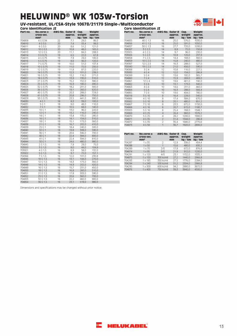
HELUWIND® WK 300w-Torsion 1,8/3kVUV-resistant, direct burial
PropertiesCable structureTechnical dataSpecial bare copper conductor, finestranded according to IEC 60228
Temperatur rangeflexing -35°C to +90°Cfixed installation -40°C to +90°Cinstallation -20°C to +90°C
UV-resistantmulti-climate operation
Special heat-resistant insulation black torsion testedJacket special heat-resistant compound flame-retardant
Operating temperature at conductormax. +90°C
Black jacket oil-resistantrecyclable
Nominal voltageaccording VDE U0/U 1,8/3kV
easy to assemblealso for direct burial
Test voltage 50 Hz:9000 V NoteMinimum bending radius10 x cable diameter(5 x for fixed installation)
Other diameters, part-no. and prices onrequest.Please contact us with your individualrequirements viafax +49 7150 9209 5135.
Torsion application+/-100° per 1m for unshielded versionFlame testFT1, VW-1, IEC 60332-1 flame retardant andself-extinguishing
ApplicationThe WK 300w was designed for flexible use, especially to accommodate the torsional stress in the cable loop of a wind turbine. The WK serieswas successfully tested with over 18,000 torsion cycles and thus offers optimal functional safety well beyond the service life of the windturbine. An additional feature is the high voltage level of 1.8/3kV. The WK300w is also designed for flexible routing through empty conduitand underground installation. It can be used, for example, in the power cabling of inverter cabinets to external transformer stations. Witha circuit temperature of +90° degrees Celsius, a high current-carrying capacity is possible.
Weightapprox.kg / km
Cop.weightkg / km
Outer Øapprox.mm
AWG-No.No.cores xcross-sec.mm²
Part no. Weightapprox.kg / km
Cop.weightkg / km
Outer Øapprox.mm
AWG-No.No.cores xcross-sec.mm²
Part no.
500,0336,014,8-1 x 35706432 1990,01440,025,9-1 x 150706403660,0480,016,6-1 x 50706399 2430,01776,028,7-1 x 185706404920,0672,019,5-1 x 70706400 2877,92304,031,2-1 x 240706405
1300,0912,023,9-1 x 95706401 3960,02880,032,0-1 x 3007064061600,01152,024,8-1 x 120706402 4800,03840,039,2-1 x 400706407
Dimensions and specifications may be changed without prior notice.

33
HELUWIND® WK 303w-Torsion 1,8/3kV,UL 2kVUV-resistant, direct burial
PropertiesCable structureTechnical dataSpecial bare copper conductor, finestranded according to IEC 60228
Temperatur rangeflexing -35°C to +90°Cfixed installation -40°C to +90°Cinstallation -20°C to +90°C
UV-resistantmulti-climate operation
Special heat-resistant insulation black torsion testedJacket special heat-resistant compound flame-retardant
Operating temperature at conductormax. +90°C
Black jacket oil-resistantrecyclable
Nominal voltageacc. VDE U0/U 1,8/3kVacc. UL 2000V
easy to assemblealso for direct burial
Test voltage 50 Hz:9000 V
NoteOther diameters, part-no. and prices onrequest.Please contact us with your individualrequirements viafax +49 7150 9209 5135.
Minimum bending radius10 x cable diameter(5 x for fixed installation)Torsion application+/-100° per 1m for unshielded versionFlame testIEC 60332-1, FT2
ApplicationThe HELUWIND® WK 303 series was specifically designed for wind power applications.We supply the leading wind turbine manufacturers withour cables.
= The product conforms to the EC low-voltage directive 73/23EWG bzw. 93/68EWG.
Weightapprox.kg / km
Cop.weightkg / km
Outer Øapprox.mm
AWG-No.No.cores xcross-sec.mm²
Part no. Weightapprox.kg / km
Cop.weightkg / km
Outer Øapprox.mm
AWG-No.No.cores xcross-sec.mm²
Part no.
1820,01440,027,1300 kcmil1 x 150708874 3170,02304,032,0500 kcmil1 x 2407088762360,01776,029,2350 kcmil1 x 185708875 3820,02880,034,2600 kcmil1 x 300708877
Dimensions and specifications may be changed without prior notice.

34
HELUWIND® WK 305-Torsion 1,8/3kVUV-resistant, Offshore
PropertiesCable structureTechnical dataSpecial bare copper conductor, finestranded according to IEC 60228
Temperature rangeflexing -40 °C to +90 °Cfixed installation -40 °C to +90 °C
halogen freeextremely abrasion resistant
Special insulation black low adhesionOperating temperature at conductormax. +90°C
Jacket SSH compound low adhesion high flame retardantBlack jacket torsion testet
Nominal voltageto VDE U0/U 1,8/3kV
suitable for offshoreextremely oil resistant
Test voltage 50 Hz9000 V
UV resistantrecyclable
Minimum bending radius10 x cable diameter(5 x for fixed installation)
Multi climate operationdesigned for CCV applicationeasy to assemble
Torsion application+/-100° per 1m NoteFlame testIEC 60332-3, FT2 Other diameters, part-no. and prices on
request.Please contact us with your individualrequirements viafax +49 7150 9209 5135.
Halogen freeIEC 60754-1Smoke densityIEC 61034-1+2Oil testacc. to oil res II
ApplicationThe WK 305 was designed for flexible use, especially to accommodate the torsional stress in the cable loop of a wind turbine. The WK serieswas successfully tested with over 18,000 torsion cycles and thus offers optimal functional safety well beyond the service life of the windturbine. An additional feature is the high voltage level of 1.8/3kV. The WK 305 is used instead of the WK 300 when the absence of halogenis necessary.
Weightapprox.kg / km
Cop.weightkg / km
Outer Øapprox.mm
AWG-No.No.cores xcross-sec.mm²
Part no. Weightapprox.kg / km
Cop.weightkg / km
Outer Øapprox.mm
AWG-No.No.cores xcross-sec.mm²
Part no.
660,0480,015,0-1 x 50706452 2430,01776,031,4-1 x 185706457920,0672,020,0-1 x 70706453 3280,02304,034,4-1 x 240706458
1300,0912,023,8-1 x 95706454 3960,02880,036,9-1 x 3007064591600,01152,026,3-1 x 120706455 4800,03840,041,5-1 x 4007064601990,01440,029,2-1 x 150706456
Dimensions and specifications may be changed without prior notice.

35
HELUWIND® WK 335-Torsion 2,0/3,3kVUL 2kVUV-resistant, Offshore
PropertiesCable structureTechnical dataSpecial bare copper conductor, finestranded according to IEC 60228
Temperatur rangeflexing -40°C to +90°Cfixed installation -40°C to +90°C
halogen-freeglobal application
Special insulation black extremely abrasion resistantOperating temperature at conductormax. +90°C
Jacket SSH compound low adhesion low adhesionBlack jacket high flame retardant
Nominal voltageacc. VDE U0/U 2,0/3,3kV,acc. UL 2000V
torsion testetsuitable for Offshoreextremely oil resistant
Test voltage 50 Hz:9000 V
UV resistantrecyclable
Minimum bending radius10 x cable diameter(5 x for fixed installation)
Multi climate operationdesigned for CCV applicationeasy to assemble
Torsion application+/-100° per 1m
NoteFlame testIEC 60332-3, FT2 Other diameters, part-no. and prices on
request.Please contact us with your individualrequirements viafax +49 7150 9209 5135.
Halogen-freeIEC 60754-1Smoke densityIEC 61034-1+2Oil testacc. to oil res II
ApplicationThe HELUWIND® WK 335 series was specifically designed for wind power applications. We supply the leading wind turbine manufacturerswith our cables.
Weightapprox.kg / km
Cop.weightkg / km
Outer Øapprox.mm
AWG-No.No.cores xcross-sec.mm²
Part no. Weightapprox.kg / km
Cop.weightkg / km
Outer Øapprox.mm
AWG-No.No.cores xcross-sec.mm²
Part no.
1810,01260,026,34/01 x 120708340 3270,02404,032,4500 kcmil1 x 2407083431920,01540,027,5300 kcmil1 x 150708341 3920,02980,034,6600 kcmil1 x 3007083442460,01876,029,6350 kcmil1 x 185708342
Dimensions and specifications may be changed without prior notice.

36
HELUWIND® WK MS-Single-Torsion3,6/6kV, 12/20kV
PropertiesCable structureTechnical dataSpecial bare copper conductor, finestranded acc. to IEC 60228
Temperatur rangeflexing -40°C to +90°C
abrasion resistantflame retardant
Special semiconductor layerNominal voltage3,6/6 kV12/20 kV
torsion testetSpecial insulation black oil resistantJacket special rubber compound UV resistant
Minimum bending radius12 x cable diameter
Black jacket multi climate operationdesigned for CCV application
Torsion application+/-105° per 1m
easy to assemble
NoteOther diameters, part-no. and prices onrequest.Please contact us with your individualrequirements viafax +49 7150 9209 5135.
12/20kV3,6/6kVWeightapprox.kg / km
Cop.weightkg / km
Outer Øapprox.mm
AWG-No.No.cores xcross-sec.mm²
Part no. Weightapprox.kg / km
Cop.weightkg / km
Outer Øapprox.mm
AWG-No.No.cores xcross-sec.mm²
Part no.
1640,01152,025,2-1 x 120708711 1860,01152,027,3-1 x 1207087121820,01440,027,1-1 x 150708332 2090,01440,029,5-1 x 1507087132360,01776,029,2-1 x 185708333 2530,01776,031,6-1 x 1857087143170,02304,032,0-1 x 240708334 3420,02304,034,7-1 x 2407087153820,02880,034,2-1 x 300708335 4100,02880,036,8-1 x 300708716
Dimensions and specifications may be changed without prior notice.

37
HELUWIND® WK MS-Single-Torsion UL/CSA3,6/6kV, 12/20kV
PropertiesCable structureTechnical dataSpecial bare copper conductor, finestranded acc. to IEC 60228
Temperatur rangeflexing -40°C to +90°C
abrasion resistantflame retardant
Special semiconductor layerNominal voltage3,6/6 kV12/20 kV
torsion testetSpecial insulation black oil resistantCopper shield UV resistant
Minimum bending radius12 x cable diameter
Jacket special rubber compound multi climate operationBlack jacket designed for CCV application
Torsion application+/-105° per 1m
easy to assemble
ApprovalUL 1072 Note
Other diameters, part-no. and prices onrequest.Please contact us with your individualrequirements viafax +49 7150 9209 5135.
12/20kV3,6/6kVWeightapprox.kg / km
Cop.weightkg / km
Outer Øapprox.mm
AWG-No.No.cores xcross-sec.mm²
Part no. Weightapprox.kg / km
Cop.weightkg / km
Outer Øapprox.mm
AWG-No.No.cores xcross-sec.mm²
Part no.
1790,01280,024,1262 kcmil708702 1990,01280,026,1262 kcmil7087172191,01590,027,2313 kcmil7087182072,01590,025,5313 kcmil708703
2376,01900,027,8373 kcmil708704 2563,01900,029,8373 kcmil7087192983,02272,031,9444 kcmil7087202770,02272,029,9444 kcmil708705
3246,02608,032,7535 kcmil708706 3471,02608,034,9535 kcmil7087214020,03300,037,2646 kcmil7087223801,03300,035,1646 kcmil708707
4492,03970,037,3777 kcmil708708 4696,03970,039,4777 kcmil7087235552,04780,042,4929 kcmil7087245344,04780,040,1929 kcmil708709
6410,05690,044,21111kcmil
708710 6620,05690,046,51111kcmil
708725
Dimensions and specifications may be changed without prior notice.

38
HELUWIND® WK MS-Multi-Torsion3,6/6kV, 12/20kV, 24/38kV
PropertiesCable structureTechnical dataSpecial bare copper conductor, finestranded acc. to IEC 60228
Temperatur rangeflexing -40°C to +90°C
global applicationabrasion resistant
Special semiconductor layerNominal voltage3,6/6 kV,12/20 kVor 24/38 kV
flame retardantSpecial insulation black torsion testetConductor insulation with semiconductorlayer
oil resistantUV resistant
Minimum bending radius12 x cable diameter
conductors wrapped multi climate operationInner Sheath special compound designed for CCV application
Torsion application+/-105° per 1m
Sheath special rubber compound easy to assembleBlack jacket
NoteOther diameters, part-no. and prices onrequest.Please contact us with your individualrequirements viafax +49 7150 9209 5135.
12/20kV3,6/6kVWeightapprox.kg / km
Cop.weightkg / km
Outer Øapprox.mm
AWG-No.No.cores xcross-sec.mm²
Part no. Weightapprox.kg / km
Cop.weightkg / km
Outer Øapprox.mm
AWG-No.No.cores xcross-sec.mm²
Part no.
2600,0960,040,1-3 x 25 + 25708425 3231,01344,047,0-3 x 35 + 357087273020,01344,045,1-3 x 35 + 35708426 4421,02688,054,0-3 x 70 + 707087293500,01920,047,2-3 x 50 + 50708427
24/38kV4210,02688,051,9-3 x 70 + 70708428Weightapprox.kg / km
Cop.weightkg / km
Outer Øapprox.mm
AWG-No.No.cores xcross-sec.mm²
Part no.12/20kV
Weightapprox.kg / km
Cop.weightkg / km
Outer Øapprox.mm
AWG-No.No.cores xcross-sec.mm²
Part no.2910,0960,043,6-3 x 25 + 257087303400,01344,048,9-3 x 35 + 35708731
2790,0960,041,9-3 x 25 + 25708726 3921,01920,051,2-3 x 50 + 507087323711,01920,049,3-3 x 50 + 50708728 4638,02688,056,0-3 x 70 + 70708733
Dimensions and specifications may be changed without prior notice.

39
HELUWIND® WK MS-Multi-Torsion UL/CSA3,6/6kV, 12/20kV, 24/38kV
PropertiesCable structureTechnical dataSpecial bare copper conductor, finestranded acc. to IEC 60228
Temperatur rangeflexing -40°C to +90°C
global applicationabrasion resistant
Special semiconductor layerNominal voltage3,6/6 kV,12/20 kVor 24/38 kV
flame retardantSpecial insulation EOR or AVGM torsion testetConductor insulation with semiconductorlayer for N-conductor
suitable for Offshoreoil resistant
Minimum bending radius12 x cable diameter
conductors wrapping UV resistanttinned copper shield multi climate operation
Torsion application+/-105° per 1m
Inner jacket special compound designed for CCV applicationjacket special halogen free compound easy to assemble
ApprovalUL 1072
Black jacket
NoteOther diameters, part-no. and prices onrequest.Please contact us with your individualrequirements viafax +49 7150 9209 5135.
12/20kV3,6/6kVWeightapprox.kg / km
Cop.weightkg / km
Outer Øapprox.mm
AWG-No.No.cores xcross-sec.mm²
Part no. Weightapprox.kg / km
Cop.weightkg / km
Outer Øapprox.mm
AWG-No.No.cores xcross-sec.mm²
Part no.
2600,0960,040,13x4+4708734 3711,01920,049,33x1+17087403020,01344,045,13x2+2708735 4421,02688,054,03x2/0+2/07087413500,01920,047,23x1+1708736
24/38kV4210,02688,051,93x2/0+2/0708737Weightapprox.kg / km
Cop.weightkg / km
Outer Øapprox.mm
AWG-No.No.cores xcross-sec.mm²
Part no.12/20kV
Weightapprox.kg / km
Cop.weightkg / km
Outer Øapprox.mm
AWG-No.No.cores xcross-sec.mm²
Part no.2910,0960,043,63x4+47087423400,01344,048,93x2+2708743
2790,0960,041,93x4+4708738 3921,01920,051,23x1+17087443231,01344,047,03x2+2708739 4638,02688,056,03x2/0+2/0708745
Dimensions and specifications may be changed without prior notice.

40
HELUWIND® WK DLO 2kVFT4, RHH, RHW-2, UL44 , VW-1, LS, MSHA
PropertiesCable structureTechnical dataTinned copper conductors according toASTM B-172, ASTM B-33
Temperature range:flexing -40°C to +90°C
UV-resistant
Special wrappingNominal voltage:DLO 2000V
NoteOther diameters, part-no. and prices onrequest.Please contact us with your individualrequirements viafax +49 7150 9209 5135.
Special EPR insulationApprovals:UL44, CSA, ICEA S-68-516/NEMA WC-8,MSHA, VW-1, FOR CT USE. LS CERTIFIED
Special CPE jacket compound, non-adhesiveJacket color black
Flame testFT4, FT1
ApplicationThe cable is listed under the standard UL 44. The WK DLO is a flexible cable for the universal tower wiring of the wind turbine all the way upto the top tower segment. Optional, we can produce a version for torsional application. We recommend our WK 103 or WK 135 as a torsioncable through the cable loop to the generator in the nacelle.
Weightapprox.kg / km
Cop.weightkg / km
Outer Øapprox.mm
AWG-No.No.cores xcross-sec.mm²
Part no. Weightapprox.kg / km
Cop.weightkg / km
Outer Øapprox.mm
AWG-No.No.cores xcross-sec.mm²
Part no.
37,022,05,914703156 1298,01103,021,74/07028631590,01280,024,8262 kcmil70251469,033,06,312703157
100,061,07,210703158 2176,01900,028,2373 kcmil7031661872,01590,026,4313 kcmil703165142,082,88,28702513
200,0140,010,16703159 2176,01900,028,2373 kcmil7088572570,02272,030,0444 kcmil703167286,0237,011,54703160
370,0339,012,62703161 3046,02608,032,2535 kcmil7025153600,03300,034,8646 kcmil703168637,0510,016,11703162
715,0465,017,51/0703163 4290,03970,037,0777 kcmil7031695144,04780,039,5929 kcmil703170830,0656,018,52/0703862
1104,0930,020,23/0703164 6070,05690,044,41111kcmil
703171
Dimensions and specifications may be changed without prior notice.

41
HELUWIND® WK RHH/RHW-2 ALUUL44, NEC
PropertiesCable structureTechnical dataSpecial compacted ALU conductorsaccording to AA-8000
Temperature range:flexing -40°C to +90°C
UV-resistantflame resistant
Special XLPE insulationNominal voltage:2000V
reduced outer diametercolor black
Approvals:UL listet as RHH/RHW-2UL44NEC
NoteOther diameters, part-no. and prices onrequest.Please contact us with your individualrequirements viafax +49 7150 9209 5135.
Weightapprox.kg / km
ALweightkg / km
Outer Øapprox.mm
AWG-No.No.cores xcross-sec.mm²
Part no. Weightapprox.kg / km
ALweightkg / km
Outer Øapprox.mm
AWG-No.No.cores xcross-sec.mm²
Part no.
541,0367,023,2262 kcmil708746 1210,0905,034,0646 kcmil7087511510,01088,036,1777 kcmil708752630,0439,024,3313 kcmil708747
741,0523,026,9373 kcmil708748 1720,01301,039,5929 kcmil7087531900,01556,043,21111
kcmil708754780,0622,028,6444 kcmil708749
960,0749,031,6535 kcmil708750
Dimensions and specifications may be changed without prior notice.

42

43
HELUWIND® WK POWERLINE ALU 105°C, 0,6/1kVflexible ALU-Conductor
PropertiesCable structureTechnical dataAluminium conductor, fine stranded wiresTemperature range
fixed -40°C to +105°Cflexing -20°C up to +90°C
UV resistantoil-resistantSpecial insulation black
Sheath special compound easy to assembleOperating temperature at conductormax. +105°C
recyclableblack jacket
Nominal voltage 0,6/1kV (50Hz)
NotePlease ask for our extendednotes/informationabout the properties and for the necessaryconnection technology.Please contact us with your individualrequirements viafax +49 7150 9209 5135.
Test voltage2,5kV (50Hz)Min. bending radiusflexing 10 x cable outer diameterfixed installation 4 x cable outer diameterFlame testIEC 60332-1Approvalsacc. to DIN VDE 0250-813UL/CSA in preparation
ApplicationThe WK Powerline ALU is a highly flexible aluminum cable with a fine wire strand structure, which is suitable for use in the area of energymanagement - especially in the power wiring of a wind turbine. Thanks to its high flexibility and low weight, this cable can be installed inthe tower in one continuous length. Time-intensive wiring of the individual tower segments is eliminated.
The decisive advantage, however, lies in the process safety of the connection technology: The number of breaks from the top tower segmentto the inverter is reduced from as many as 90 connection points to only 18 connections, depending on the number of power cables andtower segments. The installation effort in the field is thereby reduced from several days to a few hours.
For torsional use we recommend the WK 103-T, WK 135-T or WK 137-T.
The WK Powerline ALU may only be prepared with the certified connection technology of HELUKABLE®. Either with the C8Crimp or screw connector (tested in accordance with IEC 61238-1 Cl. A). See Accessories section in the catalog.The cable is also optionally available in a halogen-free design with UL/CSA approval and a rated voltage of 1.8/3 kV.
= The product conforms to the EC Low Voltage Directive 2006/95/EC
Weightapprox.kg / km
ALweightkg / km
Outer Øapprox.mm
AWG-No.No.cores xcross-sec.mm²
Part no. Weightapprox.kg / km
ALweightkg / km
Outer Øapprox.mm
AWG-No.No.cores xcross-sec.mm²
Part no.
379,0206,017,4-1 x 70707062 950,0544,024,5-1 x 185706088480,0280,018,8-1 x 95707063 1150,0706,027,5-1 x 240706089576,0355,020,6-1 x 120707064 1400,0882,031,9-1 x 300706084665,0441,022,4-1 x 150706408 1680,01176,036,7-1 x 400706085
Dimensions and specifications may be changed without prior notice.

44
HELUWIND® WK POWERLINE ALU robust 105°C,0,6/1kVflexible ALU-Conductor
PropertiesCable structureTechnical dataAluminium conductor, fine stranded wiresTemperature range
fixed -40°C to +105°Cflexing -20°C up to +90°C
extremely abraison resistantUV resistantSpecial insulation black
Sheath special compound oil-resistantOperating temperature at conductormax. +105°C
easy to assembleblack jacketrecyclable
Nominal voltage 0,6/1kV (50Hz) NoteTest voltage2,5kV (50Hz)
Please ask for our extendednotes/informationabout the properties and for the necessaryconnection technology.Please contact us with your individualrequirements viafax +49 7150 9209 5135.
Min. bending radiusflexing 10 x cable outer diameterfixed installation 4 x cable outer diameterFlame testIEC 60332-1Approvalsacc. to DIN VDE 0250-813UL/CSA in preparation
Application
= The product conforms to the EC low-voltage directive 2006/95/EG.
Weightapprox.kg / km
ALweightkg / km
Outer Øapprox.mm
AWG-No.No.cores xcross-sec.mm²
Part no. Weightapprox.kg / km
ALweightkg / km
Outer Øapprox.mm
AWG-No.No.cores xcross-sec.mm²
Part no.
460,0206,017,4-1 x 70707097 950,0544,024,5-1 x 185707101536,0280,018,8-1 x 95707098 1150,0706,027,5-1 x 240707102576,0355,020,6-1 x 120707099 1398,0882,031,9-1 x 300707103665,0441,022,4-1 x 150707100 1588,01176,036,7-1 x 400707104
Dimensions and specifications may be changed without prior notice.
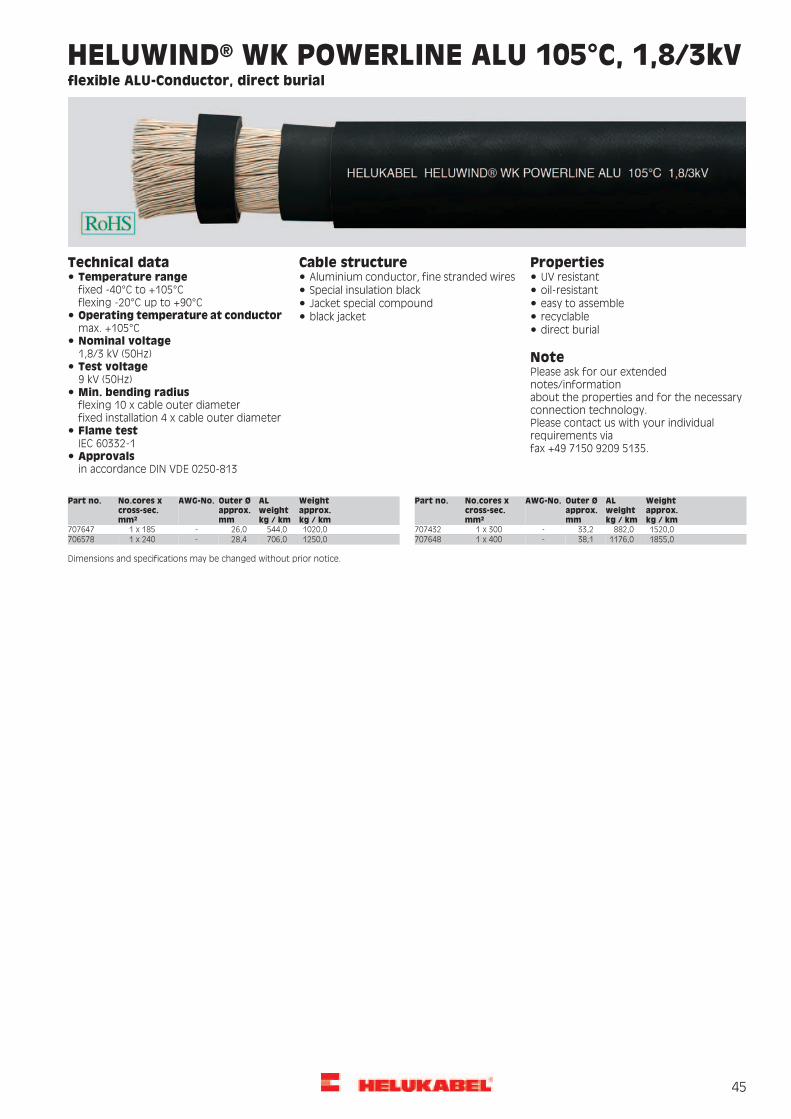
45
HELUWIND® WK POWERLINE ALU 105°C, 1,8/3kVflexible ALU-Conductor, direct burial
PropertiesCable structureTechnical dataAluminium conductor, fine stranded wiresTemperature range
fixed -40°C to +105°Cflexing -20°C up to +90°C
UV resistantoil-resistantSpecial insulation black
Jacket special compound easy to assembleOperating temperature at conductormax. +105°C
recyclableblack jacketdirect burial
Nominal voltage 1,8/3 kV (50Hz) NoteTest voltage9 kV (50Hz)
Please ask for our extendednotes/informationabout the properties and for the necessaryconnection technology.Please contact us with your individualrequirements viafax +49 7150 9209 5135.
Min. bending radiusflexing 10 x cable outer diameterfixed installation 4 x cable outer diameterFlame testIEC 60332-1Approvalsin accordance DIN VDE 0250-813
Weightapprox.kg / km
ALweightkg / km
Outer Øapprox.mm
AWG-No.No.cores xcross-sec.mm²
Part no. Weightapprox.kg / km
ALweightkg / km
Outer Øapprox.mm
AWG-No.No.cores xcross-sec.mm²
Part no.
1020,0544,026,0-1 x 185707647 1520,0882,033,2-1 x 3007074321250,0706,028,4-1 x 240706578 1855,01176,038,1-1 x 400707648
Dimensions and specifications may be changed without prior notice.

46
HELUWIND® WK POWERLINE ALU robust 105°C,1,8/3kVflexible ALU-Conductor
PropertiesCable structureTechnical dataAluminium conductor, fine stranded wiresTemperature range
fixed -40°C to +105°Cflexing -20°C up to +90°C
extremely abraison resistantUV resistantSpecial insulation black
Sheath special compound oil-resistantOperating temperature at conductormax. +105°C
easy to assembleblack jacketrecyclable
Nominal voltage 1,8/3kV (50Hz) NoteTest voltage9kV (50Hz)
Please ask for our extendednotes/informationabout the properties and for the necessaryconnection technology.Please contact us with your individualrequirements viafax +49 7150 9209 5135.
Min. bending radiusflexing 10 x cable outer diameterfixed installation 4 x cable outer diameterFlame testIEC 60332-1Approvalsin accordance DIN VDE 0250-813
Weightapprox.kg / km
ALweightkg / km
Outer Øapprox.mm
AWG-No.No.cores xcross-sec.mm²
Part no. Weightapprox.kg / km
ALweightkg / km
Outer Øapprox.mm
AWG-No.No.cores xcross-sec.mm²
Part no.
1020,0544,026,0-1 x 185707692 1520,0882,033,2-1 x 3007076941250,0706,028,4-1 x 240707693 1855,01176,038,1-1 x 400707695
Dimensions and specifications may be changed without prior notice.
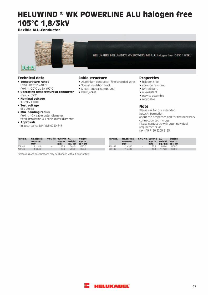
47
HELUWIND ® WK POWERLINE ALU halogen free105°C 1,8/3kVflexible ALU-Conductor
PropertiesCable structureTechnical dataAluminium conductor, fine stranded wiresTemperature range
fixed -40°C to +105°Cflexing -20°C up to +90°C
halogen freeabraison resistantSpecial insulation black
Sheath special compound UV resistantOperating temperature at conductormax. +105°C
oil-resistantblack jacketeasy to assemble
Nominal voltage 1,8/3kV (50Hz)
recyclable
Test voltage9kV (50Hz)
NotePlease ask for our extendednotes/informationabout the properties and for the necessaryconnection technology.Please contact us with your individualrequirements viafax +49 7150 9209 5135.
Min. bending radiusflexing 10 x cable outer diameterfixed installation 4 x cable outer diameterApprovalsin accordance DIN VDE 0250-813
Weightapprox.kg / km
ALweightkg / km
Outer Øapprox.mm
AWG-No.No.cores xcross-sec.mm²
Part no. Weightapprox.kg / km
ALweightkg / km
Outer Øapprox.mm
AWG-No.No.cores xcross-sec.mm²
Part no.
1020,0544,026,0-1 x 185709143 1400,0882,033,2-1 x 3007091451150,0706,028,4-1 x 240709144 1680,01176,038,1-1 x 400709146
Dimensions and specifications may be changed without prior notice.

48
HELUWIND® WK P Copper Tower0,6/1kV
PropertiesCable structureTechnical dataBare copper stranded round shapedconductors (RM)according to IEC 60228, Cl. 2 (nv)
Temperature rangefixed -40°C to +90°Cflexing -25°C up to +50°C
UV resistantoil-resistant
insulation EPR compound blackOperating temperature at conductormax. +90°C
NotePlease contact us with your individualrequirements viafax +49 7150 9209 5135.
Jacket special PCP compoundNominal voltage 0,6/1kV (50Hz)
Jacket color black
Test voltage4kV (50Hz)Min. bending radius15 x cable diameterApprovalsin accordance DIN to IEC 60502-1
ApplicationFor use for medium mechanical stress in dry, damp, wet rooms and outdoor, especially as power cable in wind turbines, for fixed installationin the tower or lattice tower. Because of the special cable structure, and outer jacket, this cable provides a relative flexibility compared tostandard cables. (NYY-N2XY-N2XH). Optionally as 1,8/3kV.
Weightapprox.kg / km
Cop.weightkg / km
Outer Øapprox.mm
AWG-No.No.cores xcross-sec.mm²
Part no. Weightapprox.kg / km
Cop.weightkg / km
Outer Øapprox.mm
AWG-No.No.cores xcross-sec.mm²
Part no.
1610,01440,023,6-1 x 150708475 3200,02880,030,0-1 x 3007084782050,01776,025,0-1 x 185708476 4150,03840,034,0-1 x 4007084792630,02304,028,0-1 x 240708477
Dimensions and specifications may be changed without prior notice.
= The product conforms to the EC low-voltage directive 2006/95/EG.
OWERLINE

49
HELUWIND® WK POWERLINE ALU Tower0,6/1 kV
PropertiesCable structureTechnical dataALU stranded round shaped conductors(RM)according to IEC 60228, Cl. 2 (nv)
Temperature rangefixed -40°C to +90°Cflexing -25°C to +50°C
UV resistantoil-resistant
insulation EPR compound blackOperating temperature at conductormax. +90°C
NotePlease contact us with your individualrequirements viafax +49 7150 9209 5135.
Jacket special PCP compoundNominal voltage 0,6/1kV (50Hz)
Jacket color black
Test voltage, 50 Hz4 kV (50Hz)Min. bending radius15 x cable diameterApprovalsaccording to IEC 60502-1
ApplicationFor use for medium mechanical stress in dry, damp, wet rooms and outdoor, especially as power cable in wind turbines, for fixed installationin the tower or lattice tower. Because of the special cable structure, and outer jacket, this cable provides a relative flexibility compared tostandard cables. (NYY-N2XY-N2XH). Optionally as 1,8/3kV.
Weightapprox.kg / km
ALweightkg / km
Outer Øapprox.mm
AWG-No.No.cores xcross-sec.mm²
Part no. Weightapprox.kg / km
ALweightkg / km
Outer Øapprox.mm
AWG-No.No.cores xcross-sec.mm²
Part no.
790,0435,023,0-1 x 150708470 1342,0870,029,0-1 x 300708473960,0537,026,0-1 x 185708471 1843,01160,031,4-1 x 400708474
1208,0696,027,0-1 x 240708472
Dimensions and specifications may be changed without prior notice.
= The product conforms to the EC low-voltage directive 2006/95/EG.

50
HELUWIND® WK POWERLINE Blade Copperlightning protection
PropertiesCable structureTechnical dataBare Copper conductor RMTemperature range
fixed installation -40°C to +80°Coil resistantUV-resistantSpecial insulation compound
Nominal voltage0,6/1kV (50 Hz) Note
Jacket color black
Test voltage4kV (50 Hz)
Please contact us with your individualrequirements viafax +49 7150 9209 5135.Min. bending radius
fixed installation 4 x cable diameter
Application= The product conforms to the EC low-voltage directive 2006/95/EG.
Weightapprox.kg / km
Cop.weightkg / km
Outer Øapprox.mm
AWG-No.No.cores xcross-sec.mm²
Part no. Weightapprox.kg / km
Cop.weightkg / km
Outer Øapprox.mm
AWG-No.No.cores xcross-sec.mm²
Part no.
690,0480,012,1-1 x 50708678 1050,0672,013,7-1 x 70708679
Dimensions and specifications may be changed without prior notice.

51
HELUWIND® WK POWERLINE Blade ALUlightning protection
PropertiesCable structureTechnical dataAluminium conductor RMTemperature range
fixed installation -40°C to +80°Coil resistantUV-resistantSpecial insulation compound
Nominal voltage0,6/1kV (50 Hz) Note
Sheath color black
Test voltage4kV (50 Hz)
Please contact us with your individualrequirements viafax +49 7150 9209 5135.Min. bending radius
fixed installation 4 x cable diameter
Application
= The product conforms to the EC low-voltage directive 2006/95/EG.
Weightapprox.kg / km
ALweightkg / km
Outer Øapprox.mm
AWG-No.No.cores xcross-sec.mm²
Part no. Weightapprox.kg / km
ALweightkg / km
Outer Øapprox.mm
AWG-No.No.cores xcross-sec.mm²
Part no.
376,0148,012,1-1 x 50706576 491,0208,013,7-1 x 70706577
Dimensions and specifications may be changed without prior notice.

52
NYY-J / NYY-O power cable, 0,6/1kV, VDE approved
PropertiesCable structureTechnical dataPlain copper conductor, to DIN VDE 0295cl. 1 or cl. 2 solid or stranded type, BS 6360cl. 1 or cl. 2, IEC 60228 and HD 383
Power and control cable to DIN VDE 0276part 603 S1, HD 603.1 and IEC 60502,7 core and above to DIN VDE 0276 part 627,HD 627 S1 and IEC 60502
PVC self-extinguishing and flame retardantaccording to VDE 0482-332-1-2, DIN EN60332-1-2/ IEC 60332-1 (equivalentDIN VDE 0472 part 804 test method B)PVC core insulation, DIV4 to HD 603.1The materials used in manufacture arecadmium-free and contain no silicone and
Temperature rangeflexing -5 °C to +50 °Cfixed installation -40 °C to +70 °C
Cores stranded concentricallyColour coded to DIN VDE 0293-308, 0276part 603 or HD 186 free from substances harmful to the
wetting properties of lacquersPermissible operating temperatureat conductor +70 °C
Core colour for 3+ conductorJ-type: gnye ( ), bn, bk, gyO-type: bu ( ), bn, bk, gy
Highest permissible voltageDirect current systems 1,8 kVPermissible short circuit temperature
+160 °C (short circuit duration 5 sec.) Alternating current systems,single-phase systems 1,4 kVBoth conductors insulated,single-phase systems 0,7 kVOne conductor earthed,three-phase systems 1,2 kVWith concentric conductor anda cross-section of 240 mm²and above 3,6 kV
PVC outer jacket, DMV5 to HD 603.1Nominal voltage U0/U 0,6/1 kV Sheath colour blackTest voltage 4 kVMax. permissible tensile stress withcable grip for Cu-conductor= 50 N/mm²Minimum bending radiusfor single core approx. 15x cable øfor multi core approx. 12x cable øPower ratings tablesee Technical Informations NoteCaloric load valuessee Technical Informations
re = round conductor, single-wire;rm = round conductor, multiple-wire;sm = stranded, sectional core.Also available in NYFGBY, NYBY versions etc.2 cores = adapted to DIN VDE.In respect to 3+ conductorsWhereby only one conductor is allowed tocontain a smaller cross-section (as perDIN VDE 0276 part 603 table 5) andpermitted to place as insulated core(gree-yellow and blue as -conductor),stranded in layer.
ApplicationPower cables for energy supply are installed in open air, in underground, in water, indoors, in cable ducts, power stations, for industry anddistribution boards as well as in subscriber networks, where mechanical damages are not to be expected.
= The product is conformed with the EC Low-Voltage Directive 2006/95/EG.
AWG-No.O typePart no.
AWG-No.J typePart no.
Weightapprox.kg / km
Cop.weightkg / km
Outer Øapprox. mm
No.cores xcross-sec.mm²
12320891232001115,038,09,0re1 x 410320901032002135,058,09,5re1 x 6832091832003179,096,010,0re1 x 10632092632004245,0154,011,0re1 x 16432093432005360,0240,012,0rm1 x 25232094232006470,0336,013,0rm1 x 35132095132007620,0480,015,0rm1 x 50
2/0320962/032008810,0672,016,5rm1 x 703/0320973/0320091110,0912,019,0rm1 x 954/0320984/0320101360,01152,020,5rm1 x 120
300 kcmil32099300 kcmil320111670,01440,022,5rm1 x 150350 kcmil32100350 kcmil320122050,01776,025,0rm1 x 185500 kcmil32101500 kcmil320132630,02304,028,0rm1 x 240600 kcmil32102600 kcmil320143200,02880,030,0rm1 x 300750 kcmil32103750 kcmil320154150,03840,034,0rm1 x 400
1000 kcmil325581000 kcmil325565200,04800,038,0rm1 x 500-32559-325576650,06048,043,0rm1 x 630
Continuation Prices on request

53
NYY-J / NYY-O power cable, 0,6/1kV, VDE approved
AWG-No.O typePart no.
AWG-No.J typePart no.
Weightapprox.kg / km
Cop.weightkg / km
Outer Øapprox. mm
No.cores xcross-sec.mm²
16321041632016175,029,011,0re2 x 1,514321051432017215,048,012,0re2 x 2,512321061232018295,077,014,0re2 x 410321071032019370,0115,015,0re2 x 6
832108832020495,0192,016,5re2 x 10632109632021670,0307,018,5re2 x 16432110432022960,0480,023,5rm2 x 25
16321111632023195,043,011,5re3 x 1,514321121432024250,072,012,5re3 x 2,512321131232025340,0115,014,0re3 x 410321141032026430,0173,015,0re3 x 6
832115832027590,0288,017,0re3 x 10632116632028820,0461,019,0re3 x 164321174320291320,0720,024,0rm3 x 252321182320301450,01008,025,0sm3 x 351321191320311850,01440,026,5sm3 x 50
2/0321202/0320322450,02016,030,0sm3 x 703/0321213/0320333300,02736,034,5sm3 x 954/0321224/0320344100,03456,037,0sm3 x 120
300 kcmil32296300 kcmil322934900,04320,040,0sm3 x 150350 kcmil32297350 kcmil322946500,05328,046,0sm3 x 185500 kcmil32298500 kcmil322958300,06912,051,0sm3 x 240
16321321632044230,058,012,0re4 x 1,514321331432045300,096,013,5re4 x 2,512321341232046410,0154,015,0re4 x 410321351032047520,0230,016,5re4 x 6
832136832048730,0384,018,5re4 x 106321376320491045,0614,021,5re4 x 164321384320501640,0960,026,0rm4 x 252321392320511760,01344,027,5sm4 x 351321401320522350,01920,030,0sm4 x 50
2/0321412/0320533100,02688,034,0sm4 x 703/0321423/0320544250,03648,039,0sm4 x 954/0321434/0320555300,04608,042,5sm4 x 120
300 kcmil32144300 kcmil320566400,05760,047,5sm4 x 150350 kcmil32145350 kcmil320578500,07104,052,0sm4 x 185500 kcmil32146500 kcmil3205811000,09216,058,0sm4 x 240
16321471632059270,072,013,0re5 x 1,514321481432060360,0120,014,5re5 x 2,512321491232061490,0192,016,5re5 x 410321501032062600,0288,018,0re5 x 6
832151832063890,0480,020,0re5 x 106321526320641255,0768,022,5re5 x 16
4320651960,01200,028,0rm5 x 252323002400,01680,034,0rm5 x 351322573500,02400,040,0rm5 x 50
16321531632066310,0101,015,5re7 x 1,510321631432076450,0168,016,5re7 x 2,5
1232086640,0269,018,5re7 x 410321741032087850,0403,020,0re7 x 6
8321758320881200,0672,023,5re7 x 1016321541632067380,0144,018,0re10 x 1,510321641432077520,0240,019,5re10 x 2,516321551632068420,0173,019,0re12 x 1,5
1432078600,0288,020,5re12 x 2,516321561632069470,0202,020,0re14 x 1,5
1432079680,0336,021,0re14 x 2,516321571632070520,0230,021,0re16 x 1,5
1432080750,0384,022,0re16 x 2,516321581632071570,0274,022,0re19 x 1,510321681432081850,0456,023,0re19 x 2,516321591632072650,0302,023,0re21 x 1,5
1432082980,0504,024,5re21 x 2,516321601632073750,0346,025,0re24 x 1,5
14320831100,0576,027,0re24 x 2,516321611632074860,0432,026,0re30 x 1,5
14320841280,0720,028,0re30 x 2,5163216216320751070,0576,029,0re40 x 1,5
14320851700,0960,031,5re40 x 2,514321692150,01248,035,0re52 x 2,516321761680,0878,034,0re61 x 1,5
3+1/2-conductorsAWG-No.O type
Part no.AWG-No.J type
Part no.Weightapprox.kg / km
Cop.weightkg / km
Outer Øapprox. mm
No.cores xcross-sec.mm²
4321234320351530,0874,024,5rm/re3 x 25 / 162321242320361750,01162,026,0sm/re3 x 35 / 161321251320372350,01680,029,0sm3 x 50 / 25
2/0321262/0320382850,02352,032,0sm/rm3 x 70 / 353/0321273/0320393850,03216,038,0sm3 x 95 / 504/0321284/0320404780,04128,041,0sm3 x 120 / 70
300 kcmil32129300 kcmil320415800,04992,046,0sm3 x 150 / 70350 kcmil32130350 kcmil320427600,06240,051,0sm3 x 185 / 95500 kcmil32131500 kcmil320439800,08064,058,0sm3 x 240 / 120
600 kcmil3225611500,010080,064,0sm3 x 300 / 150
Dimensions and specifications may be changed without prior notice. (RQ01) Prices on request

54
NAYY power cable, 0.6/1kV, VDE approved
Technical data
Temperature range
short circuit temperature
Nominal voltageTest voltage
tensile stress
Current carrying capacity
Minimum bending radius
Cable structure
Application
Part No. No.cores xcross-sec.mm²
Outer Øapp. mm
Alu weightkg / km
Weightapprox. kg / km
Properties
Highest permissible voltage
Note

55
Technical Data
Temperature range
Permissible operating temperature
Permissible short circuit temperature
Test voltage
Minimum bending radius
Cable Structure Properties
Highest permissible voltage
Note
NA2XY power cable 0.6/1kV, VDE approved
Application
No.cores xcross-sec.mm²
Outer Ø mm
Alu weight kg / km
Weightapprox. kg / km
J typePart No.
O typePart No.

N2XHpower cable, 0.6/1kV, halogen-free, no operational integrity
Technical data
Temperature range
operating temperature
Nominal voltageTest voltageMinimum bending radius
Radiation resistance
Caloric load values
Cable structure
LSZH
Application
Part No.J type
Part No.O type
No.cores xcross-sec.mm²
Outer Øapp. mm
Cop. weightkg / km
Weightapp. kg / km
Properties
Tests
Note

HELUWIND® WK (N)A2XH 0,6/1kV, halogen free
PropertiesCable structureTechnical dataALU conductors, stranded conductors acc.to IEC 60228 Cl. 2
Temperature rangefixed installation -40 °C to +90 °Cduring assembly -5 °C to +50 °C
Halogen-freeUV resistant
conductor insulation cross-linked PEOperating temperature at conductormax. +90°C
Core identification black NoteOther diameters, part-no. and prices onrequest.Please contact us with your individualrequirements viafax +49 7150 9209 5135.
Jacket thermoplastic polymerNominal voltageUo/U 0,6/1kV
black jacket
Test voltage 50 Hz4kVApprovalsproduction in according to VDE standards,CE compliantMin. bending radius15 x cable diameterFlame testacc. to DIN VDE 0482 part 266-2, BS 4066,part 3 / EN 50266-2 /IEC 60332-3-24 (acc. DIN VDE 0472part 804 cat. C)Smoke densityacc. DIN VDE 0482 part 268, HD 606,EN 50268-12 / IEC 61034-12,BS 7622 Teil 12 (acc. DIN VDE 0472 Teil 816)Corrosivity of combustion gasesacc. VDE 0482 Teil 267 /DIN EN 50267-2-2 / IEC 60754-2(acc. DIN VDE 0472 part 813)Halogen freeacc. DIN VDE 0482 part 267 / EN 50267-2-1/ IEC 60754-1(acc. DIN VDE 0472 part 815)
ApplicationThe HELUWIND® WK series was specifically designed for wind power applications.We supply the leading wind turbine manufacturers with ourcables.
= The product conforms to the EC low-voltage directive 2006/95/EG.
Weightapprox.kg / km
ALweightkg / km
Outer Øapprox.mm
AWG-No.No.cores xcross-sec.mm²
Part no. Weightapprox.kg / km
ALweightkg / km
Outer Øapprox.mm
AWG-No.No.cores xcross-sec.mm²
Part no.
1100,0537,022,0-1 x 185705031 1342,0870,026,9-1 x 3007050331208,0696,024,2-1 x 240705032 1843,01160,029,9-1 x 400705034
Dimensions and specifications may be changed without prior notice.

58
N2XS2Y 6/10kV, 12/20kV, 18/30kV XLPE-insulated,
Cu-conductor, single core, screened, PE-jacket
PropertiesCable structureTechnical dataCircular bare cu-conductor of strandedwires to HD 383
XLPE-insulated power cables to IEC 60502,DIN VDE 0276 part 620, HD 620 S1
The materials used in manufacture arecadmium-free and contain no silicone andfree from substances harmful to thewetting properties of lacquers
Temperature rangeduring installation up to -20 °C
Inner semi-conducting coatingCore insulation of cross-linked Polyethylene(XLPE), PE-compound DIX8 to HD 620.1 Installation notes
To guarantee an optimum on operatingreliability the extruded semi-conductive
Operating temperaturemax. 90 °C Outer extrusion of semi-conducting
coating spliced with the insulationShort circuit temperature250 °C (short circuit duration up to 5 sec.) layer is spliced with the insulation for long
duration. For this reason we recommenda peeling tool for installation.
Wrapping of conductive materialNominal voltagesU0/U 6/10 kV, 12/20 kV, 18/30 kV
Screen: Braiding of copper wires with oneor two tapes applied helically
Operating voltages for6/10 kV = max. 12 kV12/20 kV = max. 24 kV18/30 kV = max. 36 kV
WrappingNotePE-outer jacket black, compound DMP2 to
HD 620.1 Further dimensions available on request.Jacket colour black
Test voltages for6/10 kV = 15 kV12/20 kV = 30 kV18/30 kV = 45 kVMinimum bending radiusduring installation max. 15x cable øPower ratingstable see Technical Informations
ApplicationSuitable for indoor installation and in cable ducts, outdoors, underground and in water as well as for installation on cable trays for industries,switch-boards and power stations. The PE-outer jacket is resistant to high mechanical stress for laying the cables. This PE-jacket is notflame-resistant (does not conform the test method B, as per VDE 0472 part 804).The inner conducting layer between the conductor and the XLPE insulation and the firmly bonded outer conducting layer on the XLPEinsulation assures a construction free of partial discharges with high operational reliability.
N2XS2Y 6/10kVPart No. No. cores
x Cross-sec. mm2
Nominal- voltage kV
Outer Ø approx. mm
Cop. weight kg / km
Weightapprox. kg / km
32481 1x50 rm /16 6/10 26 662 152032482 1x70 rm /16 6/10 28 860 176032483 1x95 rm /16 6/10 29 1098 213032484 1x120 rm /16 6/10 31 1340 247032486 1x150 rm /25 6/10 33 1725 302032488 1x185 rm /25 6/10 35 2059 363032490 1x240 rm /25 6/10 37 42587 456032491 1x300 rm /25 6/10 38 3163 3630
Other dimensions available upon request. Dimensions and specifications may be changed without prior notice. Prices on request.

59
NA2XS2Y 6/10kV, 12/20kV, 18/30kV XLPE-insulated,
Cu-conductor, single core, screened, PE-jacket
PropertiesCable structureTechnical dataCircular bare alu-conductor of strandedwires to HD 383
XLPE-insulated power cables toDIN VDE 0276 part 620, HD 620 S1 andIEC 60502
The materials used in manufacture arecadmium-free and contain no silicone andfree from substances harmful to thewetting properties of lacquers
Inner semi-conducting coatingTemperature rangeduring installation up to -20 °C
Core insulation of cross-linked Polyethylene(XLPE), PE-compound DIX8 to HD 620.1 Installation notes
To guarantee an optimum on operatingreliability the extruded semi-conductive
Operating temperaturemax. 90 °C
Outer extrusion of semi-conductingcoating spliced with the insulation
layer is spliced with the insulation for longShort circuit temperature250 °C (short circuit duration up to 5 sec.)
Wrapping of conductive materialduration. For this reason we recommenda peeling tool for installation.
Screen: Braiding of copper wires with oneor two tapes applied helicallyNominal voltages
U0/U 6/10 kV, 12/20 kV, 18/30 kV
NoteWrapping
Operating voltages for6/10 kV = max. 12 kV12/20 kV = max. 24 kV18/30 kV = max. 36 kV
PE-outer jacket black, compound DMP2 toHD 620.1 Further dimensions available on request.Jacket colour black
Test voltages for6/10 kV = 15 kV12/20 kV = 30 kV18/30 kV = 45 kVMinimum bending radiusduring installation max. 15x cable øPower ratingstable see Technical Informations
ApplicationSuitable for indoor installation and in cable ducts, outdoors, underground and in water as well as for installation on cable trays for industries,switch-boards and power stations. The PE-outer jacket is resistant to high mechanical stress for laying the cables. This PE-jacket is notflame-resistant (does not conform the test method B, as per VDE 0472 part 804).The inner conducting layer between the conductor and the XLPE insulation and the firmly bonded outer conducting layer on the XLPEinsulation assures a construction free of partial discharges with high operational reliability.
NA2XS2Y 12/20kV
Part No. No. cores x Cross-sec. mm2
Nominal- voltage kV
Outer Ø approx. mm
Cop. weight kg/km
Alu weight kg / km
Weightapprox. kg / km
32534 1x70 rm /16 12/20 30 182 203 98032535 1x95 rm /16 12/20 33 182 276 112032536 1x120 rm /25 12/20 35 182 348 121032538 1x150 rm /25 12/20 37 283 435 142032540 1x185 rm /25 12/20 36 283 537 157032542 1x240 rm /25 12/20 40 283 696 183032543 1x300 rm /25 12/20 44 283 870 207032544 1x400 rm /35 12/20 47 394 1160 2460
Other dimensions available upon request. Dimensions and specifications may be changed without prior notice. Prices on request.
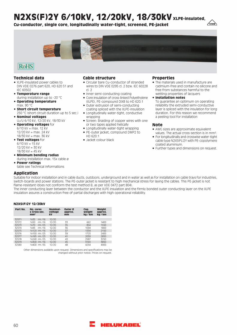
60
N2XS(F)2Y 6/10kV, 12/20kV, 18/30kV XLPE-insulated,
Cu-conductor, single core, longitudinally water-tight, screened, PE-jacket
PropertiesCable structureTechnical dataCircular bare Cu-conductor of strandedwires to DIN VDE 0295 cl. 2 bzw. IEC 60228cl. 2
XLPE-insulated power cables toDIN VDE 0276 part 620, HD 620 S1 andIEC 60502
The materials used in manufacture arecadmium-free and contain no silicone andfree from substances harmful to thewetting properties of lacquersTemperature range
during installation up to -20 °CInner semi-conducting coating
Installation notesTo guarantee an optimum on operatingreliability the extruded semi-conductive
Core insulation of cross-linked Polyethylene(XLPE), PE-compound DIX8 to HD 620.1Operating temperature
max. 90 °C Outer extrusion of semi-conductingcoating spliced with the XLPE-insulation layer is spliced with the insulation for long
duration. For this reason we recommenda peeling tool for installation
Short circuit temperature250 °C (short circuit duration up to 5 sec.) Longitudinally water-tight, conductive
wrappingNominal voltagesU0/U 6/10 kV, 12/20 kV, 18/30 kV
NoteScreen: Braiding of copper wires with oneor two tapes applied helicallyOperating voltages for
6/10 kV = max. 12 kV12/20 kV = max. 24 kV18/30 kV = max. 36 kV
Longitudinally water-tight wrapping AWG sizes are approximate equivalentvalues. The actual cross-section is in mm².PE-outer jacket, compound DMP2 to
HD 620.1 For longitudinally and crosswise water-tightcable type N2XS(FL)2Y with PE-copolymerecoated aluminium.
Test voltages for6/10 kV = 15 kV12/20 kV = 30 kV18/30 kV = 45 kV
Jacket colour black
Further types and dimensions on request.
Minimum bending radiusduring installation max. 15x cable øPower ratingstable see Technical Informations
ApplicationSuitable for indoor installation and in cable ducts, outdoors, underground and in water as well as for installation on cable trays for industries,switch-boards and power stations. The PE-outer jacket is resistant to high mechanical stress for laying the cables. This PE-jacket is notflame-resistant (does not conform the test method B, as per VDE 0472 part 804).The inner conducting layer between the conductor and the XLPE insulation and the firmly bonded outer conducting layer on the XLPEinsulation assures a construction free of partial discharges with high operational reliability.
N2XS(F)2Y 12/20kV
Part No. No. cores x Cross-sec. mm2
Nominal- voltage kV
Outer Ø approx. mm
Cop. weight kg / km
Weightapprox. kg / km
32571 1x35 rm /16 12/2032572 1x50 rm /16 12/20 33 662 140032573 1x70 rm /25 12/20 35 854 155032574 1x95 rm /16 12/20 36 1094 180032575 1x120 rm /16 12/20 37 1334 215032576 1x150 rm /25 12/20 39 1723 240032577 1x185 rm /25 12/20 41 2059 285032578 1x240 rm /25 12/20 43 2587 325032579 1x300 rm /16 12/20 45 3163 385032580 1x400 rm /35 12/20 48 4234 4900
Other dimensions available upon request. Dimensions and specifications may be changed without prior notice. Prices on request.

61
NA2XS(F)2Y 6/10kV, 12/20kV, 18/30kVXLPE-insulated,
alu-conductor, single core, longitudinally water-tight, screened, PE-jacket
PropertiesCable structureCircular bare alu-conductor of strandedwires to DIN VDE 0295 cl. 2 and IEC 60228cl. 2
The materials used in manufacture arecadmium-free and contain no silicone andfree from substances harmful to thewetting properties of lacquersInner semi-conducting coatingInstallation notesTo guarantee an optimum on operatingreliability the extruded semi-conductive
Core insulation of cross-linked Polyethylene(XLPE), PE-compound DIX8 to HD 620.1Outer extrusion of semi-conductingcoating spliced with the XLPE-insulation layer is spliced with the insulation for long
duration. For this reason we recommenda peeling tool for installation.
Longitudinally water-tight, conductivewrappingScreen: Braiding of copper wires with oneor two tapes applied helically NoteLongitudinally water-tight wrapping AWG sizes are approximate equivalent
values. The actual cross-section is in mm².PE-outer jacket, compound DMP2 toHD 620.1 For longitudinally and crosswise water-tight
cable type NA2XS(FL)2Y with PE-copolymerecoated aluminium.
Jacket colour blackJacket thickness voltage 2,5 mm
Further types and dimensions on request.
ApplicationSuitable for indoor installation and in cable ducts, outdoors, underground and in water as well as for installation on cable trays for industries,switch-boards and power stations. The PE-outer jacket is resistant to high mechanical stress for laying the cables. This PE-jacket is notflame-resistant (does not conform the test method B, as per VDE 0472 part 804).The inner conducting layer between the conductor and the XLPE insulation and the firmly bonded outer conducting layer on the XLPEinsulation assures a construction free of partial discharges with high operational reliability.
Technical dataXLPE-insulated power cables toDIN VDE 0276 part 620, HD 620 S1 andIEC 60502Temperature rangeduring installation up to -20°COperating temperaturemax. 90°CShort circuit temperature250°C (short circuit duration up to 5 sec.)Nominal voltagesU0/U 6/10 kV, 12/20 kV, 18/30 kVOperating voltages for6/10 kV = max. 12 kV12/20 kV = max. 24 kV18/30 kV = max. 36 kVTest voltages for6/10 kV = 15 kV12/20 kV = 30 kV18/30 kV = 45 kVMinimum bending radiusduring installation max. 15x cable ØPower ratingstable see Technical Informations
NA2XS(F)2Y 12/20kVPart No. No. cores
x Cross-sec. mm2
Nominal- voltage kV
Outer Ø approx. mm
Cop. weight kg/km
Alu weight kg / km
Weightapprox. kg / km
32612 1x70 rm /16 12/20 34 182 203 103032613 1x95 rm /16 12/20 36 182 276 114032614 1x120 rm /16 12/20 37 182 348 125032615 1x150 rm /25 12/20 39 283 435 132032616 1x185 rm /25 12/20 41 283 537 157032617 1x240 rm /25 12/20 43 283 696 178032618 1x300 rm /25 12/20 45 283 870 210032619 1x400 rm /35 12/20 48 394 1160 2480
Other dimensions available upon request. Dimensions and specifications may be changed without prior notice. Prices on request.

62
JZ-500 flexible, number coded, meter marking
PropertiesCable structureTechnical dataBare copper, fine wire conductors,according to DIN VDE 0295 cl. 5, BS 6360cl. 5 and IEC 60228 cl. 5
Control cables, special PVC Extensively oil resistant, oil-/ chemicalResistance - see table TechnicalInformations
Conforms to DIN VDE 0281, 0293, 0295Temperature rangeflexing -15 °C1) to +80 °Cfixed installation -40 °C to +80 °C
PVC self-extinguishing and flame retardantaccording to VDE 0482-332-1-2, DIN EN60332-1-2/ IEC 60332-1 (equivalentDIN VDE 0472 part 804 test method B)
Core insulation of special PVC Z 7225Black cores with continuous whitenumbering according to DIN VDE 0293 (alsoavailable with other core colours)
Nominal voltage U0/U 300/500 VTest voltage 4000 V
The materials used in manufacture arecadmium-free and contain no silicone and
Green-yellow earth core in the outer layer(3 cores and above)
Breakdown voltage min. 8000 VInsulation resistancemin. 20 MOhm x km free from substances harmful to the
wetting properties of lacquersCores stranded in layers with optimallay-lenghtMinimum bending radius
flexing 7,5x cable øfixed installation 4x cable ø Note
Outer sheath of special PVC, TM2 toDIN VDE 0281 part 1 and HD 21.1colour grey (RAL 7001)Radiation resistance
up to 80x106 cJ/kg (up to 80 Mrad)G = with green-yellow earth core;x = without green-yellow earth core (OZ).with meter marking, change-over in 2011
1) cold bending test, impact resistance testat low temperatures, elongation test at low
Important for assemblers: We supply any"desired length" of stranded cores without
temperatures. Tested according VDE 0473part 811-1-4, EN 60811-1-4
outer sheath, core insulation colour acc.RAL 9005 with number combination acc.customers requirement.AWG sizes are approximate equivalentvalues. The actual cross-section is in mm².Please note the cleanroom qualificationwhen ordering.screened analogue type:
ApplicationThese cables are used for flexible use for medium mechanical stresses with free movement without tensile stress or forced movements indry, moist and wet rooms but not suitable for open air, as measuring and control cables in tool machines, conveyor belts, production linesin machinery production, in air-conditioning and in steel production.The earth core is laid in the outer layer. Selected PVC-compounds guarantee a good flexibility as well as an economic and fast installation.
= The product is conformed with the EC Low-Voltage Directive 2006/95/EG.
AWG-No.Weightapprox.kg / km
Cop.weightkg / km
Outer Øapprox. mm
No.cores xcross-sec.mm²
Part no. AWG-No.Weightapprox.kg / km
Cop.weightkg / km
Outer Øapprox. mm
No.cores xcross-sec.mm²
Part no.
2040,09,64,92 x 0,510001 20513,0240,017,950 G 0,51002520534,0252,017,952 G 0,5101692046,014,45,23 G 0,510002
2046,014,45,23 x 0,510003 20625,0293,019,061 G 0,51002620682,0312,019,765 G 0,5100272056,019,05,64 G 0,510004
2056,019,05,64 x 0,510005 20780,0384,021,880 G 0,51002820980,0480,024,3100 G 0,5100292065,024,06,35 G 0,510006
2065,024,06,35 x 0,510007 1846,014,45,32 x 0,75100302075,029,06,96 G 0,510008 1854,021,65,63 G 0,75100312080,033,66,97 G 0,510009 1854,021,65,63 x 0,75100322080,033,66,97 x 0,510010 1866,028,86,34 G 0,75100332097,038,07,48 G 0,510011 1866,029,06,34 x 0,75100342097,038,07,48 x 0,510172 1880,036,06,95 G 0,751003520116,048,08,310 G 0,510012 1880,036,06,95 x 0,751003620135,058,08,812 G 0,510013 1899,043,07,56 G 0,751003720135,058,08,812 x 0,510014 1899,043,07,56 x 0,751017720150,067,09,714 G 0,510015 18110,050,07,57 G 0,751003820175,076,010,216 G 0,510183 18110,050,07,57 x 0,751003920196,086,011,018 G 0,510016 18130,058,08,28 G 0,751004020215,096,011,520 G 0,510017 18130,058,08,28 x 0,751017320240,0101,011,521 G 0,510018 18153,065,08,89 G 0,751004120270,0120,012,925 G 0,510019 18162,072,09,210 G 0,751004220310,0144,013,830 G 0,510020 18179,086,09,812 G 0,751004320323,0154,014,332 G 0,510021 18179,086,09,812 x 0,751004420362,0163,014,934 G 0,510022 18214,0101,010,614 G 0,751004520434,0192,015,640 G 0,510023 18218,0108,011,415 G 0,751004620449,0202,016,142 G 0,510024 18257,0130,012,218 G 0,7510047
Continuation
F-CY-JZF-CY-OZ (LiY-CY)Y-CY-JBY-CY-JZ
Prices on request.

63
JZ-500 flexible, number coded, meter marking
AWG-No.Weightapprox.kg / km
Cop.weightkg / km
Outer Øapprox. mm
No.cores xcross-sec.mm²
Part no. AWG-No.Weightapprox.kg / km
Cop.weightkg / km
Outer Øapprox. mm
No.cores xcross-sec.mm²
Part no.
18264,0137,012,719 G 0,7510533 16386,0230,013,916 G 1,51010616440,0259,014,618 G 1,51010718286,0144,012,720 G 0,7510048
18320,0151,012,721 G 0,7510049 16445,0279,015,219 G 1,51018516490,0288,015,520 G 1,51010818365,0180,014,325 G 0,7510050
18382,0195,015,227 G 0,7510534 16555,0302,015,521 G 1,51010916620,0360,017,425 G 1,51011018455,0230,015,932 G 0,7510051
18510,0245,016,734 G 0,7510052 16670,0389,019,027 G 1,51053516790,0461,019,532 G 1,51011118537,0266,017,237 G 0,7510182
18595,0288,017,240 G 0,7510053 16830,0490,020,234 G 1,51011216892,0533,020,237 G 1,51053618607,0296,018,041 G 0,7510054
18612,0302,018,042 G 0,7510055 16996,0591,021,841 G 1,510113161007,0605,021,842 G 1,51011418735,0360,019,850 G 0,7510056
18845,0439,021,261 G 0,7510057 161250,0720,024,250 G 1,510115161332,0806,024,956 G 1,51011618895,0468,021,765 G 0,7510178
181070,0576,024,380 G 0,7510058 161440,0878,025,861 G 1,510117161602,0936,026,765 G 1,510187181322,0720,027,0100 G 0,7510059161871,01152,029,880 G 1,5101181760,019,25,62 x 110060162353,01440,033,2100 G 1,5101191772,029,05,93 G 11006114112,048,07,82 x 2,5101201772,029,05,93 x 110062
1786,038,46,64 G 110063 14148,072,08,33 G 2,51012114148,072,08,33 x 2,5101221786,038,46,64 x 110064
17104,048,07,35 G 110065 14178,096,09,24 G 2,51012314178,096,09,24 x 2,51012417104,048,07,35 x 110066
17125,058,08,16 G 110067 14221,0120,010,15 G 2,51012514221,0120,010,15 x 2,51012617141,067,08,17 G 110068
17141,067,08,17 x 110069 14306,0168,011,27 G 2,51012714306,0168,011,27 x 2,51012817175,077,08,78 G 110070
17200,086,09,89 G 110071 14363,0192,012,38 G 2,51012914498,0288,014,812 G 2,51013017217,096,09,810 G 110180
17217,096,09,810 x 110170 14569,0336,016,014 G 2,51013114764,0432,018,218 G 2,51013217230,0115,010,412 G 110072
17230,0115,010,412 x 110073 14914,0504,019,121 G 2,510133141044,0600,021,625 G 2,51013417271,0134,011,414 G 110074
17300,0154,012,316 G 110075 141470,0816,025,034 G 2,510135141790,01008,027,242 G 2,51013617343,0173,012,918 G 110076
17343,0173,012,918 x 110174 142095,01200,030,050 G 2,510137142750,01464,032,061 G 2,51013817355,0182,013,019 G 110197
17375,0192,013,720 G 110077 144450,02400,041,4100 G 2,51013917375,0192,013,720 x 110184 12195,077,09,32 x 41014017420,0205,013,721 G 110179 12230,0115,09,83 G 41014117440,0230,014,724 G 110175 12295,0154,011,04 G 41014217485,0240,015,425 G 110078 12361,0192,012,35 G 41014317485,0240,015,425 x 110176 12458,0269,013,67 G 41014417500,0252,015,626 G 110196 12590,0307,014,68 G 41014517534,0259,015,827 G 110198 12790,0461,017,812 G 41014617550,0308,016,430 x 110168 10355,0173,011,93 G 61014717650,0326,017,934 G 110079 10424,0230,013,04 G 61014817668,0346,017,936 G 110080 10525,0288,014,55 G 61014917701,0355,018,437 G 110199 10625,0403,016,27 G 61015017755,0384,018,540 G 110081 8540,0288,014,83 G 101015117755,0384,018,540 x 110167 8701,0384,016,44 G 101015217770,0394,019,441 G 110082 8858,0480,018,35 G 101015317810,0403,019,442 G 110083 81106,0672,020,27 G 101015417936,0480,021,250 G 110084 6827,0461,018,23 G 161019017920,0538,021,956 G 110085 61035,0614,020,04 G 1610155171100,0586,022,561 G 110086 61259,0768,022,65 G 1610156171180,0628,023,565 G 110087 61780,01075,024,87 G 1610157171294,0768,026,080 G 110088 41186,0720,022,23 G 2510191171644,0960,029,2100 G 110089 41582,0960,024,94 G 25101581670,029,06,42 x 1,510090 41999,01200,027,75 G 25101591690,043,06,83 G 1,510091 42825,01680,030,67 G 25101601690,043,06,83 x 1,510092 21585,01008,025,63 G 351019216109,058,07,44 G 1,510093 22105,01344,028,44 G 351016116109,058,07,44 x 1,510094 22633,01680,031,75 G 351016216131,072,08,35 G 1,510095 12550,01440,030,93 G 501019316131,072,08,35 x 1,510096 12940,01920,034,24 G 501016316157,086,09,26 G 1,510097 12936,02400,038,35 G 501018816184,0101,09,27 G 1,510098 2/03180,02016,036,53 G 701019416184,0101,09,27 x 1,510099 2/04090,02688,040,34 G 701016416216,0115,09,98 G 1,510100 2/05443,03360,045,35 G 701018916259,0129,010,99 G 1,510101 3/04680,02736,041,13 G 951019516275,0144,010,910 G 1,510181 3/05540,03648,045,84 G 951016516300,0158,012,011 G 1,510102 3/06931,04560,052,75 G 951033316309,0173,012,012 G 1,510103 4/07000,04608,051,44 G 1201016616309,0173,012,012 x 1,510104 300 kcmil8340,05760,058,54 G 1501313916345,0202,013,014 G 1,510105 350 kcmil9904,07104,061,14 G 18513140
Dimensions and specifications may be changed without prior notice. (RA01) Prices on request.

64
JZ-500 COLD flexible at low temperature, number coded, meter marking
PropertiesCable structureTechnical dataBare copper, fine wire conductors,according to DIN VDE 0295 cl. 5, BS 6360cl. 5 and IEC 60228 cl. 5
Control cables, special PVC Extensively oil resistant, öl-/ chemicalResistance - see table TechnicalInformations
Requirements adapted to DIN VDE 0281,0293, 0295
PVC self-extinguishing and flame retardantaccording to VDE 0482-332-1-2, DIN EN
Core insulation of special PVC YI4Temperature rangeflexing -30 °C to +80 °Cfixed installation -40 °C to +80 °C
Black cores with continuous whitenumbering according to DIN VDE 0293 60332-1-2/ IEC 60332-1 (equivalent
DIN VDE 0472 part 804 test method B)Green-yellow earth core in the outer layer(3 cores and above)
Nominal voltage U0/U 300/500 VThe materials used in manufacture arecadmium-free and contain no silicone and
Test voltage 4000 VCores stranded in layers with optimallay-lenght
Breakdown voltage min. 8000 Vfree from substances harmful to thewetting properties of lacquers
Insulation resistancemin. 20 MOhm x km Cold flexible outer sheath of special PVC
colour black (RAL 9005)Minimum bending radiusflexing 7,5x cable øfixed installation 4x cable ø
Notewith meter markingG = with green-yellow earth core;x = without green-yellow earth core (OZ).Radiation resistance
up to 80x106 cJ/kg (up to 80 Mrad)
ApplicationThis cold-flexible PVC hose cable is used under average stress for flexible applications with free movement, without tensile load and withoutforced motion guide in dry, moist, wet rooms and outside, as measuring and control cable at machine tools, conveyor belts and transportbelts, production streets, in plant construction, in air condition construction and in refrigerated warehouses.Selected PVC mixtures guarantee good flexibility, efficient and fast installation.
= The product is conformed with the EC Low-Voltage Directive 2006/95/EG.
AWG-No.Weightapprox.kg / km
Cop.weightkg / km
Outer Øapprox. mm
No.cores xcross-sec.mm²
Part no. AWG-No.Weightapprox.kg / km
Cop.weightkg / km
Outer Øapprox. mm
No.cores xcross-sec.mm²
Part no.
2040,09,64,92 x 0,510750 1670,029,06,42 x 1,5107741690,043,06,83 G 1,5107751854,021,65,63 G 0,75107511690,043,06,83 x 1,5107761854,021,65,63 x 0,751075216109,058,07,44 G 1,5107771866,028,86,34 G 0,751075316109,058,07,44 x 1,5107781866,029,06,34 x 0,751075416131,072,08,35 G 1,5107791880,036,06,95 G 0,751075516131,072,08,35 x 1,5107801880,036,06,95 x 0,751075616157,086,09,26 G 1,51078118110,050,07,57 G 0,751075716184,0101,09,27 G 1,51078218110,050,07,57 x 0,751075816184,0101,09,27 x 1,51078318179,086,09,812 G 0,751075916309,0173,012,012 G 1,51078418257,0130,012,218 G 0,751076016440,0259,014,618 G 1,51078518365,0180,014,325 G 0,751076116620,0360,017,425 G 1,5107861760,019,25,62 x 11076214112,048,07,82 x 2,5107871772,029,05,93 G 11076314148,072,08,33 G 2,5107881772,029,05,93 x 11076414148,072,08,33 x 2,5107891786,038,46,64 G 11076514178,096,09,24 G 2,5107901786,038,46,64 x 11076614178,096,09,24 x 2,51079117104,048,07,35 G 11076714221,0120,010,15 G 2,51079217104,048,07,35 x 11076814221,0120,010,15 x 2,51079317141,067,08,17 G 11076914306,0168,011,27 G 2,51079417141,067,08,17 x 11077014306,0168,011,27 x 2,51079517230,0115,010,412 G 11077110424,0230,013,04 G 61079617343,0173,012,918 G 110772
17485,0240,015,425 G 110773 10525,0288,014,55 G 610797
Dimensions and specifications may be changed without prior notice. (RA01) Prices on request.

65
F-CY-JZ flexible, Cu-screened, EMC-preferred type, meter marking
PropertiesCable structureTechnical dataBare copper, fine wire conductors, bunchstranded to DIN VDE 0295 cl. 5, BS 6360cl. 5 and IEC 60228 cl. 5
Special PVC control cables, adapted toDIN VDE 0281 part 13
Extensively oil resistant, oil-/ chemicalResistance - see table TechnicalInformationsTemperature range
flexing -5 °C to +80 °Cfixed installation -40 °C to +80 °C
PVC self-extinguishing and flame retardantaccording to VDE 0482-332-1-2, DIN EN60332-1-2/ IEC 60332-1 (equivalentDIN VDE 0472 part 804 test method B)
Core insulation of special PVC Z 7225Black cores with continuous white figureimprint to DIN VDE 0293Nominal voltage U0/U 300/500 VGreen-yellow earth core in the outer layer(3 cores and above)
Test voltagecore/core 4000 Vcore/screen 2000 V
The materials used in manufacture arecadmium-free and contain no silicone andfree from substances harmful to thewetting properties of lacquers
Cores stranded in layers with optimallay-lengthBreakdown voltage min. 8000 VFoil separatorInsulation resistance
min. 20 MOhm x kmNote
Tinned copper braided screening, approx.85 coverageMutual capacitance according to
different cross-sections0,5 mm² to 2,5 mm²:core/core approx. 150 nF/kmcore/screen approx. 270 nF/km
Special PVC outer sheath TM2, to specialPVC, TM2 to DIN VDE 0281 part 1 andHD 21.1
G = with green-yellow earth core;x = without green-yellow earth core (OZ).AWG sizes are approximate equivalentvalues. The actual cross-section is in mm².Colour grey (RAL 7001)
Coupling resistancemax. 250 Ohm/km
With meter marking, change-over in 2011 Please note the cleanroom qualificationwhen ordering.
Minimum bending radiusflexing 10x cable øfixed installation 5x cable ø
To optimise the EMC features werecommend a large round contact of thecopper braiding on both ends.
Radiation resistanceup to 80x106 cJ/kg (up to 80 Mrad)
unscreened analogue type:
ApplicationFor use as a data cable in control circuits, in tool-making and machine industries as well as a signal cable in computer systems and electronics.The more usual PVC inner sheath has been replaced in these cables by a stabilising foil separator, thus reducing the total diameter of thecables considerably and thereby reducing the bending radius, total weight etc. The high covering percentage of the copper screening offersinterference-free signal transfer etc.The dense screening assures disturbance-free transmission of all signals and impulses. An ideal disturbance-free control cable for the aboveapplication.EMC = Electromagnetic compatibillity
= The product is conformed with the EC Low-Voltage Directive 2006/95/EG.
AWG-No.Weightapprox.kg / km
Cop.weightkg / km
Outer Øapprox. mm
No.cores xcross-sec.mm²
Part no. AWG-No.Weightapprox.kg / km
Cop.weightkg / km
Outer Øapprox. mm
No.cores xcross-sec.mm²
Part no.
2045,035,05,72 x 0,516320 20250,0188,012,721 G 0,51633320300,0235,013,524 G 0,5163342055,042,05,93 G 0,516321
2061,047,06,44 G 0,516322 20314,0240,013,625 G 0,51633520360,0295,014,430 G 0,5163362074,056,06,95 G 0,516323
2089,067,07,66 G 0,516324 20425,0301,014,932 G 0,51633720433,0312,015,634 G 0,5161652098,069,07,67 G 0,516325
20117,080,08,78 G 0,516326 20446,0318,015,636 G 0,51633820475,0343,016,940 G 0,51633920135,094,09,610 G 0,516327
20157,0108,09,712 G 0,516328 20486,0348,016,941 G 0,51649020573,0406,018,550 G 0,51634020190,0116,010,214 G 0,516329
20210,0129,011,016 G 0,516330 20653,0508,019,761 G 0,51634120784,0680,022,680 G 0,51634220217,0145,011,518 G 0,516331
20240,0172,012,220 G 0,516332 20995,0804,024,9100 G 0,516343
Continuation
JZ-500
Prices on request.

66
Prices on request.
F-CY-JZ flexible, Cu-screened, EMC-preferred type, meter marking
AWG-No.Weightapprox.kg / km
Cop.weightkg / km
Outer Øapprox. mm
No.cores xcross-sec.mm²
Part no. AWG-No.Weightapprox.kg / km
Cop.weightkg / km
Outer Øapprox. mm
No.cores xcross-sec.mm²
Part no.
1859,040,06,12 x 0,7516344 1688,063,07,02 x 1,51639316100,080,07,53 G 1,516394-66,052,06,33 G 0,7516345
1877,060,06,84 G 0,7516346 16126,097,08,14 G 1,51639516160,0119,09,05 G 1,5163961893,071,07,45 G 0,7516347
18113,080,08,26 G 0,7516348 16208,0147,09,87 G 1,51639716244,0170,011,48 G 1,51639818130,091,08,27 G 0,7516349
18145,0110,09,68 G 0,7516350 16315,0193,012,610 G 1,51639916338,0267,012,812 G 1,51640018180,0137,010,310 G 0,7516351
18202,0142,010,512 G 0,7516353 16383,0283,013,514 G 1,51640116424,0315,014,416 G 1,51640218225,0180,011,314 G 0,7516354
18275,0200,011,916 G 0,7516355 16479,0374,015,418 G 1,51640316508,0386,015,419 G 1,51644918292,0212,012,718 G 0,7516356
18308,0230,012,719 G 0,7516447 16545,0396,016,120 G 1,51640416560,0425,017,021 G 1,51640518320,0238,013,320 G 0,7516357
18378,0246,014,021 G 0,7516358 16690,0458,018,224 G 1,51640616705,0526,018,425 G 1,51640718435,0270,014,924 G 0,7516359
18415,0281,015,025 G 0,7516360 16774,0531,018,427 G 1,51645016810,0541,019,128 G 1,51640818435,0304,015,027 G 0,7516361
18450,0320,015,830 G 0,7516362 16830,0555,019,130 G 1,51640916890,0645,020,835 G 1,51641018484,0342,016,732 G 0,7516363
18502,0345,017,234 G 0,7516166 16945,0674,020,837 G 1,516451161060,0725,022,640 G 1,51641118535,0350,017,236 G 0,7516364
18592,0361,017,237 G 0,7516448 161071,0801,022,641 G 1,516493161290,0885,024,750 G 1,51641218610,0369,018,640 G 0,7516365
18622,0400,018,641 G 0,7516491 161705,01100,026,461 G 1,516413162010,01324,030,380 G 1,51641418777,0461,020,350 G 0,7516366
18900,0540,021,761 G 0,7516367 162505,01641,033,6100 G 1,516415181210,0711,024,880 G 0,7516368 14130,096,08,32 x 2,516416181445,0900,027,6100 G 0,7516369 14167,0144,09,03 G 2,5164171765,050,06,42 x 116370 14195,0148,09,84 G 2,516418
14223,0181,010,95 G 2,5164191780,060,06,73 G 1163711798,071,07,24 G 116372 14344,0255,011,97 G 2,516420
14460,0340,015,510 G 2,51642117127,088,08,05 G 11637317144,097,08,76 G 116374 14570,0441,015,812 G 2,516438
14681,0570,018,918 G 2,51645217158,0111,08,77 G 11637517197,0127,010,18 G 116376 12185,0120,09,82 x 41642217232,0150,011,210 G 116377 12240,0174,010,63 G 41642317260,0184,011,412 G 116378 12310,0230,011,54 G 41642417302,0196,012,014 G 116379 12385,0273,012,75 G 41642517346,0209,012,816 G 116380 12500,0316,014,07 G 41642617380,0260,013,518 G 116381 10268,0173,011,72 x 61642717412,0280,013,519 G 116352 10330,0240,012,53 G 61642817440,0317,014,320 G 116382 10415,0305,013,84 G 61642917493,0320,016,024 G 116383 10509,0439,015,35 G 61643017534,0349,016,225 G 116384 10672,0505,016,97 G 61643117562,0400,016,227 G 116439 8425,0255,014,72 x 101643217595,0408,017,028 G 116385 8500,0350,015,73 G 101643317616,0441,017,030 G 116386 8783,0535,017,34 G 101643417741,0486,018,534 G 116387 8856,0592,019,25 G 101643517790,0519,018,537 G 116446 81305,0810,021,47 G 101643617835,0510,019,940 G 116388 6880,0740,020,44 G 161644017843,0531,019,941 G 116492 61295,0895,022,65 G 1616437171025,0625,021,850 G 116389 41570,01140,024,94 G 2516441171205,0702,023,361 G 116390 41965,01380,027,85 G 2516442171445,0920,026,680 G 116391 22070,01576,028,44 G 3516443171613,01120,029,7100 G 116392 22690,01930,031,65 G 3516444
13015,02155,034,64 G 5016445
Dimensions and specifications may be changed without prior notice. (RA01)
Process control for a large cabling machine at our Windsbach factory.

67
Y-CY-JZ flexible, CU-screened, transparent, EMC-preferred type, meter marking
PropertiesCable structureTechnical dataBare copper, fine wire conductors, bunchstranded to DIN VDE 0295 cl. 5, BS 6360cl. 5 and IEC 60228 cl. 5
Special PVC control cables, adapted toDIN VDE 0281 part 13
Extensively oil resistant, oil-/ chemicalResistance - see table TechnicalInformationsTemperature range
flexing -15 °C1) to +80 °Cfixed installation -40 °C to +80 °C
PVC self-extinguishing and flame retardantaccording to VDE 0482-332-1-2, DIN EN60332-1-2/ IEC 60332-1 (equivalentDIN VDE 0472 part 804 test method B)
Core insulation of special PVC Z 7225Black cores with continuous whitenumbering to DIN VDE 0293Nominal voltage U0/U 300/500 VGreen-yellow earth core in the outer layer(3 cores and above)
Test voltage 4000 VThe materials used in manufacture arecadmium-free and contain no silicone and
Breakdown voltage min. 8000 VCores stranded in layers with optimallay-length
Insulation resistancemin. 20 MOhm x km free from substances harmful to the
wetting properties of lacquersSpecial PVC inner sheathMutual capacitance accordingto different cross-sections0,5 mm² to 2,5 mm²:core/core approx. 150 nF/kmcore/screen approx. 270 nF/km
NoteTinned copper, braided screen, approx.85 coverageTransparent special PVC outer sheath G = with green-yellow earth core;
x = without green-yellow earth core (OZ).with meter marking, change-over in 2011Coupling resistancemax. 250 Ohm/km
unscreened analogue type:
Minimum bending radiusflexing 10x cable øfixed installation 5x cable øRadiation resistanceup to 80x106 cJ/kg (up to 80 Mrad)1) cold bending test, impact resistance testat low temperatures, elongation test at lowtemperatures. Tested according VDE 0473part 811-1-4, EN 60811-1-4
ApplicationFor use as a data and control cable in machinery, computer systems etc. as well as a signal cable for electronics. The high level of screeningensures a high degree of interference protection. The screening density assures disturbancefree transmission of all signals and impulses.The PVC-inner sheaths of those cables raise the mechanical stress. The applied clear transparent PVC outer sheath accentuates the opticalview of the tinned copper braid.EMC = Electromagnetic compatibillity
= The product is conformed with the EC Low-Voltage Directive 2006/95/EG.
AWG-No.Weightapprox.kg / km
Cop.weightkg / km
Outer Øapprox. mm
No.cores xcross-sec.mm²
Part no. AWG-No.Weightapprox.kg / km
Cop.weightkg / km
Outer Øapprox. mm
No.cores xcross-sec.mm²
Part no.
2067,041,07,12 x 0,516200 20740,0407,020,950 G 0,51621920850,0520,022,461 G 0,5162202083,045,07,23 x 0,516169
2083,045,07,43 G 0,516201 201080,0690,025,280 G 0,516221201350,0805,028,4100 G 0,5162222094,054,08,04 G 0,516202
2094,054,07,84 x 0,516170 1887,046,07,72 x 0,751622320108,066,08,55 G 0,516203 1898,057,08,03 G 0,751622420108,066,08,35 x 0,516171 1898,057,07,83 x 0,751617320125,073,09,36 G 0,516204 18113,063,08,54 G 0,751622520136,079,09,37 G 0,516205 18113,063,08,34 x 0,751619620136,079,09,57 x 0,517172 18130,076,09,35 G 0,751622620150,082,09,88 G 0,516206 18130,076,09,15 x 0,751617420170,0107,010,910 G 0,516207 18156,082,09,96 G 0,751622720195,0137,011,612 G 0,516208 18184,0100,010,17 G 0,751622820223,0142,012,414 G 0,516209 18184,0100,010,47 x 0,751617520250,0147,012,916 G 0,516210 18221,0112,010,68 G 0,751622920277,0156,013,518 G 0,516211 18270,0140,011,710 G 0,751623020310,0173,014,220 G 0,516212 18292,0175,012,712 G 0,751623120331,0189,014,221 G 0,516315 18315,0190,013,314 G 0,751623220390,0236,015,624 G 0,516213 18335,0204,014,116 G 0,751623320407,0250,015,625 G 0,516214 18358,0240,014,918 G 0,751623420520,0297,016,430 G 0,516215 18420,0262,015,420 G 0,751623520550,0312,017,132 G 0,516216 18454,0274,015,421 G 0,751631620585,0320,017,936 G 0,516217 18480,0291,017,324 G 0,751623620654,0345,018,440 G 0,516218 18508,0306,017,325 G 0,751623720671,0348,019,141 G 0,516453 18535,0326,017,727 G 0,7516238
18640,0340,018,530 G 0,7516239
Continuation
JZ-500
Prices on request.

68
Y-CY-JZ flexible, CU-screened, transparent, EMC-preferred type, meter marking
AWG-No.Weightapprox.kg / km
Cop.weightkg / km
Outer Øapprox. mm
No.cores xcross-sec.mm²
Part no. AWG-No.Weightapprox.kg / km
Cop.weightkg / km
Outer Øapprox. mm
No.cores xcross-sec.mm²
Part no.
18688,0349,019,132 G 0,7516240 16480,0294,015,814 G 1,51627916525,0318,016,716 G 1,51628018730,0358,019,936 G 0,7516241
18950,0371,020,640 G 0,7516242 16640,0386,017,418 G 1,51628116690,0401,018,520 G 1,51628218971,0403,021,241 G 0,7516454
181100,0470,023,250 G 0,7516243 16720,0447,018,521 G 1,51631716770,0487,020,424 G 1,516283181290,0550,025,061 G 0,7516244
181510,0715,028,380 G 0,7516245 16805,0531,020,625 G 1,51628416900,0562,021,628 G 1,516285181640,0910,031,6100 G 0,751624616950,0598,021,630 G 1,5162861797,054,08,02 x 116248161100,0685,023,235 G 1,51628717103,064,08,33 G 116249161350,0759,025,040 G 1,51628817103,064,08,23 x 116176161381,0840,025,041 G 1,51645617146,076,09,04 G 116250161675,0997,027,450 G 1,51628917146,076,08,94 x 116177161800,01120,029,261 G 1,51629017169,089,09,75 G 116251162300,01360,033,480 G 1,51629117169,089,09,55 x 116178162600,01690,037,6100 G 1,51629217199,0101,010,36 G 11625214180,0110,010,12 x 2,51629317219,0114,010,57 G 116253
17219,0114,011,07 x 116179 14216,0148,010,83 G 2,51629414267,0169,011,54 G 2,51629517270,0130,011,28 G 116254
17330,0156,012,510 G 116255 14347,0220,012,85 G 2,51629614407,0284,014,17 G 2,51629717350,0186,013,312 G 116256
17400,0198,014,114 G 116257 14660,0369,016,410 G 2,51629814722,0470,017,912 G 2,51631817422,0214,014,816 G 116258
17514,0284,015,618 G 116259 12302,0124,011,82 x 41629917545,0325,016,320 G 116260 12340,0178,012,53 G 41630017640,0366,018,224 G 116261 12410,0234,013,74 G 41630117689,0387,018,425 G 116262 12502,0284,015,05 G 41630217710,0421,019,228 G 116263 12638,0321,016,47 G 41630317762,0457,019,630 G 116264 10350,0176,013,72 x 61630417910,0500,020,934 G 116265 10450,0245,014,43 G 616305171070,0536,021,540 G 116266 10559,0316,015,74 G 616306171092,0578,022,241 G 116455 10702,0442,017,35 G 616307171315,0681,025,450 G 116267 10907,0530,019,07 G 616308171370,0710,026,161 G 116268 8500,0260,016,62 x 1016309171610,0940,029,880 G 116269 8750,0367,017,63 G 1016310171840,01180,034,2100 G 116270 81020,0549,019,44 G 101631116130,064,08,62 x 1,516271 81115,0604,021,35 G 101631216152,082,09,23 G 1,516272 81500,0820,023,67 G 101631316152,082,09,03 x 1,516180 61380,0807,023,44 G 161646016168,099,09,84 G 1,516273 61553,0940,026,05 G 161631416168,099,09,64 x 1,516181 41890,01169,028,34 G 251646116202,0123,010,85 G 1,516274 42270,01420,031,55 G 251646216202,0123,010,55 x 1,516182 22390,01680,032,44 G 351646316304,0148,011,77 G 1,516275 22885,02020,036,55 G 351646416304,0148,012,17 x 1,516183 13315,02370,038,64 G 501646516336,0172,012,68 G 1,516276 14150,02880,043,05 G 501615716420,0198,013,810 G 1,516277 2/04600,03257,046,14 G 701646616434,0274,014,912 G 1,516278 2/05750,04032,050,95 G 7016158
3/06060,04060,051,14 G 95164673/07580,05244,056,05 G 95161594/07315,05231,056,54 G 120164684/09150,06624,062,15 G 12016160
300 kcmil9680,07760,064,64 G 15016167300 kcmil10170,08496,070,65 G 15016168
Dimensions and specifications may be changed without prior notice. (RA01) Prices on request.

69
JZ-500 HMH flexible control cable, halogen-free, extremely fire resistant,
oil resistant1), meter marking
PropertiesCable structureTechnical dataBare copper, fine wire conductors, toDIN VDE 0295 cl. 5, BS 6360 cl. 5 andIEC 60228 cl. 5
Halogen-free flexible control cable, coreconstruction adapted to DIN VDE 0281part 14 and DIN VDE 0281 part 13
¹) For the critical applications we advise forconsultationThe materials used in manufacture arecadmium-free and contain no silicone andTemperature range
flexing -15 °C to +70 °Cfixed installation -40 °C to +70 °C
Core insulation of halogen-free compoundTI6, to E DIN VDE 0281 part 14 free from substances harmful to the
wetting properties of lacquers
Tests
Black cores with white continuousnumbering to DIN VDE 0293Nominal voltage U0/U 300/500 VGreen-yellow earth core in the outer layer(3 cores and above)
Test voltage 2000 VFlame test to VDE 0482-332-3, BS 4066part 3/ DIN EN 60332-3/ IEC 60332-3
Minimum bending radiusflexing approx. 12,5x cable øfixed installation approx. 4x cable ø
Cores stranded in layer with optimallay-length (equivalent DIN VDE 0472 part 804 test
method C)Halogen-free sheath compound TM7, toE DIN VDE 0281 part 14
Radiation resistanceup to 100x106 cJ/kg (up to 100 Mrad) self-extinguishing and flame retardant
according to VDE 0482-332-1-2, DIN ENOuter jacket colour grey (RAL 7001)60332-1-2/ IEC 60332-1 (equivalentDIN VDE 0472 part 804 test method B)
with meter marking, change-over in 2011LS0H = Low Smoke Zero Halogen-free.
Corrosiveness of combustion gasesaccording to VDE 0482 part 267/DIN EN 50267-2-2/ IEC 60754-2 (equivalentDIN VDE 0472 part 813)Halogen-free according to VDE 0482part 267/ DIN EN 50267-2-1/ IEC 60754-1(equivalent DIN VDE 0472 part 815)Smoke density according to VDE 0482part 1034-1+2 / IEC 61034-1+2 /DIN EN 61034-1+2 / BS 7622 part 1+2(equivalent DIN VDE 0472 part 816)
NoteG = with green-yellow earth core;x = without green-yellow earth core (OZ).Please note the cleanroom qualificationwhen ordering.screened analogue type:
ApplicationHalogen-free, flame retardant cables are used as measuring and control cable in machine tools, conveyor belts, production lines as well asin plant installations, in air-conditioning and steel production works. For fixed installation or flexible application, directed without forcing bycasual, not constantly recurring free movements and without tensile stress, for medium mechanical strain. This cable is suitable for theapplication in dry, damp and wet environments and also for laying on, in and under plaster as well as in concrete and masonry excluding indirect laying in shaked or stamped concrete, not suitable for imbedding in solidified or compressed concrete.
= The product is conformed with the EC Low-Voltage Directive 2006/95/EG.
AWG-No.Weightapprox.kg / km
Cop.weightkg / km
Outer Øapprox. mm
No.cores xcross-sec.mm²
Part no. AWG-No.Weightapprox.kg / km
Cop.weightkg / km
Outer Øapprox. mm
No.cores xcross-sec.mm²
Part no.
2043,09,64,92 x 0,511201 20204,086,011,018 G 0,51121020227,096,011,520 G 0,5112112050,014,45,23 G 0,511202
2050,014,45,23 x 0,511332 20283,0120,012,925 G 0,51121220324,0144,013,830 G 0,5112132060,019,05,64 G 0,511203
2060,019,05,64 x 0,511333 20367,0163,014,934 G 0,51121420381,0178,014,937 G 0,5112152071,024,06,35 G 0,511204
2071,024,06,35 x 0,511334 20417,0197,016,141 G 0,51121620454,0202,016,142 G 0,5112172084,033,66,97 G 0,511205
20101,038,07,48 G 0,511206 20519,0240,017,950 G 0,51121820635,0293,019,061 G 0,51121920121,048,08,310 G 0,511207
20142,058,08,812 G 0,511208 20694,0312,019,765 G 0,51122020183,076,010,216 G 0,511209
Continuation
JZ-500 HMH-C
Prices on request.

70
JZ-500 HMH flexible control cable, halogen-free, extremely fire resistant,
oil resistant1), meter marking
AWG-No.Weightapprox.kg / km
Cop.weightkg / km
Outer Øapprox. mm
No.cores xcross-sec.mm²
Part no. AWG-No.Weightapprox.kg / km
Cop.weightkg / km
Outer Øapprox. mm
No.cores xcross-sec.mm²
Part no.
1847,014,45,32 x 0,7511221 14118,048,07,82 x 2,51127714151,072,08,33 G 2,5112781856,021,65,63 G 0,7511222
1856,021,65,63 x 0,7511335 14181,096,09,24 G 2,51127914224,0120,010,15 G 2,5112801869,029,06,34 G 0,7511223
1869,029,06,34 x 0,7511336 14316,0168,011,27 G 2,51128114370,0192,012,38 G 2,5112821883,036,06,95 G 0,7511224
1883,036,06,95 x 0,7511337 14451,0240,013,910 G 2,51128314499,0288,014,812 G 2,51128418114,050,07,57 G 0,7511225
18114,050,07,57 x 0,7511338 14720,0384,017,116 G 2,51128514769,0432,018,218 G 2,51128618136,058,08,28 G 0,7511226
18172,072,09,210 G 0,7511227 14911,0480,019,120 G 2,511287141047,0600,021,625 G 2,51128818183,086,09,812 G 0,7511228
18241,0115,011,416 G 0,7511229 141280,0720,023,030 G 2,51128918266,0130,012,218 G 0,7511230 12199,077,09,32 x 41129018291,0144,012,720 G 0,7511231 12247,0115,09,83 G 41129118374,0180,014,325 G 0,7511232 12299,0154,011,04 G 41129218450,0216,015,330 G 0,7511233 12369,0192,012,35 G 41129318517,0245,016,734 G 0,7511234 12463,0269,013,67 G 41129418541,0260,016,737 G 0,7511235 12601,0307,014,68 G 41129518611,0296,018,041 G 0,7511236 12698,0384,017,810 G 41129618621,0302,018,042 G 0,7511237 12790,0461,018,212 G 41129718742,0360,019,850 G 0,7511238 121130,0614,020,616 G 41129818853,0439,021,261 G 0,7511239 121280,0691,021,918 G 41129918909,0468,021,765 G 0,7511240 10266,0115,011,02 x 6113001763,019,25,62 x 111241 10360,0173,011,93 G 6113011774,029,05,93 G 111242 10429,0230,013,04 G 6113021774,029,05,93 x 111339 10529,0288,014,55 G 6113031790,038,46,64 G 111243 10631,0403,016,27 G 6113041790,038,46,64 x 111340 8440,0192,014,02 x 101130517109,048,07,35 G 111244 8550,0288,014,83 G 101130617151,067,08,17 G 111245 8708,0384,016,44 G 101130717184,077,08,78 G 111246 8862,0480,018,35 G 101130817224,096,09,810 G 111247 81124,0672,020,27 G 101130917243,0115,010,412 G 111248 6642,0307,016,82 x 161131017314,0154,012,316 G 111249 6830,0461,018,23 G 161131117361,0173,012,918 G 111250 61060,0614,020,04 G 161131217387,0192,013,720 G 111251 61270,0768,022,65 G 161131317496,0240,015,425 G 111252 61794,01075,024,87 G 161131417670,0326,017,934 G 111253 41190,0720,022,23 G 251131517713,0355,017,937 G 111254 41594,0960,024,94 G 251131617784,0394,019,441 G 111255 42014,01200,027,75 G 251131717824,0403,019,442 G 111256 21590,01008,025,63 G 351131817952,0480,021,250 G 111257 22200,01344,028,44 G 3511319171140,0586,022,561 G 111258 22693,01680,031,75 G 3511320171201,0628,023,565 G 111259 12571,01440,030,93 G 50113211670,029,06,42 x 1,511260 13087,01920,034,24 G 50113221694,043,06,83 G 1,511261 13980,02400,038,35 G 50113231694,043,06,83 x 1,511341 2/03207,02016,036,53 G 701132416112,058,07,44 G 1,511262 2/04077,02688,040,34 G 701132516141,072,08,35 G 1,511263 2/05501,03360,045,35 G 701132616191,0101,09,27 G 1,511264 3/04708,02736,041,13 G 951132716224,0115,09,98 G 1,511265 3/05590,03648,045,84 G 951132816282,0144,010,910 G 1,511266 3/06972,04560,050,75 G 951132916311,0173,012,012 G 1,511267 4/05515,03456,047,03 G 1201133016392,0230,013,916 G 1,511268 4/07100,04608,051,44 G 1201133116450,0259,014,618 G 1,51126916497,0288,015,520 G 1,51127016630,0360,017,425 G 1,51127116842,0490,020,234 G 1,51127216897,0533,020,237 G 1,511273161277,0720,024,250 G 1,511274161460,0878,025,861 G 1,511275161612,0936,026,765 G 1,511276
Dimensions and specifications may be changed without prior notice. (RA03)
Quality assurance inspections with the aid of a stereo microscope at our Windsbach factory.
Prices on request.

71
JZ-500 HMH-C flexible control cable, halogen-free, extremely fire
resistant, oil resistant1), Cu-screened, EMC-preferred type
PropertiesCable structureTechnical dataBare copper, fine wire conductors, toDIN VDE 0295 cl. 5, BS 6360 cl. 5 andIEC 60228 cl. 5
Halogen-free core flexible control cableadapted to DIN VDE 0281 part 14 andDIN VDE 0281 part 13
¹) For the critical applications we advise forconsultationThe materials used in manufacture arecadmium-free and contain no silicone andTemperature range
flexing -15 °C to +70 °Cfixed installation -40 °C to +70 °C
Core insulation of halogen-free compoundTI6, to E DIN VDE 0281 part 14 free from substances harmful to the
wetting properties of lacquersBlack cores with white continuousnumbering to DIN VDE 0293 TestsNominal voltage U0/U 300/500 VGreen-yellow earth core in the outer layer(3 cores and above)
Flame test to VDE 0482-332-3, BS 4066part 3/ DIN EN 50266-2/ IEC 60332-3
Test voltage 2000 VMinimum bending radiusflexing approx. 12,5x cable øfixed installation approx. 4x cable ø
Cores laid up in layers with optimallay-length
(equivalent DIN VDE 0472 part 804 testmethod C)
Separating layer self-extinguishing and flame retardantaccording to VDE 0482-332-1-2, DIN EN
Coupling resistancemax. 250 Ohm/km Screen braid of tinned copper wires,
coverage approx. 85 60332-1-2/ IEC 60332-1 (equivalentDIN VDE 0472 part 804 test method B)
Radiation resistanceup to 100x106 cJ/kg (up to 100 Mrad) Halogen-free sheath compound TM7, to
E DIN VDE 0281 part 14 Corrosiveness of combustion gasesaccording to VDE 0482 part 267/Jacket colour grey (RAL 7001)DIN EN 50267-2-2/ IEC 60754-2 (equivalentDIN VDE 0472 part 813)
with meter marking, change-over in 2011LS0H = Low Smoke Zero Halogen-free.
Halogen-free according to VDE 0482part 267/ DIN EN 50267-2-1/ IEC 60754-1(equivalent DIN VDE 0472 part 815)Smoke density according to VDE 0482part 1034-1+2 / IEC 61034-1+2 /DIN EN 61034-1+2 / BS 7622 part 1+2(equivalent DIN VDE 0472 part 816)
NoteG = with green-yellow earth core;x = without green-yellow earth core (OZ).Cleanroom qualification tested with analogtype. Please note "cleanroom qualified"when ordering.unscreened analogue type:
ApplicationHalogen-free, flame retardant control cables are used for instrumentation and control cables in tooling machinery, conveyor and transportationbelts, production lines, in plant construction, air-conditioning systems as well as in iron and steel works. For fixed installation or for flexingapplications, for casual, not constantly recurring free movement without forced motion and without tensile stress for medium mechanicalloads. The cable is suitable for use in dry, damp and wet environments for installation above, on, in and beneath plaster as well as in masonryand concrete walls except for direct embedding in vibrated, compacted or tamped concrete, not suitable for imbedding in solidified orcompressed concrete.An interference-free transmission of signals and pulse in assured by the high degree of screening.EMC = Electromagnetic compatibillityTo optimise the EMC features we recommend a large round contact of the copper braiding on both ends.
= The product is conformed with the EC Low-Voltage Directive 2006/95/EG.
AWG-No.Weightapprox.kg / km
Cop.weightkg / km
Outer Øapprox. mm
No.cores xcross-sec.mm²
Part no. AWG-No.Weightapprox.kg / km
Cop.weightkg / km
Outer Øapprox. mm
No.cores xcross-sec.mm²
Part no.
2046,035,05,72 x 0,511656 1860,040,06,12 x 0,75116781868,052,06,33 G 0,75116792056,042,05,93 G 0,511657
2056,042,05,93 x 0,511342 1868,052,06,33 x 0,75113441878,060,06,84 G 0,75116802062,047,06,44 G 0,511658
2062,047,06,44 x 0,511343 1878,060,06,84 x 0,75113451895,071,07,45 G 0,75116812075,056,06,95 G 0,511659
2098,069,07,67 G 0,511660 1895,071,07,45 x 0,751134618130,091,08,27 G 0,751168220158,0108,09,712 G 0,511663
20216,0145,011,518 G 0,511665 18130,091,08,27 x 0,751134718203,0142,010,512 G 0,751168520315,0240,013,625 G 0,51166718290,0212,012,718 G 0,751168718413,0281,015,025 G 0,7511689
Continuation
JZ-500 HMH
Prices on request.

72
JZ-500 HMH-C flexible control cable, halogen-free, extremely fire
resistant, oil resistant1), Cu-screened, EMC-preferred type
AWG-No.Weightapprox.kg / km
Cop.weightkg / km
Outer Øapprox. mm
No.cores xcross-sec.mm²
Part no. AWG-No.Weightapprox.kg / km
Cop.weightkg / km
Outer Øapprox. mm
No.cores xcross-sec.mm²
Part no.
1766,050,06,42 x 111700 61293,0895,023,45 G 161179462149,01282,025,67 G 16118121780,060,06,73 G 111701
1780,060,06,73 x 111348 41432,01070,023,03 G 251179517100,071,07,24 G 111702 41911,01140,025,74 G 251179617100,071,07,24 x 111349 42414,01380,028,55 G 251179717130,088,08,05 G 111703 21914,01240,026,43 G 351179817160,0111,08,77 G 111704 22542,01576,029,24 G 351179917260,0184,011,412 G 111707 23180,01930,032,55 G 351180017382,0260,013,518 G 111709 13080,01675,031,73 G 501180117540,0349,016,225 G 111711 13550,02155,035,04 G 50118021688,063,07,02 x 1,511722 14753,02794,039,15 G 501180316100,080,07,43 G 1,511723 2/03840,02288,037,33 G 701180416100,080,07,43 x 1,511350 2/04939,03120,041,14 G 701180516125,097,08,14 G 1,511724 2/06572,03705,046,15 G 701180616158,0119,09,05 G 1,511725 3/05651,03010,042,23 G 951180716210,0147,09,87 G 1,511726 3/06690,04043,046,94 G 951180816340,0267,012,812 G 1,511729 3/08370,05026,051,85 G 951180916480,0374,015,518 G 1,511731 4/06342,03812,047,33 G 1201181016702,0526,018,525 G 1,511733 4/08453,05069,052,54 G 1201181114132,096,08,42 x 2,511744 350 kcmil10800,08040,065,54 G 1851181314168,0144,08,83 G 2,51174514195,0148,09,84 G 2,51174614222,0181,010,85 G 2,51174714345,0255,011,97 G 2,51174814572,0441,015,812 G 2,51175112184,0120,09,92 x 41176612238,0174,010,43 G 41176812305,0230,011,64 G 41176912388,0273,012,95 G 41177012504,0316,014,27 G 41177110270,0173,011,72 G 61178110328,0240,012,53 G 61178210416,0305,013,84 G 61178310510,0439,015,35 G 61178410670,0505,016,97 G 611785
8420,0255,014,52 x 10117868495,0350,015,53 G 10117878785,0535,017,14 G 10117888855,0592,019,15 G 101178981308,0810,021,27 G 10117906882,0740,020,84 G 1611793
Dimensions and specifications may be changed without prior notice. (RA03)
Photo: REpower
Prices on request.

73
MEGAFLEX® 500 halogen-free, flame retardant, oil-resistant,
UV-resistant, flexible, meter marking
PropertiesCable structureTechnical dataBare copper, fine wire conductors, toDIN VDE 0295 cl. 5, BS 6360 cl. 5 andIEC 60228 cl. 5
Halogen-free flexible control cable,core-structure adapted to DIN VDE 0281part 14, to UL-Style 20939, UL-Std. 758
Halogen-freeHighly flame-retardantResistant to oils and greases
Temperature rangeflexing -30 °C to +80 °Cfixed installation -40 °C to +80 °C
Core insulation of halogen-free specialpolymer
Resistant to UV and weatheringHydrolysis resistant
Black cores with white continuousnumbering to DIN VDE 0293
Flexible, abrasion- and wear-resistantNominal voltage U0/U 300/500 V Ozone-resistant
Green-yellow earth core in the outer layer(3 cores and above)
Test voltage 3000 V RecycleableMinimum bending radiusflexing approx. 10x cable øfixed installation approx. 4x cable ø
TestsCores stranded in layer with optimallay-length
Flame test to VDE 0482-332-3/ BS 4066part 3/DIN EN 60332-3/ IEC 60332-3-24 (previouslyDIN VDE 0472 part 804 test method C)
Outer sheath, halogen-free special polymerFlexibleAlternate bending test according to DINVDE 0281-2
Outer jacket colour grey (RAL 7001)with meter marking, change-over in 2011 Self-extinguishing and flame retardant
according to DIN VDE 0482-332-1-2, DINThe materials used in manufacture arecadmium-free and contain no silicone and EN/IEC 60332-1 (previously DIN VDE 0472
part 804 test method B)are free from substances harmful to thewetting properties of lacquers Corrosiveness of combustion gases
according to NF X 10-702LS0H = Low Smoke Zero Halogen-free.
Halogen-free according to DIN VDE 0482part 267/ EN 50267-2-1/ IEC 60754-1(equivalent DIN VDE 0472 part 815)Smoke density according to DIN VDE 0482part 1034-1+2, DIN EN 61034-1+2/IEC 61034-1+2, BS 7622 part 1+2 (previouslyDIN VDE 0472 part 816)Oil-resistant to DIN EN 60811-2-1Hydrolysis-resistant to DIN EN 61234-1Ozone-resistant to DIN EN 60811-2-1 /DIN VDE 0281-2
NoteG = with green-yellow earth core;x = without green-yellow earth core (OZ).Also available as a 0,6/1 kV cable underconsideration of economical minimumquantities. MEGAFLEX® 600screened analogue type:
ApplicationFor fixed installation or flexible application, with free movements without forcing which do not constantly recur and without tensile stress,for high mechanical strain.As a measuring and control cable primarily in machinery and plant contruction, in building and air-conditoningsystems, in warehousing and converying systems, in ship-building and for regenerative types of energy such as in the construction of windpower stations. Especially well-suited for use in public buildings, such as airports and train stations, where personal injuries and subsequentdamage must be prevented in the event of a fire. = The product is conformed with the EC Low-Voltage Directive 2006/95/EG.
AWG-No.Weightapprox.kg / km
Cop.weightkg / km
Outer Øapprox. mm
No.cores xcross-sec.mm²
Part no. AWG-No.Weightapprox.kg / km
Cop.weightkg / km
Outer Øapprox. mm
No.cores xcross-sec.mm²
Part no.
2043,09,64,82 x 0,513344 20204,086,010,718 G 0,51335620227,096,011,220 G 0,5133572050,014,45,13 G 0,513345
2050,014,45,13 x 0,513346 20283,0120,012,725 G 0,51335920324,0144,013,530 G 0,5133602060,019,05,74 G 0,513347
2060,019,05,74 x 0,513348 20367,0163,014,534 G 0,51336120381,0178,015,037 G 0,5133622071,024,06,25 G 0,513349
2071,024,06,25 x 0,513350 20417,0197,015,841 G 0,51336320454,0202,015,842 G 0,5133642084,033,67,47 G 0,513351
20101,038,08,08 G 0,513352 20519,0240,017,350 G 0,51336520635,0293,019,461 G 0,51336620121,048,08,810 G 0,513353
20142,058,09,112 G 0,513354 20694,0312,019,465 G 0,51336720183,076,010,016 G 0,513355
Continuation
MEGAFLEX® 500-C
Approved to UL/CSA
Prices on request.

74
MEGAFLEX® 500 halogen-free, flame retardant, oil-resistant,
UV-resistant, flexible, meter marking
AWG-No.Weightapprox.kg / km
Cop.weightkg / km
Outer Øapprox. mm
No.cores xcross-sec.mm²
Part no. AWG-No.Weightapprox.kg / km
Cop.weightkg / km
Outer Øapprox. mm
No.cores xcross-sec.mm²
Part no.
1947,014,45,22 x 0,7513368 14118,048,07,62 x 2,51343314151,072,08,33 G 2,5134341956,021,65,53 G 0,7513369
1956,021,65,53 x 0,7513370 14181,096,09,14 G 2,51343514224,0120,010,25 G 2,5134361969,029,06,24 G 0,7513371
1969,029,06,24 x 0,7513372 14316,0168,012,17 G 2,51343714370,0192,013,28 G 2,5134381983,036,06,85 G 0,7513373
1983,036,06,85 x 0,7513374 14451,0240,014,610 G 2,51343914499,0288,015,212 G 2,51344019114,050,08,17 G 0,7513375
19114,050,08,17 x 0,7513376 14720,0384,016,816 G 2,51344114769,0432,018,118 G 2,51344219136,058,08,98 G 0,7513377
19172,072,09,610 G 0,7513378 14911,0480,019,020 G 2,513443141047,0600,022,225 G 2,51344419183,086,09,912 G 0,7513379
19241,0115,011,216 G 0,7513380 141280,0720,022,930 G 2,51344519266,0130,011,918 G 0,7513381 12199,077,09,22 x 41344619291,0144,012,620 G 0,7513382 12247,0115,09,93 G 41344719374,0180,014,125 G 0,7513383 12299,0154,011,04 G 41344819450,0216,015,430 G 0,7513384 12369,0192,012,15 G 41344919517,0245,016,434 G 0,7513385 12463,0269,013,37 G 41345019541,0260,017,237 G 0,7513386 12601,0307,015,98 G 41345119611,0296,017,641 G 0,7513387 12698,0384,017,310 G 41345219621,0302,017,642 G 0,7513388 12790,0461,018,312 G 41345319742,0360,019,850 G 0,7513389 121130,0614,020,216 G 41345419853,0439,020,961 G 0,7513390 121280,0691,021,818 G 41345519909,0468,021,565 G 0,7513392 10266,0115,010,82 x 6134561863,019,25,52 x 113393 10360,0173,011,73 G 6134571874,029,06,03 G 113394 10429,0230,013,04 G 6134581874,029,06,03 x 113395 10529,0288,014,55 G 6134591890,038,46,64 G 113396 10631,0403,016,07 G 6134601890,038,46,64 x 113397 8440,0192,014,02 x 101346118109,048,07,25 G 113398 8550,0288,015,03 G 101346218151,067,08,67 G 113399 8708,0384,016,84 G 101346318184,077,09,48 G 113400 8862,0480,018,75 G 101346418224,096,010,410 G 113401 81124,0672,020,67 G 101346518243,0115,010,712 G 113402 6642,0307,016,52 x 161346618314,0154,012,016 G 113403 6830,0461,017,63 G 161346718361,0173,012,718 G 113404 61060,0641,019,74 G 161346818387,0192,013,520 G 113405 61270,0768,021,95 G 161346918496,0240,015,225 G 113406 61794,01075,024,47 G 161347018670,0326,017,434 G 113407 41190,0720,022,53 G 251347118713,0355,018,437 G 113408 41594,0960,025,24 G 251347218784,0394,018,941 G 113409 42014,01200,027,95 G 251347318824,0403,018,942 G 113410 21590,01008,026,33 G 351347418952,0480,021,050 G 113411 22200,01344,029,24 G 3513475181140,0586,022,261 G 113412 22693,01680,032,75 G 3513476181201,0628,022,865 G 113413 12571,01440,031,53 G 50134771670,029,06,12 x 1,513414 13087,01920,035,04 G 50134781694,043,06,53 G 1,513415 13980,02400,038,75 G 50134791694,043,06,53 x 1,513416 2/03207,02016,037,23 G 701348016112,058,07,24 G 1,513417 2/04077,02688,042,24 G 701348116141,072,07,95 G 1,513418 2/05501,03360,047,45 G 701348216191,0101,09,57 G 1,513419 3/04708,02736,042,13 G 951348316224,0115,010,48 G 1,513420 3/05590,03648,047,04 G 951348416282,0144,011,310 G 1,513421 3/06972,04560,052,35 G 951348516311,0173,011,712 G 1,513422 4/05515,03456,046,63 G 1201348616392,0230,013,316 G 1,513423 4/07100,04608,051,44 G 1201348716450,0259,014,018 G 1,513425 300 kcmil6279,04320,053,03 G 1501348816497,0288,014,920 G 1,513426 300 kcmil7781,05760,059,04 G 1501348916630,0360,016,825 G 1,51342716842,0490,019,434 G 1,51342816897,0533,020,237 G 1,513429161277,0720,023,450 G 1,513430161460,0878,024,861 G 1,513431161612,0936,026,065 G 1,513432
Dimensions and specifications may be changed without prior notice. (RA03)
Prices on request.

75
MEGAFLEX® 500-C halogen-free, flame retardant, oil-resistant,
UV-resistant, flexible, screened, EMC-preferred types, meter marking
PropertiesCable structureTechnical dataBare copper, fine wire conductors, toDIN VDE 0295 cl. 5, BS 6360 cl. 5 andIEC 60228 cl. 5
Halogen-free flexible control cable,core-structure adapted to DIN VDE 0281part 14, to UL-Style 20939, UL-Std. 758
Halogen-freeHighly flame-retardantResistant to oils and greases
Temperature rangeflexing -30 °C to +80 °Cfixed installation -40 °C to +80 °C
Core insulation of halogen-free specialpolymer
Resistant to UV and weatheringFlexible, abrasion- and wear-resistant
Black cores with white continuousnumbering to DIN VDE 0293
Ozone-resistantNominal voltage U0/U 300/500 V Recycleable
Green-yellow earth core in the outer layer(3 cores and above)
Test voltage 3000 V TestsMinimum bending radiusflexing approx. 10x cable øfixed installation approx. 4x cable ø
Flame test to VDE 0482-332-3 / BS 4066part 3/DIN EN 60332-3/IEC 60332-3 (previouslyDIN VDE 0472 part 804 test method C)
Cores stranded in layer with optimallay-lengthSeparating foilFlexible
Alternate bending test according to DINVDE 0281-2
Tinned copper braided screening, coverageapprox. 85
Self-extinguishing and flame retardantaccording to DIN VDE 0482-332-1-2, DIN
Outer sheath, halogen-free special polymerCoupling resistancemax. 250 Ohm/km
EN/IEC 60332-1 (previously DIN VDE 0472part 804 test method B)Outer jacket colour grey (RAL 7001)
with meter marking, change-over in 2011 Corrosiveness of combustion gasesaccording to NF X 10-702Halogen-free according to DIN VDE 0482part 267/ EN 50267-2-1/ IEC 60754-1(equivalent DIN VDE 0472 part 815)
The materials used in manufacture arecadmium-free and contain no silicone andare free from substances harmful to thewetting properties of lacquers
Smoke density according to DIN VDE 0482part 1034-1+2, DIN EN 61034-1+2/
LS0H = Low Smoke Zero Halogen-free.
IEC 61034-1+2, BS 7622 part 1+2 (previouslyDIN VDE 0472 part 816)Oil-resistant to DIN 60811-2-1
Ozone-resistant to DIN EN 60811-2-1 /DIN VDE 0281-2
NoteG = with green-yellow earth core;x = without green-yellow earth core (OZ).unscreened analogue type:
ApplicationFor fixed installation or flexible application, with free movements without forcing which do not constantly recur and without tensile stress,for high mechanical strain.An interference-free transmission of signals and pulse in assured by the high degree of screening.As a measuring and control cable primarily in machinery and plant contruction, in building and air-conditoning systems, in warehousing andconverying systems, in ship-building and for regenerative types of energy such as in the construction of wind power stations.Especially well-suited for use in public buildings, such as airports and train stations, where personal injuries and subsequent damage mustbe prevented in the event of a fire.EMC = Electromagnetic compatibillity
= The product is conformed with the EC Low-Voltage Directive 2006/95/EG.
AWG-No.Weightapprox.kg / km
Cop.weightkg / km
Outer Øapprox. mm
No.cores xcross-sec.mm²
Part no. AWG-No.Weightapprox.kg / km
Cop.weightkg / km
Outer Øapprox. mm
No.cores xcross-sec.mm²
Part no.
2046,035,05,72 x 0,513500 20116,080,08,58 G 0,51350820135,094,09,310 G 0,5135092056,042,06,03 G 0,513501
2056,042,06,03 x 0,513502 20158,0108,09,612 G 0,51351020210,0129,010,716 G 0,5135112062,047,06,54 x 0,513504
2062,047,06,54 G 0,513503 20216,0145,011,218 G 0,51351220240,0172,011,920 G 0,5135142075,056,07,05 G 0,513505
2075,056,07,05 x 0,513506 20315,0240,013,425 G 0,5135152098,069,07,97 G 0,513507
Continuation
Approved to UL/CSA
MEGAFLEX® 500
Hydrolysis-resistant to DIN EN 61234-1
Prices on request.

76
MEGAFLEX® 500-C halogen-free, flame retardant, oil-resistant,
UV-resistant, flexible, screened, EMC-preferred types, meter marking
AWG-No.Weightapprox.kg / km
Cop.weightkg / km
Outer Øapprox. mm
No.cores xcross-sec.mm²
Part no. AWG-No.Weightapprox.kg / km
Cop.weightkg / km
Outer Øapprox. mm
No.cores xcross-sec.mm²
Part no.
1860,040,06,12 x 0,7513516 14132,096,08,32 x 2,51356214168,0144,09,03 G 2,5135631868,052,06,43 G 0,7513517
1868,052,06,43 x 0,7513518 14195,0148,09,84 G 2,51356514256,0181,010,95 G 2,5135661878,060,06,94 G 0,7513519
1878,060,06,94 x 0,7513520 14345,0255,012,97 G 2,51356717390,0285,013,88 G 2,5135681895,071,07,45 G 0,7513521
1895,071,07,45 x 0,7513522 14482,0340,015,810 G 2,51356914572,0441,015,912 G 2,51357018130,091,08,67 G 0,7513523
18130,091,08,67 x 0,7513524 12220,0120,09,82 x 41357118145,0110,09,48 G 0,7513525 12251,0174,010,63 G 41357218180,0137,010,210 G 0,7513526 12305,0230,011,54 G 41357318203,0142,010,412 G 0,7513527 12388,0273,012,75 G 41357418275,0200,011,616 G 0,7513528 12504,0316,013,97 G 41357518290,0212,012,418 G 0,7513529 10270,0173,011,52 x 61357618320,0238,012,920 G 0,7513530 10351,0240,012,43 G 61357718413,0281,014,825 G 0,7513531 10464,0305,013,84 G 6135781766,050,06,42 x 113532 10546,0439,015,75 G 6135791780,060,06,73 G 113533 10670,0505,016,67 G 6135801780,060,06,73 x 113534 8461,0255,014,92 x 101358117100,071,07,34 G 113535 8574,0350,015,93 G 101358217100,071,07,34 x 113536 8785,0535,017,84 G 101358317130,088,07,85 G 113537 8914,0592,019,65 G 101358417160,0111,09,17 G 113538 81308,0810,021,67 G 101358517197,0127,09,98 G 113539 6670,0422,017,32 x 161358617232,0150,010,810 G 113540 6911,0585,018,53 G 161358717260,0184,011,212 G 113541 61105,0740,020,84 G 161358817346,0209,012,316 G 113542 61293,0895,022,95 G 161358917382,0260,013,218 G 113543 62149,01282,025,07 G 161359017440,0317,013,820 G 113544 41911,01140,026,24 G 251359117540,0349,015,825 G 113545 22542,01576,030,44 x 35135921688,063,06,62 x 1,513546 13550,02155,034,64 G 501359316100,080,06,93 G 1,513547 2/04939,03120,041,34 G 701359416100,080,06,93 x 1,513548 3/06690,04043,046,24 G 951359516125,097,07,54 G 1,513549 4/08453,05069,051,04 G 1201359616158,0119,08,45 G 1,513550 300 kcmil9104,05792,059,04 G 1501359716210,0147,010,07 G 1,51355216244,0170,010,78 G 1,51355416315,0193,011,810 G 1,51355616340,0267,012,112 G 1,51355716424,0315,013,616 G 1,51355816480,0374,014,618 G 1,51355916545,0396,015,320 G 1,51356016702,0526,017,925 G 1,513561
Dimensions and specifications may be changed without prior notice. (RA03)
Prices on request.

77
JZ-600 flexible, number coded, 0,6/1kV, meter marking
PropertiesCable structureTechnical dataBare copper, fine wire conductors,as perDIN VDE 0295 cl. 5, BS 6360 cl. 5 andIEC 60228 cl. 5
In accordance to DIN VDE 0262/12.95 andDIN VDE 0281 part 13, with insulationwall thickness for 1 kV
Extensively oil resistant, oil-/ chemicalresistance - see table TechnicalInformationsPVC self-extinguishing and flame retardantaccording to VDE 0482-332-1-2, DIN EN
Temperature rangeflexing -15 °C1) to +80 °Cfixed installation -40 °C to +80 °C
Special PVC core insulation TI2, toDIN VDE 0281 part 1
60332-1-2/ IEC 60332-1 (equivalentDIN VDE 0472 part 804 test method B)
Black cores with white figure imprints toDIN VDE 0293Nominal voltage U0/U 0,6/1 kVGreen-yellow earth core in the outer layer(3 cores and above)
The materials used in manufacture arecadmium-free and contain no silicone andfree from substances harmful to thewetting properties of lacquers
Test voltage 4000 VBreakdown voltage min. 8000 V
Cores stranded in layers with optimallay-length
Insulation resistancemin. 20 MOhm x km
Special PVC outer sheath TM2, toDIN VDE 0281 part 1
UV- resistantCurrent carrying capacityin accordance to VDE 0298 part 4
NoteColour black (RAL 9005)Minimum bending radiusflexing 7,5x cable øfixed installation 4x cable ø
with meter marking, change-over in 2011 G = with green-yellow earth core;x = without green-yellow earth core (OZ).
Radiation resistanceup to 80x106 cJ/kg (up to 80 Mrad)
Different dimensions are also available withred resp. blue cores.
1) cold bending test, impact resistance testat low temperatures, elongation test at low
AWG sizes are approximate equivalentvalues. The actual cross-section is in mm².
temperatures. Tested according VDE 0473part 811-1-4, EN 60811-1-4
screened analogue type:
ApplicationWiring cable for measuring and controlling purposes in tool machinery, conveyor belts and production lines, for plant installations, airconditioning and in steel production plants and rolling mills. Suitable for installation for flexible use for medium mechanical stresses withfree movement without tensile stress or forced movements in dry, moist and wet rooms as well as outside (fixed installation). Is not suitableto be used as direct burrial- or as underwater cable. The cores have been numbered in such a way that the numbers are easily identifiable,even if the cable has only been stripped back a few cm. The core numbers have been underlined to avoid confusion. The earth core is locatedin the outer layer. The black, special PVC outer sheath is resistant to the ultra violet radiation. Mainly used in South-European, Eastern andArabian countries.
= The product is conformed with the EC Low-Voltage Directive 2006/95/EG.
AWG-No.Weightapprox.kg / km
Cop.weightkg / km
Outer Øapprox. mm
No.cores xcross-sec.mm²
Part no. AWG-No.Weightapprox.kg / km
Cop.weightkg / km
Outer Øapprox. mm
No.cores xcross-sec.mm²
Part no.
2056,09,66,32 x 0,510550 1866,014,46,62 x 0,75105821874,021,66,93 G 0,75105832068,014,46,63 G 0,510551
2068,014,46,63 x 0,510552 1874,021,66,93 x 0,751058418126,029,07,54 G 0,751058520100,019,07,24 G 0,510553
20100,019,07,24 x 0,510554 18126,029,07,54 x 0,751058618140,036,08,45 G 0,751058720117,024,08,05 G 0,510555
20117,024,08,05 x 0,510556 18140,036,08,45 x 0,751058818170,043,09,36 G 0,751058920126,029,08,76 G 0,510557
20138,033,68,77 G 0,510558 18170,043,09,36 x 0,751059018190,050,09,37 G 0,751059120138,033,68,77 x 0,510559
20150,038,09,58 G 0,510560 18190,050,09,37 x 0,751059218212,058,010,08 G 0,751059320150,038,09,58 x 0,510561
20176,048,010,610 G 0,510562 18212,058,010,08 x 0,751059418227,065,010,99 G 0,751059520200,058,011,412 G 0,510563
20200,058,011,412 x 0,510564 18238,072,011,110 G 0,751059618257,086,012,212 G 0,751059720230,067,012,314 G 0,510565
20250,076,012,916 G 0,510566 18257,086,012,212 x 0,751059818286,0101,012,914 G 0,751059920276,086,013,818 G 0,510567
20293,096,014,420 G 0,510568 18319,0108,013,815 G 0,751060018362,0130,014,518 G 0,751060120305,096,014,421 G 0,510569
20335,0120,016,125 G 0,510570 18394,0144,015,420 G 0,751060218422,0151,015,421 G 0,751060320348,0144,017,230 G 0,510571
20355,0154,018,032 G 0,510572 18486,0180,017,225 G 0,751060418595,0230,019,032 G 0,751060520520,0163,018,734 G 0,510573
20590,0192,019,540 G 0,510574 18638,0245,019,934 G 0,751060618696,0260,019,937 G 0,751060720595,0202,020,142 G 0,510575
20715,0240,022,150 G 0,510576 18726,0288,020,640 G 0,751060818750,0296,020,641 G 0,751060920740,0252,022,152 G 0,510577
20840,0293,023,661 G 0,510578 18770,0302,021,542 G 0,751061018895,0360,023,750 G 0,751061120880,0312,024,465 G 0,510579
20960,0384,027,280 G 0,510580 181070,0439,025,361 G 0,7510612181110,0468,026,065 G 0,7510613201050,0480,031,2100 G 0,510581181500,0576,028,980 G 0,7510614181889,0720,033,2100 G 0,7510615
Continuation
JZ-600-Y-CY
Prices on request.

78
JZ-600 flexible, number coded, 0,6/1kV, meter marking
AWG-No.Weightapprox.kg / km
Cop.weightkg / km
Outer Øapprox. mm
No.cores xcross-sec.mm²
Part no. AWG-No.Weightapprox.kg / km
Cop.weightkg / km
Outer Øapprox. mm
No.cores xcross-sec.mm²
Part no.
1780,019,27,02 x 110616 14175,072,010,13 G 2,51069014175,072,010,13 x 2,5106911796,029,07,43 G 110617
1796,029,07,43 x 110618 14203,096,011,24 G 2,51069214203,096,011,24 x 2,51069317100,038,48,24 G 110619
17100,038,48,24 x 110620 14251,0120,012,55 G 2,51069414251,0120,012,55 x 2,51069517130,048,09,25 G 110621
17130,048,09,25 x 110622 14330,0168,013,87 G 2,51069614330,0168,013,87 x 2,51069717150,058,09,96 G 110623
17170,067,09,97 G 110624 14400,0192,015,18 G 2,51069814553,0288,018,312 G 2,51069917170,067,09,97 x 110625
17230,077,010,98 G 110626 14630,0336,019,614 G 2,51070014795,0432,022,018 G 2,51070117250,086,011,69 G 110627
17270,096,011,910 G 110628 14930,0504,023,321 G 2,510702141110,0600,026,225 G 2,51070317270,096,011,910 x 110629
17290,0115,013,112 G 110630 141450,0816,030,434 G 2,510704141750,01008,033,042 G 2,51070517290,0115,013,112 x 110631
17320,0134,014,014 G 110632 142100,01200,036,250 G 2,510706142540,01464,038,861 G 2,51070717360,0154,014,816 G 110633
17405,0173,015,718 G 110634 143850,02400,050,2100 G 2,51070817405,0173,015,718 x 110635 12180,077,011,12 x 41070917450,0192,016,720 G 110636 12230,0115,011,73 G 41071017480,0192,016,720 G 110637 12310,0154,013,04 G 41071117510,0205,016,721 G 110638 12410,0192,014,55 G 41071217550,0236,018,424 G 110639 12540,0269,016,07 G 41071317570,0240,018,625 G 110640 12710,0307,017,48 G 41071417570,0240,018,625 x 110641 12860,0461,021,412 G 41071517590,0252,018,826 G 110642 10370,0173,013,13 G 61071617650,0308,019,830 x 110643 10430,0230,014,54 G 61071717750,0326,021,534 G 110644 10650,0288,016,25 G 61071817790,0346,021,536 G 110645 10860,0403,018,07 G 61071917850,0384,022,540 G 110646 8660,0288,016,53 G 101072017850,0384,022,540 x 110647 8790,0384,018,24 G 101072117890,0394,023,241 G 110648 8960,0480,020,35 G 101072217900,0403,023,242 G 110649 81300,0672,022,57 G 1010723171100,0480,025,650 G 110650 6700,0461,020,13 G 1610724171190,0538,026,456 G 110651 61100,0614,022,34 G 1610725171266,0586,027,361 G 110652 61600,0768,025,05 G 1610726171560,0628,028,365 G 110653 61890,01075,027,47 G 1610727171810,0786,031,480 G 110654 41450,0720,024,83 G 2510728171950,0960,036,0100 G 110655 41600,0960,027,44 G 25107291695,029,08,22 x 1,510656 42050,01200,030,55 G 251073016112,043,08,63 G 1,510657 42900,01680,033,87 G 251073116112,043,08,63 x 1,510658 21900,01008,027,13 G 351073216139,058,09,64 G 1,510659 22400,01344,030,04 G 351073316139,058,09,64 x 1,510660 22900,01680,033,35 G 351073416170,072,010,75 G 1,510661 12700,01440,032,43 G 501073516170,072,010,75 x 1,510662 13400,01920,035,84 G 501073616190,086,011,66 G 1,510663 14361,02400,040,05 G 501074216225,0101,011,67 G 1,510664 2/03300,02016,036,93 G 701073716225,0101,011,67 x 1,510665 2/04400,02688,040,94 G 701073816250,0115,013,88 G 1,510666 2/05807,03360,045,55 G 701074316280,0130,015,29 G 1,510667 3/05050,02736,041,73 G 951073916300,0144,015,210 G 1,510668 3/06010,03648,046,24 G 951074016330,0158,015,511 G 1,510669 3/07752,04560,051,75 G 951074416370,0173,015,512 G 1,510670 4/07500,04608,051,64 G 1201074116370,0173,015,512 x 1,510671 300 kcmil8640,05760,058,54 G 1501074516400,0202,016,614 G 1,510672 350 kcmil10380,07104,061,14 G 1851074616450,0230,017,516 G 1,51067316520,0259,018,618 G 1,51067416550,0279,018,619 G 1,51067516600,0288,019,720 G 1,51067616600,0302,020,621 G 1,51067716730,0360,022,525 G 1,51067816880,0461,024,532 G 1,51067916950,0490,025,634 G 1,51068016990,0576,026,740 G 1,510681161120,0605,027,642 G 1,510682161400,0720,030,450 G 1,510683161530,0806,031,556 G 1,510684161700,0878,032,661 G 1,510685161900,0936,034,865 G 1,510686162300,01152,037,480 G 1,510687162700,01440,041,6100 G 1,51068814160,048,09,62 x 2,510689
Dimensions and specifications may be changed without prior notice. (RA01)
Prices on request.

79
JZ-600-Y-CY flexible, number coded, 0,6/1kV, Cu screened meter marking,
EMC-preferred type
PropertiesCable structureTechnical dataBare copper, fine wire conductors,according to DIN VDE 0295 cl. 5, BS 6360cl. 5 and IEC 60228 cl. 5
In accordance to DIN VDE 0262/12.95 andDIN VDE 0281 part 13
Extensively oil resistant, oil-/ chemicalResistance - see table TechnicalInformationsTemperature range
flexing -15 °C1) to +80 °Cfixed installation -40 °C to +90 °C
PVC self-extinguishing and flame retardantaccording to VDE 0482-332-1-2, DIN EN60332-1-2/ IEC 60332-1 (equivalentDIN VDE 0472 part 804 test method B)
Special PVC core insulation TI2, toDIN VDE 0281 part 1Black cores with sequential numberingimprinted in white, according toDIN VDE 0293
Nominal voltage U0/U 0,6/1 kVTest voltage 4000 V
The materials used in manufacture arecadmium-free and contain no silicone and
Breakdown voltage min. 8000 VGreen-yellow earth core in the outer layer(3 cores and above)
Insulation resistancemin. 20 MOhm x km free from substances harmful to the
wetting properties of lacquersCores stranded in layers with optimallay-length
Power ratingaccording to DIN VDE 0298 UV resistant
PVC-insulated inner sheathMinimum bending radiusflexing 10x cable øfixed installation 5x cable ø
NoteBraided screen of tinned Cu wires,coverage approx. 85 G = with green-yellow earth core;
x = without green-yellow earth core (OZ).Special PVC outer sheath TM2, toDIN VDE 0281 part 1
Radiation resistanceup to 80x106 cJ/kg (up to 80 Mrad) Further sizes are available upon request.
colour black (RAL 9005)Coupling resistancemax. 250 Ohm/km
AWG sizes are approximate equivalentvalues. The actual cross-section is in mm².with meter marking, change-over in 2011
1) cold bending test, impact resistance testat low temperatures, elongation test at low
unscreened analogue type:
temperatures. Tested according VDE 0473part 811-1-4, EN 60811-1-4
ApplicationWiring cable for measuring and controlling purposes in tool machinery, conveyor belts and production lines, for plant installations, airconditioning and in steel production plants and rolling mills. Suitable for installation for flexible use for medium mechanical stresses withfree movement without tensile stress or forced movements in dry, moist and wet rooms as well as outside (fixed installation). Is not suitableto be used as direct burrial- or as underwater cable. The cores have been numbered in such a way that the numbers are easily identifiable,even if the cable has only been stripped back a few cm. The core numbers have been underlined to avoid confusion. The earth core is locatedin the outer layer. The black, special PVC outer sheath is resistant to the ultra violet radiation. Mainly used in South-European, Eastern andArabian countries. Interference-free transmission of signals and pulses is assured by the high degree of screening.EMC = Electromagnetic compatibilityTo optimise the EMC features we recommend a large round contact of the copper braiding on both ends.
= The product is conformed with the EC Low-Voltage Directive 2006/95/EG.
AWG-No.Weightapprox.kg / km
Cop.weightkg / km
Outer Øapprox. mm
No.cores xcross-sec.mm²
Part no. AWG-No.Weightapprox.kg / km
Cop.weightkg / km
Outer Øapprox. mm
No.cores xcross-sec.mm²
Part no.
20129,041,08,52 x 0,511464 17150,054,09,42 x 11151617163,064,09,83 G 11151720150,045,08,83 G 0,511465
20170,054,09,64 G 0,511466 17200,076,010,64 G 11151817239,089,011,45 G 11151920199,066,010,25 G 0,511467
20235,079,011,17 G 0,511469 17289,0114,012,57 G 11152117464,0186,015,712 G 11152520320,0137,014,012 G 0,511472
20428,0156,016,218 G 0,511475 17628,0284,018,418 G 11152817855,0387,021,625 G 11153220503,0250,019,125 G 0,51147816162,064,010,62 x 1,51154618143,046,08,82 x 0,7511489
18155,057,09,33 G 0,7511490 16187,082,011,13 G 1,51154716240,099,011,84 G 1,51154818190,063,09,94 G 0,7511491
18228,076,010,85 G 0,7511492 16289,0123,013,15 G 1,51154916383,0148,014,27 G 1,51155118323,0100,011,57 G 0,7511494
18410,0175,014,812 G 0,7511498 16592,0274,018,112 G 1,51155616806,0386,021,418 G 1,51155918560,0240,017,118 G 0,7511501
18730,0306,020,225 G 0,7511504 161241,0531,024,925 G 1,511563
Continuation
JZ-600
Prices on request.

80
JZ-600-Y-CY flexible, number coded, 0,6/1kV, Cu screened meter marking,
EMC-preferred type
AWG-No.Weightapprox.kg / km
Cop.weightkg / km
Outer Øapprox. mm
No.cores xcross-sec.mm²
Part no. AWG-No.Weightapprox.kg / km
Cop.weightkg / km
Outer Øapprox. mm
No.cores xcross-sec.mm²
Part no.
14272,0110,012,12 x 2,511574 61395,0653,023,73 G 161160861870,0807,026,14 G 161160914298,0148,012,73 G 2,511575
14345,0169,013,84 G 2,511576 62720,0940,029,05 G 161161063213,01345,031,87 G 161161114427,0220,015,15 G 2,511577
14561,0284,016,67 G 2,511578 42465,0920,028,73 G 251161214857,0470,021,312 G 2,511580 42750,01169,031,74 G 2511613141355,0572,025,418 G 2,511582 43490,01420,035,05 G 2511614141995,0740,029,625 G 2,511584 44980,01921,038,47 G 251161512306,0124,013,82 x 411590 23230,01250,031,23 G 351161612391,0178,014,43 G 411591 24100,01680,034,54 G 351161712527,0234,015,74 G 411592 24950,02020,038,15 G 351161812700,0284,017,35 G 411593 14590,01887,036,93 G 501161912920,0321,019,07 G 411594 15780,02370,040,74 G 5011620121510,0581,024,412 G 411596 17210,02880,045,25 G 501162110420,0176,015,22 x 611597 2/05610,02516,041,83 G 701162210629,0245,015,93 G 611598 2/07480,03257,046,04 G 701162310731,0316,017,34 G 611599 2/09390,04032,050,45 G 7011624101105,0442,019,25 G 611600 3/08585,03086,046,83 G 9511625101465,0530,021,07 G 611601 3/010220,04060,051,34 G 9511626
8845,0260,018,62 x 1011602 3/013800,05244,056,45 G 951162781125,0367,019,73 G 1011603 4/011105,04176,051,93 G 1201162881345,0549,021,54 G 1011604 4/013750,05231,056,44 G 1201162981635,0604,023,75 G 1011605 300 kcmil15990,07760,064,34 G 1501313782210,0820,026,07 G 1011606 350 kcmil18470,08104,067,54 G 1851314761150,0491,022,42 x 1611607
Dimensions and specifications may be changed without prior notice. (RA01)
Photo: REpower
Prices on request.

81
Single 600-J/-O special single core cable, 0,6/1kV, meter marking
PropertiesCable structureTechnical dataBare copper, fine wire conductors toDIN VDE 0295 cl. 5, BS 6360 cl. 5 andIEC 60228 cl. 5
Special PVC control cable according toUL-Style 10107 and CSA AWM I/II A/B,adapted to DIN VDE 0281 part 3,DIN VDE 0281 part 13, to UL-Std. 758
Chemical Resistance - see table TechnicalinformationsPVC self-extinguishing and flame retardantaccording to VDE 0482-332-1-2, DIN EN60332-1-2/ IEC 60332-1 (equivalent
1. Core insulation of special PVC, TI2 toDIN VDE 0281 part 1 and UL-Std. 1581class 43, colour black or green-yellow
Temperaturerange flexing -5 °C bis +90 °Cfixed installation -40 °C bis +90 °C
DIN VDE 0472 part 804 test method B), ULVW-12. Core insulation (jacket) of special PVC,
TM2 to DIN VDE 0821 part 1 and The materials used in manufacture arecadmium-free and contain no silicone and
Permissible operating temperaturemax. 90 °C at conductor UL Std. 1581 class 43, colour black
(RAL 9005) free from substances harmful to thewetting properties of lacquers
Nominal voltage U0/U 06/1 kVnach UL+CSA 600V with meter marking, change-over in 2011
Resistant to ultra violet raysTest voltage 4000 VBreakdown voltage min. 8000 V
NoteInsulation resistancemin. 20 MOhm x km G = with green-yellow earth core;
x = without green-yellow earth core.Minimum bending radiusflexing 7,5x cable øfixed installation 4x cable ø
AWG sizes are approximate equivalentvalues. The actual cross-section is in mm².
Radiation resistanceup to 80x106 cJ/kg (up to 80 Mrad)
screened analogue type:
also as 1000 V Style 10678 deliverable
ApplicationPVC Single cores suitable for installation for flexible use for medium mechanical stresses with free movement without tensile stress or forcedmovements in dry, moist and wet rooms as well as outside (fixed installation). Is not suitable to be used as direct burrial- or as underwatercable.These two norms approved single cores designed for exportorientated machinery manufacturer for machine tools, conveyor belts andproduction lines.
= The product is conformed with the EC Low-Voltage Directive 2006/95/EG.
Weightapprox.kg / km
Cop.weightkg / km
Outer Øapprox.mm
Corecolour
AWG-No.No.cores xcross-sec.mm²
Part no. Weightapprox.kg / km
Cop.weightkg / km
Outer Øapprox.mm
Corecolour
AWG-No.No.cores xcross-sec.mm²
Part no.
118,058,07,8green-yellow101 G 610881 910,0672,017,9green-yellow2/01 G 7010893910,0672,017,9black2/01 x 7010894118,058,07,8black101 x 610882
1195,0912,019,5green-yellow3/01 G 9510895180,096,09,0green-yellow81 G 1010883180,096,09,0black81 x 1010884 1195,0912,019,5black3/01 x 9510896250,0154,010,0green-yellow61 G 1610885 1545,01152,022,3green-yellow4/01 G 12010897
1545,01152,022,3black4/01 x 12010898250,0154,010,0black61 x 16108861750,01440,025,0green-yellow300 kcmil1 G 15010899370,0240,011,5green-yellow41 G 2510887
370,0240,011,5black41 x 2510888 1750,01440,025,0black300 kcmil1 x 15010900490,0336,013,0green-yellow21 G 3510889 2320,01776,028,6green-yellow350 kcmil1 G 18510901
2320,01776,028,6black350 kcmil1 x 18510902490,0336,013,0black21 x 35108902960,02304,031,4green-yellow500 kcmil1 G 24010903665,0480,015,6green-yellow11 G 5010891
665,0480,015,6black11 x 5010892 2960,02304,031,4black500 kcmil1 x 24010904
Dimensions and specifications may be changed without prior notice. (RN06)
Single 600-CY -J/-O
Prices on request.

82
Prices on request.
Single 600-CY -J/-O special single core cable, Cu-screened,
EMC-preferred type, meter marking
PropertiesCable structureTechnical dataBare copper, fine wire conductors, toDIN VDE 0295 cl. 5, BS 6360 cl. 5 andIEC 60228 cl. 5
Special PVC control cable according toUL-Style 10107 and CSA AWM I/II A/B,adapted to DIN 0281 part 3, DIN VDE 0281part 13, to UL-Std. 758
Chemical Resistance - see table TechnicalInformationsPVC self-extinguishing and flame retardantaccording to VDE 0482-332-1-2, DIN EN60332-1-2/ IEC 60332-1 (equivalent
1. Core isulation of special PVC, TI2 toDIN VDE 0281 part 1 and UL-Std. 1581class 43, colour black or green-yellow
Temperature rangeflexing -5 °C bis +90 °Cfixed installation -40 °C bis +90 °C
DIN VDE 0472 part 804 test method B) ULVW-1Tinned copper braided screening, coverage
approx. 85 The materials used in manufacture arecadmium-free and contain no silicone and
Permissible operating temperaturemax. 90 °C at conductor 2. Core insulation of spezial PVC, TM2 to
DIN VDE 0281 part 1 and UL Std. 1581class 43, colour black (RAL 9005)
free from substances harmful to thewetting properties of lacquers
Nominal voltage U0/U 06/1 kVTest voltage 4000 V
Resistant to ultra violet rayswith meter marking, change-over in 2011Breakdown voltage min. 8000 VInsulation resistancemin. 20 MOhm x km NoteMinimum bending radiusflexing 7,5x cable øfixed installation 4x cable ø
G = with green-yellow earth core;x = without green-yellow earth core.unscreened analogue type:
Coupling resistancemax. 250 Ohm/km also as 1000 V Style 10678 deliverableRadiation resistanceup to 80x106 cJ/kg (up to 80 Mrad)
ApplicationPVC Single cores suitable for installation for flexible use for medium mechanical stresses with free movement without tensile stress or forcedmovements in dry, moist and wet rooms as well as outside (fixed installation). Is not suitable to be used as direct burrial-or as underwatercable.These two norms approved single cores designed for exportorientated machinery manufacturer for machine tools, conveyor belts andproduction lines. These screened cables are particulary suitable for the interference-free transmission in instrumentation and controlengineering applications (electromagnetic compatibility).EMC = Electromagnetic compatibillityTo optimise the EMC features we recommend a large round contact of the copper braiding on both ends.
= The product is conformed with the EC Low-Voltage Directive 2006/95/EG.
Weightapprox.kg / km
Cop.weightkg / km
Outer Øapprox.mm
Corecolour
AWG-No.No.cores xcross-sec.mm²
Part no. Weightapprox.kg / km
Cop.weightkg / km
Outer Øapprox.mm
Corecolour
AWG-No.No.cores xcross-sec.mm²
Part no.
140,072,07,6green-yellow101 G 610910 1090,0780,017,4green-yellow2/01 G 70109221090,0780,017,4black2/01 x 7010923140,072,07,6black101 x 6109111395,01030,020,1green-yellow3/01 G 9510924230,0130,09,4green-yellow81 G 1010912
230,0130,09,4black81 x 1010913 1395,01030,020,1black3/01 x 9510925300,0190,010,4green-yellow61 G 1610914 1770,01285,023,0green-yellow4/01 G 12010926
1770,01285,023,0black4/01 x 12010927300,0190,010,4black61 x 16109151930,01570,026,1green-yellow300 kcmil1 G 15010928420,0260,012,0green-yellow41 G 2510916
420,0260,012,0black41 x 2510917 1930,01570,026,1black300 kcmil1 x 15010929615,0405,014,4green-yellow21 G 3510918 2635,01940,029,3green-yellow350 kcmil1 G 18510930
2635,01940,029,3black350 kcmil1 x 18510931615,0405,014,4black21 x 35109193380,02530,032,2green-yellow500 kcmil1 G 24010932825,0560,016,4green-yellow11 G 5010920
825,0560,016,4black11 x 5010921 3380,02530,032,2black500 kcmil1 x 24010933
Dimensions and specifications may be changed without prior notice. (RN06)
Single 600-J/-O

83
JZ-600 HMH flexible control cable, halogen-free, extremely fire resistant, oil
resistant1), 0,6/1kV, meter marking
PropertiesCable structureTechnical dataBare copper, fine wire conductor toDIN VDE 0295 cl. 5, BS 6360 cl. 5 and/orIEC 60228 cl. 5
Halogen-free, flexible control cable,adapted to DIN VDE 0281 part 14 andDIN VDE 0281 part 13
¹) For critical applications recommend yourequest a consultationThe materials used in manufacture arecadmium-free and contain no silicone andTemperature range
flexing -15 °C to +70 °Cfixed -40 °C to +70 °C
Halogen-free polymer core insulation, TI6acc. to E DIN VDE 0281 Part 14 free from substances harmful to the
wetting properties of lacquersBlack cores with continuous whitenumbering according to DIN VDE 0293 TestsNominal voltage U0/U 0,6/1 kVGreen-yellow earth core in the outer layer(3 cores and above)
Flame test acc. to VDE 0482-332-3 BS 4066Part 3/ DIN EN 60332-3/IEC 60332-3 (as perDIN VDE 0472 Part 804 Test Method C)
Test voltage 4000 VMinimum bending radiusfor permanent bendingapprox. 15x cable ø
Cores stranded in layers with optimallay-length self-extinguishing and flame retardant
according to VDE 0482-332-1-2, DIN ENHalogen-free polymer sheath, TM7 acc. toE DIN VDE 0281 Part 14
Radiation resistanceup to 100x106 cJ/kg (up to 100 Mrad) 60332-1-2/ IEC 60332-1 (equivalent
DIN VDE 0472 part 804 test method B)Sheath colour black (RAL 9005)Corrosiveness of corrosive gases acc. toVDE 0482, Part 267/ DIN EN 50267-2-2/IEC 607542 (as per DIN VDE 0472, Part 813)
with meter marking, change-over in 2011LS0H = Low Smoke Zero Halogen-free.
Halogen-free acc. to VDE 0482, Part 267/DIN EN 50267-2-1/ IEC 60754-1 (as perDIN VDE 0472, Part 815)Smoke density according to VDE 0482part 1034-1+2 / IEC 61034-1+2 /DIN EN 61034-1+2 / BS 7622 part 1+2(equivalent DIN VDE 0472 part 816)
NoteG = with green-yellow earth core;x = without green-yellow earth core (OZ).screened analogue type:
ApplicationHalogen-free, flame retardant cables are used as measuring and control cable in machine tools, conveyor belts, production lines as well asin plant installations, in heating and air-conditioning systems and steel production works. For fixed installation or flexible application, directedwithout forcing by casual, constantly recurring free movements and without tensile stress, for medium mechanical strain. This cable issuitable for the application in dry, damp and wet environments and outdoors (fixed installation) and for laying on, in and under plaster aswell as in concrete and masonry excluding in direct laying in vibration, compacted or compressed concrete.EMC = Electromagnetic compatibillity
= The product is conformed with the EC Low-Voltage Directive 2006/95/EG.
AWG-No.Weightapprox.kg / km
Cop.weightkg / km
Outer Øapprox. mm
No.cores xcross-sec.mm²
Part no. AWG-No.Weightapprox.kg / km
Cop.weightkg / km
Outer Øapprox. mm
No.cores xcross-sec.mm²
Part no.
2057,09,66,32 x 0,512723 1868,014,46,62 x 0,75127351877,021,66,93 G 0,75127362069,014,46,63 G 0,512724
2069,014,46,63 x 0,512725 1877,021,66,93 x 0,751273718136,029,07,54 G 0,751273820104,019,07,24 G 0,512726
20104,019,07,24 x 0,512727 18136,029,07,54 x 0,751273918152,036,08,45 G 0,751274020121,024,08,05 G 0,512728
20121,024,08,05 x 0,512729 18152,036,08,45 x 0,751274118208,050,09,37 G 0,751274220145,033,68,77 G 0,512730
20186,048,010,610 G 0,512731 18250,072,011,110 G 0,751274318271,086,012,212 G 0,751274420224,058,011,412 G 0,512732
20292,086,013,818 G 0,512733 18387,0130,014,518 G 0,751274518498,0180,017,225 G 0,751274620357,0120,016,125 G 0,512734
Continuation
JZ-600 HMH-C
Prices on request.

84
Photo: REpower
JZ-600 HMH flexible control cable, halogen-free, extremely fire resistant, oil
resistant1), 0,6/1kV, meter marking
AWG-No.Weightapprox.kg / km
Cop.weightkg / km
Outer Øapprox. mm
No.cores xcross-sec.mm²
Part no. AWG-No.Weightapprox.kg / km
Cop.weightkg / km
Outer Øapprox. mm
No.cores xcross-sec.mm²
Part no.
1782,019,27,02 x 112747 12255,0115,011,73 G 41278312319,0154,013,04 G 4127841799,029,07,43 G 112748
1799,029,07,43 x 112749 12423,0192,014,55 G 41278517140,038,48,24 G 112750 10380,0173,013,13 G 61278617140,038,48,24 x 112751 10441,0230,014,54 G 61278717160,048,09,25 G 112752 10657,0288,016,25 G 61278817160,048,09,25 x 112753 8668,0288,016,53 G 101278917217,067,09,97 G 112754 8796,0384,018,24 G 101279017271,096,011,910 G 112755 8972,0480,020,35 G 101279117301,0115,013,112 G 112756 6832,0461,020,13 G 161279217417,0173,015,718 G 112757 61122,0614,022,34 G 161279317576,0240,018,625 G 112758 61604,0768,025,05 G 16127941697,029,08,22 x 1,512759 41457,0720,024,83 G 251279516119,043,08,63 G 1,512760 41611,0960,027,44 G 251279616119,043,08,63 x 1,512761 42070,01200,030,55 G 251279716148,058,09,64 G 1,512762 21914,01008,027,13 G 351279816148,058,09,64 x 1,512763 22424,01344,030,04 G 351279916172,072,010,75 G 1,512764 22970,01680,033,35 G 351280016172,072,010,75 x 1,512765 13467,01920,035,84 G 501280116243,0101,011,67 G 1,512766 2/04491,02688,040,94 G 701280216311,0144,015,210 G 1,512767 3/06170,03648,046,24 G 951280316392,0173,015,512 G 1,512768 4/07618,04608,051,64 G 1201280416529,0259,018,618 G 1,51276916741,0360,022,525 G 1,51277014160,048,09,62 x 2,51277114177,072,010,13 G 2,51277214177,072,010,13 x 2,51277314209,096,011,24 G 2,51277414209,096,011,24 x 2,51277514272,0120,012,55 G 2,51277614272,0120,012,55 x 2,51277714340,0168,013,87 G 2,51277814561,0288,016,710 G 2,51277914799,0432,018,312 G 2,51278014940,0480,022,018 G 2,512781141121,0600,026,225 G 2,512782
Dimensions and specifications may be changed without prior notice. (RA03)
Prices on request.

85
JZ-600 HMH-C flexible control cable, halogen-free, extremely fire resistant,
oil resistant1), 0,6/1kV, screened, EMC-preferred type, meter marking
PropertiesCable structureTechnical dataBare copper, fine wire conductor toDIN VDE 0295 cl. 5, BS 6360 cl. 5 and/orIEC 60228 cl. 5
Halogen-free, flexible control cable, coreconstruction adapted to DIN VDE 0281Part 14 and DIN VDE 0281 Part 13
¹) For critical applications recommend yourequest a consultation
TestsTemperature rangeflexing -15 °C to +70 °Cfixed -40 °C to +70 °C
Halogen-free polymer core insulation, TI6acc. to E DIN VDE 0281 Part 14
Flame test acc. to VDE 0482-332-3 BS 4066Part 3/DIN EN EN 60332-3/IEC 60332-3 (as perDIN VDE 0472 Part 804 Test Method C)
Black cores with continuous whitenumbering according to DIN VDE 0293Nominal voltage U0/U 0,6/1 kVGreen-yellow earth core in the outer layer(3 cores and above)
Self-extinguishing and flame-resistant acc.to DIN VDE 0482 Part 265-2-1/
Test voltage 4000 VMinimum bending radiusfor permanent bendingapprox. 15x cable ø
Cores stranded in layers with optimallay-length
EN 50265-2-1/ IEC 60332-1 (as perDIN VDE 0472 Part 804 Test Method B)
Inner sheath Corrosiveness of corrosive gases acc. toVDE 0482, Part 267/ DIN EN 50267-2-2/IEC 607542 (as per DIN VDE 0472, Part 813)
Coupling resistancemax. 250 Ohm/km Tinned copper braided screening, coverage
approx. 85Radiation resistanceup to 100x106 cJ/kg (up to 100 Mrad) Halogen-free acc. to VDE 0482, Part 267/
DIN EN 50267-2-1/ IEC 60754-1 (as perDIN VDE 0472, Part 815)
Free-free polymer sheath, TM7 acc. toE DIN VDE 0281 Part 14Sheath colour black (RAL 9005)
Smoke density according to VDE 0482part 1034-1+2 / IEC 61034-1+2 /
with meter marking, change-over in 2011The materials used in manufacture arecadmium-free and contain no silicone and DIN EN 61034-1+2 / BS 7622 part 1+2
(equivalent DIN VDE 0472 part 816)free from substances harmful to thewetting properties of lacquers
Note
unscreened analogue type:
ApplicationHalogen-free, flame retardant cables are used as measuring and control cable in machine tools, conveyor belts, production lines as well asin plant installations, in heating and air-conditioning systems and steel production works. For fixed installation or flexible application, directedwithout forcing by casual, constantly recurring free movements and without tensile stress, for medium mechanical strain. This cable issuitable for the application in dry, damp and wet environments and outdoors (fixed installation) and for laying on, in and under plaster aswell as in concrete and masonry excluding in direct laying in vibration, compacted or compressed concrete. The dense screening assuresinterference-free transmission of all signals and impulses.EMC = Electromagnetic compatibillityTo optimise the EMC features we recommend a large round contact of the copper braiding on both ends.
= The product is conformed with the EC Low-Voltage Directive 2006/95/EG.
AWG-No.Weightapprox.kg / km
Cop.weightkg / km
Outer Øapprox. mm
No.cores xcross-sec.mm²
Part no. AWG-No.Weightapprox.kg / km
Cop.weightkg / km
Outer Øapprox. mm
No.cores xcross-sec.mm²
Part no.
20150,045,08,83 G 0,512850 17163,064,09,83 G 11286417200,076,010,64 G 11286520170,054,09,64 G 0,512851
20199,066,010,25 G 0,512852 17239,089,011,45 G 11286617289,0114,012,57 G 11286720235,079,011,17 G 0,512853
20320,0137,014,012 G 0,512854 17464,0186,015,712 G 11286817628,0284,018,418 G 11286920428,0156,016,218 G 0,512855
20503,0250,019,125 G 0,512856 17855,0387,021,625 G 11287018155,057,09,33 G 0,7512857 16187,082,011,13 G 1,512871
16240,099,011,84 G 1,51287218190,063,09,94 G 0,751285818228,076,010,85 G 0,7512859 16289,0123,013,15 G 1,512873
16383,0148,014,27 G 1,51287418323,0100,011,57 G 0,751286018410,0175,014,812 G 0,7512861 16592,0274,018,112 G 1,512875
16806,0386,021,418 G 1,51287618560,0240,017,118 G 0,751286218730,0306,020,225 G 0,7512863 161241,0531,024,925 G 1,512877
Continuation
JZ-600 HMH
G = with green-yellow earth core
Prices on request.

86
JZ-600 HMH-C flexible control cable, halogen-free, extremely fire resistant,
oil resistant1), 0,6/1kV, screened, EMC-preferred type, meter marking
AWG-No.Weightapprox.kg / km
Cop.weightkg / km
Outer Øapprox. mm
No.cores xcross-sec.mm²
Part no. AWG-No.Weightapprox.kg / km
Cop.weightkg / km
Outer Øapprox. mm
No.cores xcross-sec.mm²
Part no.
14298,0148,012,73 G 2,512878 61395,0807,026,14 G 161289461870,0940,029,05 G 161289514345,0169,013,84 G 2,512879
14427,0220,015,15 G 2,512880 62720,01345,031,87 G 161289614561,0284,016,67 G 2,512881 42465,0920,028,73 G 251289714857,0470,021,312 G 2,512882 42750,01169,031,74 G 2512898141355,0572,025,418 G 2,512883 43490,01420,035,05 G 2512899141995,0740,029,625 G 2,512884 23230,01250,031,23 G 351290012391,0178,014,43 G 412885 24100,01680,034,54 G 351290112527,0234,015,74 G 412886 24950,02020,038,15 G 351290212700,0284,017,35 G 412887 15780,02370,040,74 G 501290310629,0245,015,93 G 612888 2/07480,03257,046,04 G 701290410731,0316,017,34 G 612889 3/010220,04060,051,34 G 9512905101105,0442,019,25 G 612890 4/013750,05231,056,44 G 12012906
81125,0367,019,73 G 1012891 4/015900,06794,064,34 G 1501290781345,0549,021,54 G 101289281635,0604,023,75 G 1012893
Dimensions and specifications may be changed without prior notice. (RA03)
Photo: REpower
Prices on request.

87
JZ-600 UL/CSA flexible, number coded, 0,6/1kV, meter marking
PropertiesCable structureTechnical dataBare copper, fine wire conductors, as perDIN VDE 0295 cl. 5, BS 6360 cl. 5 andIEC 60228 cl. 5
Special PVC control cables Adapted toDIN VDE 0276 part 627, DIN VDE 0281part 13, with insulation thickness for 1 kVtype and UL-Std. 758 Style 21179
Extensively oil resistant, oil-/ chemicalResistance - see table TechnicalInformationsResistant to ultra violet rays (building withblack jacket)
Special PVC core insulation TI2, toDIN VDE 0281 part 1, class 43 UL-Std. 1581Temperature range
flexing -5 °C to +80 °Cfixed installation -40 °C to +80 °C
Black cores with white figure imprints toDIN VDE 0293
PVC self-extinguishing and flame retardantaccording to VDE 0482-332-1-2, DIN EN60332-1-2/ IEC 60332-1 (equivalentGreen-yellow earth core in the outer layer
(3 cores and above)Nominal voltage 1000 V
DIN VDE 0472 part 804 test method B) VW1,FT1
Test voltage 4000 VCores stranded in layers with optimallay-length
Breakdown voltage min. 8000 VThe materials used in manufacture arecadmium-free and contain no silicone and
Insulation resistancemin. 20 MOhm x km Separating foil Special PVC outer sheath
TM2, to DIN VDE 0281 part 1, class 43UL-Std. 1581
free from substances harmful to thewetting properties of lacquers
Power ratingas per DIN VDE 0298
Colour black (RAL 9005) or grey (RAL 7001)Minimum bending radiusflexing 7,5x cable øfixed installation 4x cable ø
Notewith meter marking, change-over in 2011
G = with green-yellow earth core;x = without green-yellow earth core (OZ).Radiation resistance
up to 80x106 cJ/kg (up to 80 Mrad) AWG sizes are approximate equivalentvalues. The actual cross-section is in mm².screened analogue type:
ApplicationWiring cable for measuring and controlling purposes in tool machinery, conveyor belts and production lines, for plant installations, airconditioning and in steel production plants and rolling mills. Suitable for installation for flexible use for medium mechanical stresses withfree movement without tensile stress or forced movements in dry, moist and wet rooms as well as outside (fixed installation, building withblack jacket). Is not suitable to be used as direct burrial- or as underwater cable. The cores have been numbered in such a way that thenumbers are easily identifiable, even if the cable has only been stripped back a few cm. The core numbers have been underlined to avoidconfusion. The earth core is located in the outer layer. The black, special PVC outer sheath is resistant to the ultra violet radiation. Mainlyused in South-European, Eastern and Arabian countries.
= The product is conformed with the EC Low-Voltage Directive 2006/95/EG.
Weightapprox.kg / km
Cop.weightkg / km
Outer Øapprox. mm
AWG-No.No.cores xcross-sec.mm²
Part no.Jacketcolourblack
Weightapprox.kg / km
Cop.weightkg / km
Outer Øapprox. mm
AWG-No.No.cores xcross-sec.mm²
Part no.Jacketcolourgrey
56,09,66,4202 x 0,511815 56,09,66,4202 x 0,51188068,014,46,8203 G 0,51188168,014,46,8203 G 0,511816
100,019,07,6204 G 0,511817 100,019,07,6204 G 0,511882117,024,08,2205 G 0,511883117,024,08,2205 G 0,511818
138,033,69,8207 G 0,511819 138,033,69,8207 G 0,511884200,058,012,22012 G 0,511885200,058,012,22012 G 0,511820
276,086,014,42018 G 0,511821 276,086,014,42018 G 0,511886335,0120,017,22025 G 0,511887335,0120,017,22025 G 0,51182266,014,46,8182 x 0,751188866,014,46,8192 x 0,7511823
74,021,67,2193 G 0,7511824 74,021,67,2183 G 0,7511889126,029,08,0184 G 0,7511890126,029,08,0194 G 0,7511825
140,036,08,8195 G 0,7511826 140,036,08,8185 G 0,7511891190,050,010,7187 G 0,7511892190,050,010,7197 G 0,7511827
257,086,013,11912 G 0,7511828 257,086,013,11812 G 0,7511893362,0130,015,61818 G 0,7511894362,0130,015,61918 G 0,7511829
486,0180,018,91925 G 0,7511830 486,0180,018,91825 G 0,751189580,019,27,4182 x 111831 80,019,27,4172 x 111896
96,029,28,0173 G 11189796,029,28,0183 G 111832100,038,48,8184 G 111833 100,038,48,8174 G 111898
130,048,09,8175 G 111899130,048,09,8185 G 111834170,067,011,7187 G 111835 170,067,011,7177 G 111900
290,0115,014,51712 G 111901290,0115,014,51812 G 111836405,0173,017,31818 G 111837 405,0173,017,31718 G 111902
570,0240,021,11725 G 111903570,0240,021,11825 G 11183895,029,08,4162 x 1,51190495,029,08,4162 x 1,511839
112,043,09,1163 G 1,511840 112,043,09,1163 G 1,511905139,058,09,9164 G 1,511906139,058,09,9164 G 1,511841
170,072,011,0165 G 1,511842 170,072,011,0165 G 1,511907225,0101,013,3167 G 1,511908225,0101,013,3167 G 1,511843
370,0173,016,61612 G 1,511844 370,0173,016,61612 G 1,511909520,0259,019,71618 G 1,511910520,0259,019,71618 G 1,511845
730,0360,023,91625 G 1,511846 730,0360,023,91625 G 1,511911
Continuation
JZ-600-Y-CY UL/CSA
Prices on request.

88
JZ-600 UL/CSA flexible, number coded, 0,6/1kV, meter marking
Weightapprox.kg / km
Cop.weightkg / km
Outer Øapprox. mm
AWG-No.No.cores xcross-sec.mm²
Part no.Jacketcolourblack
Weightapprox.kg / km
Cop.weightkg / km
Outer Øapprox. mm
AWG-No.No.cores xcross-sec.mm²
Part no.Jacketcolourgrey
160,048,09,4142 x 2,511847 160,048,09,4142 x 2,511912175,072,09,9143 G 2,511913175,072,09,9143 G 2,511848
203,096,011,1144 G 2,511849 203,096,011,1144 G 2,511914251,0120,012,4145 G 2,511915251,0120,012,4145 G 2,511850
330,0168,015,0147 G 2,511851 330,0168,015,0147 G 2,511916553,0288,018,41412 G 2,511917553,0288,018,41412 G 2,511852
795,0432,022,01418 G 2,511853 795,0432,022,01418 G 2,5119181110,0600,026,91425 G 2,5119191110,0600,026,91425 G 2,511854
180,077,011,4122 x 411920180,077,011,4122 x 411855230,0115,012,3123 G 411856 230,0115,012,3123 G 411921
310,0154,013,8124 G 411922310,0154,013,8124 G 411857410,0192,015,3125 G 411858 410,0192,015,3125 G 411923
540,0269,016,8127 G 411924540,0269,016,8127 G 411859860,0461,022,91212 G 411860 860,0461,022,91212 G 411925370,0173,014,1103 G 611861 370,0173,014,1103 G 611926
430,0230,015,6104 G 611927430,0230,015,6104 G 611862650,0288,017,3105 G 611863 650,0288,017,3105 G 611928
860,0403,019,3107 G 611929860,0403,019,3107 G 611864660,0288,016,583 G 1011930660,0288,016,583 G 1011865
790,0384,018,184 G 1011866 790,0384,018,484 G 1011931960,0480,020,585 G 1011932960,0480,020,585 G 1011867
1300,0672,022,587 G 1011868 1300,0672,022,587 G 1011933760,0461,019,663 G 1611869 760,0461,019,663 G 1611934
1100,0614,021,764 G 16119351100,0614,021,764 G 16118701600,0768,024,265 G 1611871 1600,0768,024,265 G 1611936
1890,01075,025,767 G 16119371890,01075,025,767 G 16118721450,0720,024,043 G 25119381450,0720,024,043 G 2511873
1600,0960,026,944 G 2511874 1600,0960,026,944 G 25119392050,01200,029,345 G 25119402050,01200,029,445 G 2511875
2900,01680,032,847 G 2511876 2900,01680,032,647 G 2511941
Dimensions and specifications may be changed without prior notice. (RN01)
Photo: REpower
Prices on request.

89
JZ-600-Y-CY UL/CSAflexible, number coded, 0,6/1kV, EMC-preferred
type, meter marking
PropertiesCable structureTechnical dataBare copper, fine wire conductors,according to DIN VDE 0295 cl. 5, BS 6360cl. 5 and IEC 60228 cl. 5
Special PVC control cables Extensively oil resistant, oil-/ chemicalResistance - see table TechnicalInformations
Adapted to DIN VDE 0276 part 627,DIN VDE 0281 part 13, with insulation
UV-resistant (building with black jacket)Special PVC core insulation TI2, toDIN VDE 0281 part 1, class 43 UL-Std. 1581
thickness for 1 kV type and UL-Std. 758Style 21179 PVC self-extinguishing and flame retardant
according to VDE 0482-332-1-2, DIN ENBlack cores with sequential numberingimprinted in white, according toDIN VDE 0293
Temperature rangeflexing -5 °C to +80 °Cfixed installation -40 °C to +90 °C
60332-1-2/ IEC 60332-1 (equivalentDIN VDE 0472 part 804 test method B)VW-1, FT1Green-yellow earth core in the outer layer
(3 cores and above)Nominal voltage U 1000 V
The materials used in manufacture arecadmium-free and contain no silicone and
Test voltage 4000 VCores stranded in layers with optimallay-length
Breakdown voltage min. 8000 Vfree from substances harmful to thewetting properties of lacquers
Insulation resistancemin. 20 MOhm x km PVC-insulated inner sheath TM2, to
DIN VDE 0281 part 1, class 43 UL-Std. 1581Power ratingaccording to DIN VDE 0298 Braided screen of tinned Cu wires,
coverage approx. 85Note
Minimum bending radiusflexing 10x cable øfixed installation 5x cable ø
G = with green-yellow earth core;x = without green-yellow earth core (OZ).Special PVC outer sheath TM2, to
DIN VDE 0281 part 1 class 43 UL-Std. 1581 AWG sizes are approximate equivalentvalues. The actual cross-section is in mm².Colour black (RAL 9005) or grey (RAL 7001)Radiation resistance
up to 80x106 cJ/kg (up to 80 Mrad) with meter marking, change-over in 2011 unscreened analogue type:Coupling resistancemax. 250 Ohm/km
ApplicationWiring cable for measuring and controlling purposes in tool machinery, conveyor belts and production lines, for plant installations, airconditioning and in steel production plants and rolling mills. Suitable for installation for flexible use for medium mechanical stresses withfree movement without tensile stress or forced movements in dry, moist and wet rooms as well as outside (fixed installation, building withblack jacket). Is not suitable to be used as direct burrial- or as underwater cable. Interference-free transmission of signals and pulses is assuredby the high degree of screening.EMC = Electromagnetic compatibillityTo optimise the EMC features we recommend a large round contact of the copper braiding on both ends.
= The product is conformed with the EC Low-Voltage Directive 2006/95/EG.
Weightapprox.kg / km
Cop.weightkg / km
Outer Øapprox. mm
AWG-No.No.cores xcross-sec.mm²
Part no.Jacketcolourblack
Weightapprox.kg / km
Cop.weightkg / km
Outer Øapprox. mm
AWG-No.No.cores xcross-sec.mm²
Part no.Jacketcolourgrey
129,041,08,3202 x 0,512345 129,030,08,3202 x 0,512410150,039,08,6203 G 0,512411150,045,08,6203 G 0,512346
170,054,09,4204 G 0,512347 170,052,09,4204 G 0,512412199,061,010,1205 G 0,512413199,066,010,1205 G 0,512348
235,079,012,1207 G 0,512349 235,075,012,1207 G 0,512414320,0130,014,72012 G 0,512415320,0137,014,72012 G 0,512350
428,0156,017,32018 G 0,512351 428,0170,017,32018 G 0,512416503,0230,020,62025 G 0,512417503,0250,020,62025 G 0,512352143,039,08,7182 x 0,7512418143,046,08,7192 x 0,7512353
155,057,09,0193 G 0,7512354 155,057,09,0183 G 0,7512419190,068,09,9184 G 0,7512420190,063,09,9194 G 0,7512355
228,076,010,8195 G 0,7512356 228,079,010,8185 G 0,7512421323,096,013,0187 G 0,7512422323,0100,013,0197 G 0,7512357
410,0175,015,81912 G 0,7512358 410,0169,015,81812 G 0,7512423560,0224,017,91818 G 0,7512424560,0240,017,91918 G 0,7512359
730,0306,022,81925 G 0,7512360 730,0292,022,81825 G 0,7512425150,054,09,4182 x 112361 150,052,09,4172 x 112426
163,067,09,8173 G 112427163,064,09,8183 G 112362200,076,010,8184 G 112363 200,078,010,8174 G 112428
239,094,012,1175 G 112429239,089,012,1185 G 112364289,0114,014,5187 G 112365 289,0122,014,5177 G 112430
464,0201,017,41712 G 112431464,0186,017,41812 G 112366628,0284,020,71818 G 112367 628,0275,020,71718 G 112432
855,0364,024,81725 G 112433855,0387,024,81825 G 112368162,068,010,2162 x 1,512434162,064,010,2162 x 1,512369
187,082,010,9163 G 1,512370 187,084,010,9163 G 1,512435240,0104,012,2164 G 1,512436240,099,012,2164 G 1,512371
Continuation
JZ-600 UL/CSA
Prices on request.

90
Prices on request.
JZ-600-Y-CY UL/CSAflexible, number coded, 0,6/1kV, EMC-preferred
type, meter marking
Weightapprox.kg / km
Cop.weightkg / km
Outer Øapprox. mm
AWG-No.No.cores xcross-sec.mm²
Part no.Jacketcolourblack
Weightapprox.kg / km
Cop.weightkg / km
Outer Øapprox. mm
AWG-No.No.cores xcross-sec.mm²
Part no.Jacketcolourgrey
289,0123,013,3165 G 1,512372 289,0123,013,3165 G 1,512437383,0180,016,0167 G 1,512438383,0148,016,0167 G 1,512373
592,0274,019,61612 G 1,512374 592,0284,019,61612 G 1,512439806,0390,023,41618 G 1,512440806,0386,023,41618 G 1,512375
1241,0531,028,21625 G 1,512376 1241,0521,028,21625 G 1,512441272,0110,011,5142 x 2,512377 272,099,011,5142 x 2,512442
298,0124,012,2143 G 2,512443298,0148,012,2143 G 2,512378345,0169,013,4144 G 2,512379 345,0170,013,4144 G 2,512444
427,0202,014,9145 G 2,512445427,0220,014,9145 G 2,512380561,0284,017,9147 G 2,512381 561,0268,017,9147 G 2,512446
857,0423,021,91412 G 2,512447857,0470,021,91412 G 2,5123821355,0572,026,11418 G 2,512383 1355,0572,026,11418 G 2,512448
1995,0740,031,91425 G 2,5124491995,0740,031,91425 G 2,512384306,0156,014,3122 x 412450306,0124,014,3122 x 412385
391,0178,015,1123 G 412386 391,0191,015,1123 G 412451527,0236,016,7124 G 412452527,0234,016,7124 G 412387
700,0284,018,6125 G 412388 700,0303,018,6125 G 412453920,0394,020,0127 G 412454920,0321,020,0127 G 412389629,0251,017,0103 G 612455629,0245,017,0103 G 612390
731,0316,018,7104 G 612391 731,0319,018,7104 G 6124561105,0421,020,7105 G 6124571105,0442,020,7105 G 612392
1465,0530,023,0107 G 612393 1465,0561,023,0107 G 6124581125,0367,019,683 G 1012394 1125,0371,019,683 G 1012459
1345,0576,021,984 G 10124601345,0549,021,984 G 10123951635,0604,024,185 G 1012396 1635,0620,024,185 G 1012461
2210,0842,026,887 G 10124622210,0820,026,887 G 10123971395,0540,023,563 G 16124631395,0653,023,563 G 1612398
1870,0807,026,464 G 1612399 1870,0807,026,464 G 16124642720,01394,028,865 G 16124652720,0940,028,865 G 1612400
3213,01345,031,967 G 1612401 3213,01605,031,967 G 16124662465,0920,028,043 G 2512402 2465,0820,028,043 G 2512467
2750,01169,032,544 G 25124682750,01169,032,544 G 25124033490,01420,035,745 G 2512404 3490,01850,035,745 G 2512469
4980,02140,039,047 G 25124704980,01921,039,047 G 2512405
Dimensions and specifications may be changed without prior notice. (RN01)

91
JZ-602 two approvals control cable, 90°C, 600V, oil resistant,
PropertiesCable structureTechnical dataBare copper, fine wire stranded toDIN VDE 0295 cl. 5, BS 6360 cl. 5 andIEC 60228 cl. 5
Control cable of special-PVC to UL CSAAWM I/II A/B Style 2587 (jacket insulation)and CSA
Resistant to mineral oils, synthetic oils andwater based coolantsThe outer sheath is approved with animproved oil-resistance-testTemperature range
flexing -5 °C to +90 °Cfixed installation -40 °C to +90 °C
Special PVC core insulation TI3, toDIN VDE 0281 part 1 and class 43 toUL-Std. 1581
PVC self-extinguishing and flame retardantaccording to VDE 0482-332-1-2, DIN EN60332-1-2/ IEC 60332-1 (equivalentDIN VDE 0472 part 804 test method B)
Black conductors with consecutivenumbering in white
Nominal voltageaccording to UL + CSA 600 V
Green-yellow earth core in the outer layer(3 cores and above)
The materials used in manufacture arecadmium-free and contain no silicone andfree from substances harmful to thewetting properties of lacquers
Test voltage 3000 VBreakdown voltage min. 6000 V
Cores stranded in layers with optimallay-length
Insulation resistancemin 20 MOhm x km
Special PVC outer sheath YM5, toDIN VDE 0207 part 5 and class 43 toUL-Std. 1581
Minimum bending radiusflexing 7,5x cable øfixed installation 4x cable ø
NoteG = with green-yellow earth core;x = without green-yellow earth core (OZ).Colour grey (RAL 7001)Radiation resistance
up to 80x106 cJ/kg (up to 80 Mrad) with meter marking, change-over in 2011 Please note the cleanroom qualificationwhen ordering.screened analogue type:JZ-602-CY
ApplicationUL-approved and CSA certified flexible control cable rated at 600 V. Used in machine tools, control systems, connection between controlpanels and machines, assembly lines and other industrial equipment. Suitable for installation in dry, moist or wet environment and moderateflexing applications.
= The product is conformed with the EC Low-Voltage Directive 2006/95/EG.
Weightapprox.kg / km
Cop.weightkg / km
Outer Øapprox.mm
AWG-No.No.cores xcross-sec.mm²
Part no. Weightapprox.kg / km
Cop.weightkg / km
Outer Øapprox.mm
AWG-No.No.cores xcross-sec.mm²
Part no.
49,09,65,8202 x 0,583090 244,0129,712,7169 G 1,583104319,0173,013,31612 G 1,58307558,014,06,2203 G 0,583091
69,019,06,6204 G 0,583092 451,0260,015,71618 G 1,583076625,0360,018,81625 G 1,58307784,024,07,2205 G 0,583093
123,034,07,8207 G 0,583094 840,0490,022,01634 G 1,5830781032,0590,023,61641 G 1,583079140,038,48,4208 G 0,583100
177,043,210,3209 G 0,583101 115,048,08,1142 x 2,583060192,058,010,82012 G 0,583095 143,072,08,6143 G 2,583061256,086,012,82018 G 0,583096 185,096,010,0144 G 2,583062358,0120,015,42025 G 0,583097 221,0120,010,8145 G 2,583063487,0163,017,62034 G 0,583098 293,0168,012,0147 G 2,583064580,0197,019,72041 G 0,583099 429,0216,015,5149 G 2,58306553,019,26,2182 x 183080 563,0288,016,61412 G 2,583066
854,0432,019,51418 G 2,58306761,027,06,6183 G 18308161,027,06,6183 x 183565 914,0456,019,51419 G 2,583068
1188,0600,023,81425 G 2,58306974,038,47,2184 G 18308290,048,07,8185 G 183083 232,0115,011,1123 G 483051
130,067,08,4187 G 183084 298,0154,012,4124 G 483052144,076,89,4188 G 183102 358,0192,013,7125 G 483053180,086,411,0189 G 183103 460,0269,015,0127 G 483054198,0115,211,71812 G 183085 360,0173,012,8103 G 683041274,0173,014,01818 G 183086 402,0231,014,1104 G 683042384,0240,017,01825 G 183087 484,0288,015,7105 G 683043494,0326,019,21834 G 183088 630,0403,017,7107 G 683044508,0394,021,01841 G 183089 535,0288,016,883 G 1083031
73,028,86,8162 x 1,583070 653,0384,018,384 G 108303294,044,07,4163 G 1,583071 786,0480,020,185 G 1083033
117,058,08,0164 G 1,583072 1100,0672,022,487 G 1083034140,072,08,6165 G 1,583073186,0101,09,7167 G 1,583074
Continuation
meter marking
Prices on request.

92
JZ-602 two approvals control cable, 90°C, 600V, oil resistant,
Weightapprox.kg / km
Cop.weightkg / km
Outer Øapprox.mm
AWG-No.No.cores xcross-sec.mm²
Part no. Weightapprox.kg / km
Cop.weightkg / km
Outer Øapprox.mm
AWG-No.No.cores xcross-sec.mm²
Part no.
640,0307,020,062 x 1683020 3307,02016,039,22/03 G 70830074254,02688,042,62/04 G 7083008810,0461,021,363 G 1683021
1045,0615,023,864 G 1683022 5661,03360,048,42/05 G 70830091260,0768,026,665 G 1683023 4867,02736,042,13/03 G 95830101760,01075,029,467 G 1683024 5762,03648,047,53/04 G 95830151180,0720,024,743 G 2583011 7208,04560,051,23/05 G 95830161507,0960,027,844 G 2583012 5580,03456,047,84/03 G 120830171858,01200,030,545 G 2583013 7280,04608,054,64/04 G 120830182830,01680,035,547 G 2583014 8692,05760,059,04/05 G 120830191590,01008,029,423 G 35830012123,01344,032,624 G 35830022612,01680,036,325 G 35830032652,01440,031,213 G 50830043058,01920,036,814 G 50830054093,02400,038,715 G 5083006
Dimensions and specifications may be changed without prior notice. (RN01)
meter marking
Prices on request.

93
JZ-602-CYEMC-preferred type, 90°C 600V, screened two approvals
control cable, oil resistant, meter marking
PropertiesCable structureTechnical dataBare copper, fine wire stranded toDIN VDE 0295 cl. 5, BS 6360 cl. 5 andIEC 60228 cl. 5
Special PVC-insulated sheathed cableaccording to UL AWM Style 10012 (coreinsulation) Style 2587 and CSA
Resistant to mineral oils, synthetic oils andrefrigerants. The outer sheath is approvedwith an improved oil-resistance-test.PVC self-extinguishing and flame retardantaccording to VDE 0482-332-1-2, DIN EN
Temperature rangeflexing -5 °C to +90 °Cfixed installation -40 °C to +90 °C
Special PVC core insulation TI3, toDIN VDE 0281 part 1 and class 43 toUL-Std. 1581 60332-1-2/ IEC 60332-1 (equivalent
DIN VDE 0472 part 804 test method B)Cores black with sequential numberingimprinted in white
Nominal voltage according to UL+CSA600 V The materials used in manufacture are
cadmium-free and contain no silicone andGreen-yellow earth core in the outer layer(3 cores and above)
Test voltage 3000 Vfree from substances harmful to thewetting properties of lacquers
Breakdown voltage min. 6000 VCores stranded in layers with optimallay-length
Insulation resistancemin. 20 MOhm x km
NotePVC-insulated inner sheath YM5 toDIN VDE 0207 part 5
Minimum bending radiusflexing 10x cable øfixed installation 5x cable ø
G = with green-yellow earth core;x = without green-yellow earth core (OZ).Braided screen of tinned Cu wires approx.
85 coverageRadiation resistanceup to 80x106 cJ/kg (up to 80 Mrad)
Cleanroom qualification tested with analogtype. Please note "cleanroom qualified"when ordering.
Special PVC outer sheath YM5, toDIN VDE 0207 part 5 and class 43 toUL-Std. 1581
Coupling resistancemax. 250 Ohm/km unscreened analogue type:
Colour grey (RAL 7001)with meter marking, change-over in 2011
ApplicationUL and CSA approved flexible control cables up to 600 V, for all machinery in tooling and plant construction, suitable for installation in dry,moist or wet environments for medium mechanical loads. Designed for the export-orientated machinery manufacturer, specifically for USAand Canada. The thick braiding screen ensures compliance with electromagnetic requirements.EMC = Electromagnetic compatibilityTo optimise the EMC features we recommend a large round contact of the copper braiding on both ends.
= The product is conformed with the EC Low-Voltage Directive 2006/95/EG.
Weightapprox.kg / km
Cop.weightkg / km
Outer Øapprox.mm
AWG-No.No.cores xcross-sec.mm²
Part no. Weightapprox.kg / km
Cop.weightkg / km
Outer Øapprox.mm
AWG-No.No.cores xcross-sec.mm²
Part no.
93,035,07,7202 x 0,582990 1203,0629,025,51634 G 1,5829771588,0801,027,41641 G 1,582978124,042,08,0203 G 0,582991
133,047,08,6204 G 0,582992 173,096,010,3142 x 2,582959153,056,09,2205 G 0,582993 220,0144,010,8143 G 2,582960191,069,010,0207 G 0,582994 270,0148,011,7144 G 2,582961243,087,011,8209 G 0,582995 329,0181,013,0145 G 2,582962322,0108,013,02012 G 0,582996 428,0255,014,2147 G 2,582963374,0145,015,22018 G 0,582997 580,0309,015,8149 G 2,582964436,0240,018,22025 G 0,582998 761,0441,017,11412 G 2,582965560,0312,020,12034 G 0,582999 1140,0570,018,91418 G 2,582966663,0348,022,42041 G 0,583000 1551,0738,027,81425 G 2,582967107,050,08,1182 x 182979 209,0120,012,5122 x 482954130,060,08,4183 G 182980 310,0174,013,1123 G 482955155,071,09,3184 G 182981 456,0230,014,4124 G 482956181,088,010,0185 G 182982 532,0273,015,8125 G 482957209,0111,010,7187 G 182983 737,0316,017,6127 x 482958321,0139,012,7189 G 182984 318,0173,014,2102 G 682949341,0184,014,01812 G 182985 411,0240,015,1103 G 682950473,0260,016,41818 G 182986 572,0305,016,5104 G 682951650,0349,019,71825 G 182987 732,0439,018,3105 G 682952781,0486,022,11834 G 182988 961,0505,020,9107 G 682953892,0531,024,51841 G 182989 741,0350,019,183 G 1082945136,063,08,7162 x 1,582968 988,0535,021,184 G 1082946165,080,09,4163 G 1,582969 1202,0592,023,685 G 1082947192,097,010,2164 G 1,582970 1743,0810,026,487 G 1082948224,0119,011,0165 G 1,582971 1088,0585,024,363 G 1682941273,0147,012,0167 G 1,582972 1662,0740,027,564 G 1682942340,0182,014,2169 G 1,582973461,0267,015,61612 G 1,582974674,0374,018,71618 G 1,582975950,0526,022,61625 G 1,582976
Continuation
JZ-602
Prices on request.

94
JZ-602-CYEMC-preferred type, 90°C 600V, screened two approvals
control cable, oil resistant, meter marking
Weightapprox.kg / km
Cop.weightkg / km
Outer Øapprox.mm
AWG-No.No.cores xcross-sec.mm²
Part no. Weightapprox.kg / km
Cop.weightkg / km
Outer Øapprox.mm
AWG-No.No.cores xcross-sec.mm²
Part no.
2021,0895,031,265 G 1682943 5899,03812,052,04/03 G 120829188010,05069,058,74/04 G 120829192720,01282,034,167 G 16829449205,05877,062,74/05 G 120829201947,01070,029,943 G 2582937
2591,01140,032,944 G 25829383197,01380,036,445 G 25829394530,01870,039,047 G 25829402701,01240,032,823 G 35829343277,01576,036,324 G 35829354530,01930,039,925 G 35829362870,01675,035,013 G 50824883960,02155,041,014 G 50827804371,02794,044,415 G 50827813647,02288,041,42/03 G 70827824882,03120,046,72/04 G 70827835876,03705,050,62/05 G 70829144751,03010,046,23/03 G 95829156368,04043,051,23/04 G 95829167843,05026,056,13/05 G 9582917
Dimensions and specifications may be changed without prior notice. (RN01)
Photo: REpower
Prices on request.

95
JZ-603Multi approvals control cable, oil resistant, meter marking
PropertiesCable structureTechnical dataBare copper, fine wire conductors toDIN VDE 0295 cl. 5, BS 6360 cl. 5 andIEC 60228 cl. 5
Special PVC control cable with oil resistantouter sheath to DIN VDE 0281 part 13,HD 21.13 S1 and to UL-Style 2587
Oil resistant as per HD/EN 60811-2-1,UL 1581 part 50.182PVC self-extinguishing and flame retardantaccording to VDE 0482-332-1-2, DIN ENTemperature range
flexing-5 °C to +70 °C (HAR)-5 °C to +90 °C (UL+CSA)fixed installation-40 °C to +70 °C (HAR)-40 °C to +90 °C (UL+CSA)
Special PVC core insulation TI1, toDIN VDE 0281 part 1, HD 21.1S2 and class 43to UL-Std. 1581
60332-1-2/ IEC 60332-1 (equivalentDIN VDE 0472 part 804 test method B),UL-VW1.Black cores with white continuous
numbering according to DIN VDE 0293 The materials used in manufacture arecadmium-free and contain no silicone andfree from substances harmful to thewetting properties of lacquers
Green-yellow earth core in the outer layerCores stranded in layers with optimallay-lengthNominal voltage
U0/U 300/500 V (HAR)U 600 V (UL+CSA) Note
Special PVC outer sheath TM5 oil resistant,to DIN VDE 0281 part 1, HD 21.1 S4 andclass 43 to UL-Std. 1581Test voltage 3000 V G = with green-yellow earth core;
x = without green-yellow earth core (OZ).Colour grey (RAL 7001)Breakdown voltage min. 6000 Vwith meter marking, change-over in 2011Insulation resistance
min. 20 MOhm x kmAWG sizes are approximate equivalentvalues. The actual cross-section is in mm².
Minimum bending radiusflexing 7,5x cable øfixed installation 4x cable ø
The follwing amendments in the cabledesignation result from the newDIN VDE 0281 part 13 / harmonised in
Radiation resistanceup to 80x106 cJ/kg (up to 80 Mrad)
accordance with HD 21.13S1: NYSLYÖ-J(new: H05VV5-F) and NYSLYCYÖ-J (new:H05VVC4V5-K). SEV-approval is no longerapplicable as a result of the harmonisation.screened analogue type:
ApplicationUL-CSA-HAR approved cables offer any company exporting anywhere in the world, primarily designed for exporters, used in machine tools,control systems, assembly lines and other industrial equipment. These cables are suitable for flexible use for medium mechanical stresseswith free movements in dry, moist and wet rooms but not for open air.
= The product is conformed with the EC Low-Voltage Directive 2006/95/EG.
Weightapprox.kg / km
Cop.weightkg / km
Outer Øapprox.mm
AWG-No.No.cores xcross-sec.mm²
Part no. Weightapprox.kg / km
Cop.weightkg / km
Outer Øapprox.mm
AWG-No.No.cores xcross-sec.mm²
Part no.
52,09,65,8202 x 0,583704 742,0326,020,31834 G 183679885,0394,022,41841 G 18368063,014,06,1203 G 0,583650
69,019,06,7204 G 0,583651 1071,0480,024,31850 G 1836811265,0586,026,81861 G 18368287,024,07,3205 G 0,583652
119,034,08,8207 G 0,583653 91,028,87,4162 x 1,583707198,058,011,12012 G 0,583654 110,043,08,0163 G 1,583683266,086,012,92018 G 0,583655 141,058,08,7164 G 1,583684380,0120,016,02025 G 0,583656 167,072,09,8165 G 1,583685508,0163,017,72034 G 0,583657 225,0101,011,9167 G 1,583686594,0197,019,52041 G 0,583658 361,0173,014,51612 G 1,583687715,0240,021,32050 G 0,583659 518,0259,017,41618 G 1,583688840,0293,023,82061 G 0,583660 730,0360,021,31625 G 1,58368966,014,46,1192 x 0,7583705 945,0490,024,11634 G 1,583690
1135,0591,026,21641 G 1,58369176,022,06,5193 G 0,758366185,029,07,1194 G 0,7583662 1381,0720,028,81650 G 1,583692
1640,0878,031,51661 G 1,583693113,036,07,9195 G 0,7583663144,050,09,5197 G 0,7583664 125,048,09,1142 x 2,583708245,086,011,61912 G 0,7583665 169,072,09,9143 G 2,583694327,0130,013,91918 G 0,7583666 209,096,011,0144 G 2,583695466,0180,017,11925 G 0,7583667 256,0120,012,0145 G 2,583696626,0245,019,11934 G 0,7583668 340,0168,014,6147 G 2,583697747,0296,020,91941 G 0,7583669 579,0288,018,11412 G 2,583698896,0360,023,01950 G 0,7583670 851,0432,022,11418 G 2,583699
1070,0439,025,31961 G 0,7583671 1175,0600,026,51425 G 2,58370070,019,26,4182 x 183706 1529,0816,029,91434 G 2,583701
2290,01200,035,21450 G 2,58370288,029,06,8183 G 18367299,039,07,5184 G 183673 2724,01464,038,41461 G 2,583703
132,048,08,4185 G 183674170,067,010,0187 G 183675285,0115,012,51812 G 183676405,0173,014,71818 G 183677570,0240,018,01825 G 183678
Dimensions and specifications may be changed without prior notice. (RN01)
JZ-603-CY
Prices on request.

96
JZ-603-CY Multi approvals control cable, Cu-screened,
EMC-preferred, oil resistant, meter marking
PropertiesCable structureTechnical dataBare copper, fine wire conductor toDIN VDE 0295 cl. 5, BS 6360 cl. 5 andIEC 60228 cl. 5
Special PVC control cable with oil resistantouter sheath to DIN VDE 0281 part 13,HD 21.13 S1 and to UL-Style 2587
Oil resistant as per DIN EN 60811-2-1,UL 1581 part 50.182PVC self-extinguishing and flame retardantaccording to VDE 0482-332-1-2, DIN ENTemperature range
flexing -5 °C to +70 °C (HAR)-5 °C to +90 °C (UL+CSA)fixed installation -40 °C to +70 °C (HAR)-40 °C to +90 °C (UL+CSA)
Special PVC core insulation TI1, toDIN VDE 0281 part 1, HD 21.1S2 and class 43to UL-Std. 1581
60332-1-2/ IEC 60332-1 (equivalentDIN VDE 0472 part 804 test method B) ULVW-1Black cores with white continuous
numbering according to DIN VDE 0293 The materials used in manufacture arecadmium-free and contain no silicone andGreen-yellow earth core in the outer layerNominal voltage
U0/U 300/500 V (HAR)U 600 V (UL+CSA)
free from substances harmful to thewetting properties of lacquers
Cores stranded in layers with optimallay-length
Test voltage 3000 V PVC based inner sheathNoteBreakdown voltage min. 6000 V Tinned copper braiding screening, 85
coverageInsulation resistancemin. 20MOhm x km
G = with green-yellow earth core;x = without green-yellow earth core (OZ).Special PVC outer sheath TM5, oil resistant
to DIN VDE 0281 part 1, HD 21.1 S4 andclass 43 to UL-Std. 1581
Minimum bending radiusflexing 10x cable øfixed installation 5x cable ø
The follwing amendments in the cabledesignation result from the newDIN VDE 0281 part 13 / harmonised inColour grey (RAL 7001)
Radiation resistanceup to 80x106 cJ/kg (up to 80 Mrad)
with meter marking, change-over in 2011 accordance with HD 21.13S1: NYSLYÖ-J(new: H05VV5-F) and NYSLYCYÖ-J (new:
Coupling resistancemax. 250 Ohm/km
H05VVC4V5-K). SEV-approval is no longerapplicable as a result of the harmonisation.unscreened analogue type:
ApplicationUL-CSA-HAR approved cables offer any company exporting anywhere in the world, primarily designed for exporters, used in machine tools,control systems, assembly lines and other industrial equipment. These cables are suitable for flexible use for medium mechanical stresseswith free movements in dry, moist and wet rooms but not for open air.EMC = Electromagnetic compatibillityTo optimise the EMC features we recommend a large round contact of the copper braiding on both ends.
= The product is conformed with the EC Low-Voltage Directive 2006/95/EG.
Weightapprox.kg / km
Cop.weightkg / km
Outer Øapprox.mm
AWG-No.No.cores xcross-sec.mm²
Part no. Weightapprox.kg / km
Cop.weightkg / km
Outer Øapprox.mm
AWG-No.No.cores xcross-sec.mm²
Part no.
90,041,08,0202 x 0,583709 560,0284,017,31818 G 183747760,0387,021,11825 G 183748105,045,08,3203 G 0,583720
123,054,08,9204 G 0,583721 945,0500,023,51834 G 1837491151,0578,025,51841 G 183750147,066,09,7205 G 0,583722
195,079,011,2207 G 0,583723 1300,0681,027,61850 G 1837511500,0710,032,41861 G 183752276,0137,013,62012 G 0,583724
418,0156,015,42018 G 0,583725 144,064,09,6162 x 1,583712504,0250,018,62025 G 0,583726 160,082,010,1163 G 1,583753632,0316,020,82034 G 0,583727 210,099,011,0164 G 1,583754750,0348,022,62041 G 0,583728 240,0123,012,3165 G 1,583755968,0407,024,82050 G 0,583729 305,0148,014,2167 G 1,583756
1068,0520,026,02061 G 0,583730 482,0274,017,11612 G 1,583757101,046,08,3192 x 0,7583710 611,0386,020,01618 G 1,583758
950,0531,024,01625 G 1,583759127,057,08,6193 G 0,7583731155,063,09,4194 G 0,7583732 1200,0671,027,11634 G 1,583760
1400,0840,029,71641 G 1,583761180,076,010,1195 G 0,7583733225,0100,011,9197 G 0,7583734 1665,0997,031,81650 G 1,583762
1852,01120,034,61661 G 1,583763326,0175,014,21912 G 0,7583735457,0240,016,61918 G 0,7583736 189,0110,011,4142 x 2,583713635,0306,020,01925 G 0,7583737 244,0148,012,0143 G 2,583764805,0346,022,41934 G 0,7583738 296,0169,013,4144 G 2,583765908,0403,024,01941 G 0,7583739 367,0220,014,6145 G 2,583766
1155,0470,026,21950 G 0,7583740 478,0284,017,2147 G 2,5837671400,0550,030,01961 G 0,7583741 622,0470,021,21412 G 2,583768113,054,08,6182 x 183711 1010,0572,024,81418 G 2,583769
1375,0740,029,81425 G 2,583770144,064,09,2183 G 183742178,076,09,8184 G 183743 1893,01179,033,41434 G 2,583771
2666,01660,039,01450 G 2,583772205,089,010,7185 G 183744263,0114,012,5187 G 183745 3077,01992,041,01461 G 2,583773424,0186,015,11812 G 183746
Dimensions and specifications may be changed without prior notice. (RN01)
JZ-603
Prices on request.

97
H07 RN-F rubber-sheathed cable, harmonized type
PropertiesCable structureTechnical dataCopper conductor fine wire stranded, bareto DIN VDE 0295 cl. 5, BS 6360 cl. 5,IEC 60228 cl. 5 and HD 383
Rubber sheathed cable H07 RN-F toDIN VDE 0282 part 4, HD 22.4 S4, BS7919
Resistant toWeatherTestTest according to VDE 0482-332-1-2, DINEN 60332-1-2/ IEC 60332-1 (equivalentDIN VDE 0472 part 804 test method B)
Temperature range-30 °C to +60 °C
Rubber core insulation EI4 to DIN VDE 0282part 1Insulation thickness to DIN VDE 0282 part 4Permissible operating temperature
at conductor +60 °C Ozone resistant of the insulation toDIN VDE 0472 part 805, test method A orpart 805 A1, test method C
Core identification to DIN VDE 0293-308Nominal voltage U0/U 450/750 Vin case of protected and fixed installationU0/U 600/1000 V
Core colours-up to 5 cores one-coloured-6 and more cores, black with numbering-3 and above, with green-yellow earth core-2 cores without green-yellow earth core
Oil resistantTest according to EN 60811-2-1Max. permissible operating voltage in
three phase and one phase a.c. systemU0/U 476/825 Vdirect current-system U0/U 619/1238 V
NoteCores stranded in layers with optimallay-length G = with green-yellow earth core;
x = without green-yellow earth core.Test voltage 2500 V Outer jacket of rubber black, rubbercompound to DIN VDE 0282 part 1Permanent tensile load
max. 15 N/mm²AWG sizes are approximate equivalentvalues. The actual cross-section is in mm².Sheath thickness to DIN VDE 0282 part 4
Minimum bending radiusfor fixed installation 4x cable øfor guiding over roller 7,5x cable øduring winding on drums 5-7x cable ø
Further dimensions and cross-sectionsavailable on request.H07 RN-F = harmonized rubber-sheathedcable, working voltage 750 V, fine stranded.The core identification of a single corejacketed, of an insulated wire is black.For application as a protective core, theends are to be identified with green-yellowand the middle conductor with light blue
ApplicationHeavy duty rubber-sheathed flexible cables are suited for use for medium mechanical stress in dry, damp and wet areas as well as in openair and in agriculture plants.They are used for equipment in industry works such as boilers, heating plates, hand lamps, electric tools such as drills, circular saws andhomework tools as well as for transportable motors or machines at site.These cables are also suitable for fixed installation on plaster, in temporary buildings and residential barracks. They are suitable for directlaying on components and mechanical parts of machines, for example lifts and cranes.They can be used in case of protected and fixed installation in tubes or in equipment as well as rotor connecting cable of motors with aworking voltage up to 1000 V alternating voltage or a direct voltage up to 750 V against ground. The operating direct voltage is permittedup to 900 V against ground when they are used in rail-coaches. Installation in hazardous areas according to DIN VDE 0165 is allowed.
= The product is conformed with the EC Low-Voltage Directive 2006/95/EG.
AWG-No.Weightapprox.kg / km
Cop.weightkg / km
Outer Ømin. - max.mm
No.cores xcross-sec.mm²
Part no. AWG-No.Weightapprox.kg / km
Cop.weightkg / km
Outer Ømin. - max.mm
No.cores xcross-sec.mm²
Part no.
1658,014,45,7 - 7,11 x 1,537001 14193,048,010,2 - 13,12 x 2,53702112280,077,011,8 - 15,12 x 4370221471,024,06,3 - 7,91 x 2,537002
12100,038,07,2 - 9,01 x 437003 10330,0115,013,1 - 16,82 x 6370238586,0192,017,7 - 22,62 x 103702410130,058,07,9 - 9,81 x 637004
8230,096,09,5 - 11,91 x 1037005 6810,0307,020,2 - 25,72 x 163702541160,0480,024,3 - 30,72 x 25370266290,0154,010,8 - 13,41 x 1637006
4420,0240,012,7 - 15,81 x 2537007 17130,029,08,3 - 10,73 G 1370272530,0336,014,3 - 17,91 x 3537008 16165,043,09,2 - 11,93 G 1,5370281750,0480,016,5 - 20,61 x 5037009
2/0960,0672,018,6 - 23,31 x 70370103/01250,0912,020,8 - 26,01 x 95370114/01560,01152,022,8 - 28,61 x 12037012
300 kcmil1900,01440,025,2 - 31,41 x 15037013350 kcmil2300,01776,027,6 - 34,41 x 18537014500 kcmil2950,02304,030,6 - 38,31 x 24037015600 kcmil3600,02880,033,5 - 41,91 x 30037016750 kcmil4600,03840,037,4 - 46,81 x 40037017
1000 kcmil6000,04800,041,3 - 52,01 x 500370181798,019,07,7 - 10,02 x 13701916135,029,08,5 - 11,02 x 1,537020
Continuation
IEC 60245-4
Prices on request.

98
H07 RN-F rubber-sheathed cable, harmonized type
AWG-No.Weightapprox.kg / km
Cop.weightkg / km
Outer Ømin. - max.mm
No.cores xcross-sec.mm²
Part no. AWG-No.Weightapprox.kg / km
Cop.weightkg / km
Outer Ømin. - max.mm
No.cores xcross-sec.mm²
Part no.
14235,072,010,9 - 14,03 G 2,537029 4/06830,04608,053,0 - 66,04 G 12037056300 kcmil8320,05760,058,0 - 73,04 G 1503705712320,0115,012,7 - 16,23 G 437030
10420,0173,014,1 - 18,03 G 637031 350 kcmil9800,07104,064,0 - 80,04 G 18537058500 kcmil12100,09216,072,0 - 91,04 G 240370598810,0288,019,1 - 24,23 G 1037032
61050,0461,021,8 - 27,63 G 1637033 600 kcmil15200,011520,080,0 - 101,04 G 3003706041250,0720,026,1 - 33,03 G 2537034 16240,072,011,2 - 14,45 G 1,53706121900,01008,029,3 - 37,13 G 3537035 14345,0120,013,3 - 17,05 G 2,53706212600,01440,034,1 - 42,93 G 5037036 12485,0192,015,6 - 19,95 G 437063
2/03400,02016,038,4 - 48,33 G 7037037 10650,0288,017,5 - 22,25 G 6370643/04450,02736,043,3 - 54,03 G 9537038 81200,0480,022,9 - 29,15 G 10370654/05180,03456,047,4 - 60,03 G 12037039 61550,0768,026,4 - 33,35 G 1637066
300 kcmil6500,04320,052,0 - 66,03 G 15037040 42250,01200,032,0 - 40,45 G 2537067350 kcmil7860,05328,057,0 - 72,03 G 18537041 22750,01680,036,8 - 45,85 G 3537068500 kcmil10224,06192,065,0 - 82,03 G 24037042 13950,02400,040,0 - 50,85 G 5037091600 kcmil12620,08640,072,0 - 90,03 G 30037043 14740,03360,043,8 - 54,05 G 7037154
17150,038,09,2 - 11,94 G 137044 146600,04560,051,7 - 60,75 G 9534090148180,05760,059,6 - 68,65 G 1203434916200,058,010,2 - 13,14 G 1,537045
14290,096,012,1 - 15,54 G 2,537046 16375,0101,014,5 - 17,57 G 1,53709212395,0154,014,0 - 17,94 G 437047 14520,0168,016,5 - 20,07 G 2,53707910540,0230,015,7 - 20,04 G 637048 16460,0175,017,6 - 22,412 G 1,5370938950,0384,020,9 - 26,54 G 1037049 14760,0288,020,6 - 26,212 G 2,53709661260,0614,023,8 - 30,14 G 1637050 14850,0432,024,4 - 30,918 G 2,53709741860,0960,028,9 - 36,64 G 2537051 16810,0274,020,7 - 26,319 G 1,53709422380,01344,032,5 - 41,14 G 3537052 141075,0456,025,5 - 31,019 G 2,53709813190,01920,037,7 - 47,54 G 5037053 161015,0346,024,3 - 30,724 G 1,537095
2/04260,02688,042,7 - 54,04 G 7037054 141390,0576,028,8 - 36,424 G 2,5370993/05600,03648,048,4 - 61,04 G 9537055
Dimensions and specifications may be changed without prior notice. (RF01) Prices on request.
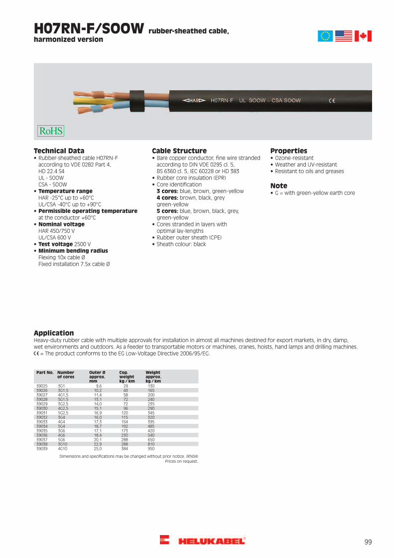
99
Technical Data
according to VDE 0282 Part 4, HD 22.4 S4 UL - SOOW CSA - SOOW
Temperature range HAR -25°C up to +60°C UL/CSA -40°C up to +90°C
Permissible operating temperature at the conductor +60°C
Nominal voltage HAR 450/750 V UL/CSA 600 V
Test voltage 2500 VMinimum bending radius
Flexing 10x cable Ø Fixed installation 7.5x cable Ø
Cable Structure
according to DIN VDE 0295 cl. 5, BS 6360 cl. 5, IEC 60228 or HD 383
3 cores: blue, brown, green-yellow 4 cores: brown, black, grey green-yellow 5 cores: blue, brown, black, grey, green-yellow
optimal lay-lengths
Properties
Note
H07RN-F/SOOW rubber-sheathed cable, harmonized version
ApplicationHeavy-duty rubber cable with multiple approvals for installation in almost all machines destined for export markets, in dry, damp, wet environments and outdoors. As a feeder to transportable motors or machines, cranes, hoists, hand lamps and drilling machines.
= The product conforms to the EG Low-Voltage Directive 2006/95/EG.
Dimensions and specifications may be changed without prior notice. (RN04) Prices on request.
Part No. Number of cores
Outer Ø approx. mm
Cop. weight kg / km
Weightapprox. kg / km
39025 3G1 9,6 29 13039026 3G1,5 10,2 43 16539027 4G1,5 11,4 58 20039028 5G1,5 13,1 72 24039029 3G2,5 14,0 72 23539030 4G2,5 15,1 96 29039031 5G2,5 16,9 120 34539032 3G4 16,0 115 32039033 4G4 17,3 154 39539034 5G4 18,7 192 48539035 3G6 17,1 173 42039036 4G6 18,4 230 54039037 5G6 20,1 288 65039038 3G10 22,9 288 81039039 4G10 25,0 384 950

100
HELUTHERM® 145 MULTI flexible, cross-linked, halogen-free, meter
marking
PropertiesCable structureTechnical dataTinned Cu wires, according to DIN VDE 0295class 5, BS 6360 cl. 5 and IEC 60228 class 5
Halogen-free control and connecting cablewith increased heat resistance
Reduced flame propagationGood abrasion and notch resistance
Temperature rangeflexing -35 °C to +120 °Cfixed installation -55 °C to +145 °Cin short-circuit +250 °C
Core insulation of polyolefin-copolymer,cross-linked and halogen-free
Good resistance to oils and weatheringResistant to UV radiation and ozone
Colour coded to DIN VDE 0293-308 and asof 6 cores number coded
Resistant to soldering temperaturesThermal class B
For two cores: brown, blueNominal voltageU0/U 300/500 V up to 1,0 mm²U0/U 450/750 V at 1,5 mm²with protected fixed installationU0/U 600/1000 V at 1,5 mm²
Are resistant to melting, even when incontact with a temperatures of between300 °C and 380 °C, because of thecross-linking for the insulation material
Green-yellow earth core as of 3 coresCores stranded in layers with optimallay-lengthTaping/Mica-Tape The materials used in manufacture are
cadmium-free and contain no silicone andTest voltage 3500 V Polyolefin-Copolymer, cross-linked andhalogen-free outer sheathMinimum bending radius
for fixed installation 4x cable øin operation to -30 °C 12x cable øin operation to +60 °C 8x cable ø
free from substances harmful to thewetting properties of lacquersColour black
with meter marking, change-over in 2011 TestsDifferent insulation- and outer sheath inother colours available on request.
Flame test (unit flame test) to VDE0482-332-3, BS 4066 part 3/ DIN EN60332-3-22, IEC 60332-3-22 (equivalent DINVDE 0472 part 804 test method C)
Caloric load valuessee Technical InformationsPower ratings tablesee Technical Informations Flame test (cable) to VDE 0482-332-1-2, DIN
EN 60332-1-2, IEC 60332-1-2 (equivalentDIN VDE 0472 part 804 test method B)
ApprovalGermanischer Lloyd
Corrosiveness of combustion gasesaccording to VDE 0482 part 267/ DIN EN50267-2-2/ IEC 60754-2 (equivalent DINVDE 0472 part 813)Halogen-free according to DIN VDE 0482part 267/ EN 50267-2-1/ IEC 60754-1(equivalent DIN VDE 0472 part 815)Smoke density to VDE 0482 part 268-1 and2, test method C, IEC 61034-1/61034-2,HD 606 and BS 7622 part 1 and 2(DIN VDE 0472 part 816)
NoteG = with green-yellow earth corex = without green-yellow earth corescreened analogue type:HELUTHERM® 145 MULTI-C
ApplicationThese halogen-free, cross-linked and temperature resistant wiring and control cables with enhanced fire-behaviour properties are used forwiring up the lighting fixtures, heaters, electric machines (temperature class B), switching systems and distribution switchboards. A verylong service life is also given on account of their excellent high-temperature stability.These cables exhibit good resistance to weathering as well as being very stable to temperature, moisture, ozone and UV radiation. Thesecables are therefore mainly used for traffic control systems and diverse outdoor applications. The development of smoke is low and nocorrosive gases are liberated during combustion of these halogen-free cables in case of fire. The risk of toxic fumes is considerably less inthe event of fire because the coloric load values is lower. Precious time can thus be won for a disciplined evacuation, and unnecessary lossof life can be prevented. The extent of the damage to costly control and monitoring systems and the concrete and steel structures ofbuildings and plant due to fire is reduced by this. Injuries to persons and damage to materials can be prevented. A lower conductorcross-section is possible in certain circumstances because of the high thermal load and thus savings in the space and weight required canbe made. These wiring and control cables provide a significant contribution in safety engineering and environmental protection.
= The product is conformed with the EC Low-Voltage Directive 2006/95/EG.
AWG-No.Weightapprox.kg / km
Cop.weightkg / km
Outer Øapprox. mm
No.cores xcross-sec.mm²
Part no. AWG-No.Weightapprox.kg / km
Cop.weightkg / km
Outer Øapprox. mm
No.cores xcross-sec.mm²
Part no.
2411,42,42,91 x 0,2553376 2441,89,65,54 G 0,25533792447,012,05,85 G 0,25533802428,74,84,62 x 0,2553377
2433,77,24,93 G 0,2553378 2458,014,46,56 G 0,2553381
Continuation Prices on request.

101
HELUTHERM® 145 MULTI flexible, cross-linked, halogen-free, meter
marking
AWG-No.Weightapprox.kg / km
Cop.weightkg / km
Outer Øapprox. mm
No.cores xcross-sec.mm²
Part no. AWG-No.Weightapprox.kg / km
Cop.weightkg / km
Outer Øapprox. mm
No.cores xcross-sec.mm²
Part no.
2464,016,86,97 G 0,2553382 16791,0345,621,124 G 1,55346516701,0360,021,125 G 1,5534662471,019,27,38 G 0,2553383
2484,024,08,110 G 0,2553384 16723,0388,821,127 G 1,55346716796,0432,021,830 G 1,5534682490,028,88,112 G 0,2553385
24102,033,68,614 G 0,2553386 16880,0475,222,633 G 1,553469161026,0532,824,837 G 1,55347024114,038,48,916 G 0,2553387
24132,045,610,119 G 0,2553388 1446,924,05,01 x 2,55347124145,050,410,521 G 0,2553389 1499,048,09,02 x 2,5534722015,74,83,21 x 0,553391 14140,072,09,83 G 2,553473
14183,096,010,84 G 2,5534742039,69,65,12 x 0,5533922048,114,45,53 G 0,553393 14231,0120,012,05 G 2,553475
14280,0144,013,26 G 2,5534762051,019,25,94 G 0,5533942064,024,06,75 G 0,553395 14336,0168,014,67 G 2,553477
14397,0192,015,78 G 2,5534782074,028,87,16 G 0,5533962088,033,67,87 G 0,553397 14460,0240,017,710 G 2,553479
14500,0288,018,712 G 2,55348020102,038,48,68 G 0,55339820123,048,09,410 G 0,553399 14593,0336,019,014 G 2,553481
14675,0384,020,116 G 2,55348220135,057,69,412 G 0,55340020153,067,210,014 G 0,553401 14835,0456,020,719 G 2,553483
14939,0504,023,721 G 2,55348420176,076,810,716 G 0,55340220213,091,212,419 G 0,553403 141047,0576,025,824 G 2,553485
141067,0600,025,825 G 2,55348620234,0100,813,021 G 0,55340420263,0115,214,024 G 0,553405 141107,0648,025,827 G 2,553487
141219,0720,026,730 G 2,55348820269,0120,014,025 G 0,55340620280,0129,614,027 G 0,553407 141349,0792,028,033 G 2,553489
141565,0888,030,637 G 2,55349020311,0144,015,030 G 0,55340820343,0158,415,033 G 0,553409 1296,038,45,61 x 45349120392,0177,617,037 G 0,553410 12159,076,810,22 x 4534921819,87,23,51 x 0,7553411 12197,0115,210,93 G 453493
12260,0153,612,24 G 4534941840,014,45,92 x 0,75534121853,021,66,23 G 0,7553413 12329,0192,013,55 G 453495
12398,0230,414,96 G 4534961869,028,86,94 G 0,75534141886,036,07,75 G 0,7553415 12478,0268,816,47 G 453497
12553,0307,217,68 G 45349818101,043,28,36 G 0,755341618117,050,49,17 G 0,7553417 12663,0384,020,110 G 453499
12725,0460,820,112 G 45350018140,057,610,28 G 0,755341818167,072,011,110 G 0,7553419 12797,0537,621,514 G 45350118183,086,411,112 G 0,7553420 1088,057,66,11 x 65350218212,0100,811,714 G 0,7553421 10216,0115,211,62 x 65350318239,0115,212,516 G 0,7553422 10285,0172,812,43 G 65350418290,0136,814,019 G 0,7553423 10375,0230,413,84 G 65350518323,0151,215,021 G 0,7553424 10465,0288,015,45 G 65350618364,0172,816,024 G 0,7553425 10544,0345,616,76 G 65350718371,0180,016,025 G 0,7553426 10664,0403,218,37 G 65350818387,0194,416,027 G 0,7553427 8144,096,07,71 x 105350918429,0216,017,030 G 0,7553428 8351,0192,014,72 x 105351018468,0237,618,033 G 0,7553429 8475,0288,015,73 G 105351118550,0266,419,037 G 0,7553430 8630,0384,017,54 G 10535121725,29,63,91 x 153431 8782,0480,019,65 G 10535131750,019,26,32 x 153432 8914,0576,021,76 G 10535141766,028,86,83 G 153433 81092,0672,023,77 G 10535151786,038,47,44 G 153434 6205,0153,69,11 x 165351617106,048,08,35 G 153435 6495,0307,217,72 x 165351717127,057,68,96 G 153436 6691,0460,819,33 G 165351817155,067,29,97 G 153437 6905,0614,421,54 G 165351917187,076,811,08 G 153438 61129,0768,023,95 G 165352017214,096,012,110 G 153439 61327,0921,626,26 G 165352117230,0115,212,112 G 153440 61590,01075,228,97 G 165352217266,0134,412,714 G 153441 4336,0240,010,91 x 255352317301,0153,613,616 G 153442 4833,0480,021,32 x 255352417377,0182,415,119 G 153443 41139,0720,022,73 G 255352517419,0201,616,021 G 153444 41489,0960,025,44 G 255352617464,0230,417,124 G 153445 41863,01200,028,15 G 255352717472,0240,017,125 G 153446 42275,01440,031,16 G 255352817488,0259,217,127 G 153447 42633,01680,034,57 G 255352917536,0288,017,730 G 153448 2454,0336,012,11 x 355353017605,0316,818,933 G 153449 21104,0672,023,72 x 355353117690,0355,220,337 G 153450 21513,01008,025,53 G 35535321632,314,44,31 x 1,553451 21992,01344,028,44 G 35535331669,028,87,62 x 1,553452 22488,01680,031,35 G 35535341693,043,28,13 G 1,553453 1638,0480,014,91 x 505353516120,057,68,84 G 1,553454 11573,0960,029,32 x 505353616152,072,09,85 G 1,553455 12154,01440,031,53 G 505353716187,086,410,96 G 1,553456 12819,01920,035,34 G 505353816222,0100,812,07 G 1,553457 13505,02400,039,15 G 505353916263,0115,214,08 G 1,553458 2/0875,0672,017,11 x 705354016308,0144,014,610 G 1,553459 2/02157,01344,033,72 x 705354116330,0172,814,612 G 1,553460 2/02946,02016,036,43 G 705354216383,0201,615,414 G 1,553461 2/03888,02688,040,34 G 705354316438,0230,416,216 G 1,553462 2/04864,03360,044,55 G 705354416554,0273,618,319 G 1,553463 3/01149,0912,019,21 x 955354516614,0302,419,721 G 1,553464 3/02763,01824,037,52 x 9553546
3/03835,02736,040,03 G 95535473/05052,03648,045,34 G 95535483/06307,04560,050,75 G 9553549
Dimensions and specifications may be changed without prior notice. (RE01) Prices on request.

102
PropertiesCable structureTechnical dataTinned copper conductor, fine wirestranded according to DIN VDE 0295 cl. 5,BS 6360 cl. 5 and IEC 60228 cl. 5
Halogen-free control and connecting cablewith increased heat resistance
Lower propagation of fireLow development of smoke and fumes
Temperature rangeflexing -35 °C to +120 °Cfixed installation -55 °C to +145 °Cin short-circuit +250 °C
Good abrasion and notch resistanceCore insulation of polyolefin-copolymer,cross-linked and halogen-free
Good resistance to oils and weatheringResistant to UV radiation and ozone
Black cores with continuous whitenumbering
Resistant to soldering temperaturesNominal voltageU0/U 300/500 V up to 1,0 mm²U0/U 450/750 V at 1,5 mm²with protected fixed installationU0/U 600/1000 V at 1,5 mm²
Thermal class BCores stranded in layers with optimallay-lenght
These control cables are resistant tomelting, even when in contact with asoldering iron at temperatures of between300 °C and 380 °C, because of thecross-linking for the insulation material
Braided screen of tinned Cu wires,coverage approx. 85Polyolefin-Copolymer, cross-linked andhalogen-free outer sheath
Test voltage 3500 VMinimum bending radiusfor fixed installation 4x cable øin operation to -30 °C 12x cable øin operation to +60 °C 8x cable ø
The materials used in manufacture arecadmium-free and contain no silicone andfree from substances harmful to thewetting properties of lacquers
Colour blackwith meter marking, change-over in 2011Different insulation- and outer sheath inother colours available on requestCoupling resistance
max. 250 Ohm/kmTests
Flame test (unit flame test) to VDE0482-332-3, BS 4066 part 3/ DIN EN60332-3-22, IEC 60332-3-22 (equivalent DINVDE 0472 part 804 test method C)
Caloric load valuessee Technical InformationsPower ratings tablesee Technical Informations
Flame test (cable) to VDE 0482-332-1-2, DINEN 60332-1-2, IEC 60332-1-2 (equivalentDIN VDE 0472 part 804 test method B)
ApprovalGermanischer Lloyd
Corrosiveness of combustion gasesaccording to VDE 0482 part 267/ DIN EN50267-2-2/ IEC 60754-2 (equivalent DIN VDE0472 part 813)
Halogen-free according to VDE 0482part 267/ DIN EN 50267-2-1/ IEC 60754-1(equivalent DIN VDE 0472 part 815)
Smoke density to VDE 0482 part 268-1 an2, test method C, IEC 61034-1/61034-2,HD 606 and BS 7622 part 1 and 2(DIN VDE 0472 part 816)
Noteunscreened analogue type:HELUTHERM® 145 MULTI
ApplicationThese halogen-free, cross-linked and temperature resistant wiring and control cables with enhanced fire-behaviour properties are used forwiring up the lighting fixtures, heaters, electric machines (temperature class B), switching systems and distribution switchboards. A verylong service life is also given on account of their excellent high-temperature stability.These cables exhibit good resistance to weathering as well as being very stable to temperature, moisture, ozone and UV radiation. Thesecables are therfore mainly used for traffic control systems and diverse outdoor applications. The development of smoke is low and nocorrosive gases are liberated during combustion of these halogen-free cables in case of fire. The risk of toxic fumes is considerably less inthe event of fire because the coloric load values is lower. Precious time can thus be won for a disciplined evacuation, and unnecessary lossof life can be prevented. The extent of the damage to costly control and monitoring systems and the concrete and steel structures ofbuildings and plant due to fire is reduced by this. Injuries to persons and damage to materials can be prevented. A lower conductorcross-section is possible in certain circumstances because of the high thermal load and thus savings in the space and weight required canbe made. These wiring and control cables provide a significant contribution in safety engineering and environmental protection.EMC = Electromagnetic compatibillity
= The product is conformed with the EC Low-Voltage Directive 2006/95/EG.
AWG-No.Weightapprox.kg / km
Cop.weightkg / km
Outer Øapprox. mm
No.cores xcross-sec.mm²
Part no. AWG-No.Weightapprox.kg / km
Cop.weightkg / km
Outer Øapprox. mm
No.cores xcross-sec.mm²
Part no.
2436,016,05,02 x 0,2552194 2444,021,05,53 x 0,2552195
Continuation
HELUTHERM® 145 MULTI-C flexible, cross-linked, halogen-free,
Cu-screened, EMC-preferred type, meter marking
Prices on request.

103
AWG-No.Weightapprox.kg / km
Cop.weightkg / km
Outer Øapprox. mm
No.cores xcross-sec.mm²
Part no. AWG-No.Weightapprox.kg / km
Cop.weightkg / km
Outer Øapprox. mm
No.cores xcross-sec.mm²
Part no.
2468,029,06,45 x 0,2552196 16105,058,08,22 x 1,55224116121,071,08,73 x 1,5522422495,037,07,57 x 0,255219716156,086,09,44 x 1,5522432024,015,03,71 x 0,55219816188,0104,010,55 x 1,5522442055,029,05,62 x 0,55219916225,0118,011,56 x 1,5522452064,038,06,13 x 0,55220016264,0136,012,67 x 1,5522462078,045,06,74 x 0,55220116308,0172,013,78 x 1,5522472095,051,07,35 x 0,55220216361,0193,015,010 x 1,55224820106,066,07,96 x 0,55220316383,0222,015,012 x 1,55224920122,068,08,47 x 0,55220416458,0272,016,014 x 1,55225020138,080,09,08 x 0,55220516515,0285,017,016 x 1,55225120161,093,010,010 x 0,55220616639,0331,019,319 x 1,55225220170,0107,010,012 x 0,55220716705,0367,020,321 x 1,55225320193,0122,011,014 x 0,5522081459,028,05,61 x 2,55225420216,0129,011,716 x 0,552209
20253,0158,012,819 x 0,552210 14148,096,09,82 x 2,55225514183,0146,010,43 x 2,55225620281,0167,013,521 x 0,55221114221,0150,011,54 x 2,5522571829,018,04,01 x 0,755221214273,0200,012,65 x 2,5522581871,038,06,62 x 0,755221314326,0227,013,86 x 2,5522591882,050,06,93 x 0,755221414397,0235,015,37 x 2,55226018100,058,07,64 x 0,755221514475,0265,016,58 x 2,55226118117,070,08,35 x 0,755221614542,0326,018,310 x 2,55226218135,085,08,96 x 0,755221714582,0376,018,312 x 2,55226318158,090,09,97 x 0,755221814681,0428,019,614 x 2,55226418178,0110,010,68 x 0,755221914778,0480,020,716 x 2,55226518207,0140,011,510 x 0,755222014948,0557,023,519 x 2,55226618220,0148,011,512 x 0,7552221141042,0606,024,421 x 2,55226718250,0167,012,214 x 0,75522221286,056,06,31 x 45226818282,0183,012,916 x 0,7552223
18335,0212,014,519 x 0,7552224 12196,0135,010,92 x 45226912248,0178,011,53 x 45227018370,0230,015,321 x 0,755222512316,0220,012,84 x 4522711733,020,04,21 x 15222612376,0259,014,35 x 4522721778,031,07,02 x 15222712452,0302,015,66 x 4522731792,056,07,43 x 15222812555,0355,017,07 x 45227417112,066,08,14 x 15222912655,0392,018,38 x 45227517134,095,08,95 x 15223012767,0480,020,710 x 45227617164,0105,09,56 x 15223112829,0557,020,712 x 45227717192,0109,010,57 x 15223212948,0636,022,114 x 45227817219,0130,011,48 x 15223310108,081,06,91 x 65227917254,0138,012,510 x 152234
17270,0164,012,512 x 152235 10255,0175,012,12 x 65228010330,0240,012,83 x 65228117308,0198,013,514 x 152236
17350,0203,014,316 x 152237 10429,0305,014,34 x 65228210536,0441,016,05 x 65228317447,0235,016,219 x 152238
17492,0257,017,021 x 152239 10624,0473,017,46 x 65228410751,0505,019,37 x 6522851642,022,04,81 x 1,5522408170,0124,08,41 x 10522868409,0265,015,12 x 10522878550,0370,016,43 x 10522888715,0485,018,14 x 10522898882,0610,020,25 x 105229081026,0715,022,36 x 105229181195,0820,024,37 x 1052292
Dimensions and specifications may be changed without prior notice. (RE01)
HELUTHERM® 145 MULTI-C flexible, cross-linked, halogen-free,
Cu-screened, EMC-preferred type, meter marking
Prices on request.

104
H07 V-K / (H)07 V-K PVC-Single Cores, fine wire stranded
PropertiesCable structureTechnical dataBare copper fine wire stranded toDIN VDE 0295 cl. 5, BS 6360 cl. 5, HD 383and IEC 60228 cl. 5
PVC single cores to DIN VDE 0281 part 3,HD 21.3 S3 and IEC 60227-3
PVC self-extinguishing and flame retardantaccording to VDE 0482-332-1-2, DIN EN60332-1-2/ IEC 60332-1 (equivalentDIN VDE 0472 part 804 test method B)
Temperature rangeflexing -5 °C to +70 °Cfixed installation -30 °C to +80 °C
PVC core insulation, compound TI1 toDIN VDE 0281 part 3, HD 21.3 S3 andIEC 60227-3
The materials used in manufacture arecadmium-free and contain no silicone andfree from substances harmful to thewetting properties of lacquers
Nominal voltage U0/U 450/750 VCore colours see belowTest voltage 2500 VCore Identification with nominalvoltage U0/U 450/750 V
Insulation resistancemin. 10 MOhm x km
NoteThe following colours are recommended(only single colour): black, white, blue, grey,
Minimum bending radius12,5 to 15x cable ø Colours yellow, green, transparent only in
(H)07 V-K available.brown, red, orange, turquoise, violet andpink. Two-coloured combinations are notallowed, with exceptions of green-yellow.
Radiation resistanceup to 80x106 cJ/kg (up to 80 Mrad) Two-coloured combination is only
permitted for (H)07 V-K.Colour code Single core cables H07see Technical Informations
ApplicationThese insulated wires are suitable for laying in tubes, under and surface mounting of plasters and also in closed installation conduits.These are not allowed to install for direct laying on cable trays, channels or tanks. These types are permitted for the inner wiring of equipment,distributor and switchboards and also for protective laying to the lightings with a nominal voltage up to 1000 V alternating current or up to750 V direct current against earth.
= The product is conformed with the EC Low-Voltage Directive 2006/95/EG.
Depending on the cross-section, this finely stranded single conductor is available in different colours and put-ups.
Put-ups: Ring in carton or foil, barrels, spools and reels. Colours: black-white, green-yellow, blue, brown, red, white, grey, violet, yellow, rose, green, trans, dark-blue, orange, ultramarine blue.
Put-ups:
Spool Barrel Coil in carton Coil in foil Reel 1,5 mm² to 6 mm² 1,5 mm² to 6 mm² 1,5 mm² to 6 mm² 1,5 mm² to 240 mm² 10 mm² to 240 mm²

105
H05Z-K / H07Z-K rubber insulated single core, halogen-free
PropertiesCable structureTechnical dataBare copper conductor, finewire strandedaccording to DIN VDE 0295 cl. 5, BS 6360cl. 5, IEC 60228, HD 383
Rubber-insulated single core cables for lowemission of smoke and corrosive gases incase of fire to VDE 0282 part 9 andHD 22.9 S2
The materials used in manufacture arecadmium-free and contain no silicone andfree from substances harmful to thewetting properties of lacquersCore identification according to
DIN VDE 0293 TestsConductor resistanceaccording to DIN VDE 0295 cl. 5 Separator over conductor permitted self-extinguishing and flame retardant
according to VDE 0482-332-1-2, DIN ENTemperature range-40 °C to +90 °C
Core insulation of cross-linked polyolefin,compound type EI5 to DIN VDE 0282 part 1 60332-1-2/ IEC 60332-1 (equivalent
DIN VDE 0472 part 804 test method B)Permissible working temperatureat the conductor +90 °C
Core colors see table below,dark blue and orange on request Ozone resistant according to EN 60811-2-1
/ HD 505.2.1Nominal voltageH05Z-K U0/U 300/500 VH07Z-K U0/U 450/750 V
LS0H = Low Smoke Zero Halogen-free.Smoke density according to VDE 0482part 1034-1+2, DIN EN 61034-1+2/IEC 61034-1+2, BS 7622 part 1+2 (equivalentDIN VDE 0472 part 816)
Test voltage 2500 VMinimum bending radiusapprox. 8x core ø
NoteRadiation resistanceup to 20x106 cJ/kg (up to 20 Mrad) AWG sizes are approximate equivalent
values. The actual cross-section is in mm².
ApplicationHalogen-free single-core wires are used for installation in dry environments for wiring up lighting fixtures and units where valuable assetsare to protected from further damage resulting from fire. These cables may be installed on, in and beneath plaster, as well as in closedinstallation ducts. The direct operating voltage is permitted up to 900 V against ground when they are used in rail-coaches. For the innerwiring of switch boards and distributors are to be used with an alternating nominal voltage up to 1000 V or a direct voltage up to 750 Vagainst ground.
= The product is conformed with the EC Low-Voltage Directive 2006/95/EG.
Depending on the cross-section, this finely stranded single conductor is available in different colours and put-ups.
Put-ups: Ring in carton or foil, barrels, spools and reels. Colours: black-white, green-yellow, brown, red, white, grey, violet, yellow, dark-blue, ultramarine blue
Put-ups:
Spool Barrel Coil in carton Coil in foil Reel 0,5 mm² to 6mm² 0,5 mm² to 6 mm² 0,5 mm² to 6 mm² 0,5 mm² to 240 mm² 10 mm² to 240 mm²

106
FIVENORM HAR-UL-CSA-AWM-MTW, PVC single core, UL-Style
10269/UL-Standard 1063, 600V, 105°C
PropertiesCable structureTechnical dataBare copper fine wire stranded toDIN VDE 0295 cl. 5, BS 6360 cl. 5, HD 383
PVC-single cores according to DIN VDE 0281part 7 and HD 21.7 S2, UL-Std. 1063,UL-Style 10269 and CSA-TEW andCSA-AWM I/A/B
PVC self-extinguishing and flame retardantaccording to VDE 0482-332-1-2, DIN EN60332-1-2/ IEC 60332-1 (equivalentDIN VDE 0472 part 804 test method B), ULVW-1, CSA FT1
and IEC 60228 cl. 5 and UL-Subject 758Section GPVC core insulation TI3 to DIN VDE 0281part 1 and UL-Std. 1581, class 43,CSA-C 22.2 No. 210 Tab. 12 class H
Temperature rangeH05 V2-K/H07 V2-Kflexing +5 °C to +90 °Cfixed installation -40 °C to +90 °CUL (AWM) -40 °C to +105 °CUL (MTW) -40 °C to +90 °CCSA (TEW) -40 °C to +105 °C
The materials used in manufacture arecadmium-free and contain no silicone andfree from substances harmful to thewetting properties of lacquers
Core colours to DIN VDE 02932-colour combination - Part No. on request
NoteNominal voltageH05 V2-K: U0/U 300/500 V (up to 1 mm²)H07 V2-K: U0/U 450/750 V (1,5 mm²)UL (AWM) U 1000 VUL (MTW) U 600 VCSA (TEW) U 600 VTest voltageH05 V2-K/H07 V2-K 2000 V
Tinned conductor on request.The cross-sections 0,5 mm², 0,75 mm² and1,0 mm² are according to H05 V2-K, thecross-sections 1,5 up to 35 mm² accordingto H07 V2-K, the cross-sections 35 mm²are identified as H07 V-K.Cross-sections up to 35 mm² is accordingto DIN VDE 0281 part 7. Due to this
Spark TestAWG 20: 5 kV
AWG 20: 6 kV
cross-section 35 mm² is the type but withan increased heat-resistantPVC-compound.
Insulation resistancemin. 20 MOhm x km
Type H05 V:approved one-colour mark: black, blue,brown, grey, orange, pink, red, turquoise,violet, white, green and yellow.Two-coloured mark in any combination ofthe above individual colours.
Minimum bending radiusfor permanent bendingca. 10-15 core ø
Type H07 V:approved mark: black, blue, brown, grey,orange, pink, red, turquoise, violet, whiteand green-yellow.Other marks are available as (H).
ApplicationFive norms approved connecting jumper wire primarily designed for exportes, used in machine tools. The approbation of HAR, UL-AWM,UL-MTW, CSA-AWM, CSA-Equipment-wire make possible an economical storekeeping and simplification of parts list.
= The product is conformed with the EC Low-Voltage Directive 2006/95/EG.
Cross-sec.mm² / AWG-no.
Outer Øapp. mm
Cop. weightkg / km
approx. RALblack9005
blue5015
brown8003
red3000
white1013
grey7000
vio4005
pink3015
og2003
green6018
ye1021
gn-ye-
2-col-
dk-bu5010
trans-
o.col.-
Part no. 0,5 / 20 2,5 5,2 64075 64077 64078 64079 64080 64081 64082 64084 64088 64085 64083 64076 64090 64087 64086 64089Part no. 0,75 / 19 2,65 7,2 64091 64093 64094 64095 64096 64097 64098 64100 64104 64101 64099 64092 64106 64103 64102 64105Part no. 1 / 18 2,8 9,6 64107 64109 64110 64111 64112 64113 64114 64116 64120 64117 64115 64108 64122 64119 64118 64121Part no. 1,5 / 16 3,05 14,4 64123 64125 64126 64127 64128 64129 64130 64132 64136 64133 64131 64124 64138 64135 64134 64137Part no. 2,5 / 14 3,6 24,0 64139 64141 64142 64143 64144 64145 64146 64148 64152 64149 64147 64140 64154 64151 64150 64153Part no. 4 / 12 4,1 38,0 64155 64157 64158 64159 64160 64161 64162 64164 64168 64165 64163 64156 64170 64167 64166 64169Part no. 6 / 10 4,8 58,0 64171 64173 64174 64175 64176 64177 64178 64180 64184 64181 64179 64172 64186 64183 64182 64185Part no. 10 / 8 6,4 96,0 64187 64189 64190 64191 64192 64193 64194 64196 64200 64197 64195 64188 64202 64199 64198 64201Part no. 16 / 6 8,1 154,0 64203 64205 64206 64207 64208 64209 64210 64212 64216 64213 64211 64204 64218 64215 64214 64217Part no. 25 / 4 9,6 240,0 64219 64221 64222 64223 64224 64225 64226 64228 64232 64229 64227 64220 64234 64231 64230 64233Part no. 35 / 2 10,8 336,0 64235 64237 64238 64239 64240 64241 64242 64244 64248 64245 64243 64236 64250 64247 64246 64249Part no. 50 / 1 13,6 480,0 64251 64253 64254 64255 64256 64257 64258 64260 64264 64261 64259 64252 64266 64263 64262 64265Part no. 70 / 2/0 15,2 672,0 64267 64269 64270 64271 64272 64273 64274 64276 64280 64277 64275 64268 64282 64279 64278 64281Part no. 95 / 3/0 16,8 912,0 64283 64285 64286 64287 64288 64289 64290 64292 64296 64293 64291 64284 64298 64295 64294 64297Part no. 120 / 4/0 19,5 1152,0 64299 64301 64302 64303 64304 64305 64306 64308 64312 64309 64307 64300 64314 64311 64310 64313Part no. 150 / 300 kcmil 22,2 1440,0 64315 64317 64318 64319 64320 64321 64322 64324 64328 64325 64323 64316 64330 64327 64326 64329
Dimensions and specifications may be changed without prior notice.Prices on request.

107
HELUTHERM® 145 flexible, cross-linked, halogen-free
PropertiesCable structureTechnical dataTinned Cu wires, according to DIN VDE 0295cl. 5, BS 6360 cl. 5 and IEC 60228 cl. 5
Halogen-free single cores with increasedheat resistance
Lower propagation of fireLow development of smoke and fumes
Temperature rangeflexing -35 °C to +120 °Cfixed installation -55 °C to +145 °C
Core insulation of polyolefin-copolymer,cross-linked
Good abrasion and notch resistanceGood resistance to oils and weathering
Core colours see table Resistant to UV radiation and ozoneTestsNominal voltage
U0/U 300/500 V up to 1 mm²U0/U 450/ 750 V from 1,5 mm²for fixed and protected installationU0/U 600/1000 V from 1,5 mm²
Resistant to soldering temperaturesFlame test (unit flame test) to VDE0482-332-3, BS 4066 part 3/ DIN EN60332-3-22, IEC 60332-3-22 (equivalent DINVDE 0472 part 804 test method C)
Thermal class BThese single-core cables are resistant tomelting, even when in contact with asoldering iron at temperatures of between
Test voltage 3500 V Flame test (cable) to VDE 0482-332-1-2,DIN EN 60332-1-2, IEC 60332-1-2
300 °C and 380 °C, because of thecross-linking for the insulation materialMinimum bending radius
flexing 12,5x cable øfixed installation 4x cable ø
(equivalent DIN VDE 0472 part 804 testmethod B)
Due to the high temperature profile thecross-section of conductor can under
Corrosiveness of combustion gasesaccording to VDE 0482 part 267/
Caloric load valuessee Technical Informations
certain circumstances be reduced, herebyenabling a saving in space requirement andweightDIN EN 50267-2-2/ IEC 60754-2 (equivalent
DIN VDE 0472 part 813)Power ratings tablesee Technical Informations The materials used in manufacture are
cadmium-free and contain no silicone andHalogen-free according to VDE 0482part 267/ DIN EN 50267-2-1/ IEC 60754-1(equivalent DIN VDE 0472 part 815)
ApprovalGermanischer Lloyd free from substances harmful to the
wetting properties of lacquersSmoke density to VDE 0482 part 268-1and 2, test method C, IEC 61034-1/61034-2,HD 606 and BS 7622 part 1 and 2(DIN VDE 0472 part 816)
ApplicationThese temperature resistant single-core cables are used for the internal wiring of lighting fixtures, heaters, electrical machinery, switchingsystems and distributors in equipment and plant and machinery, suitable for installation on, in and beneath plaster, in closed installationducts, as well as for traffic systems and outdoor applications. These cables are not approved for direct routing on racks, gutters or tanks.For a protected installation, these cables may be used at a nominal voltage of up to 1000 V alternating current or a direct current up to 750V when earthed. The maximum operating d.c. voltage used in rail vehicles shall not exceed 900 V when earthed. These halogen-free singlecore cables are characterised by their amazingly high long-time resistance to temperature and feature among the leading halogen-free,flame resistant products in the world. These single core cables significantly contribute to safety and the environment.
= The product is conformed with the EC Low-Voltage Directive 2006/95/EG.
Cross-section mm²
Outer Ømin - maxmm
Cop.weightkg / km
Weightapprox. kg / km
approx. RAL black gn-ye brown red white grey vio dk-bu yellow Beige lt-bu og green 2-col.
Part no. 0,25 1,4 - 1,8 2,4 4 50999 50998 51071 51072 51073 51074 51075 51079 51076 51164 51070 51077 51078 51165Part no. 0,33 1,5 - 1,9 3,2 5 51167 51166 51169 51170 51171 51172 51173 51177 51174 51178 51168 51175 51176 51179Part no. 0,5 1,7 - 2,1 4,8 7 51281 51280 51283 51284 51285 51286 51287 51291 51288 51292 51282 51289 51290 51293Part no. 0,75 2,0 - 2,4 7,2 11 51295 51294 51297 51298 51299 51300 51301 51305 51302 51306 51296 51303 51304 51307Part no. 1 2,3 - 2,7 9,6 14 51309 51308 51311 51312 51313 51314 51315 51319 51316 51320 51310 51317 51318 51321Part no. 1,5 2,7 - 3,1 14,4 20 51323 51322 51325 51326 51327 51328 51329 51333 51330 51334 51324 51331 51332 51335Part no. 2,5 3,3 - 3,7 24 30 51337 51336 51339 51340 51341 51342 51343 51347 51344 51348 51338 51345 51346 51349Part no. 4 4,1 - 4,5 38 47 51351 51350 51353 51354 51355 51356 51357 51361 51358 51362 51352 51359 51360 51363Part no. 6 4,8 - 5,2 58 72 51365 51364 51367 51368 51369 51370 51371 51375 51372 51376 51366 51373 51374 51377Part no. 10 6,5 - 6,6 96 120 51379 51378 51381 51382 51383 51384 51385 51389 51386 51390 51380 51387 51388 51391Part no. 16 7,2 - 7,8 154 182 51420 51419 51422 51423 51424 51425 51426 51430 51427 51431 51421 51428 51429 51432Part no. 25 9,4 - 9,8 240 272 51434 51433 51436 51437 51438 51439 51440 51444 51441 51445 51435 51442 51443 51446Part no. 35 10,3 - 11,1 336 371 51448 51447 51450 51451 51452 51453 51454 51458 51455 51459 51449 51456 51457 51460Part no. 50 12,6 - 13,4 480 530 51462 51461 51464 51465 51466 51467 51468 51472 51469 51473 51463 51470 51471 51474Part no. 70 14,7 - 15,4 672 730 51476 51475 51478 51479 51480 51481 51482 51486 51483 51487 51477 51484 51485 51488Part no. 95 16,9 - 17,7 912 964 51490 51489 51492 51493 51494 51495 51496 51500 51497 51501 51491 51498 51499 51502Part no. 120 18,6 - 19,8 1152 1235 51504 51503 51506 51507 51508 51509 51510 51514 51511 51515 51505 51512 51513 51516Part no. 150 20,8 - 22,0 1440 1523 51518 51517 51520 51521 51522 51523 51524 51528 51525 51529 51519 51526 51527 51530Part no. 185 23,0 - 24,2 1776 1850 51532 51531 51534 51535 51536 51537 51538 51542 51539 51543 51533 51540 51541 51544Part no. 240 26,1 - 27,3 2304 2432 51546 51545 51548 51549 51550 51551 51552 51556 51553 51557 51547 51554 51555 51558
Dimensions and specifications may be changed without prior notice. (RK01)Prices on request.

108
Cross-section mm²
Outer Øapprox. mm
Cop.weightkg / km
Weightapprox.kg / km
approx. RAL
black
9005
brown
8003
red
3000
white
1013
grey
7000
vio
4005
green
6018
Beige
1001
pink
3015
lt-blue
5015
og
2003
ye
1021
gn-ye
6018
2-col.
-Part no. 0,25 2,3 2,4 7,0 59473 59475 59476 59477 59478 59479 59482 59484 59483 59474 59481 59480 59472 59485Part no. 0,5 2,6 4,8 11,0 59487 59489 59490 59491 59492 59493 59496 59498 59497 59488 59495 59494 59486 59499Part no. 0,75 2,8 7,2 14,0 59501 59503 59504 59505 59506 59507 59510 59512 59511 59502 59509 59508 59500 59513Part no. 1 2,9 9,6 17,0 59515 59517 59518 59519 59520 59521 59524 59526 59525 59516 59523 59522 59514 59527Part no. 1,5 3,2 14,4 22,0 59529 59531 59532 59533 59534 59535 59538 59540 59539 59530 59537 59536 59528 59541Part no. 2,5 3,7 24,0 33,0 59543 59545 59546 59547 59548 59549 59552 59554 59553 59544 59551 59550 59542 59555Part no. 4,0 4,2 38,4 53,0 59557 59559 59560 59561 59562 59563 59566 59568 59567 59558 59565 59564 59556 59569Part no. 6,0 4,8 57,6 78,0 59571 59573 59574 59575 59576 59577 59580 59582 59581 59572 59579 59578 59570 59583Part no. 10,0 6,7 96,0 136,0 59585 59587 59588 59589 59590 59591 59594 59596 59595 59586 59593 59592 59584 59597Part no. 16,0 8,5 154,0 203,0 59599 59601 59602 59603 59604 59605 59608 59610 59609 59600 59607 59606 59598 59611Part no. 25,0 10,4 240,0 300,0 59613 59615 59616 59617 59618 59619 59622 59624 59623 59614 59621 59620 59612 59625Part no. 35,0 11,5 336,0 405,0 59627 59629 59630 59631 59632 59633 59636 59638 59637 59628 59635 59634 59626 59639Part no. 50,0 14,4 480,0 580,0 59641 59643 59644 59645 59646 59647 59650 59652 59651 59642 59649 59648 59640 59653
Dimensions and specifications may be changed without prior notice.Prices on request.
HELUTHERM® 145600V, flexible single core, cross-linked, halogen-free
PropertiesCable structureTechnical dataTinned Cu wires, according to DIN VDE 0295cl. 5, BS 6360 cl. 5 and IEC 60228 cl. 5
Halogen-free single cores with increasedheat resistance according toUL Style 3271CSA CL 1251
Halogen-freeLower propagation of fire
Core insulation of polyolefin-copolymer,cross-linked, flame retardant, halogen-free
Low development of smoke and fumesGood abrasion and notch resistance
Core colours see table belowTemperature rangeflexing -35 °C to +120 °Cfixed installation -55 °C to +125 °Cin short circuit +280 °C
Good resistance to oils and weatheringTestsFlame test to VDE 0482 Teil 266-2,BS 4066 part 3/ DIN EN 50266-2/
Resistant to UV radiation and ozoneResistant to soldering temperaturesResistant to melting, even when in contactwith a soldering iron at temperatures ofNominal voltage U 600 V IEC 60332-3 (equivalent DIN VDE 0472
part 804 test method C)Corrosiveness of combustion gasesaccording to VDE 0482 part 267/
Test voltage 3500 V between 300 °C and 380 °C, because of thecross-linking for the insulation materialMinimum bending radius
flexing approx. 12,5x core øfixed installation approx. 4x core ø
Due to the high temperature profile thecross-section of conductor can underDIN EN 50267-2-2/ IEC 60754-2 (equivalent
DIN VDE 0472 part 813)Halogen-free accordingto VDE 0482part 267/ DIN EN 50267-2-1/ IEC 60754-1(equivalent DIN VDE 0472 part 815)Smoke density to VDE 0482 part1034-1+2/ IEC 61034-1+2 / DIN EN
Caloric load valuessee Technical Informations
certain circumstances be reduced, herebyenabling a saving in space requirement andweightPower ratings table
see Technical Informations The materials in manufacture arecadmium-free +contain no silicone +freefrom substances harmful to the wettingproperties of lacquers61034-1+2 / BS 7622 part 1+2 (equivalent
DIN VDE 0472 part 816)
ApplicationThese temperature resistant single-core cables are used for the internal wiring of lighting fixtures, heaters, electrical machinery, switchingsystems and distributors in equipment and plant and machinery, suitable for installation on, in and beneath plaster, in closed installationducts, as well as for traffic systems and outdoor applications. These cables are not approved for direct routing on racks, gutters or tanks.For a protected installation, these cables may be used at a nominal voltage of up to 1000 V alternating current or a direct current up to750 V when earthed. The maximum operating d.c. voltage used in rail vehicles shall not exceed 900 V when earthed.
= The product is conformed with the EC Low-Voltage Directive 2006/95/EG.

109
THHN/THWN 90°C, 600V, UL listed, PVC + nylon single core
PropertiesCable structureTechnical dataBare copper conductor, AWG-sizes as pergiven table below and ASTM B-3 and ASTMB-8
PVC + Nylon insulated single cores as perUL-Styles und NEC standard
Resistant againstOilsGasolineWaterAcidsOzoneLyesSunlightAbrasion
Temperature range as per StylesTHHN: 90 °C dry - NEC standardTHWN: 75 °C wet - NEC standardAWM: UL-Styles 1316 to 1321105 °C dry80 °C in oilAWM: UL-Styles 1452, 145390 °C dry80 °C in oil 1000 VMTW: UL-Styles 1408 to 141490 °C dry80 °C in oil 600 V
Core insulation of PVC+Nylon-outer-sheathCores colour coded, colour identificationsee belowSurface of jacket printed with markings:14 to 1000 MCM THHN (stranded) - (size)AWG Type MTW OR THHN OR THWN 600 VOR GASOLINE AND OIL RESTSTANT II (UL) ORAWM W-5155414 to 10 AWG THHN (solid) - (size)AWG TYPE THHN OR THWN 600 V ORGASOLINE AND OIL RESISTANT II (UL) OR AWM
Note1 kcmil = 1000 circ mils = 0,5067 mm².Please complete the above part numberfor the colour required, using the followingcode:0 = green1 = black2 = blue3 = brown4 = red5 = white6 = grey7 = yellow8 = orange9 = pink
Nominal voltage 600 VMinimum bending radius8x core øTest voltage (Spark test)AWG 14 to AWG 10 = 7,5 kVAWG 8 to AWG 2/0 = 10 kVAWG 3/0 to AWG 4/0 = 12,5 kVkcmil 250 to kcmil 500 = 15 kVkcmil 600 to kcmil 1000 = 17,5 kV
ApplicationAs flexible connecting cable in machines, switch and distribution cabinets, cable assemblies and for fixed indoor installation, in tubes and incable conduits.AWM = Appliance Wiring Material / For internal wrings for electrical equipment and control apparatus e.g. radio and televisions, electronicassembly component.MTW = Machine Tool Wire / For the electronical installation of machine tools and the relative control.THW = Thermoplastic PVC-insulated building wire, Heat resistant 75 °C, for Wet and dry locations, flame retardant.THHN = Thermoplastic PVC-insulated building wire, Nylon jacketed, 90 °C 600 V, for dry and damp locations.
= The product is conformed with the EC Low-Voltage Directive 2006/95/EG.
Weightapprox. kg / km
Cop.weightkg / km
Outer Øapprox. mm
Cond. make-upn x wire Ø
AWGsize
AWG-No.Cross-sec. mm²Part no.
25,020,73,019 x 0,380,0147142,086320x37,033,03,419 x 0,480,0185123,326321x60,051,64,319 x 0,60,0234105,266322x95,080,65,519 x 0,750,029588,356323x
143,0125,06,619 x 0,960,0378613,396324x229,0201,08,419 x 1,190,0469421,146325x282,0253,09,119 x 1,3360,053326,656326x349,0317,010,019 x 1,50,0591233,616327x449,0399,011,419 x 1,6860,0664142,386328x557,0500,012,419 x 1,890,07451/053,476329x691,0631,013,719 x 2,1260,08372/067,46330x861,0792,015,019 x 2,3870,0943/084,976331x
1069,0996,016,519 x 2,680,10554/0107,176332x
Weightapprox. kg / km
Cop.weightkg / km
Outer Øapprox. mm
Cond. make-upn x wire Ø
AWGsize
AWG-No.Cross-sec. mm²Part no.
1277,01178,018,2937 x 2,0880,0822250 kcmil127633311515,01410,019,5637 x 2,2860,09300 kcmil152633411753,01645,021,0837 x 2,470,0973350 kcmil178633511998,01902,022,3537 x 2,70,104400 kcmil203633612466,02345,024,1337 x 2,950,1162500 kcmil254633713000,02920,026,7561 x 2,520,0992600 kcmil304633813713,03658,029,3661 x 2,820,1109750 kcmil380633914796,04858,033,2761 x 3,250,1281000 kcmil50763401
Dimensions and specifications may be changed without prior notice. (RN06) Prices on request.

110
PAAR-TRONIC-CY flexible, Cu-screened, colour coded to DIN 47100,
EMC-preferred type, meter marking
PropertiesCable structureTechnical dataBare copper, fine wire conductors, bunchstranded to DIN VDE 0295 cl. 5, 0245 andIEC 60228 cl. 5
Special PVC data cables, adapted toDIN VDE 0812, 0814
Extensively oil resistant, oil-/ chemicalResistance - see table TechnicalInformationsTemperature range
flexing -5 °C to +80 °Cfixed installation -30 °C to +80 °C
PVC self-extinguishing and flame retardantaccording to VDE 0482-332-1-2, DIN EN60332-1-2/ IEC 60332-1 (equivalentDIN VDE 0472 part 804 test method B)
Conductor make-up for0,14 mm² = 18x0,1 mm0,25 mm² = 14x0,15 mm0,34 mm² = 7x0,25 mm
Operating voltage 350 V(not for purposes of high current andpower installation) Special PVC core insulation YI2, to
DIN VDE 0207 part 4The materials used in manufacture arecadmium-free and contain no silicone andfree from substances harmful to thewetting properties of lacquers
Test voltagecore/core 1200 Vcore/screen 800 V
Colours coded to DIN 47100 with colourrepetitionCores stranded in pairs with optimallay-length
Breakdown voltage min. 2400 V
NoteInsulation resistancemin. 20 MOhm x km Pairs stranded in layers with optimal
lay-lengthAlso available in other sheath colours.
Conductor resistanceat 0,14 mm² 138 Ohm/kmat 0,25 mm² 75,5 Ohm/kmat 0,34 mm² 57,5 Ohm/kmat 0,50 mm² 39 Ohm/kmat 0,75 mm² 26 Ohm/km
unscreened analogue type:Core wrapping with foilTinned copper braided screening, coverageapprox. 85Special PVC outer sheath YM2, toDIN VDE 0207 part 5Sheath colour grey (RAL 7032)Capacitance (approx.-value) at 800 Hz
core/core 0,14 mm² = 120 pF/mcore/core 0,25 mm² = 150 pF/mcore/screen 0,14 mm² = 240 pF/mcore/screen 0,25 mm² = 270 pF/m
with meter marking, change-over in 2011
Loadat 0,14 mm² = 1,5 Aat 0,25 mm² = 2,5 Aat 0,34 mm² = 4,5 Aat 0,50 mm² = 6 Aat 0,75 mm² = 9 AInductance approx. 0,65 mH/kmImpedance approx. 78 OhmK1-coupling approx. 300 pF/100 mCoupling resistancemax.250 Ohm/kmMinimum bending radiusflexing 10x cable øfixed installation 5x cable øRadiation resistanceup to 80x106 cJ/kg (up to 80 Mrad)
ApplicationThese data control cables are used for flexible use with free movement without tensile stress or forced movements in dry, moist and wetrooms but not suitable for open air.PAAR-TRONIC-CY is well suited for use in areas subject to signal interference. The high level of screening reduces substantially the effectsof electrical disturbances from parallel running wiring etc. The copper screening is also often used as an "earth".The twisted pairs conform favourable cross-talk attenuation values. These cables are suitable for dry and wet rooms, yet not for open air.EMC = Electromagnetic compatibillity
= The product is conformed with the EC Low-Voltage Directive 2006/95/EG.
AWG-No.Weightapprox.kg / km
Cop.weightkg / km
Outer Øapprox. mm
No.pairs xcross-sec.mm²
Part no. AWG-No.Weightapprox.kg / km
Cop.weightkg / km
Outer Øapprox. mm
No.pairs xcross-sec.mm²
Part no.
2634,015,64,11 x 2 x 0,1421001 2686,048,57,26 x 2 x 0,14210062691,051,17,27 x 2 x 0,14210072640,018,55,62 x 2 x 0,1421002
2649,023,05,63 x 2 x 0,1421003 2697,053,78,48 x 2 x 0,142100826109,059,09,110 x 2 x 0,14210092655,026,66,04 x 2 x 0,1421004
2666,030,76,75 x 2 x 0,1421005 26141,066,09,212 x 2 x 0,1421010
Continuation
PAAR-TRONIC
Prices on request.

111
PAAR-TRONIC-CY flexible, Cu-screened, colour coded to DIN 47100,
EMC-preferred type, meter marking
AWG-No.Weightapprox.kg / km
Cop.weightkg / km
Outer Øapprox. mm
No.pairs xcross-sec.mm²
Part no. AWG-No.Weightapprox.kg / km
Cop.weightkg / km
Outer Øapprox. mm
No.pairs xcross-sec.mm²
Part no.
26148,074,09,914 x 2 x 0,1421011 2278,044,97,33 x 2 x 0,34199722290,054,28,14 x 2 x 0,341997326152,076,010,415 x 2 x 0,1421012
26155,079,010,416 x 2 x 0,1421013 22110,063,58,85 x 2 x 0,341997422130,073,19,86 x 2 x 0,341997526171,083,011,018 x 2 x 0,1421014
26183,097,011,520 x 2 x 0,1421015 22145,079,59,87 x 2 x 0,341997622150,088,411,28 x 2 x 0,341997726205,0103,012,322 x 2 x 0,1421016
26228,0111,012,324 x 2 x 0,1421017 22170,099,312,69 x 2 x 0,341997822190,0106,912,610 x 2 x 0,341997926239,0113,012,525 x 2 x 0,1421018
26245,0122,012,526 x 2 x 0,1421019 22220,0122,112,812 x 2 x 0,341998022245,0138,213,314 x 2 x 0,341998126251,0125,012,527 x 2 x 0,1421020
26258,0128,013,728 x 2 x 0,1421021 22250,0154,214,316 x 2 x 0,341998222275,0197,915,218 x 2 x 0,341998326270,0140,013,730 x 2 x 0,1421022
26284,0145,014,232 x 2 x 0,1421023 22300,0214,415,921 x 2 x 0,341998422400,0238,517,525 x 2 x 0,341998526300,0150,014,734 x 2 x 0,1421024
26316,0156,014,936 x 2 x 0,1421025 22410,0262,517,527 x 2 x 0,341998622440,0286,619,130 x 2 x 0,341998726350,0162,015,638 x 2 x 0,1421026
26370,0177,016,140 x 2 x 0,1421027 22510,0310,120,834 x 2 x 0,341998822550,0368,721,537 x 2 x 0,341998926390,0181,016,844 x 2 x 0,1421028
26430,0195,017,046 x 2 x 0,1421029 22590,0392,622,440 x 2 x 0,341999022600,0424,323,644 x 2 x 0,341999126440,0202,017,750 x 2 x 0,1421030
26460,0206,017,752 x 2 x 0,1421031 22650,0455,924,850 x 2 x 0,341999222680,0487,624,852 x 2 x 0,341999326480,0210,018,255 x 2 x 0,142103222750,0518,525,456 x 2 x 0,34199942445,015,04,61 x 2 x 0,252103322840,0557,226,261 x 2 x 0,34199952453,028,06,32 x 2 x 0,25210342060,024,05,61 x 2 x 0,5170472465,032,06,63 x 2 x 0,2521035
2480,038,07,04 x 2 x 0,2521036 2089,054,07,82 x 2 x 0,51700120104,070,08,23 x 2 x 0,5170022498,055,07,85 x 2 x 0,2521037
24114,065,08,66 x 2 x 0,2521038 20126,091,09,14 x 2 x 0,51700320148,0105,09,95 x 2 x 0,51700424121,070,08,67 x 2 x 0,2521039
24129,075,09,88 x 2 x 0,2521040 20171,0120,010,76 x 2 x 0,51700520290,0144,012,88 x 2 x 0,51700624157,0110,011,010 x 2 x 0,2521041
24189,0117,011,212 x 2 x 0,2521042 20320,0178,014,010 x 2 x 0,51700720361,0199,014,312 x 2 x 0,51700824213,0122,012,214 x 2 x 0,2521043
24225,0134,012,815 x 2 x 0,2521044 20421,0254,016,116 x 2 x 0,51700920580,0302,017,220 x 2 x 0,51701024237,0143,012,816 x 2 x 0,2521045
24248,0148,013,518 x 2 x 0,2521046 20740,0344,019,725 x 2 x 0,51701124275,0162,014,120 x 2 x 0,2521047 1971,028,06,01 x 2 x 0,751704824303,0172,014,922 x 2 x 0,2521048 19105,058,08,42 x 2 x 0,751701224330,0223,015,324 x 2 x 0,2521049 19128,084,08,93 x 2 x 0,751701324343,0233,015,525 x 2 x 0,2521050 19156,0108,09,84 x 2 x 0,751701424345,0238,015,526 x 2 x 0,2521051 19189,0126,010,85 x 2 x 0,751701524350,0244,015,527 x 2 x 0,2521052 19216,0146,012,16 x 2 x 0,751701624360,0249,017,028 x 2 x 0,2521053 19309,0180,013,48 x 2 x 0,751701724375,0254,017,030 x 2 x 0,2521054 19355,0220,015,510 x 2 x 0,751701824400,0290,017,632 x 2 x 0,2521055 19405,0261,015,812 x 2 x 0,751701924410,0312,018,234 x 2 x 0,2521056 19565,0328,018,016 x 2 x 0,751702024420,0322,018,236 x 2 x 0,2521057 19700,0392,019,220 x 2 x 0,751702124450,0339,019,038 x 2 x 0,2521058 19950,0470,021,825 x 2 x 0,751702224485,0349,019,740 x 2 x 0,2521059 1875,046,06,31 x 2 x 11704924500,0359,020,544 x 2 x 0,2521060 18116,082,08,92 x 2 x 11705024540,0398,020,746 x 2 x 0,2521061 18140,0103,09,43 x 2 x 11705124550,0403,021,550 x 2 x 0,2521062 18191,0132,010,44 x 2 x 11705224580,0435,021,552 x 2 x 0,2521063 1684,063,07,21 x 2 x 1,51705324630,0464,022,155 x 2 x 0,2521064 16122,0111,010,22 x 2 x 1,5170542258,016,05,21 x 2 x 0,3419970 16194,0136,010,83 x 2 x 1,5170552265,036,97,02 x 2 x 0,3419971 16240,0172,012,04 x 2 x 1,517056
Dimensions and specifications may be changed without prior notice. (RB01) Prices on request.

112
DATAFLAMM halogen-free, meter marking
PropertiesCable structureTechnical dataBare copper, fine wire conductors toDIN VDE 0812, conductor make-up for0,34 mm² - 7x0,25 mm
Special data cable Halogen-free according to VDE 0482part 267/ DIN EN 50267-2-1/ IEC 60754-1(equivalent DIN VDE 0472 part 815)
Temperature rangeflexing +5 °C to +70 °Cfixed installation -40 °C to +70 °C Corrosiveness of combustion gases
according to VDE 0482 part 267/PE-insulation, compound type 2YJ1 toDIN VDE 0207 part 2Nominal voltage
0,14 mm² = 350 V0,14 mm² = 500 V
DIN EN 50267-2-2/ IEC 60754-2 (equivalentDIN VDE 0472 part 813)
Cores colour coded to DIN 47100Cores twisted in layers with optimallay-length Halogen-free sheath compound,
self-extinguishing and flame retardantTest voltage0,14 mm² = 800 V
0,14 mm² = 1200 VHalogen-free outer sheath, toDIN VDE 0207 part 24, compound type HM2 according to DIN VDE 0482 part 265-2-1/
EN 50265-2-1/ IEC 60332-1 (equivalentDIN VDE 0472 part 804 test method B)
Sheath colour grey, RAL 7005Insulation resistancemin. 2 GOhm x km with meter marking, change-over in 2011Capacitancecore/core 70 nF/km NoteMinimum bending radiusapprox. 7,5x cable ø
screened analogue type:
Radiation resistanceup to 100x106 cJ/kg (up to 100 Mrad)
ApplicationDATAFLAMM halogen-free data cables are used as connecting cable for signal, measuring, control, call-announcing and two-way intercomspeaking systems, clock installations, electronic weighing equipment and electrical apparatus for office requirements. The cables are suitablefor installation in dry, damp and wet environments as well as in masonry and concrete.PE-insulated-cores, compared with the conventional PVC-insulated cores, assure a remarkable and more favourable capacitance values.These cables are generally installed in telecommunication apparatus and data transmission systems in public buildings, laboratories, tradingcentres where the freedom from halogen in case of fire and the flame propagation must be avoided.The halogen-free thermoplastic sheath produce neither corrosive nor toxic gases.
= The product is conformed with the EC Low-Voltage Directive 2006/95/EG.
AWG-No.Weightapprox.kg / km
Cop.weightkg / km
Outer Øapprox. mm
No.cores xcross-sec.mm²
Part no. AWG-No.Weightapprox.kg / km
Cop.weightkg / km
Outer Øapprox. mm
No.cores xcross-sec.mm²
Part no.
2614,02,63,32 x 0,1452300 2235,013,04,94 x 0,34523302243,016,45,45 x 0,34523312617,04,03,53 x 0,1452301
2619,05,33,74 x 0,1452302 2258,022,75,97 x 0,34523322280,032,47,810 x 0,34523332623,06,64,05 x 0,1452303
2625,07,94,36 x 0,1452304 2291,039,18,012 x 0,345233422115,049,19,015 x 0,34523352627,09,24,37 x 0,1452305
2630,010,34,68 x 0,1452306 22135,059,19,618 x 0,345233622154,068,310,121 x 0,34523372638,013,25,410 x 0,1452307
2645,016,05,712 x 0,1452308 22180,081,411,925 x 0,345233822233,0111,113,334 x 0,34523392657,020,16,215 x 0,1452309
2665,023,76,718 x 0,1452310 22272,0130,514,440 x 0,34523402676,027,97,321 x 0,1452311 2030,09,54,62 x 0,5523412688,033,47,925 x 0,1452312 2036,014,24,93 x 0,5523422698,039,38,130 x 0,1452313 2043,019,25,34 x 0,55234326111,045,58,934 x 0,1452314 2056,024,05,95 x 0,55234426139,053,69,540 x 0,1452315 2070,033,76,47 x 0,55234526764,064,910,550 x 0,1452316 20101,048,08,410 x 0,5523462418,04,73,72 x 0,2552317 20117,057,48,612 x 0,552347
20145,072,09,815 x 0,5523482421,07,13,93 x 0,25523182426,09,54,24 x 0,2552319 20171,086,410,518 x 0,552349
20197,0101,011,121 x 0,5523502431,012,04,65 x 0,25523202440,016,65,17 x 0,2552321 20230,0120,012,625 x 0,552351
20269,0142,613,330 x 0,5523522456,024,06,410 x 0,25523222464,028,66,512 x 0,2552323 20301,0163,114,534 x 0,552353
20365,0192,015,840 x 0,5523542480,036,07,315 x 0,25523242490,043,27,818 x 0,2552430 1840,014,35,22 x 0,755235524105,050,48,321 x 0,2552431 1851,021,55,53 x 0,755235624121,059,89,325 x 0,2552325 1861,028,66,04 x 0,755235724168,081,310,834 x 0,2552326 1876,036,16,75 x 0,755235824196,096,011,740 x 0,2552327 1897,050,37,37 x 0,75523592225,06,44,32 x 0,3452328 18137,072,09,810 x 0,7552360
18167,086,210,012 x 0,75523612230,09,74,53 x 0,3452329
Dimensions and specifications may be changed without prior notice. (RB01)
DATAFLAMM-C
Prices on request.

113
DATAFLAMM-C EMC-preferred type, halogen-free, screened, meter marking
PropertiesCable structureTechnical dataBare copper, fine wire conductors toDIN VDE 0812, conductor make-up for0,34 mm² - 7x0,25 mm
Special data cable Halogen-free according to VDE 0482part 267/ DIN EN 50267-2-1/ IEC 60754-1(equivalent DIN VDE 0472 part 815)
Temperature rangeflexing +5 °C to +70 °Cfixed installation -40 °C to +70 °C Corrosiveness of combustion gases
according to VDE 0482 part 267/PE-insulation, compound type 2YJ1 toDIN VDE 0207 part 2Operating top level voltage
(not for purposes of high current andpower installation)0,14 mm² = 350 V
0,14 mm² = 500 V
DIN EN 50267-2-2/ IEC 60754-2 (equivalentDIN VDE 0472 part 813)
Cores colour coded to DIN 47100Cores twisted in layers with optimallay-length Halogen-free sheath compound,
self-extinguishing and flame retardantaccording to VDE 0482 part 265-2-1/
Core wrapping with polyester (PETP) foilTest voltage0,14 mm² = 800 V
0,14 mm² = 1200 V
Tinned copper screened braiding, approx.85 coverage DIN EN 50265-2-1/ IEC 60332-1 (equivalent
DIN VDE 0472 part 804 test method B)Halogen-free outer sheath, toDIN VDE 0207 part 24, compound type HM2 PE-insulated cores, compared with the
conventional PVC-insulated cores, assureInsulation resistancemin. 2 GOhm x km Sheath colour grey (RAL 7005)
a remarkable and more favourablecapacitance values
Capacitancecore/core 70 nF/km
with meter marking, change-over in 2011
The halogen-free thermoplastic sheathproduce neither corrosive nor toxic gases
Minimum bending radiusapprox. 7,5x cable øCoupling resistancemax. 250 Ohm/km NoteRadiation resistanceup to 100x106 cJ/kg (up to 100 Mrad)
unscreened analogue type:DATAFLAMM
ApplicationAre used as connecting cable for signal, measuring, control, call-announcing and two-way intercom speaking systems, clock installations,electronic weighing equipment and electrical apparatus for office requirements. The cables are suitable for installation in dry, damp andwet environments as well as in masonry and concrete. These cables are generally installed in telecommunication apparatus and datatransmission systems in public buildings, laboratories, trading centres where the freedom from halogen in case of fire and the flamepropagation must be avoided. With screened braiding offers interference-free signal transfer.
= The product is conformed with the EC Low-Voltage Directive 2006/95/EG.
AWG-No.Weightapprox.kg / km
Cop.weightkg / km
Outer Øapprox. mm
No.cores xcross-sec.mm²
Part no. AWG-No.Weightapprox.kg / km
Cop.weightkg / km
Outer Øapprox. mm
No.cores xcross-sec.mm²
Part no.
2621,012,43,72 x 0,1452365 2247,024,55,54 x 0,34523982258,030,06,05 x 0,34523992625,014,03,93 x 0,1452366
2626,015,84,14 x 0,1452367 2276,038,26,57 x 0,345240022110,062,28,410 x 0,34524012632,019,54,45 x 0,1452368
2639,023,44,77 x 0,1452369 22123,069,48,712 x 0,345240222140,082,19,014 x 0,34524032654,028,45,910 x 0,1452370
2669,031,46,012 x 0,1452371 22157,095,09,716 x 0,345240422172,0107,310,418 x 0,34524052676,037,56,414 x 0,1452372
2682,043,46,716 x 0,1452373 22195,0122,410,821 x 0,345240622226,0142,212,425 x 0,34524072690,051,47,018 x 0,1452374
26102,061,87,821 x 0,1452375 22261,0162,612,930 x 0,345240822285,0178,913,834 x 0,345240926121,076,08,425 x 0,1452376
26146,092,78,630 x 0,1452377 22330,0203,315,140 x 0,345241026167,0121,09,434 x 0,1452378 2037,023,05,12 x 0,55241126170,0126,110,240 x 0,1452379 2046,030,05,53 x 0,5524122423,014,64,22 x 0,2552380 2057,035,35,94 x 0,552413
2077,052,56,65 x 0,5524142428,017,04,43 x 0,25523812434,020,64,74 x 0,2552382 2092,065,37,17 x 0,552415
20135,088,79,310 x 0,5524162442,024,75,15 x 0,25523842449,031,25,67 x 0,2552385 20148,098,79,412 x 0,552417
20210,0141,211,118 x 0,5524182481,042,17,110 x 0,25523862488,047,57,312 x 0,2552387 20242,0161,012,321 x 0,552419
20285,0187,213,425 x 0,55242024100,052,77,714 x 0,255238824113,058,18,116 x 0,2552389 20340,0223,214,130 x 0,552421
20445,0294,916,440 x 0,55242224126,078,08,918 x 0,255239024144,094,39,221 x 0,2552391 1845,030,65,92 x 0,755242324164,0116,510,325 x 0,2552392 1860,038,16,23 x 0,755242424191,0132,210,830 x 0,2552393 1880,058,06,94 x 0,755242524214,0144,611,634 x 0,2552394 1897,068,47,55 x 0,755242624245,0163,312,540 x 0,2552395 18127,088,48,17 x 0,75524272231,016,94,82 x 0,3452396 18175,0122,510,610 x 0,7552428
18196,0137,210,912 x 0,75524292238,020,65,13 x 0,3452397
Dimensions and specifications may be changed without prior notice. (RB01) Prices on request.

114
DATAFLAMM-C-PAAR EMC-preferred type, halogen-free, screened, meter
marking
PropertiesCable structureTechnical dataBare copper, fine wire conductors toDIN VDE 0812, conductor make-up for0,34 mm² - 7x0,25 mm
Special data cable Halogen-free according to VDE 0482part 267/ DIN EN 50267-2-1/ IEC 60754-1(equivalent DIN VDE 0472 part 815)
Temperature rangeflexing +5 °C to +70 °Cfixed installation -40 °C to +70 °C Corrosiveness of combustion gases
according to VDE 0482 part 267/PE-insulation, compound type 2YJ1 toDIN VDE 0207 part 2Operating top level voltage
(not for purposes of high current andpower installation)0,14 mm² = 350 V
0,14 mm² = 500 V
DIN EN 50267-2-2/ IEC 60754-2 (equivalentDIN VDE 0472 part 813)
Cores colour coded to DIN 47100Cores twisted in layers
Halogen-free sheath compound,self-extinguishing and flame retardantaccording to VDE 0482 part 265-2-1/
Core wrapping with polyester (PETP) foilTinned copper screened braiding, approx.85 coverageTest voltage
0,14 mm² = 800 V0,14 mm² = 1200 V
DIN EN 50265-2-1/ IEC 60332-1 (equivalentDIN VDE 0472 part 804 test method B)
Halogen-free outer sheath, toDIN VDE 0207 part 24, compound type HM2
Insulation resistancemin. 2 GOhm x km
Sheath colour grey (RAL 7005)Notewith meter marking, change-over in 2011
Capacitancecore/core 70 nF/km
AWG sizes are approximate equivalentvalues. The actual cross-section is in mm².
Minimum bending radiusapprox. 7,5x cable øCoupling resistancemax. 250 Ohm/kmRadiation resistanceup to 100x106 cJ/kg (up to 100 Mrad)
ApplicationAre used as connecting cable for signal, measuring, control, call-announcing and two-way intercom speaking systems, clock installations,electronic weighing equipment and electrical apparatus for office requirements. The cables are suitable for installation in dry, damp andwet environments as well as in masonry and concrete. PE-insulated cores, compared with the conventional PVC-insulated cores, assure aremarkable and more favourable capacitance values. These cables are generally installed in telecommunication apparatus and data transmissionsystems in public buildings, laboratories, trading centres where the freedom from halogen in case of fire and the flame propagation mustbe avoided. With screened braiding offers interference-free signal transfer. The halogen-free thermoplastic sheath produce neither corrosivenor toxic gases.EMC = Electromagnetic compatibillityTo optimise the EMC features we recommend a large round contact of the copper braiding on both ends.
= The product is conformed with the EC Low-Voltage Directive 2006/95/EG.
AWG-No.Weightapprox.kg / km
Cop.weightkg / km
Outer Øapprox. mm
No.pairs xcross-sec.mm²
Part no. AWG-No.Weightapprox.kg / km
Cop.weightkg / km
Outer Øapprox. mm
No.pairs xcross-sec.mm²
Part no.
2637,022,55,12 x 2 x 0,1452435 22154,089,810,47 x 2 x 0,345246022209,0119,811,510 x 2 x 0,34524612647,025,66,13 x 2 x 0,1452436
2666,039,16,34 x 2 x 0,1452437 22245,0139,412,612 x 2 x 0,345246222279,0160,014,315 x 2 x 0,34524632676,045,37,45 x 2 x 0,1452438
2687,051,48,06 x 2 x 0,1452439 22363,0207,215,518 x 2 x 0,34524642694,054,28,27 x 2 x 0,1452440 2076,050,27,62 x 2 x 0,55246526119,068,78,610 x 2 x 0,1452441 20107,064,59,13 x 2 x 0,55246626135,078,39,612 x 2 x 0,1452442 20134,077,29,84 x 2 x 0,55246726157,079,910,015 x 2 x 0,1452443 20150,096,211,05 x 2 x 0,55246826190,099,210,418 x 2 x 0,1452444 20176,0107,411,56 x 2 x 0,5524692444,027,15,82 x 2 x 0,2552445 20185,0117,311,87 x 2 x 0,552470
20275,0158,213,410 x 2 x 0,5524712466,042,47,03 x 2 x 0,25524462481,054,57,64 x 2 x 0,2552447 20330,0177,814,812 x 2 x 0,552472
20380,0236,416,115 x 2 x 0,5524732498,059,88,35 x 2 x 0,255244824116,064,69,26 x 2 x 0,2552449 20450,0265,417,418 x 2 x 0,55247424120,071,39,47 x 2 x 0,2552450 18105,064,69,02 x 2 x 0,755247524153,093,310,710 x 2 x 0,2552451 18137,081,710,23 x 2 x 0,755247624175,0108,011,212 x 2 x 0,2552452 18166,0107,611,24 x 2 x 0,755247724213,0123,411,715 x 2 x 0,2552453 18200,0126,112,25 x 2 x 0,755247824248,0139,712,918 x 2 x 0,2552454 18236,0138,613,16 x 2 x 0,75524792268,043,36,82 x 2 x 0,3452455 18255,0153,713,57 x 2 x 0,7552480
18363,0220,015,010 x 2 x 0,75524812292,055,07,73 x 2 x 0,345245622110,064,08,44 x 2 x 0,3452457 18434,0265,517,012 x 2 x 0,7552482
18500,0327,618,315 x 2 x 0,755248322128,074,59,45 x 2 x 0,345245822147,085,010,16 x 2 x 0,3452459 18580,0374,619,618 x 2 x 0,7552484
Dimensions and specifications may be changed without prior notice. (RB01) Prices on request.
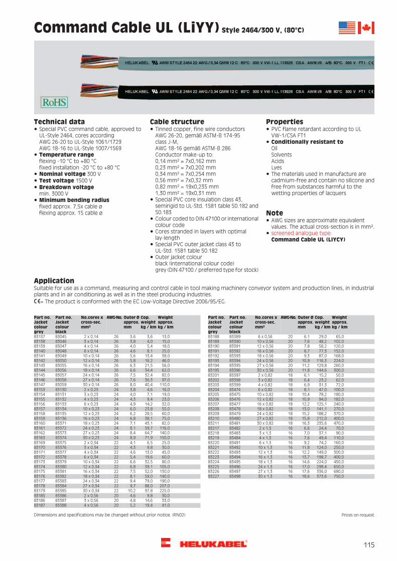
115
Command Cable UL (LiYY) Style 2464/300 V, (80°C)
PropertiesCable structureTechnical dataTinned copper, fine wire conductorsAWG 26-20, gemäß ASTM-B 174-95class J-M,AWG 18-16 gemäß ASTM-B 286Conductor make-up to:0,14 mm² = 7x0,162 mm0,23 mm² = 7x0,202 mm0,34 mm² = 7x0,254 mm0,56 mm² = 7x0,32 mm0,82 mm² = 19x0,235 mm1,30 mm² = 19x0,31 mm
Special PVC command cable, approved toUL-Style 2464, cores accordingAWG 26-20 to UL-Style 1061/1729AWG 18-16 to UL-Style 1007/1569
PVC flame retardant according to ULVW-1/CSA FT1Conditionally resistant toOilSolventsAcidsLyes
Temperature rangeflexing -10 °C to +80 °Cfixed installation -20 °C to +80 °C
The materials used in manufacture arecadmium-free and contain no silicone andfree from substances harmful to thewetting properties of lacquers
Nominal voltage 300 VTest voltage 1500 VBreakdown voltagemin. 3000 V
Special PVC core insulation class 43,semirigid to UL-Std. 1581 table 50.182 and50.183 Note
Minimum bending radiusfixed approx. 7,5x cable øflexing approx. 15 cable ø
Colour coded to DIN 47100 or internationalcolour code
AWG sizes are approximate equivalentvalues. The actual cross-section is in mm².
Cores stranded in layers with optimallay-length
screened analogue type:
Special PVC outer jacket class 43 toUL-Std. 1581 table 50.182Outer jacket colourblack (international colour code)grey (DIN 47100 / preferred type for stock)
ApplicationSuitable for use as a command, measuring and control cable in tool making machinery conveyor system and production lines, in industrialplants and in air conditioning as well as in the steel producing industries.
= The product is conformed with the EC Low-Voltage Directive 2006/95/EG.
Weightapprox.kg / km
Cop.weightkg / km
Outer Øapprox.mm
AWG-No.No.cores xcross-sec.mm²
Part no.Jacketcolourblack
Part no.Jacketcolourgrey
Weightapprox.kg / km
Cop.weightkg / km
Outer Øapprox.mm
AWG-No.No.cores xcross-sec.mm²
Part no.Jacketcolourblack
Part no.Jacketcolourgrey
13,03,63,6262 x 0,148304583137 65,029,06,1206 x 0,568338983188102,048,27,62010 x 0,56833908318915,04,03,8263 x 0,148304683138
18,05,44,0264 x 0,148304783139 120,058,27,82012 x 0,568339183190152,077,38,72016 x 0,56833928319125,08,14,6266 x 0,148304883140
38,013,45,62610 x 0,148304983141 168,087,09,32018 x 0,568339383192224,0116,310,92024 x 0,56833948319346,016,25,82612 x 0,148305083142
56,021,56,32616 x 0,148305583143 260,0129,811,22027 x 0,568339583194300,0144,611,82030 x 0,56833968319562,034,46,62618 x 0,148305683144
82,032,47,52624 x 0,148305783145 50,015,26,1182 x 0,82833978320197,036,37,62627 x 0,148305883146 62,023,26,4183 x 0,828339883202
110,040,48,02630 x 0,148305983147 72,031,36,9184 x 0,82833998320316,04,63,8242 x 0,238313083153 100,047,08,1186 x 0,828347483204
180,078,210,41810 x 0,82834758320519,07,14,0243 x 0,23831318315423,09,44,3244 x 0,238313283155 182,094,010,91812 x 0,828347683206
240,0125,112,21816 x 0,82834778320732,014,24,9246 x 0,23831338315655,023,86,02410 x 0,238313483157 270,0141,113,01818 x 0,828347883208
370,0188,215,21824 x 0,82834798320960,028,56,22412 x 0,23831358315875,038,16,82416 x 0,238313683159 400,0212,015,81827 x 0,828348083210
470,0235,616,31830 x 0,82834818321182,043,17,12418 x 0,238337183160116,059,78,12424 x 0,238337283161 70,024,46,6162 x 1,38348283217140,064,78,42427 x 0,238337383162 90,037,17,0163 x 1,38348383218150,071,98,92430 x 0,238337483163 110,049,47,6164 x 1,3834848321925,06,54,1222 x 0,348337583169 160,074,29,2166 x 1,38349183220
250,0124,011,81610 x 1,3834928322130,09,84,3223 x 0,34833768317045,013,04,6224 x 0,348337783171 300,0149,012,21612 x 1,38349383222
400,0198,713,71616 x 1,3834948322360,019,65,4226 x 0,34833788317280,032,56,62210 x 0,348337983173 450,0224,014,61618 x 1,38349583224
650,0298,417,01624 x 1,38349683225105,039,16,82212 x 0,348338083174130,052,07,52216 x 0,348338183175 680,0336,017,61627 x 1,38349783226
750,0373,618,61630 x 1,38349883227140,059,08,12218 x 0,348338283176190,079,09,42224 x 0,348338383177207,088,09,72227 x 0,348338483178225,097,810,22230 x 0,34833858317930,09,84,6202 x 0,56833868318533,014,64,8203 x 0,56833878318641,019,45,2204 x 0,568338883187
Dimensions and specifications may be changed without prior notice. (RN02)
Command Cable UL (LIYCY)
Prices on request.

116
Command Cable UL (LiYCY) Style 2464, 300V, 80°C,
EMC-preferred type
PropertiesCable structureTechnical dataTinned copper, fine wire conductorsAWG 26-20 gem. ASTM-B 174-95 class J-M,AWG 18-16 gem. ASTM-B 286conductor make-up to0,14 mm² = 7x0,162 mm0,23 mm² = 7x0,202 mm0,34 mm² = 7x0,254 mm0,56 mm² = 7x0,32 mm0,82 mm² = 19x0,235 mm1,30 mm² = 19x0,31 mm
Special PVC command cable, approved toUL-Style 2464, cores accordingAWG 26-20 to UL-Style 1061/1729AWG 18-16 to UL-Style 1007/1569
PVC flame retardant according to ULVW-1/CSA FT1Conditionally resistant toOilSolventsAcidsLyes
Temperature rangeflexing -10 °C to +80 °Cfixed installation -20 °C to +80 °C
The materials used in manufacture arecadmium-free and contain no silicone andfree from substances harmful to thewetting properties of lacquers
Nominal voltage 300 VTest voltage 1500 VBreakdown voltagemin. 3000 V Special PVC core insulation class 43,
semirigid to UL-Std. 1581 table 50.182and 50.183 Note
Minimum bending radiusfixed approx. 7,5 cable øflexing approx. 15 cable ø Colour coded to DIN 47100 or international
colour codeAWG sizes are approximate equivalentvalues. The actual cross-section is in mm².Coupling resistance
max. 250 Ohm/km Cores stranded in layers with optimallay-length
non-screened analogue types:
Seperator-foilDrain wireTinned copper wire braiding, approx. 85coverageSpecial PVC outer jacket class 43 toUL-Std. 1581 table 50.182Outer jacket colourblack (international colour code)grey (DIN 47100 / preferred type fromstock)
ApplicationThis cable type is suitable for use as a flexible connector cable in the fields of electronics, control and command technology as well as formeasuring, signal and impulse transfer. Quick and cost favourable connections through cutting and clamping technics.EMC = Electromagnetic compatibillityTo optimise the EMC features we recommend a large round contact of the copper braiding on both ends.
= The product is conformed with the EC Low-Voltage Directive 2006/95/EG.
Weightapprox.kg / km
Cop.weightkg / km
Outer Øapprox.mm
AWG-No.No.cores xcross-sec.mm²
Part no.Jacketcolourblack
Part no.Jacketcolourgrey
Weightapprox.kg / km
Cop.weightkg / km
Outer Øapprox.mm
AWG-No.No.cores xcross-sec.mm²
Part no.Jacketcolourblack
Part no.Jacketcolourgrey
20,012,63,9262 x 0,148397683254 20,016,14,3242 x 0,23839878327025,018,94,5243 x 0,23839888327125,013,74,2263 x 0,148397783255
28,014,94,4264 x 0,148397883256 30,023,04,8244 x 0,23839898327240,032,85,4246 x 0,23839908327330,018,95,0266 x 0,148397983257
50,029,56,12610 x 0,148398083258 60,050,96,52410 x 0,23839918327470,059,16,72412 x 0,23839928327553,031,46,32612 x 0,148398183259
60,043,96,82616 x 0,148398283260 90,068,47,42416 x 0,238399383276123,079,57,72418 x 0,23839948327770,052,17,12618 x 0,148398383261
100,062,88,02624 x 0,148398483262 131,097,38,82424 x 0,238399583278160,0122,09,02427 x 0,238399683279105,066,38,42627 x 0,148398583263
110,070,48,62630 x 0,148398683264 170,0132,09,32430 x 0,238399783280
Continuation
Command Cable UL (LiYY)
Prices on request.

117
Command Cable UL (LiYCY) Style 2464, 300V, 80°C,
EMC-preferred type
Weightapprox.kg / km
Cop.weightkg / km
Outer Øapprox.mm
AWG-No.No.cores xcross-sec.mm²
Part no.Jacketcolourblack
Part no.Jacketcolourgrey
Weightapprox.kg / km
Cop.weightkg / km
Outer Øapprox.mm
AWG-No.No.cores xcross-sec.mm²
Part no.Jacketcolourblack
Part no.Jacketcolourgrey
40,018,14,6222 x 0,346504483286 60,039,16,5182 x 0,82650668331875,050,06,8183 x 0,82650678331950,022,24,8223 x 0,346504583287
60,028,75,1224 x 0,346504683288 90,059,17,4184 x 0,826506883320125,089,18,8186 x 0,82650698332180,045,46,0226 x 0,346504783289
130,066,17,32210 x 0,346504883290 180,0141,410,91810 x 0,826507083322220,0152,811,21812 x 0,826507183323140,070,87,52212 x 0,346504983291
160,088,48,22216 x 0,346505083292 290,0184,112,91816 x 0,826507283324300,0207,213,51818 x 0,826507383325170,0104,18,72218 x 0,346505183293
220,0129,09,92224 x 0,346505283294 450,0272,615,61824 x 0,826507483326470,0289,115,91827 x 0,826507583327250,0138,410,42227 x 0,346505383295
280,0159,010,92230 x 0,346505483296 490,0317,416,61830 x 0,82650768332850,029,45,1202 x 0,566505583302 90,059,16,9162 x 1,36507783334
160,074,17,3163 x 1,3650788333555,039,75,3203 x 0,56650568330361,046,15,6204 x 0,566505783304 200,096,47,9164 x 1,36507983336
290,0137,49,6166 x 1,3650808333790,066,86,6206 x 0,566505883305133,093,18,12010 x 0,566505983306 450,0191,712,41610 x 1,36508183338
600,0251,712,81612 x 1,36508283339151,0117,48,42012 x 0,566506083307190,0130,49,52016 x 0,566506183308 650,0276,112,81616 x 1,36508383340
680,0364,115,51618 x 1,36508483341216,0151,49,92018 x 0,566506283309339,0237,011,52024 x 0,566506383310 900,0442,418,11624 x 1,36508583342
990,0494,718,71627 x 1,36508683343374,0257,412,02027 x 0,566506483311397,0297,012,42030 x 0,566506583312 1050,0521,419,51630 x 1,36508783344
Dimensions and specifications may be changed without prior notice. (RN02)
Photo: REpower
Prices on request.
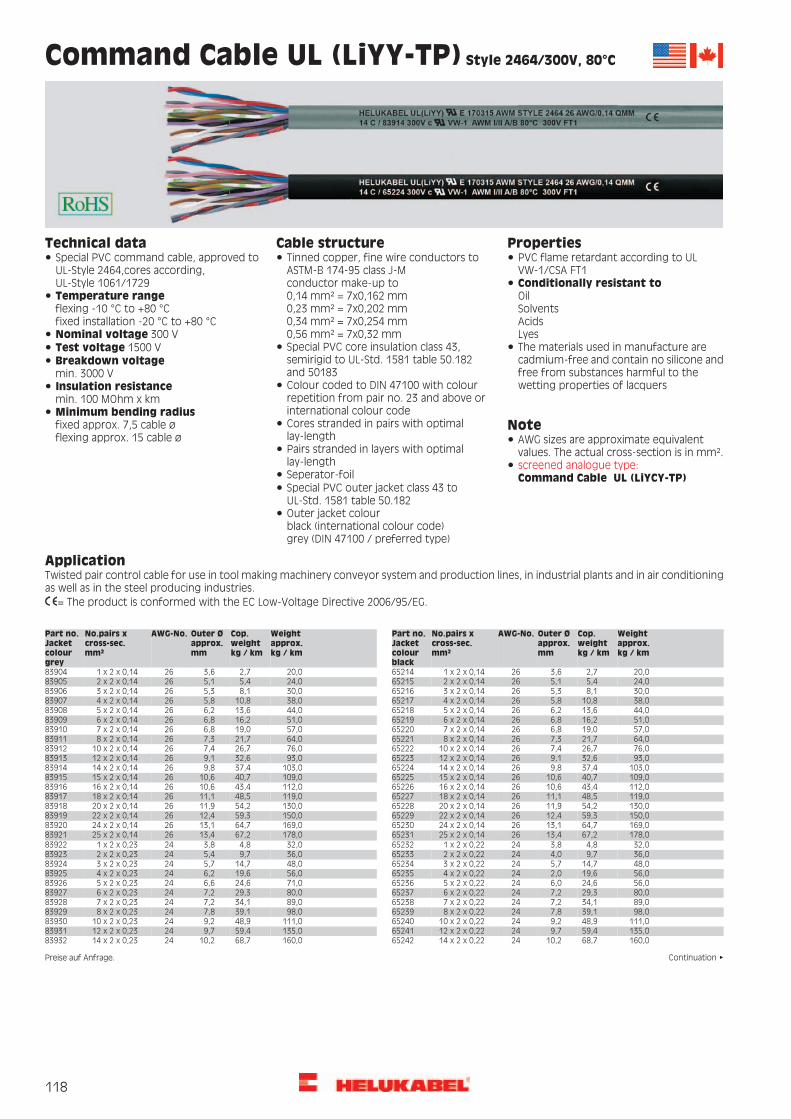
118
Command Cable UL (LiYY-TP) Style 2464/300V, 80°C
PropertiesCable structureTechnical dataTinned copper, fine wire conductors toASTM-B 174-95 class J-Mconductor make-up to0,14 mm² = 7x0,162 mm0,23 mm² = 7x0,202 mm0,34 mm² = 7x0,254 mm0,56 mm² = 7x0,32 mm
Special PVC command cable, approved toUL-Style 2464,cores according,UL-Style 1061/1729
PVC flame retardant according to ULVW-1/CSA FT1Conditionally resistant toOilSolventsAcidsLyes
Temperature rangeflexing -10 °C to +80 °Cfixed installation -20 °C to +80 °CNominal voltage 300 V
Special PVC core insulation class 43,semirigid to UL-Std. 1581 table 50.182and 50183
The materials used in manufacture arecadmium-free and contain no silicone andfree from substances harmful to thewetting properties of lacquers
Test voltage 1500 VBreakdown voltagemin. 3000 V
Colour coded to DIN 47100 with colourrepetition from pair no. 23 and above orinternational colour code
Insulation resistancemin. 100 MOhm x kmMinimum bending radiusfixed approx. 7,5 cable øflexing approx. 15 cable ø
Cores stranded in pairs with optimallay-length
NoteAWG sizes are approximate equivalentvalues. The actual cross-section is in mm².Pairs stranded in layers with optimal
lay-length screened analogue type:Seperator-foilSpecial PVC outer jacket class 43 toUL-Std. 1581 table 50.182Outer jacket colourblack (international colour code)grey (DIN 47100 / preferred type)
ApplicationTwisted pair control cable for use in tool making machinery conveyor system and production lines, in industrial plants and in air conditioningas well as in the steel producing industries.
= The product is conformed with the EC Low-Voltage Directive 2006/95/EG.
Weightapprox.kg / km
Cop.weightkg / km
Outer Øapprox.mm
AWG-No.No.pairs xcross-sec.mm²
Part no.Jacketcolourgrey
Weightapprox.kg / km
Cop.weightkg / km
Outer Øapprox.mm
AWG-No.No.pairs xcross-sec.mm²
Part no.Jacketcolourblack
20,02,73,6261 x 2 x 0,1483904 20,02,73,6261 x 2 x 0,146521424,05,45,1262 x 2 x 0,146521524,05,45,1262 x 2 x 0,1483905
30,08,15,3263 x 2 x 0,1483906 30,08,15,3263 x 2 x 0,146521638,010,85,8264 x 2 x 0,146521738,010,85,8264 x 2 x 0,1483907
44,013,66,2265 x 2 x 0,1483908 44,013,66,2265 x 2 x 0,146521851,016,26,8266 x 2 x 0,146521951,016,26,8266 x 2 x 0,1483909
57,019,06,8267 x 2 x 0,1483910 57,019,06,8267 x 2 x 0,146522064,021,77,3268 x 2 x 0,146522164,021,77,3268 x 2 x 0,1483911
76,026,77,42610 x 2 x 0,1483912 76,026,77,42610 x 2 x 0,146522293,032,69,12612 x 2 x 0,146522393,032,69,12612 x 2 x 0,1483913
103,037,49,82614 x 2 x 0,1483914 103,037,49,82614 x 2 x 0,1465224109,040,710,62615 x 2 x 0,1465225109,040,710,62615 x 2 x 0,1483915
112,043,410,62616 x 2 x 0,1483916 112,043,410,62616 x 2 x 0,1465226119,048,511,12618 x 2 x 0,1465227119,048,511,12618 x 2 x 0,1483917
130,054,211,92620 x 2 x 0,1483918 130,054,211,92620 x 2 x 0,1465228150,059,312,42622 x 2 x 0,1465229150,059,312,42622 x 2 x 0,1483919
169,064,713,12624 x 2 x 0,1483920 169,064,713,12624 x 2 x 0,1465230178,067,213,42625 x 2 x 0,1465231178,067,213,42625 x 2 x 0,1483921
32,04,83,8241 x 2 x 0,226523232,04,83,8241 x 2 x 0,238392236,09,75,4242 x 2 x 0,2383923 36,09,74,0242 x 2 x 0,2265233
48,014,75,7243 x 2 x 0,226523448,014,75,7243 x 2 x 0,238392456,019,66,2244 x 2 x 0,2383925 56,019,62,0244 x 2 x 0,2265235
56,024,66,0245 x 2 x 0,226523671,024,66,6245 x 2 x 0,238392680,029,37,2246 x 2 x 0,2383927 80,029,37,2246 x 2 x 0,2265237
89,034,17,2247 x 2 x 0,226523889,034,17,2247 x 2 x 0,238392898,039,17,8248 x 2 x 0,2383929 98,039,17,8248 x 2 x 0,2265239
111,048,99,22410 x 2 x 0,2265240111,048,99,22410 x 2 x 0,2383930135,059,49,72412 x 2 x 0,2383931 135,059,49,72412 x 2 x 0,2265241
160,068,710,22414 x 2 x 0,2265242160,068,710,22414 x 2 x 0,2383932
Continuation
Command Cable UL (LiYCY-TP)
Preise auf Anfrage.

119
Command Cable UL (LiYY-TP) Style 2464/300V, 80°C
Weightapprox.kg / km
Cop.weightkg / km
Outer Øapprox.mm
AWG-No.No.pairs xcross-sec.mm²
Part no.Jacketcolourgrey
Weightapprox.kg / km
Cop.weightkg / km
Outer Øapprox.mm
AWG-No.No.pairs xcross-sec.mm²
Part no.Jacketcolourblack
171,073,710,92415 x 2 x 0,2383933 171,073,710,92415 x 2 x 0,2265243185,079,110,92416 x 2 x 0,2265244185,079,110,92416 x 2 x 0,2383934
209,088,911,52418 x 2 x 0,2383935 209,088,911,52418 x 2 x 0,2265245230,098,412,22420 x 2 x 0,2265246230,098,412,22420 x 2 x 0,2383936
248,0108,613,02422 x 2 x 0,2383937 248,0108,613,02422 x 2 x 0,2265247279,0117,97,02424 x 2 x 0,2265248279,0117,913,72424 x 2 x 0,2383938
292,0123,514,22425 x 2 x 0,2383939 292,0123,513,72425 x 2 x 0,226524938,06,54,2221 x 2 x 0,3483940 38,06,54,2221 x 2 x 0,3465250
44,013,05,9222 x 2 x 0,346525144,013,05,9222 x 2 x 0,348394160,019,56,3223 x 2 x 0,3483942 60,019,56,3223 x 2 x 0,3465252
79,026,17,0224 x 2 x 0,346525379,026,17,0224 x 2 x 0,348394392,032,67,6225 x 2 x 0,3483944 92,032,67,6225 x 2 x 0,3465254
119,039,28,2226 x 2 x 0,3465255119,039,28,2226 x 2 x 0,3483945128,045,78,2227 x 2 x 0,3483946 128,045,78,2227 x 2 x 0,3465256
139,052,39,0228 x 2 x 0,3465257139,052,39,0228 x 2 x 0,3483947171,065,310,72210 x 2 x 0,3483948 171,065,310,72210 x 2 x 0,3465258
194,078,411,32212 x 2 x 0,3465259194,078,411,32212 x 2 x 0,3483949222,091,512,12214 x 2 x 0,3483950 222,091,512,12214 x 2 x 0,3465260
231,097,812,72215 x 2 x 0,3465261231,097,812,72215 x 2 x 0,3483951240,0104,612,72216 x 2 x 0,3483952 240,0104,612,72216 x 2 x 0,3465262
264,0117,813,62218 x 2 x 0,3465263264,0117,813,62218 x 2 x 0,3483953291,0130,714,42220 x 2 x 0,3483954 291,0130,714,42220 x 2 x 0,3465264
300,0143,615,12222 x 2 x 0,3465265300,0143,615,12222 x 2 x 0,3483955359,0156,816,22224 x 2 x 0,3483956 359,0156,816,22224 x 2 x 0,3465266
381,0163,316,72225 x 2 x 0,3465267381,0163,316,72225 x 2 x 0,348395760,010,84,6201 x 2 x 0,566526860,010,84,6201 x 2 x 0,5683958
80,021,56,5202 x 2 x 0,5683959 80,021,56,5202 x 2 x 0,566526994,032,37,1203 x 2 x 0,566527094,032,37,1203 x 2 x 0,5683960
104,043,17,8204 x 2 x 0,5683961 104,043,17,8204 x 2 x 0,5665271130,053,88,6205 x 2 x 0,5665272130,053,88,6205 x 2 x 0,5683962
151,064,69,6206 x 2 x 0,5683963 151,064,69,6206 x 2 x 0,5665273174,075,39,6207 x 2 x 0,5665274174,075,39,6207 x 2 x 0,5683964
262,086,112,2208 x 2 x 0,5683965 262,086,112,1208 x 2 x 0,5665275298,0107,712,52010 x 2 x 0,5665276298,0107,712,52010 x 2 x 0,5683966
302,0129,113,12012 x 2 x 0,5683967 302,0129,113,12012 x 2 x 0,5665277327,0150,613,82014 x 2 x 0,5665278327,0150,613,82014 x 2 x 0,5683968
370,0161,314,72015 x 2 x 0,5683969 370,0161,314,72015 x 2 x 0,5665279402,0172,114,72016 x 2 x 0,5665280402,0172,114,72016 x 2 x 0,5683970
480,0193,615,72018 x 2 x 0,5683971 480,0193,615,72018 x 2 x 0,5665281551,0215,116,72020 x 2 x 0,5665282551,0215,116,72020 x 2 x 0,5683972
621,0236,617,22022 x 2 x 0,5683973 621,0236,617,22022 x 2 x 0,5665283703,0258,018,62024 x 2 x 0,5665284703,0258,018,62024 x 2 x 0,5683974
721,0268,919,22025 x 2 x 0,5683975 721,0268,919,22025 x 2 x 0,5665285
Dimensions and specifications may be changed without prior notice. (RN02) Prices on request.

120
Command Cable UL (LiYCY-TP) Style 2464/300 V, 80°C,
EMC-preferred type
PropertiesCable structureTechnical dataTinned copper, fine wire conductors toASTM-B 174-95 class J-MConductor make-up to0,14 mm² = 7x0,162 mm0,23 mm² = 7x0,202 mm0,34 mm² = 7x0,254 mm0,56 mm² = 7x0,32 mm
Special PVC command cable, approved toUL-Style 2464,cores according,UL-Style 1061/1729
PVC flame retardant according to ULVW-1/CSA FT1Conditionally resistant toOilSolventsAcidsLyes
Temperature rangeflexing -10 °C to +80 °Cfixed installation -20 °C to +80 °CNominal voltage 300 V
Special PVC core insulation class 43,semirigid to UL-Std. 1581 table 50.182and 50183
The materials used in manufacture arecadmium-free and contain no silicone andfree from substances harmful to thewetting properties of lacquers
Test voltage 1500 VBreakdown voltagemin. 3000 V
Colour coded to DIN 47100 with colourrepetition from pair no. 22 and above orinternational colour code
Insulation resistancemin. 100 MOhm x km
NoteMinimum bending radiusfixed approx. 7,5 cable øflexing approx. 15 cable ø
Cores stranded in pains with optimallay-length
AWG sizes are approximate equivalentvalues. The actual cross-section is in mm².
Pains stranded in layers with optimallay-length
Coupling resistancemax. 250 Ohm/km
non-screened analogue type: UL (LiYY-TP)
Seperator-foilDrain wireTinned copper wire braiding, approx. 85coverageSpecial PVC outer jacket class 43 toUL-Std. 1581 table 50.182Outer jacket colourblack (international colour code)grey (DIN 47100 / preferred type fromstock)
ApplicationTwisted pair control cable for use in tool making machinery conveyor system and production lines, in industrial plants and in air conditioningas well as in the steel producing industries.EMC = Electromagnetic compatibillityTo optimise the EMC features we recommend a large round contact of the copper braiding on both ends.
= The product is conformed with the EC Low-Voltage Directive 2006/95/EG.
Weightapprox.kg / km
Cop.weightkg / km
Outer Øapprox.mm
AWG-No.No.pairs xcross-sec.mm²
Part no.Jacketcolourblack
Jacketcolourgrey
Weightapprox.kg / km
Cop.weightkg / km
Outer Øapprox.mm
AWG-No.No.pairs xcross-sec.mm²
Part no.Jacketcolourblack
Jacketcolourgrey
32,015,74,0261 x 2 x 0,146531483774 46,016,44,2241 x 2 x 0,23653328379253,027,45,9242 x 2 x 0,23653338379339,019,55,6262 x 2 x 0,146531583775
47,023,75,8263 x 2 x 0,146531683776 65,031,76,2243 x 2 x 0,23653348379479,037,46,7244 x 2 x 0,23653358379555,026,96,3264 x 2 x 0,146531783777
68,031,26,7265 x 2 x 0,146531883778 98,054,77,2245 x 2 x 0,236533683796114,065,67,7246 x 2 x 0,23653378379786,049,77,3266 x 2 x 0,146531983779
92,052,07,3267 x 2 x 0,146532083780 121,060,27,7247 x 2 x 0,236533883798129,074,18,4248 x 2 x 0,23653398379997,053,97,8268 x 2 x 0,146532183781
111,059,69,12610 x 2 x 0,146532283782 152,0109,39,92410 x 2 x 0,236534083800189,0115,810,22412 x 2 x 0,236534183801141,067,19,82612 x 2 x 0,146532383783
150,075,210,52614 x 2 x 0,146532483784 213,0120,710,92414 x 2 x 0,236534283802225,0132,411,42415 x 2 x 0,236534383803154,077,311,12615 x 2 x 0,146532583785
155,080,411,12616 x 2 x 0,146532683786 227,0141,611,42416 x 2 x 0,236534483804238,0146,612,22418 x 2 x 0,236534583805170,084,211,82618 x 2 x 0,146532783787
183,098,212,42620 x 2 x 0,146532883788 270,0160,612,72420 x 2 x 0,236534683806300,0170,813,52422 x 2 x 0,236534783807207,0104,113,12622 x 2 x 0,146532983789
228,0112,013,62624 x 2 x 0,146533083790 321,0229,714,52424 x 2 x 0,236534883808340,0231,414,82425 x 2 x 0,236534983809239,0114,415,12625 x 2 x 0,146533183791
Continuation
Command Cable
Prices on request.

121
Command Cable UL (LiYCY-TP) Style 2464/300 V, 80°C,
EMC-preferred type
Weightapprox.kg / km
Cop.weightkg / km
Outer Øapprox.mm
AWG-No.No.pairs xcross-sec.mm²
Part no.Jacketcolourblack
Jacketcolourgrey
Weightapprox.kg / km
Cop.weightkg / km
Outer Øapprox.mm
AWG-No.No.pairs xcross-sec.mm²
Part no.Jacketcolourblack
Jacketcolourgrey
58,017,04,6221 x 2 x 0,346535083810 70,026,05,0201 x 2 x 0,56653688382889,056,17,0202 x 2 x 0,56653698382965,036,76,4222 x 2 x 0,346535183811
78,044,66,9223 x 2 x 0,346535283812 102,071,77,6203 x 2 x 0,566537083830119,092,48,3204 x 2 x 0,56653718383188,054,17,5224 x 2 x 0,346535383813
110,063,48,1225 x 2 x 0,346535483814 140,0107,49,1205 x 2 x 0,566537283832162,0122,410,1206 x 2 x 0,566537383833126,073,48,8226 x 2 x 0,346535583815
140,079,48,8227 x 2 x 0,346535683816 198,0131,710,1207 x 2 x 0,566537483834272,0144,312,7208 x 2 x 0,566537583835148,088,49,7228 x 2 x 0,346535783817
184,0107,011,52210 x 2 x 0,346535883818 307,0179,613,22010 x 2 x 0,566537683836318,0201,713,62012 x 2 x 0,566537783837210,0122,412,02212 x 2 x 0,346535983819
241,0138,212,62214 x 2 x 0,346536083820 342,0221,414,42014 x 2 x 0,566537883838381,0231,615,52015 x 2 x 0,566537983839245,0154,313,42215 x 2 x 0,346536183821
251,0161,413,42216 x 2 x 0,346536283822 417,0257,115,52016 x 2 x 0,566538083840494,0282,416,32018 x 2 x 0,566538183841275,0197,914,42218 x 2 x 0,346536383823
300,0211,415,02220 x 2 x 0,346536483824 570,0306,717,12020 x 2 x 0,566538283842643,0321,818,02022 x 2 x 0,566538383843320,0217,615,92222 x 2 x 0,346536583825
371,0230,417,02224 x 2 x 0,346536683826 724,0342,419,42024 x 2 x 0,566538483844740,0361,219,82025 x 2 x 0,566538583845402,0138,517,32225 x 2 x 0,346536783827
Dimensions and specifications may be changed without prior notice. (RN02)
Photo: HELUKABEL®
Prices on request.

122
SUPERTRONIC®-PURö special cable for drag chains, meter marking
PropertiesCable structureTechnical dataBare copper, extra fine wire conductors,to DIN VDE 0295 cl. 6, col. 4 and 5, cl. 6 andIEC 60228 cl. 6
Special PUR drag chain cables adapted toDIN VDE 0281 part 13
FeaturesHigh flexibility at low temperature, highabrasion resistance, break and cut-resistant,tear resistant, flame retardant.
Very high flexible due to specialconstruction Oil resistant PVC core insulation TI2, in
adapted to DIN VDE 0281 part 1, for bettersliding abilities
Temperature rangeflexing -5 °C to +70 °Cfixed installation -40 °C to +70 °C
Resistant to UV-radiation, Oxygen, Ozone,Hydrolyse, Oil.
Cores are stranded in layer with shortlay-length
Conditional resistant to Microbes,Hydraulic liquidity, Alkalis, Lye.Nominal voltage 350 V
Cores colour coded to DIN 47100 The PUR outer jacket is extremely robustwith high tear, abrasion and oil-resistance.Adhesion-free.
Test voltage 1500 VCore wrapping with textile tapeBreakdown voltage min. 3000 VSpecial full-polyurethane outer jacketTMPU to DIN VDE 0282 part 10, appendix A
Insulation resistancemin. 20 MOhm x km The materials used in manufacture are
cadmium-free and contain no silicone andOuter jacket grey (RAL 7001), surface matMinimum bending radiusflexing 5x cable øfixed installation 3x cable ø
free from substances harmful to thewetting properties of lacquers
with meter marking, change-over in 2011
Radiation resistanceup to 100x106 cJ/kg (up to 100 Mrad) Note
AWG sizes are approximate equivalentvalues. The actual cross-section is in mm².
ApplicationPerfect for use with cable trays. This highly flexible and screened PUR control cable is ideal for use wherever frequent high flexing motionis required, e.g. in robotics or all moving parts. The long working life of this cable makes it both efficient and economic.For applications which go beyond standard solutions (for example for composting appliances or high shelf conveyors with extremely highprocessing speeds etc.) we recommend for our especially developed enquiry sheet for energy guiding systems.Before installation in cable trays please read the instructions. Further technical details see selection table for drag chain cables, see lead text.
= The product is conformed with the EC Low-Voltage Directive 2006/95/EG.
AWG-No.Weightapprox.kg / km
Cop.weightkg / km
Outer Øapprox. mm
No.cores xcross-sec.mm²
Part no. AWG-No.Weightapprox.kg / km
Cop.weightkg / km
Outer Øapprox. mm
No.cores xcross-sec.mm²
Part no.
2622,02,83,52 x 0,1449583 2491,030,17,612 x 0,254960024102,035,07,914 x 0,25496012624,04,13,73 x 0,1449584
2629,05,63,94 x 0,1449585 24125,045,08,918 x 0,254960224163,060,010,024 x 0,25496032633,07,04,25 x 0,1449586
2647,09,84,97 x 0,1449587 24170,062,510,625 x 0,25496042659,014,06,210 x 0,1449588 2232,06,84,52 x 0,34496052667,016,86,412 x 0,1449589 2240,010,24,93 x 0,34496062674,019,66,614 x 0,1449590 2255,013,65,34 x 0,34496072686,025,27,318 x 0,1449591 2260,017,05,85 x 0,344960826115,033,68,524 x 0,1449592 2280,023,86,97 x 0,344960926120,035,08,625 x 0,1449593 22112,034,08,410 x 0,34496102427,05,04,12 x 0,2549594 22127,040,88,612 x 0,3449611
22142,047,69,014 x 0,34496122433,07,54,33 x 0,25495952440,010,04,84 x 0,2549596 22175,061,210,118 x 0,3449613
22229,081,512,024 x 0,34496142448,012,55,25 x 0,25495972460,017,56,27 x 0,2549598 22238,085,012,225 x 0,34496152479,025,07,410 x 0,2549599
Dimensions and specifications may be changed without prior notice. (RC03) Prices on request.

123
SUPERTRONIC®-C-PURö special cable for drag chains,
halogen-free, EMC-preferred type, meter marking
PropertiesCable structureTechnical dataPlain copper conductors extra fine wirestranded to DIN VDE 0295 cl. 6, col. 4 and5, IEC 60228 cl. 6
Special PUR drag chain cables, screened, inadapted to DIN VDE 0281 part 13
FeaturesHigh flexibility at low temperature, highabrasion resistance, break and cut-resistant,tear resistant, flame retardant.
Temperature rangeflexing -40 °C to +70 °Cfixed installation -50 °C to +70 °C
Oil resistant TPE core insulationResistant to UV-radiation, Oxygen, Ozone,Hydrolyse, Oil.
Cores are stranded in layer with shortlay-lengthNominal voltage
0,14 mm² 350 V0,25 and 0,34 mm² 500 V
Conditional resistant to Microbes,Hydraulic liquidity, Alkalis, Lye.
Cores colour coded to DIN 47100Core wrapping with textile tape
The PUR outer jacket is extremely robustwith high tear, abrasion and oil-resistance.
Test voltage0,14 mm² 800 V0,25 and 0,34 mm² 1200 V
Tinned copper screened braiding. Due tothe technical facilities, the copper braidingcan be mixed and webed with a portion ofsynthetic fibres
Adhesion-free.Capacitance core/core 80 nF/km The materials used in manufacture are
cadmium-free and contain no silicone andMinimum bending radiusflexing 7,5x cable øfixed installation 4x cable ø
Special full-polyurethane outer jacketTMPU to DIN VDE 0282 part 10, appendix A free from substances harmful to the
wetting properties of lacquersOuter jacket grey (RAL 7001)Radiation resistanceup to 100x10
with meter marking, change-over in 2011Note
AWG sizes are approximate equivalentvalues. The actual cross-section is in mm².
ApplicationUsed for installation in dry, moist and wet environments as well as for outdoors, for free movement without forced motion and for flexiblerouting without forced motion, for proven use as drag-chain cables. Suitable as a highly flexible control cable for fast hoisting and bendingstresses in machinery and tooling construction, in robotics engineering and for continuously moving machinery parts.The long working life of this cable makes it both efficient and economic. The copper braided screening offers effective protection fromboth internal and external interference.For applications which go beyond standard solutions (for example for composting appliances or high shelf conveyors with extremely highprocessing speeds etc.) we recommend for our especially developed enquiry sheet for energy guiding systems.Before installation in cable trays please read the instructions. Further technical details see selection table for drag chain cables, see lead text.EMC = Electromagnetic compatibillityTo optimise the EMC features we recommend a large round contact of the copper braiding on both ends.
= The product is conformed with the EC Low-Voltage Directive 2006/95/EG.
AWG-No.Weightapprox.kg / km
Cop.weightkg / km
Outer Øapprox. mm
No.cores xcross-sec.mm²
Part no. AWG-No.Weightapprox.kg / km
Cop.weightkg / km
Outer Øapprox. mm
No.cores xcross-sec.mm²
Part no.
2632,011,24,12 x 0,1449653 24124,059,18,412 x 0,254967024135,064,28,714 x 0,25496712635,014,14,33 x 0,1449654
2640,015,54,54 x 0,1449655 24160,078,49,518 x 0,254967224202,089,911,024 x 0,25496732645,018,34,85 x 0,1449656
2666,027,85,77 x 0,1449657 24211,0101,011,125 x 0,25496742686,039,36,710 x 0,1449658 2245,018,15,02 x 0,34496752694,042,16,912 x 0,1449659 2260,028,75,43 x 0,344967626102,045,37,114 x 0,1449660 2276,035,76,24 x 0,344967726118,054,17,818 x 0,1449661 2282,039,16,75 x 0,344967826149,066,39,024 x 0,1449662 22110,052,77,67 x 0,344967926156,068,49,125 x 0,1449663 22148,067,49,210 x 0,34496802438,014,94,62 x 0,2549664 22166,076,49,412 x 0,3449681
22185,085,510,014 x 0,34496822444,018,84,83 x 0,25496652451,021,35,34 x 0,2549666 22216,099,710,918 x 0,3449683
22300,0147,112,624 x 0,34496842468,031,05,75 x 0,25496672482,039,66,77 x 0,2549668 22313,0155,012,825 x 0,344968524110,053,98,210 x 0,2549669
Dimensions and specifications may be changed without prior notice. (RC03) Prices on request.

124
SUPERTRONIC-330 PURö cable for drag chains,
halogen-free, meter marking
PropertiesCable structureTechnical dataBare copper, extra fine-wire toDIN VDE 0295 cl. 6, col. 4, BS 6360 cl. 6
Special PUR sheathed cable PUR flame retardant according to VDE0482-332-1-2, DIN EN 60332-1-2/IEC 60332-1 (equivalent DIN VDE 0472part 804 test method B)
Temperature rangeflexing -40 °C to +80 °Cfixed -50 °C to +80 °C
Polyolefine core insulationCores stranded in layers with optimallyadjusted lay-lengths Low adhesionNominal voltage 300 V
High flexibility at low temperaturesCores colour coded to DIN 47100Test voltagecore/core 1500 V High abrasion resistanceFoil wrapping over the outer layerInsulation resistancemin. 100 MOhm x km
Tear and cut-resistantSpecial full-polyurethane outer sheathTMPU to DIN VDE 0282 Part 10, Annex Aand acc. to UL std. 1581 Tab. 50227 80 °C
Notch resistantCapacitancecore/core 60 nF/km
Resistant toUV-radiation, Oxygen, Ozone, Hydrolysis,Oil
Sheath colour grey (RAL 7001)Minimum bending radiusflexing 5 x cable øfixed 3 x cable ø
with meter marking, change-over in 2011Partially resistant toMicrobial attack, Hydraulic fluids, Coolantemulsion, AlkalisRadiation resistance
up to 100x106 cJ/kg (up to 100 Mrad) The materials used in manufacture aresilicon and cadmium-free and contain nosubstances harmful to the wettingproperties of lacquers
ApplicationFor installation in dry, moist and wet rooms and outdoors with free movement without tensile stress or forced movements, impressivelyproven in drag chain application.A highly flexible PUR control cable, suitable for frequent and quick lifting and bending stresses in machine engineering and construction,in robot technology and on permanently moving machine components. Long service life guarantees reliable function and high cost-efficiency.For applications which go beyond standard solutions (for example for composting appliances or high shelf conveyors with extremely highprocessing speeds etc.) we recommend for our especially developed enquiry sheet for energy guiding systems. Before installation in cabletrays please read the instructions. Further technical details see selection table for drag chain cables, see lead text.Attractive for export-oriented mechanical engineering.
= The product is conformed with the EC Low-Voltage Directive 2006/95/EG.
Weightapprox.kg / km
Cop.weightkg / km
Outer Øapprox. mm
AWG-No.No.cores xcross-sec.mm²
Part no. Weightapprox.kg / km
Cop.weightkg / km
Outer Øapprox. mm
AWG-No.No.cores xcross-sec.mm²
Part no.
22,02,83,9262 x 0,1449764 97,035,07,42414 x 0,2549782114,045,08,22418 x 0,254978324,04,14,0263 x 0,1449765
29,05,64,3264 x 0,1449766 157,060,09,62424 x 0,2549784160,062,510,12425 x 0,254978533,07,04,7265 x 0,1449767
47,09,85,3267 x 0,1449768 31,06,84,6222 x 0,344978657,014,06,12610 x 0,1449769 38,010,24,8223 x 0,344978763,016,86,22612 x 0,1449770 51,013,65,2224 x 0,344978872,019,66,52614 x 0,1449771 54,017,05,6225 x 0,344978980,025,27,22618 x 0,1449772 77,023,86,5227 x 0,3449790
110,033,68,22624 x 0,1449773 104,034,07,52210 x 0,3449791115,035,08,62625 x 0,1449774 122,040,87,72212 x 0,3449792
26,05,04,3242 x 0,2549775 140,047,68,12214 x 0,3449793162,061,29,22218 x 0,344979430,07,54,5243 x 0,2549776
39,010,04,8244 x 0,2549777 204,081,510,72224 x 0,3449795229,085,011,22225 x 0,344979644,012,55,2245 x 0,2549778
52,017,56,0247 x 0,254977970,025,06,92410 x 0,254978084,030,17,12412 x 0,2549781
Dimensions and specifications may be changed without prior notice. (RN05) Prices on request.

125
SUPERTRONIC-330 C-PURö cable for drag chains,
halogen-free, EMC-preferred type, meter marking
PropertiesCable structureTechnical dataBare copper conductor, extra fine wire toDIN VDE 0295 cl. 6, col. 4, BS 6360 cl. 6
Special PUR sheathed cable, screened Flame retardant according to VDE0482-332-1-2, DIN EN 60332-1-2/IEC 60332-1 (equivalent DIN VDE 0472part 804 test method B)
Temperature rangeflexing -40 °C to +80 °Cfixed -50 °C to +80 °C
Polyolefine core insulationColour coded to DIN 47100
Low-adhesionNominal voltage 300 V Cores stranded in layers with optimallay-length High flexibility at low temperaturesTest voltage
core/core 1500 Vcore/screen 1000 V
High abrasion resistanceWrapping over the outer layerTear and cut-resistantBraided screen of tinned Cu wires,
coverage approx. 85Insulation resistancemin. 100 MOhm x km
Notch resistantCore wrapping with fleece Resistant to
UV-radiation, Oxygen, Ozone, Hydrolysis,Oil
Capacitancecore/core 60 nF/km
Special full polyurethane outer sheathTMPU acc. to DIN VDE 0281 Part 10,Annex A and acc. to UL std. 1581 Tab. 5022780 °C
Minimum bending radiusflexing 7,5 x cable øfixed 4 x cable ø
Partially resistant toMicrobial attack, Hydraulic fluid, Coolantemulsion, AlkalisSheath colour grey (RAL 7001)
Radiation resistanceup to 100x106 cJ/kg (up to 100 Mrad)
with meter marking, change-over in 2011 The materials used in manufacture arecadmium-free and contain no silicone and
Coupling resistancemax. 250 Ohm/km
free from substances harmful to thewetting properties of lacquers
ApplicationEspecially suited for drag chain installation in dry, moist and wet environments and outdoors with flexible movement and without tensilestress or forced movements. A highly-flexible PVC control cable suitable for frequent and fast lifting and bending stresses in machines andtool building, robot systems and on constantly moving machine components. Long service lives guarantee reliable function and good costefficiency. The dense screening assures interference-free transmission of all signals and impulses. An ideal interference-free control cablefor the above applications.For applications which go beyond standard solutions (for example for composting appliances or high shelf conveyors with extremely highprocessing speeds etc.) we recommend for our especially developed enquiry sheet for energy guiding systems. Before installation in cabletrays please read the instructions. Further technical details see selection table for drag chain cables, see lead text.EMC = Electromagnetic compatibilityTo optimise the EMC characteristics we recommend a large area of contact of the copper braiding around the entire circumference on bothends.
= The product is conformed with the EC Low-Voltage Directive 2006/95/EG.
Weightapprox.kg / km
Cop.weightkg / km
Outer Øapprox. mm
AWG-No.No.cores xcross-sec.mm²
Part no. Weightapprox.kg / km
Cop.weightkg / km
Outer Øapprox. mm
AWG-No.No.cores xcross-sec.mm²
Part no.
32,011,24,4262 x 0,1449797 135,064,28,02414 x 0,2549815150,078,48,82418 x 0,254981635,014,14,5263 x 0,1449798
40,015,54,8264 x 0,1449799 194,089,910,22424 x 0,2549817204,0101,010,72425 x 0,254981845,018,35,0265 x 0,1449800
66,027,85,8267 x 0,1449801 45,018,15,1222 x 0,344981986,039,36,72610 x 0,1449802 60,028,75,3223 x 0,344982094,042,16,82612 x 0,1449803 76,035,75,7224 x 0,3449821
102,045,37,12614 x 0,1449804 82,039,16,1225 x 0,3449822118,054,17,82618 x 0,1449805 110,052,77,1227 x 0,3449823149,066,38,82624 x 0,1449806 148,067,48,12210 x 0,3449824156,068,49,22625 x 0,1449807 166,076,48,32212 x 0,3449825
38,014,94,8242 x 0,2549808 185,085,58,72214 x 0,3449826216,099,79,82218 x 0,344982744,018,85,0243 x 0,2549809
51,021,35,3244 x 0,2549810 291,0147,111,32224 x 0,3449828305,0155,011,82225 x 0,344982968,031,05,7245 x 0,2549811
82,039,66,6247 x 0,2549812110,053,97,52410 x 0,2549813124,059,17,72412 x 0,2549814
Dimensions and specifications may be changed without prior notice. (RN05) Prices on request.

126
SUPER-PAAR-TRONIC-C-PUR cable for drag chains,
halogen-free, EMC-preferred type, meter marking
PropertiesCable structureTechnical dataPlain copper conductors, extra fine wirestranded to DIN VDE 0295 cl. 6, col. 4,BS 6360 cl. 6 and IEC 60228 cl. 6
Special PETP-PUR cable, twisted inpairs,adapted to DIN VDE 0245, 0812
Very good oil resistant, test methodaccording to DIN VDE 0472 part 803Resistant to weather, ozone andUV-radiation
Conductor and loop resistance as perDIN VDE 0295, for 0,25 mm² see pagesTechnical-Informations
Special core insulation of TPEChemical resistant to solvents, acids, lyesand hydraulic liquidity
Core identification as per DIN 47100Temperature rangeflexing -40 °C to +70 °Cfixed installation -50 °C to +70 °C
Cores twisted in pairs, the pairs torsion-freestranded in layers Flame retardant
Guaranteed permanent application inmulti-shift operation under extreme highbending stress
Special fleece over outer layerNominal voltage 350 V Tinned copper screened braiding, approx.
85 coverageTest voltage 1500 VHigh resistant to mechanical strainInsulation resistance
min. 100 MOhm x kmFull-polyurethane outer jacket TMPU, toDIN VDE 0282 part 10, appendix A High property of alternating bending
strengthMutual capacitanceapprox. 135 nF/km
Outer jacket grey (RAL 7001)Long life durabilities through lowfriction-resistance by using the TPE-core
with meter marking, change-over in 2011Minimum bending radiusflexing at 0,25 mm²approx. 7,5xcable øfixed installation at 0,25 mm²approx. 4xcable øflexing at 0,5-1,0 mm²approx. 10xcable øfixed installation at 0,5-1,0 mm²approx. 5xcable ø
insulation where the core are stranded inlayersHigh tensile strength-, abrasion- andimpact resistant at low temperatureAdhesion-lowThe materials used in manufacture arecadmium-free and contain no silicone andfree from substances harmful to thewetting properties of lacquersCoupling resistance
max. 250 Ohm/km
NoteRadiation resistanceup to 100x106 cJ/kg (up to 100 Mrad) AWG sizes are approximate equivalent
values. The actual cross-section is in mm².
ApplicationThese pair stranded and overall screened special cables for drag chains offer the operational possibilities where the outer electrical influencesat high frequence cause interference of impulse transmission, are applied for permanent flexible operations in machineries, machine tools,robot technics, for movable automated machinery parts and multi-shift-operation as a transmission-cable.These high flexible data cables are developed according to the newest state of technology improvement and with its sliding abilities by usingthe PETP-core insulation and adhesion-low and cut-resistant PUR-outer jacket, guaranteed an optimum life durabilities and highly economic.For applications which go beyond standard solutions (for example for composting appliances or high shelf conveyors with extremely highprocessing speeds etc.) we recommend for our especially developed enquiry sheet for energy guiding systems.Before installation in cable trays please read the instructions. Further technical details see selection table for drag chain cables, see lead text.EMC = Electromagnetic compatibillityTo optimise the EMC features we recommend a large round contact of the copper braiding on both ends.
= The product is conformed with the EC Low-Voltage Directive 2006/95/EG.
AWG-No.Weightapprox.kg / km
Cop.weightkg / km
Outer Øapprox.mm
No.pairs xcross-sec.mm²
Part no. AWG-No.Weightapprox.kg / km
Cop.weightkg / km
Outer Øapprox.mm
No.pairs xcross-sec.mm²
Part no.
2428,014,04,71 x 2 x 0,2519101 1861,034,06,31 x 2 x 0,751912818113,060,09,02 x 2 x 0,75191292461,032,06,52 x 2 x 0,2519102
2473,038,46,63 x 2 x 0,2519103 18158,085,79,13 x 2 x 0,751913018173,093,69,94 x 2 x 0,75191312490,043,27,14 x 2 x 0,2519104
24105,051,58,25 x 2 x 0,2519105 18203,0113,011,55 x 2 x 0,751913218231,0130,411,96 x 2 x 0,751913324133,071,88,56 x 2 x 0,2519106
24156,074,49,28 x 2 x 0,2519107 18343,0192,213,18 x 2 x 0,751913418467,0258,015,010 x 2 x 0,751913524188,090,010,710 x 2 x 0,2519108
24220,0111,211,514 x 2 x 0,2519109 18546,0316,616,414 x 2 x 0,75191362047,022,05,51 x 2 x 0,519119 1771,042,06,91 x 2 x 119137
17130,073,010,02 x 2 x 11913820100,050,07,92 x 2 x 0,51912020131,071,88,23 x 2 x 0,519121 17170,093,610,23 x 2 x 119139
17204,0117,811,34 x 2 x 11914020149,074,48,94 x 2 x 0,51912220169,084,510,35 x 2 x 0,519123 17238,0139,013,15 x 2 x 11914120196,099,610,76 x 2 x 0,51912420285,0144,311,88 x 2 x 0,51912520344,0176,013,510 x 2 x 0,51912620401,0215,414,814 x 2 x 0,519127
Dimensions and specifications may be changed without prior notice. (RC03) Prices on request.

127
Prices on request.
SUPER-PAAR-TRONIC 340-C-PUR cable for drag
chains, halogen-free, EMC-preferred type, meter marking
PropertiesCable structureTechnical dataBare copper conductor, fine or extrafine wire to DIN VDE 0295 cl. 6, col. 4,BS 6360 cl. 6 and IEC 60228 cl. 6
Special drag chain cable, stranded in pairs Flame retardant according to VDE0482-332-1-2, DIN EN 60332-1-2/IEC 60332-1 (equivalent DIN VDE 0472part 804 test method B)
Temperature rangeflexing -20 °C to +80 °Cfixed -40 °C to +80 °C Polyolefin core insulation
Oil resistance according to IEC 60092-350Colour coded to DIN 47100Nominal voltage 300 VHalogen freeCores stranded in pairs, pairs stranded
torsion-free in layers with optimallay-length
Test voltagecore/core 1500 Vcore/screen 1000 V
Weather, ozone and UV-resistantChemical resistance to solvents, acids,alkalis and hydraulic fluidsCore wrapping between the layers of
strandingInsulation resistancemin. 100 MOhm x km The materials used in manufacture are
cadmium-free and contain no silicone andBraided screen of tinned Cu wires,coverage approx. 85
Mutual capacitancecore/core approx. 60 nF/km free from substances harmful to the
wetting properties of lacquersCore wrapping with fleeceMinimum bending radiusfor permanent bendingat 0,25 mm²flexing 7,5x cable øfixed 4x cable øat 0,5-1,0 mm²flexing 10x cable øfixed 5x cable ø
AdvantagesFull polyurethane outer sheath TMPUacc. to DIN VDE 0281 Part 10, Annex A andacc. to UL std. 1581 Tab. 50227 80 °C
Very high resistance to mechanical stressesVery good alternating bending strength
Sheath colour grey (RAL 7001) High tear, abrasion and impact resistance,even at low temperatureswith meter marking, change-over in 2011
Coupling resistancemax. 250 Ohm/kmRadiation resistanceup to 100x106 cJ/kg (up to 100 Mrad)
ApplicationStranded in pairs, these fully-screened special drag chain cables can also be used where external, high-frequency interference influencespulse transfer. They are used for permanently flexible stresses in machine and tool building, in robot technology, on constantly movingmachine components and for extended use in multi-shift operations.Developed to state-of-the-art technology, these highly-flexible data cable, with a cut resistant and low-adhesion PUR outer sheath guaranteeingoptimal service life and extremely good cost efficiency. This two-approvals single-core cable is preferred for use in export-oriented mechanicalengineering, in machine tools, production lines and systems engineering. Guaranteed extended use in multi-shift operations with extremelyhigh bending stresses.EMC = Electromagnetic compatibilityTo optimise the EMC characteristics we recommend a large area of contact of the copper braiding around the entire circumference on bothends.
= The product is conformed with the EC Low-Voltage Directive 2006/95/EG.
Weightapprox.kg / km
Cop.weightkg / km
Outer Øapprox. mm
AWG-No.No.pairs xno.cores xcross-sec.mm²
Part no. Weightapprox.kg / km
Cop.weightkg / km
Outer Øapprox. mm
AWG-No.No.pairs xno.cores xcross-sec.mm²
Part no.
26,014,04,8241 x 2 x 0,2549830 181,0103,011,8206 x 2 x 0,549853274,0148,414,2208 x 2 x 0,54985461,032,06,7242 x 2 x 0,2549831
70,038,47,1243 x 2 x 0,2549832 332,0180,016,52010 x 2 x 0,549855390,0218,316,92014 x 2 x 0,54985682,043,27,6244 x 2 x 0,2549833
99,051,58,3245 x 2 x 0,2549834 56,035,26,2191 x 2 x 0,7549857126,071,89,0246 x 2 x 0,2549835 102,061,49,2192 x 2 x 0,7549858147,074,410,5248 x 2 x 0,2549836 144,087,19,8193 x 2 x 0,7549859179,090,011,92410 x 2 x 0,2549837 160,095,211,2194 x 2 x 0,7549860210,0111,212,72414 x 2 x 0,2549838 193,0115,012,2195 x 2 x 0,7549861
35,020,05,1221 x 2 x 0,3449839 216,0137,113,2196 x 2 x 0,7549862327,0184,415,6198 x 2 x 0,754986380,041,07,2222 x 2 x 0,3449840
100,052,27,6223 x 2 x 0,3449841 451,0259,818,41910 x 2 x 0,7549864521,0318,418,91914 x 2 x 0,7549865118,059,18,3224 x 2 x 0,3449842
134,067,09,0225 x 2 x 0,3449843 64,042,06,7181 x 2 x 149866162,086,49,9226 x 2 x 0,3449844 120,073,010,0182 x 2 x 149867214,0107,511,9228 x 2 x 0,3449845 160,093,610,8183 x 2 x 149868270,0131,013,92210 x 2 x 0,3449846 184,0117,811,7184 x 2 x 149869304,0150,014,12214 x 2 x 0,3449847 217,0139,013,2185 x 2 x 14987047,022,55,8201 x 2 x 0,549848
100,053,08,4202 x 2 x 0,549849131,072,89,0203 x 2 x 0,549850149,075,610,0204 x 2 x 0,549851169,085,711,0205 x 2 x 0,549852
Dimensions and specifications may be changed without prior notice. (RN05)

128
NFPA 79 Edition 2012 – Challenges and solutions
The fi rst edition of the Electrical Code (NEC), also re-ferred to as NFPA 70, was published in 1897. The NEC is the only code for electrical installations that enjoys national recognition in the USA. It addresses the causes of electricity-induced fi re. The code is updated every three years, that means in 2011 appeared the edition of 2012. In Article 670 “Industrial Machinery“ the NEC refers to the NFPA 79 (Electrical Standard for Industrial Machinery). This standard specifi es the safety requirements for electrical equipment of industrial machinery or indus-trial manufacturing systems. Manufacturers and op-erators of plant and machinery have to comply with this and other standards in order to fulfi l their product liability and satisfy insurance requirements.
Machines commissioned in the USA are always subject to approval, which can be obtained in two different ways. One is through a testing institute accredited in the USA, alternatively the machine concerned is sub-jected to an acceptance procedure in Germany, for example. The fi nal decision on whether a machine is to be commissioned is always taken by a local inspec-tor, who does not necessarily have to be an expert in electrical systems. If the inspector is in any doubt as to whether the machine complies with the relevant US standards, he may order a temporary stoppage.
The NFPA 79: 2007 allowed for the use of AWM wires in chapter 12.2.7.3 „When part of a listed assembly suit-able for the intended application, type AWM shall be permissible“.
However, there are applications for which there had up to now not been any NFPA 79-relevant wires. This applies to wires used for power track chains or wires with special-purpose bodies. There were objections and protests from the industry in this regard. The NFPA responded accordingly and appointed an expert commission. As a result, the NFPA 79: Edition 2012 once again allows for the use of AWM wires under cer-tain conditions. As before, usage is not unrestricted. Rather, responsibility for their usage now lies with the manufacturer or builder of the system.
Article 12.2.7.of Edition 2007 was deleted entirely. The new article 12.9 summarizes all recommendations.
The complete original text:
SummaryPlant and machinery with certifi cation (e.g. from UL) can continue to be repaired, modifi ed or upgraded in accordance with existing rules.Newly certifi ed plant and machinery can continue to be constructed in accordance with existing rules. The certifi cation is recognised. In certain sectors, new plant and machinery without certifi cation may need to satisfy tougher require-ments for certain cables (e.g. UL Listing). In this case, consultation is required with the certifying body concerned.
HELUKABEL recommends in many cases still the use of UL-listed cables.
The following pages present a broad range of cables that already meet the requirements of the 2007 Edition of NFPA 79.
If you have any further questions, please contact our cable experts on +49 (0)7150 9209 -0.
12.9 Special Cables and Conductors 12.9.1 Other listed cables and conductors shall be permitted
where identifi ed as suitable for the identifi ed use. 12.9.2 Appliance Wiring Material (AWM) shall be permitted
under 12.9.2.1 through 12.9.2.3 12.9.2.1 Where part of an assembly that has been identifi ed for
intended use 12.9.2.2 Where specifi ed for use with approved equipment and
used in accordance with the equipment manufacturers instructions.
12.9.2.3 Where its construction meets all applicable requirements of sections 12.2 – 12.6 with modifi cations as folIows:
(1) Stranded conductors with wire sizes smaller than those listed in 12.2.2 shall have a minimum of 7 strands.
(2) Conductor insulation and cable jacket materials not specifi ed in 12.3.1 have fl ame resistant properties in compliance with applicable standards for intended use such as FT2 (horizontal wire) fl ame test or VW-1 (Vertical Wire) fl ame test in ANSI/UL 1581-2001, Reference Standard for Electrical Wires, Cables and Flexible Cords.
(3) Minimum insulation thickness for single conductor AWM shall be as specifi ed in 12.3.2. Minimum insulation thickness for conductors that are part of a multi conductor jacketed AWM cable shall be as specifi ed by the AWM Style number and by the marked voltage rating of the cable.
(4) AWM shall be marked in accordance with 12.4.1, 12.4.3 and 12.4.4. The legend shall include manufacturer‘s name or trademark, AWM style number, voltage rating (unless marking is prohibited by 12.4.2), wire gauge(s), temperature rating and fl ame resistance. Additional markings for properties such as oil, water, UV and chemical resistance identifi ers shall be permitted where in compliance with applicable standards for intended use. Where markings alone are insuffi cient to identify for the intended application, suitable information shall be included with the technical machine documentation.

129
Flexible Control Cables
TRAYCONTROL 500 & TRAYCONTROL 500-C Flexible, extremely oil-resistant control cables for open installation (ER)UL: TC-ER, PLTC-ER, ITC-ER, MTW, DP-1, WTTC 1000V, OIL RES I & II CSA: CIC-TC FT4, AWM I/II A/B FT4See page 138 and 140
TRAYCONTROL 600 & TRAYCONTROL 600-C Flexible, oil-resistant TRAY CABLE for open installation (ER) UL: TC-ER, PLTC-ER, ITC-ER, MTW, DP-1, WTTC 1000V, OIL RES I CSA: CIC-TC FT4, AWM I/II A/B FT4 See page 145 and 147
JZ 604 TC & JZ 604-FCY/YCY TCFlexible, oil-resistant TRAY CABLE for open installation (ER) UL: TC-ER See page 142 and 144
Hochflexible Steuerleitungen
MULTIFLEX 600 & MULTIFLEX 600-CHighly-flexible, extremely oil-resistant cables for open installation (ER)UL: TC-ER, PLTC-ER, ITC-ER, MTW, DP-1, WTTC 1000V, OIL RES I & II CSA: CIC-TC FT4, AWM I/II A/B FT4 See page 150 and 151
Data Cables TRAYCONTROL 300 & TRAYCONTROL 300-C Flexible, extremely oil-resistant data and control cables for open installation (ER)* UL: PLTC-ER, ITC-ER, CM, OIL RES I & II; CSA: CIC-TC FT4, CMG
See page 130 and 132
TRAYCONTROL 300 TP & TRAYCONTROL 300-C TPFlexible, extremely oil-resistant data and control cables for open installation (ER)* UL: PLTC-ER, ITC-ER, CM, OIL RES I & II; CSA: CIC-TC FT4, CMG See page 134 and 136
Single Conductors
FIVENORMThe jumper wire that meets five different standards HAR: H05 V2-K/H07 V2-K; UL: MTW, AWM Style 10269; CSA: TEW bzw. AWM I/A/B See page 106
* AWG 22 - AWG 16
THHN/THWM Flexible jumper wire UL: MTW, THHN, THWN, GASOLINE, OIL RES II, AWM W-51554
See page 109
Servo and Motor Cables TOPFLEX® 600 VFD Flexible, extremely oil-resistant motor connection cables for open installation (ER) UL: TC-ER, PLTC-ER, ITC-ER, MTW, WTTC 1000V, OIL RES I & II CSA: CIC-TC FT4, AWM I/II A/B FT4 See page 152
TOPFLEX® 650 VFD Flexible, extremely oil-resistant motor connection cables with control pair for open installation (ER) UL: TC-ER, PLTC-ER, ITC-ER, MTW, WTTC 1000V, OIL RES I & II CSA: CIC-TC FT4, AWM I/II A/B FT4 See page 153
TOPSERV® 600 VFD Highly-flexible, extremely oil-resistant motor connection cables for open installation (ER) UL: TC-ER, PLTC-ER, ITC-ER, MTW, WTTC 1000V, OIL RES I & II CSA: CIC-TC FT4, AWM I/II A/B FT4 See Cables & Wires page N 139
TOPSERV® 650 VFD Highly-flexible, extremely oil-resistant motor connection cables for open installation (ER) UL: TC-ER, PLTC-ER, ITC-ER, MTW, WTTC 1000V, OIL RES I & II CSA: CIC-TC FT4, AWM I/II A/B FT4 See Cables & Wires page N 140
HELUKAT® Copper Data Cables HELUKAT® 155 UTP 4x2xAWG24/1 UL CMX 444HELUKAT® 200 FTP FLEX 4x2xAWG26/7 UL CMX 444HELUKAT® 300 UTP 4x2xAWG24/1 UL CMX 444HELUKAT® 300 U-STP 4x2xAWG26/7 UL CMX 444 See Cables & Wires page R 51 et seq.
Bus Cables PROFInet Typ A UL CMG or PLTC, CSA FT4 PROFInet Typ B UL CMG or PLTC PROFInet Typ B SHIPLINE UL CMG or PLTC, CSA FT4 PROFInet Typ C UL CMG Profibus L2 Torsion UL CMX Profibus L2 Festoon UL CMX, CSA FT4 Profibus SK inside UL CMG, CSA FT4Profibus SK FRNC UL CMProfibus SK drag chain UL CMXDeviceNet™PVC small UL CMG FT4DeviceNet™PVC thick UL CMG FT4See Cables & Wires Chapter R
NFPA 79 Edition 2012 – Challenges and solutions

130
TRAYCONTROL 300 flexible, oil-resistant, NFPA 79 Edition 2007
PropertiesCable structureTechnical dataTinned copper conductor, fine wirestranded, with AWG measures
Flexible PVC data and control cable Self-extinguishing and flame retardant inaccordance with CSA FT4Temperature range
-25 °C to +105 °C The materials used in manufacture are freeof silicone, cadmium and substances thatimpair paint wetting
Special PVC core insulation (AWG 22 - AWG16 with transparent nylon skin)Core identification according tointernational colour code
Nominal voltage 300 VTest voltage 2000 V
TestsUL (AWG 22 - AWG 16): PLTC-ER,ITC-ER, Type CM, NFPA 79 2007,OIL RES I & II, Class I Div. 2, NEC Art.501, 725, 760 & 800, AWM 2464UL (AWG 24 - AWG 28): CM, AWM2464, rated OIL RES I & II,NEC Art. 725, 760 & 800, NFPA 79 2007CSA: CSA CMG FT4, AWM I/II A/B
Minimum bending radiusFlexing 4x cable ø Cores stranded in layers with optimal
lay-lengthsSeparatorSpecial PVC outer sheathSheath colour - grey (RAL 7001)With length marking in feet
NoteAdvantages
highly-flexible easy to installOil-resistant to OIL RES I & II
Available on requestPUR or TPE outer sheathSheath colour to suit customerrequirements
ApplicationHELUKABEL TRAYCONTROL 300 is a multi-core PVC data and control cable. Cross-sections with PLTC-ER and ITC-ER approval suitable for open,unprotected installation in cable trays to the machine; their outstanding oil resistance (OIL RES I & II) makes them ideally suited as connectingand joining cables and also for control, signal and measuring systems in industrial plants. The flexible cable structure facilitates installationinside and outside of machines and switch cabinets.Applications: tool machines, control panels, control and instrumentation technology, production automation, cable ducts, renewable energies.
= The product conforms to the EG Low-Voltage Directive 2006/95/EG
Weightapprox.kg / km
Cop.weightkg / km
Outer Øapprox.mm
AWG-No.No.cores xcross-sec.mm²
Part no. Weightapprox.kg / km
Cop.weightkg / km
Outer Øapprox.mm
AWG-No.No.cores xcross-sec.mm²
Part no.
12,01,63,7282 x 0,0862625 69,036,07,22415 x 0,256265586,048,08,22420 x 0,256265618,02,04,0283 x 0,0862626
21,03,04,2284 x 0,0862627 103,060,09,12425 x 0,2562657131,072,09,42430 x 0,256265827,05,04,7286 x 0,0862628
30,06,05,0288 x 0,0862629 173,096,011,02440 x 0,2562659219,0120,012,22450 x 0,256266030,08,05,62810 x 0,0862630
43,012,06,22815 x 0,0862631 22,07,04,6222 x 0,346266154,015,06,82820 x 0,0862632 28,010,04,8223 x 0,346266263,019,07,82825 x 0,0862633 32,013,05,1224 x 0,346266373,023,08,22830 x 0,0862634 46,020,05,8226 x 0,346266489,031,08,92840 x 0,0862635 54,026,06,2228 x 0,3462665
109,038,09,92850 x 0,0862636 66,033,07,32210 x 0,346266618,03,04,0262 x 0,1462637 90,049,08,32215 x 0,3462667
115,065,09,12220 x 0,346266821,04,04,1263 x 0,146263824,05,04,3264 x 0,1462639 141,082,010,52225 x 0,3462669
176,098,010,92230 x 0,346267030,08,05,0266 x 0,146264034,011,05,3268 x 0,1462641 234,0131,012,12240 x 0,3462671
293,0163,013,52250 x 0,346267242,013,06,02610 x 0,146264252,020,06,62615 x 0,1462643 57,014,05,7202 x 0,756267367,027,07,52620 x 0,1462644 60,022,06,0203 x 0,756267480,034,08,32625 x 0,1462645 73,029,06,5204 x 0,756267592,040,08,62630 x 0,1462646 97,043,07,8206 x 0,7562676
116,054,09,42640 x 0,1462647 133,058,08,4208 x 0,7562677145,067,010,62650 x 0,1462648 143,072,09,62010 x 0,756267819,05,04,2242 x 0,2562649 177,0108,011,42015 x 0,7562679
261,0144,012,72020 x 0,756268022,07,04,4243 x 0,256265027,010,04,7244 x 0,2562651 353,0180,014,12025 x 0,7562681
419,0216,014,72030 x 0,756268233,014,05,4246 x 0,256265242,019,05,7248 x 0,2562653 562,0288,016,92040 x 0,7562683
699,0360,018,92050 x 0,756268449,024,06,42410 x 0,2562654
Continuation
®
Prices on request.

131
TRAYCONTROL 300 flexible, oil-resistant, NFPA 79 Edition 2007
Weightapprox.kg / km
Cop.weightkg / km
Outer Øapprox.mm
AWG-No.No.cores xcross-sec.mm²
Part no. Weightapprox.kg / km
Cop.weightkg / km
Outer Øapprox.mm
AWG-No.No.cores xcross-sec.mm²
Part no.
61,019,06,2182 x 162685 717,0384,018,51840 x 162695894,0480,020,81850 x 16269664,029,06,5183 x 162686
77,038,07,3184 x 162687 83,028,06,7162 x 1,562697101,058,08,5186 x 162688 91,043,07,4163 x 1,562698162,086,09,3166 x 162700 109,058,08,0164 x 1,562699142,077,09,1188 x 162689 267,0144,012,21610 x 1,562703243,0115,010,6168 x 162702 364,0216,013,91615 x 1,562704195,096,011,11810 x 162690 493,0288,015,31620 x 1,562705247,0144,012,61815 x 162691 608,0360,017,71625 x 1,562706328,0192,013,91820 x 162692 729,0432,018,41630 x 1,562707407,0240,016,61825 x 162693 967,0576,020,51640 x 1,562708539,0288,016,71830 x 162694 1214,0720,023,11650 x 1,562709
Dimensions and specifications may be changed without prior notice. (RN02)
Conductor Colour Conductor Colour Conductor Colour
1 black 18 white/violet 35 white/red/orange
2 brown 19 white/grey 36 white/red/yellow
3 red 20 white/black/brown 37 white/red/green
4 orange 21 white/black/red 38 white/red/blue
5 yellow 22 white/black/orange 39 white/red/violet
6 green 23 white/black/yellow 40 white/red/grey7 blue 24 white/black/green 41 white/orange/yellow
8 violet 25 white/black/blue 42 white/orange/green
9 grey 26 white/black/violet 43 white/orange/blue
10 white 27 white/black/grey 44 white/orange/violet
11 white/black 28 white/brown/red 45 white/orange/grey
12 white/brown 29 white/brown/orange 46 white/yellow/green
13 white/red 30 white/brown/yellow 47 white/yellow/blue
14 white/orange 31 white/brown/green 48 white/yellow/violet
15 white/yellow 32 white/brown/blue 49 white/yellow/grey
16 white/green 33 white/brown/violet 50 white/green/blue
17 white/blue 34 white/brown/grey
TRAYCONTROL 300 / TRAYCONTROL 300-C (AWG 28-22)
Colour codes
Conductor Colour Conductor Colour Conductor Colour
1 black 18 white/green 35 white/red/red
2 red 19 white/yellow 36 white/red/green
3 white 20 white/blue 37 white/red/blue
4 green 21 white/brown 38 white/red/brown
5 orange 22 white/orange 39 white/red/violet
6 blue 23 white/grey 40 white/green/black
7 brown 24 white/violet 41 white/green/red
8 yellow 25 white/black/red 42 white/green/green
9 violet 26 white/black/green 43 white/green/blue
10 grey 27 white/black/yellow 44 white/green/brown
11 pink 28 white/black/blue 45 white/green/violet
12 light brown 29 white/black/brown 46 white/blue/black
13 red/green 30 white/black/orange 47 white/blue/red
14 red/yellow 31 white/black/grey 48 white/blue/green
15 red/black 32 white/black/violet 49 white/blue/blue
16 white/black 33 white/black/black 50 white/blue/brown
17 white/red 34 white/red/black
TRAYCONTROL 300 / TRAYCONTROL 300-C (AWG 20-16)
Prices on request.

132
TRAYCONTROL 300-Cflexible, oil-resistant, screened, EMC-preferred
type, NFPA 79 Edition 2007
PropertiesCable structureTechnical dataTinned copper conductor, fine wirestranded, with AWG measures
Flexible screened PVC data and controlcable
Self-extinguishing and flame retardant inaccordance with CSA FT4The materials used in manufacture are freeof silicone, cadmium and substances thatimpair paint wetting
Special PVC core insulation(AWG 22 - AWG 16 with transparent nylonskin)
Temperature range-25 °C to +105 °CNominal voltage 300 V
Core identification according tointernational colour code
TestsUL (AWG 22 - AWG 16): PLTC-ER,ITC-ER, Type CM, NFPA 79 2007,OIL RES I & II, Class I Div. 2, NEC Art.501, 725, 760 & 800, AWM 2464UL (AWG 24 - AWG 28): CM, AWM2464, rated OIL RES I & II,NEC Art. 725, 760 & 800, NFPA 79 2007CSA: CSA CMG FT4, AWM I/II A/B
Test voltage 2000 VMinimum bending radiusFlexing 6x cable ø Cores stranded in layers with optimal
lay-lengthsCoupling resistancemax. 250 Ohm/km 1. Screening with special aluminium foil
2. Screening with braid of tinned copperwires, optimal coverage, approx. 85%SeparatorSpecial PVC outer sheathSheath colour - grey (RAL 7001)
NoteWith length marking in feetAdvantages
Highly-flexible, easy to installOil-resistant to OIL RES I & II
Available on requestPUR or TPE outer sheathSheath colour to suit customerrequirement
ApplicationHELUKABEL® TRAYCONTROL 300 is a screened, multi-core PVC data and control cable. Cross-sections with PLTC-ER and ITC-ER approval suitablefor open, unprotected installation in cable trays to the machine; their outstanding oil resistance (OIL RES I & II) makes them ideally suited asconnecting and joining cables and also for control, signal and measuring systems in industrial plants. The flexible cable structure facilitatesinstallation inside and outside of machines and switch cabinets. The double-screening with aluminium foil (100% coverage) and copper braid(approx. 85% coverage) guarantee superior EMC protection. Applications: tool machines, control panels, measuring devices, production automation, cable ducts, renewable energies. EMC = Electromagnetic compatibility.To optimise EMC characteristics, we recommend a large contact area for the copper braiding around the entire circumference on bothends.
= The product conforms to the EG Low-Voltage Directive 2006/95/EG
Weightapprox.kg / km
Cop.weightkg / km
Outer Øapprox.mm
AWG-No.No.cores xcross-sec.mm²
Part no. Weightapprox.kg / km
Cop.weightkg / km
Outer Øapprox.mm
AWG-No.No.cores xcross-sec.mm²
Part no.
16,06,04,4282 x 0,0862710 57,031,06,3248 x 0,256273867,039,07,12410 x 0,256273922,07,04,6283 x 0,0862711
27,09,04,9284 x 0,0862712 85,051,08,22415 x 0,2562740106,064,08,92420 x 0,256274134,012,05,4286 x 0,0862713
37,015,05,7288 x 0,0862714 128,077,09,82425 x 0,2562742155,092,010,12430 x 0,256274343,018,06,32810 x 0,0862715
52,024,06,92815 x 0,0862716 206,0118,011,22440 x 0,2562744249,0148,013,02450 x 0,256274567,030,07,52820 x 0,0862717
79,037,08,52825 x 0,0862718 34,019,05,3222 x 0,346274688,043,08,82830 x 0,0862719 40,022,05,5223 x 0,3462747
112,054,09,62840 x 0,0862720 46,027,05,8224 x 0,3462748131,067,011,32850 x 0,0862721 60,034,06,5226 x 0,346274924,09,04,6262 x 0,1462722 72,045,06,9228 x 0,3462750
85,069,08,12210 x 0,346275127,010,04,8263 x 0,146272331,012,05,0264 x 0,1462724 115,077,09,02215 x 0,3462752
140,092,09,72220 x 0,346275339,016,05,6266 x 0,146272543,019,05,9268 x 0,1462726 176,0121,011,42225 x 0,3462754
210,0139,011,82230 x 0,346275551,024,06,62610 x 0,146272766,031,07,32615 x 0,1462728 273,0177,012,92240 x 0,3462756
331,0215,014,32250 x 0,346275779,040,08,12620 x 0,146272992,049,09,02625 x 0,1462730 73,028,06,4202 x 0,7562758
110,057,09,32630 x 0,1462731 77,034,06,7203 x 0,7562759136,072,010,22640 x 0,1462732 91,040,07,2204 x 0,7562760165,088,011,92650 x 0,1462733 118,054,08,6206 x 0,756276130,015,04,9242 x 0,2562734 158,070,09,1208 x 0,7562762
173,083,010,42010 x 0,756276333,016,05,1243 x 0,256273537,019,05,3244 x 0,2562736 218,0119,012,32015 x 0,7562764
298,0130,013,62020 x 0,756276548,027,06,0246 x 0,2562737
Continuation Prices on request.

133
TRAYCONTROL 300-Cflexible, oil-resistant, screened, EMC-preferred
type, NFPA 79 Edition 2007
Weightapprox.kg / km
Cop.weightkg / km
Outer Øapprox.mm
AWG-No.No.cores xcross-sec.mm²
Part no. Weightapprox.kg / km
Cop.weightkg / km
Outer Øapprox.mm
AWG-No.No.cores xcross-sec.mm²
Part no.
401,0186,015,02025 x 0,7562766 773,0416,019,41840 x 162780958,0508,021,61850 x 162781477,0224,015,52030 x 0,7562767
623,0288,017,72040 x 0,7562768 110,051,07,4162 x 1,562782752,0337,019,72050 x 0,7562769 116,063,08,1163 x 1,56278380,037,06,9182 x 162770 139,076,08,7164 x 1,562784
195,0104,010,0166 x 1,56278586,049,07,2183 x 162771101,058,08,0184 x 162772 283,0134,011,2168 x 1,562786
316,0168,013,11610 x 1,562787130,082,09,2186 x 162773168,0100,09,8188 x 162774 410,0234,014,71615 x 1,562788
551,0301,016,21620 x 1,562789226,0124,012,01810 x 162775295,0180,013,51815 x 162776 675,0367,018,61625 x 1,562790
794,0428,019,31630 x 1,562791386,0234,014,71820 x 162777462,0277,016,91825 x 162778 1033,0550,021,51640 x 1,562792
1274,0669,024,31650 x 1,562793590,0323,017,61830 x 162779
Dimensions and specifications may be changed without prior notice. (RN02)
Conductor Colour Conductor Colour Conductor Colour
1 black 18 white/violet 35 white/red/orange
2 brown 19 white/grey 36 white/red/yellow
3 red 20 white/black/brown 37 white/red/green
4 orange 21 white/black/red 38 white/red/blue
5 yellow 22 white/black/orange 39 white/red/violet
6 green 23 white/black/yellow 40 white/red/grey
7 blue 24 white/black/green 41 white/orange/yellow
8 violet 25 white/black/blue 42 white/orange/green
9 grey 26 white/black/violet 43 white/orange/blue
10 white 27 white/black/grey 44 white/orange/violet
11 white/black 28 white/brown/red 45 white/orange/grey
12 white/brown 29 white/brown/orange 46 white/yellow/green
13 white/red 30 white/brown/yellow 47 white/yellow/blue
14 white/orange 31 white/brown/green 48 white/yellow/violet
15 white/yellow 32 white/brown/blue 49 white/yellow/grey
16 white/green 33 white/brown/violet 50 white/green/blue
17 white/blue 34 white/brown/grey
TRAYCONTROL 300 / TRAYCONTROL 300-C (AWG 28-22)
Colour codes
Conductor Colour Conductor Colour Conductor Colour
1 black 18 white/green 35 white/red/red
2 red 19 white/yellow 36 white/red/green
3 white 20 white/blue 37 white/red/blue
4 green 21 white/brown 38 white/red/brown
5 orange 22 white/orange 39 white/red/violet
6 blue 23 white/grey 40 white/green/black
7 brown 24 white/violet 41 white/green/red
8 yellow 25 white/black/red 42 white/green/green
9 violet 26 white/black/green 43 white/green/blue
10 grey 27 white/black/yellow 44 white/green/brown
11 pink 28 white/black/blue 45 white/green/violet
12 light brown 29 white/black/brown 46 white/blue/black
13 red/green 30 white/black/orange 47 white/blue/red
14 red/yellow 31 white/black/grey 48 white/blue/green
15 red/black 32 white/black/violet 49 white/blue/blue
16 white/black 33 white/black/black 50 white/blue/brown
17 white/red 34 white/red/black
TRAYCONTROL 300 / TRAYCONTROL 300-C (AWG 20-16)
Prices on request.

134
TRAYCONTROL 300 TP stranded pair, flexible, oil-resistant,
NFPA 79 Edition 2007
PropertiesCable structureTechnical dataTinned copper conductor, fine wirestranded, with AWG measures
Flexible PVC data and control cable Self-extinguishing and flame retardant inaccordance with CSA FT4Temperature range
-25 °C to +105 °C The materials used in manufacture are freeof silicone, cadmium and substances thatimpair paint wettingTestsUL (AWG 22 - AWG 18): PLTC-ER,ITC-ER, Type CM, NFPA 79 2007,OIL RES I & II, Class I Div. 2, NEC Art.501, 725, 760 & 800, AWM 2464UL (AWG 24 - AWG 26): CM, AWM2464, rated OIL RES I & II,NEC Art. 725, 760 & 800, NFPA 79 2007CSA: CSA CMG FT4, AWM I/II A/B
Special PVC core insulation(AWG 22 - AWG 18 with transparent nylonskin)
Nominal voltage 300 VTest voltage 2000 V
Pair identification according to internationalcolour code
Minimum bending radiusFlexing 6x cable ø
Cores stranded in pairs with optimallay-lengthPairs stranded in layers with optimallay-lengthSeparatorSpecial PVC outer sheathSheath colour - grey (RAL 7001)With length marking in feet
NoteAdvantages
Highly-flexible, easy to installOil-resistant to OIL RES I & II
Available on requestPUR or TPE outer sheathSheath colour to suit customerrequirement
ApplicationHELUKABEL TRAYCONTROL 300 TP is a stranded pair data and control cable. Cross-sections with PLTC-ER and ITC-ER approval for open,unprotected installation in cable trays to the machine; their outstanding oil resistance (OIL RES I & II) makes them ideally suited as connectingand joining cables and also for control, signal and measuring systems in industrial plants. The flexible cable structure facilitates installationinside and outside of machines and switch cabinets.Applications: tool machines, control panels, measuring devices, production automation, cable ducts, renewable energies.
= The product conforms to the EG Low-Voltage Directive 2006/95/EG
Weightapprox.kg / km
Cop.weightkg / km
Outer Øapprox. mm
AWG-No.No.pairs xno.cores xcross-sec.mm²
Part no. Weightapprox.kg / km
Cop.weightkg / km
Outer Øapprox. mm
AWG-No.No.pairs xno.cores xcross-sec.mm²
Part no.
20,03,03,6261 x 2 x 0,1462794 185,079,012,12416 x 2 x 0,2561951209,089,013,52418 x 2 x 0,256195224,05,05,1262 x 2 x 0,1462795
30,08,05,3263 x 2 x 0,1462796 230,098,014,42420 x 2 x 0,2561953248,0109,015,32422 x 2 x 0,256195438,011,05,8264 x 2 x 0,1462797
44,014,06,2265 x 2 x 0,1462798 279,0118,016,12424 x 2 x 0,2561955292,0124,016,72425 x 2 x 0,256195651,016,06,8266 x 2 x 0,1462799
57,019,06,9267 x 2 x 0,1462800 38,07,04,2221 x 2 x 0,346195764,022,07,3268 x 2 x 0,1461928 44,013,06,4222 x 2 x 0,346195876,027,07,42610 x 2 x 0,1461929 60,020,06,8223 x 2 x 0,346195993,033,09,12612 x 2 x 0,1461930 26,07,679,0224 x 2 x 0,3461960
103,038,09,82614 x 2 x 0,1461931 92,033,08,2225 x 2 x 0,3461961109,041,010,62615 x 2 x 0,1461932 119,039,08,9226 x 2 x 0,3461962112,043,010,72616 x 2 x 0,1461933 128,046,09,0227 x 2 x 0,3461963119,049,011,12618 x 2 x 0,1461934 139,052,09,9228 x 2 x 0,3461964130,054,011,92620 x 2 x 0,1461935 171,065,011,72210 x 2 x 0,3461965150,059,012,42622 x 2 x 0,1461936 194,078,012,42212 x 2 x 0,3461966169,065,013,12624 x 2 x 0,1461937 222,092,013,02214 x 2 x 0,3461967178,067,013,42625 x 2 x 0,1461938 231,098,013,22215 x 2 x 0,346196832,05,03,9241 x 2 x 0,2561939 240,0105,013,32216 x 2 x 0,3461969
264,0118,014,22218 x 2 x 0,346197036,010,05,9242 x 2 x 0,256194048,015,06,2243 x 2 x 0,2561941 291,0131,015,12220 x 2 x 0,3461971
300,0144,015,82222 x 2 x 0,346197256,020,06,5244 x 2 x 0,256194271,025,07,2245 x 2 x 0,2561943 359,0157,017,02224 x 2 x 0,3461973
381,0163,017,52225 x 2 x 0,346197480,029,08,1246 x 2 x 0,256194489,034,08,2247 x 2 x 0,2561945 60,011,05,2201 x 2 x 0,756197598,039,08,9248 x 2 x 0,2561946 80,022,08,8202 x 2 x 0,7561976
111,049,010,52410 x 2 x 0,2561947 94,032,09,3203 x 2 x 0,7561977135,059,011,02612 x 2 x 0,2561948 104,043,010,2204 x 2 x 0,7561978160,069,011,62414 x 2 x 0,2561949 130,054,011,3205 x 2 x 0,7561979171,074,012,02415 x 2 x 0,2561950 151,065,012,5206 x 2 x 0,7561980
Continuation
®
Prices on request.

135
TRAYCONTROL 300 TP stranded pair, flexible, oil-resistant,
NFPA 79 Edition 2007
Weightapprox.kg / km
Cop.weightkg / km
Outer Øapprox. mm
AWG-No.No.pairs xno.cores xcross-sec.mm²
Part no. Weightapprox.kg / km
Cop.weightkg / km
Outer Øapprox. mm
AWG-No.No.pairs xno.cores xcross-sec.mm²
Part no.
174,075,012,6207 x 2 x 0,7561981 621,0237,021,82022 x 2 x 0,7561990703,0258,023,52024 x 2 x 0,7561991262,086,015,9208 x 2 x 0,7561982
298,0108,016,42010 x 2 x 0,7561983 721,0269,024,32025 x 2 x 0,7561992302,0129,017,22012 x 2 x 0,7561984 61,018,05,6181 x 2 x 161993327,0151,018,12014 x 2 x 0,7561985 77,036,09,6181 x 2 x 161994370,0161,018,52015 x 2 x 0,7561986 103,054,010,6183 x 2 x 161995402,0172,018,62016 x 2 x 0,7561987 216,0107,013,7186 x 2 x 161996480,0194,019,92018 x 2 x 0,7561988 328,0162,016,4189 x 2 x 161997551,0215,021,12020 x 2 x 0,7561989 542,0271,020,41815 x 2 x 161998
Dimensions and specifications may be changed without prior notice. (RN02)
Colour codes
Stranded pair Colour Stranded pair Colour Stranded pair Colour
Pair No. Core Pair No. Core Pair No. Core
1a black
10a red
19a white
b red b blue b blue
2a black
11a red
20a white
b white b yellow b brown
3a black
12a red
21a white
b green b brown b orange
4a black
13a red
22a white
b blue b orange b yellow
5a black
14a green
23a blue
b brown b blue b brown
6a black
15a green
24a blue
b yellow b white b orange
7a black
16a green
25a blue
b orange b brown b yellow
8a red
17a green
b green b orange
9a red
18a green
b white b yellow
TRAYCONTROL 300 TP / TRAYCONTROL 300 TP-C (AWG 26-22)
TRAYCONTROL 300 TP / TRAYCONTROL 300 TP-C (AWG 20-18)
Stranded pair Colour Stranded pair Colour Stranded pair Colour
Pair No. Core Pair No. Core Pair No. Core
1a white
10a black
19a brown
b black b brown b orange
2a white
11a black
20a brown
b brown b red b yellow
3a white
12a black
21a brown
b red b orange b green
4a white
13a black
22a brown
b orange b yellow b blue
5a white
14a black
23a brown
b yellow b green b violet
6a white
15a black
24a brown
b green b blue b grey
7a white
16a black
25a red
b blue b violet b orange
8a white
17a black
b violet b grey
9a white
18a brown
b grey b red
Prices on request.

136
TRAYCONTROL 300-C TP stranded pair, flexible, screened,
oil-resistant, EMC-preferred type, NFPA 79 Edition 2007
PropertiesCable structureTechnical dataTinned copper conductor, fine wirestranded, with AWG measures
Flexible screened PVC data and controlcable
Self-extinguishing and flame retardant inaccordance with CSA FT4The materials used in manufacture are freeof silicone, cadmium and substances thatimpair paint wettingTestsUL (AWG 22 - AWG 18): PLTC-ER,ITC-ER, CM, NFPA 79 2007,OIL RES I & II, Class I Div. 2, NEC Art.501, 725, 760 & 800, AWM 2464UL (AWG 24 - AWG 26): CM, AWM2464, rated OIL RES I & II,NEC Art. 725, 760 & 800, NFPA 79 2007CSA: CSA CMG FT4, AWM I/II A/B
Temperature range-25 °C to +105 °C
Special PVC core insulation(AWG 22 - AWG 18 with transparent nylonskin)Nominal voltage 300 VPair identification according to internationalcolour code
Test voltage 2000 VMinimum bending radiusFlexing 6x cable ø Cores stranded in pairs with optimal
lay-lengthCoupling resistancemax. 250 Ohm/km Pairs stranded in layers with optimal
lay-length1. Screening with special aluminium foil2. Screening with braid of tinned copperwires, optimal coverage, approx. 85%Separator
NoteSpecial PVC outer sheathSheath colour - grey (RAL 7001) AdvantagesWith length marking in feet Highly-flexible, easy to install
Oil-resistant to OIL RES I & IIAvailable on request
PUR or TPE outer sheathSheath colour to suit customerrequirement
ApplicationHELUKABEL® TRAYCONTROL 300 is a screened, stranded pair data and control cable. Cross-sections with PLTC-ER and ITC-ER approval suitablefor open, unprotected installation in cable trays to the machine; their outstanding oil resistance (OIL RES I & II) makes them ideally suited asconnecting and joining cables and also for control, signal and measuring systems in industrial plants. The flexible cable structure facilitatesinstallation inside and outside of machines and switch cabinets. The double-screening with aluminium foil (100% coverage) and copper braid(approx. 85% coverage) guarantee superior EMC protection.Applications: tool machines, control panels, measuring devices, production automation, cable ducts, renewable energies. EMC = Electromagnetic compatibility.To optimise EMC characteristics, we recommend a large contact area for the copper braiding around the entire circumference on bothends.
= The product conforms to the EG Low-Voltage Directive 2006/95/EG
Weightapprox.kg / km
Cop.weightkg / km
Outer Øapprox. mm
AWG-No.No.pairs xno.cores xcross-sec.mm²
Part no. Weightapprox.kg / km
Cop.weightkg / km
Outer Øapprox. mm
AWG-No.No.pairs xno.cores xcross-sec.mm²
Part no.
32,016,04,0261 x 2 x 0,1461999 152,0109,011,42410 x 2 x 0,2559785189,0116,011,82412 x 2 x 0,255978639,020,05,6262 x 2 x 0,1459760
47,024,05,8263 x 2 x 0,1459761 213,0121,012,62414 x 2 x 0,2559787225,0132,012,82415 x 2 x 0,255978855,027,06,3264 x 2 x 0,1459762
68,031,06,7265 x 2 x 0,1459763 227,0142,012,92416 x 2 x 0,2559789238,0147,013,82418 x 2 x 0,255979086,050,07,3266 x 2 x 0,1459764
92,052,07,4267 x 2 x 0,1459765 270,0161,014,42420 x 2 x 0,2559791300,0171,015,32422 x 2 x 0,255979297,054,07,8268 x 2 x 0,1459766
111,060,09,12610 x 2 x 0,1459767 321,0230,016,42424 x 2 x 0,2559793340,0231,016,72425 x 2 x 0,2559794141,067,09,82612 x 2 x 0,1459768
150,075,010,52614 x 2 x 0,1459769 58,017,04,9221 x 2 x 0,3459795154,077,011,12615 x 2 x 0,1459770 65,037,07,1222 x 2 x 0,3459796155,080,011,22616 x 2 x 0,1459771 79,045,07,7223 x 2 x 0,3459797170,084,011,82618 x 2 x 0,1459772 88,054,08,4224 x 2 x 0,3459798183,098,012,42620 x 2 x 0,1459773 110,063,09,0225 x 2 x 0,3459799207,0104,013,12622 x 2 x 0,1459774 126,073,09,6226 x 2 x 0,3459800228,0112,013,62624 x 2 x 0,1459775 140,079,09,7227 x 2 x 0,3459801239,0114,015,12625 x 2 x 0,1459776 148,088,010,7228 x 2 x 0,345980246,016,04,6241 x 2 x 0,2559777 184,0107,012,72210 x 2 x 0,3459803
210,0122,013,22212 x 2 x 0,345980453,027,06,6242 x 2 x 0,255977865,032,06,9243 x 2 x 0,2559779 241,0138,013,92214 x 2 x 0,3459805
245,0154,014,12215 x 2 x 0,345980679,037,07,5264 x 2 x 0,255978098,055,08,0245 x 2 x 0,2559781 251,0161,014,22216 x 2 x 0,3459807
275,0198,015,32218 x 2 x 0,3459808114,066,08,8246 x 2 x 0,2559782121,060,08,9247 x 2 x 0,2559783 300,0211,015,92220 x 2 x 0,3459809
320,0218,016,82222 x 2 x 0,3459810129,074,09,7248 x 2 x 0,2559784
Continuation Prices on request.

137
TRAYCONTROL 300-C TP stranded pair, flexible, screened,
oil-resistant, EMC-preferred type, NFPA 79 Edition 2007
Weightapprox.kg / km
Cop.weightkg / km
Outer Øapprox. mm
AWG-No.No.pairs xno.cores xcross-sec.mm²
Part no. Weightapprox.kg / km
Cop.weightkg / km
Outer Øapprox. mm
AWG-No.No.pairs xno.cores xcross-sec.mm²
Part no.
371,0230,018,02224 x 2 x 0,3459811 381,0232,019,42015 x 2 x 0,7559824417,0257,019,52016 x 2 x 0,7559825402,0239,018,32225 x 2 x 0,3459812494,0282,020,52018 x 2 x 0,755982670,026,05,9201 x 2 x 0,7559813570,0307,021,52020 x 2 x 0,755982789,056,09,4202 x 2 x 0,7559814643,0322,022,62022 x 2 x 0,7559828102,072,010,5203 x 2 x 0,7559815724,0342,024,42024 x 2 x 0,7559829119,092,011,5204 x 2 x 0,7559816740,0361,024,92025 x 2 x 0,7559830140,0107,012,6205 x 2 x 0,7559817104,028,06,3181 x 2 x 159831162,0122,013,3206 x 2 x 0,7559818
198,0132,013,4207 x 2 x 0,7559819 121,057,010,2182 x 2 x 159832150,075,011,5183 x 2 x 159833272,0144,016,8208 x 2 x 0,7559820
307,0180,017,52010 x 2 x 0,7559821 328,0139,014,6186 x 2 x 159834490,0212,017,2189 x 2 x 159835318,0202,018,02012 x 2 x 0,7559822
342,0221,019,12014 x 2 x 0,7559823 811,0358,021,31815 x 2 x 159836
Dimensions and specifications may be changed without prior notice. (RN02)
Colour codes
Stranded pair Colour Stranded pair Colour Stranded pair Colour
Pair No. Core Pair No. Core Pair No. Core
1a black
10a red
19a white
b red b blue b blue
2a black
11a red
20a white
b white b yellow b brown
3a black
12a red
21a white
b green b brown b orange
4a black
13a red
22a white
b blue b orange b yellow
5a black
14a green
23a blue
b brown b blue b brown
6a black
15a green
24a blue
b yellow b white b orange
7a black
16a green
25a blue
b orange b brown b yellow
8a red
17a green
b green b orange
9a red
18a green
b white b yellow
TRAYCONTROL 300 TP / TRAYCONTROL 300 TP-C (AWG 26-22)
TRAYCONTROL 300 TP / TRAYCONTROL 300 TP-C (AWG 20-18)
Stranded pair Colour Stranded pair Colour Stranded pair Colour
Pair No. Core Pair No. Core Pair No. Core
1a white
10a black
19a brown
b black b brown b orange
2a white
11a black
20a brown
b brown b red b yellow
3a white
12a black
21a brown
b red b orange b green
4a white
13a black
22a brown
b orange b yellow b blue
5a white
14a black
23a brown
b yellow b green b violet
6a white
15a black
24a brown
b green b blue b grey
7a white
16a black
25a red
b blue b violet b orange
8a white
17a black
b violet b grey
9a white
18a brown
b grey b red
Prices on request.

138
TRAYCONTROL 500 flexible, oil-resistant, open installation TC-ER,
PLTC-ER, ITC-ER, NFPA 79 Edition 2007
PropertiesCable structureTechnical dataBare copper conductor, fine wire strandedPVC control cable according to UL Standard
1277Self-extinguishing and flame retardant inaccordance with CSA FT4Special PVC core insulation with transparent
nylon skin The materials used in manufacture are freeof silicone, cadmium and substances thatimpair paint wetting
Temperature rangeFlexing -5 °C to +90 °CFixed installation -40 °C to +90 °C
Black cores with continuous whitenumbering
TestsUL: TC-ER, PLTC-ER (AWG 18 - AWG 12),ITC-ER (AWG 18 - AWG 12), MTW, NFPA 792007, WTTC 1000V, DP-1, OIL RES I & II,90 °C dry / 75 °C wet, Class 1 Div. 2 per NECArt 336, 392, 501, crush impact test inaccordance with UL 1277CSA: c(UL) CIC-TC FT4, CSA AWM I/II A/B FT4
Nominal voltageTC 600 VAWM 1000 VTC Wind Turbine (WTTC) 1000 V
Green-yellow earth core in the outer layer,3 cores and moreCores stranded in layers with optimallay-lengths
Test voltage 3000 V SeparatorMinimum bending radiusFlexing 4x cable ø
Special PVC outer jacketSheath colour - grey (RAL 7001)
Insulation resistanceMin. 20 MOhm x km
With lenght marking in feet
NoteRadiation resistanceup to 80x106 cJ/kg (up to 80 Mrad) Advantages
Highly-flexible, easy to installAvailable on request
with blue cores (DC)with red cores (AC)Black or TPE outer sheath
ApplicationHELUKABEL TRAYCONTROL 500 is a flexible, oil-resistant control cable. The special combination of TC-ER, PLTC-ER and ITC-ER allows this cableto be used as a connecting cable for industrial plant and machinery in accordance with NFPA 79 Edition 2007. Approved for open, unprotectedinstallation in cable trays to the machine. Its outstanding oil resistance (OIL RES I & II) guarantees a long service life for industrial applicationsin dry, damp and wet environments. Recommended applications: production lines, bottling plants, machine construction, switch cabinets,conveyor systems, packaging machines, automotive industry.
= The product is conformed with the EC Low-Voltage Directive 2006/95/EG.
Weightapprox.kg / km
Cop.weightkg / km
Outer Øapprox.mm
AWG-No.No.cores xcross-sec.mm²
Part no. Weightapprox.kg / km
Cop.weightkg / km
Outer Øapprox.mm
AWG-No.No.cores xcross-sec.mm²
Part no.
58,010,06,4202 x 0,563079 80,029,07,7162 x 1,56310786,043,08,1163 G 1,56310861,014,06,7203 G 0,563080
76,019,07,2204 G 0,563081 115,058,08,8164 G 1,563109126,072,09,5165 G 1,56311089,024,07,8205 G 0,563082
120,034,08,4207 G 0,563083 141,096,09,8144 G 2,563111201,043,09,6209 G 0,563084 164,086,010,0166 G 1,563112250,058,010,72012 G 0,563085 171,0101,010,3167 G 1,563113295,086,012,42018 G 0,563086 201,0115,010,9168 G 1,563114362,0120,014,92025 G 0,563087 237,0130,011,9169 G 1,56311568,019,07,0182 x 163088 259,0144,012,91610 G 1,56311688,029,07,1183 G 163089 301,0173,014,21612 G 1,56311798,038,08,0184 G 163090 365,0202,014,51614 G 1,563118
116,048,08,6185 G 163091 379,0216,015,21615 G 1,563119149,067,09,3187 G 163092 61,014,015,91616 G 1,563120186,086,010,7189 G 163093 443,0259,016,41618 G 1,563121199,096,011,61810 G 163094 458,0274,016,51619 G 1,563122245,0115,011,91812 G 163095 491,0288,017,01620 G 1,563123292,0144,013,21815 G 163096 564,0360,018,61625 G 1,563124306,0154,013,31816 G 163097 629,0389,019,01627 G 1,563125173,014,6366,01818 G 163098 701,0432,019,61630 G 1,563126384,0182,014,71819 G 163099 775,0490,020,51634 G 1,563127451,0240,017,01825 G 163100 946,0576,022,91640 G 1,563128521,0259,017,41827 G 163101 967,0590,023,41641 G 1,563129625,0326,019,31834 G 163102 1137,0720,025,11650 G 1,563130684,0355,019,81837 G 163103 1345,0878,027,21661 G 0,563131744,0394,020,71841 G 163104 100,048,08,6142 x 2,563132933,0480,023,51850 G 163105 112,072,08,9143 G 2,563133
1095,0586,024,91861 G 163106 152,0120,010,6145 G 2,563164
Continuation
®
Prices on request.

139
Research and Development
Our design engineers develop and test new cable and wire types up to series maturity.
New products are tested for their applicability and their readiness for production in the state-of-the-art equipped test centre at our factory in Windsbach. In-process measurements and random samples secure our high quality standard.
Products for continuou fl ex applications with a very high depth of manufacturing build up a main core of the range. Extreme chemical, electrical and mechanical loads paired with small bending radii, a high number of alternating bending cycles and exceptional service lives are customer requirements that we meet and exceed.
We would also be glad to develop your cable made to measure.Give us a call at Ph. +49 7150 9209-731 or –135
A development example:The cargo ship MS Beluga is being pulled
by the SkySail using wind power. The traction cable including the control wire was designed,
developed and produced by HELUKABEL®.
TRAYCONTROL 500 flexible, oil-resistant, open installation TC-ER,
PLTC-ER, ITC-ER, NFPA 79 Edition 2007
Weightapprox.kg / km
Cop.weightkg / km
Outer Øapprox.mm
AWG-No.No.cores xcross-sec.mm²
Part no. Weightapprox.kg / km
Cop.weightkg / km
Outer Øapprox.mm
AWG-No.No.cores xcross-sec.mm²
Part no.
205,0144,011,2146 G 2,563165 387,0230,014,7104 G 663188473,0288,016,0105 G 663189216,0168,011,6147 G 2,563166
312,0216,014,3149 G 2,563167 607,0403,017,4107 G 663190771,0518,020,4109 G 663191378,0240,015,51410 G 2,563168
434,0288,015,91412 G 2,563169 1061,0691,023,91012 G 6631921528,01094,027,91019 G 663193550,0384,017,61416 G 2,563170
616,0432,018,41418 G 2,563171 420,0288,017,083 G 1063194634,0456,018,61419 G 2,563172 662,0384,019,784 G 1063195817,0600,022,21425 G 2,563173 784,0480,021,785 G 1063196132,076,89,5142 x 463174 701,0461,019,563 G 1663197177,0115,010,6143 G 463175 908,0614,021,964 G 1663198201,0154,011,5144 G 463176 1149,0768,024,065 G 1663199274,0192,012,6145 G 463177 1061,0720,024,343 G 2562802315,0230,014,1126 G 463178 1366,0960,027,144 G 2562803353,0269,014,6127 G 463179 1631,01200,029,345 G 2562804476,0346,016,9129 G 463180 1480,01008,027,923 G 3562805613,0461,018,91212 G 463181 1922,01344,031,424 G 3562806783,0614,019,81216 G 463182 2363,01680,034,025 G 3562807918,0768,023,11219 G 463183 2397,01624,034,814 G 42,362808961,0768,024,31220 G 463184 2938,02031,037,91/04 G 52,962809
1236,0960,026,31225 G 463185 3559,02584,041,32/04 G 67,362810213,0115,011,9102 x 663186 4181,03256,048,63/04 G 84,462811283,0173,012,6103 G 663187 5747,04097,051,24/04 G 106,762812
Dimensions and specifications may be changed without prior notice. (RN01) Prices on request.

140
TRAYCONTROL 500-Cflexible, oil-resistant, screened, EMC-preferred
type, open installation TC-ER, PLTC-ER, ITC-ER, NFPA 79 Edition 2007
PropertiesCable structureTechnical dataBare copper conductor, fine wire strandedPVC control cable according to UL Standard
1277Self-extinguishing and flame retardant inaccordance with CSA FT4Special PVC core insulation with transparent
nylon skin The materials used in manufacture are freeof silicone, cadmium and substances thatimpair paint wettingTestsUL: TC-ER, PLTC-ER (AWG 18 - AWG 12),ITC-ER (AWG 18 - AWG 12), MTW, NFPA 79
Temperature rangeFlexing -5 °C to +90 °CFixed installation -40 °C to +90 °C
Black cores with continuous whitenumbering
Nominal voltageTC 600 VAWM 1000 VTC Wind Turbine (WTTC) 1000 V
Green-yellow earth core in the outer layer,3 cores and moreCores stranded in layers with optimallay-lengths 2007, WTTC 1000V, DP-1, OIL RES I & II,
90°C dry / 75 °C wet, Class 1 Div. 2 per NEC
Test voltage 3000 V Separating foilArt 336, 392, 501, crush impact test
in accordance with UL 1277CSA: c(UL) CIC-TC FT4, CSA AWM I/II A/B FT4
Coupling resistancemax. 250 Ohm/km
Braided screening of tinned copper wires,coverage approx. 85%
Minimum bending radiusFlexing 6x cable ø
Separator
NoteSpecial PVC outer jacket
Insulation resistanceMin. 20 MOhm x km
Sheath colour - grey (RAL 7001)With lenght marking in feet Advantages
Radiation resistanceup to 80x106 cJ/kg (up to 80 Mrad)
Highly-flexible, easy to installAvailable on request
with blue cores (DC)with red cores (AC)Black or TPE outer sheath
ApplicationHELUKABEL TRAYCONTROL 500-C is a flexible, screened and oil-resistant control cable. The special combination of TC-ER, PLTC-ER and ITC-ERallows this cable to be used as a connecting cable for industrial plant and machinery in accordance with NFPA 79 2007. Approved for open,unprotected installation in cable trays to the machine. Its outstanding oil resistance (OIL RES I & II) guarantees a long service life for industrialapplications in dry, damp and wet environments. Recommended applications: production lines, bottling plants, machine construction, switchcabinets, conveyor systems, packaging machines, automotive industry.EMC = Electromagnetic compatibility. To optimise EMC characteristics, we recommend a large contact area for the copper braiding aroundthe entire circumference on both ends.
= The product is conformed with the EC Low-Voltage Directive 2006/95/EG.
Weightapprox.kg / km
Cop.weightkg / km
Outer Øapprox.mm
AWG-No.No.cores xcross-sec.mm²
Part no. Weightapprox.kg / km
Cop.weightkg / km
Outer Øapprox.mm
AWG-No.No.cores xcross-sec.mm²
Part no.
95,035,07,0202 x 0,562813 524,0340,017,51620 G 1,562841704,0434,019,61625 G 1,562842115,042,07,6203 G 0,562814
164,069,09,4207 G 0,562815 179,0112,09,8143 G 2,0862843266,0108,011,02012 G 0,562816 222,0121,010,7144 G 2,0862844435,0240,016,12025 G 0,562817 266,0150,011,6145 G 2,0862845110,050,08,1182 x 162818 326,0200,012,5147 G 0,562846118,060,08,2183 G 162819 435,0240,015,0149 G 2,0862847136,071,08,8184 G 162820 427,0264,016,31410 G 2,0862848148,088,09,4185 G 162821 592,0350,016,91412 G 2,0862849192,0111,010,1187 G 162822 635,0409,018,31415 G 2,0862850244,0140,011,4189 G 162823 780,0471,019,51418 G 2,0862851283,0150,011,61810 G 162824 799,0505,019,71419 G 2,0862852329,0184,012,91812 G 162825 1042,0652,023,31425 G 2,0862853377,0207,014,81815 G 162826 237,0137,011,4123 G 3,3162854435,0260,015,71818 G 162827 314,0169,012,5124 G 3,3162855443,0280,015,71819 G 162828 386,0201,014,4125 G 3,3162856571,0349,017,71825 G 162829 425,0236,014,6126 G 3,3162857144,074,08,9163 G 1,562830 496,0262,015,5127 G 3,3162858172,090,09,6164 G 1,562831 740,0334,017,7129 G 3,3162859188,0104,010,3165 G 1,562832 887,0434,019,71212 G 3,3162860203,0120,010,5166 G 1,562833 903,0531,021,01215 G 3,3162861244,0134,011,3167 G 1,562834 1123,0720,023,11219 G 3,3162862308,0165,012,6169 G 1,562835 1490,0764,025,01220 G 3,3162863346,0180,012,91610 G 1,562836 1865,0914,027,11225 G 3,3162864423,0244,015,11612 G 1,562837 389,0240,014,1103 G 662865441,0270,016,41615 G 1,562838 549,0305,015,5104 G 662866512,0319,017,31618 G 1,562839 610,0399,016,8105 G 662867503,0327,017,61619 G 1,562840 851,0505,018,2107 G 662868
Continuation Prices on request.

141
Prices on request.
TRAYCONTROL 500-Cflexible, oil-resistant, screened, EMC-preferred
type, open installation TC-ER, PLTC-ER, ITC-ER, NFPA 79 Edition 2007
Weightapprox.kg / km
Cop.weightkg / km
Outer Øapprox.mm
AWG-No.No.cores xcross-sec.mm²
Part no. Weightapprox.kg / km
Cop.weightkg / km
Outer Øapprox.mm
AWG-No.No.cores xcross-sec.mm²
Part no.
1132,0704,020,9109 G 662869 1202,0740,023,364 G 16628731523,0940,024,41012 G 662870 1971,01140,028,644 G 25628741952,01210,027,51019 G 662871 2887,01576,033,224 G 3562875852,0535,018,784 G 1062872
Dimensions and specifications may be changed without prior notice. (RN01)
Photo: REpower

142
JZ 604 TC TRAY CABLE PVC power cable, exposed run, 90°C,
600V, meter marking
PropertiesCable structureTechnical dataBare copper, fine wire conductors,according to DIN VDE 0295 cl. 5, BS 6360cl. 5 and IEC 60228 cl. 5
PVC power cable to UL-standard 1277TRAY CABLE
Material self-extinguishing and flameretardantThe materials used in manufacture arecadmium-free and contain no silicone and
MultinormThe TRAY CABLE also conforms to thefollowing standards:AWM-Style 2587 to UL-Std. 758 andCSA C22.2 No 210.2 I/II A/B 90C 600 V
Special PVC core insulation class 12 B totable 50.155 UL-standard 1581,type TFF to UL-Std. 66 (AWG 20-AWG 16),type THHW to UL-Std. 83 ( AWG 14)
free from substances harmful to thewetting properties of lacquers
NoteBlack cores with continuous whitenumbering according to DIN VDE 0293
Temperature rangedry environmentflexing -5 °C to +90 °Cfixed installation -25 °C to +90 °Cwet environmentflexing -5 °C to +75 °Cfixed installation -25 °C to +75 °C
G = with green-yellow earth core;x = without green-yellow earth core (OZ).Green-yellow earth core in the outer layer
(3 cores and above) AWG sizes are approximate equivalentvalues. The actual cross-section is in mm².Cores stranded in layers with optimal
lay-lengtSpecial PVC outer sheath, to UL-Std. 1277table 11.2Nominal voltage to UL 600 VSheath colour black (RAL 9005)Test voltage 3000 Vwith meter marking, change-over in 2011Breakdown voltage min. 6000 V
Insulation resistancemin. 20 MOhm x kmMinimum bending radius7,5x cable øRadiation resistanceup to 80x106 cJ/kg (up to 80 Mrad)
ApplicationUSA NFPA79, edition 2007 conformant flexible power cables up to 600 V, for all machinery in tool and plant constuction, suitable for installationin dry, humid and damp environments, in the open and in pipes. For underground installation and for open, unprotected installation fromthe cable rack to machines and industrial plants.
= The product is conformed with the EC Low-Voltage Directive 2006/95/EG.
Weightapprox.kg / km
Cop.weightkg / km
Outer Øapprox.mm
AWG-No.No.cores xcross-sec.mm²
Part no. Weightapprox.kg / km
Cop.weightkg / km
Outer Øapprox.mm
AWG-No.No.cores xcross-sec.mm²
Part no.
72,019,28,0182 x 169661 108,048,09,4142 x 2,569689137,072,09,9143 G 2,56969084,029,08,4183 G 169662
96,039,09,1184 G 169663 157,096,010,8144 G 2,569691190,0120,011,8145 G 2,569692114,048,010,0185 G 169664
147,067,011,7187 G 169665 253,0168,014,7147 G 2,569693339,0192,016,0148 G 2,569694172,084,012,6189 G 169666
206,096,014,31810 G 169667 341,0216,016,0149 G 2,569695392,0240,017,11410 G 2,569696256,0115,014,71812 G 169668
367,0173,017,11818 G 169669 470,0288,017,71412 G 2,569697682,0432,020,81418 G 2,569698477,0240,020,31825 G 169670
551,0326,023,71834 G 169671 891,0600,025,81425 G 2,569699959,0480,026,11850 G 169672 187,0115,011,0123 G 46970088,028,88,4162 x 1,569673 226,0154,012,0124 G 469701
280,0192,013,2125 G 469702102,043,08,8163 G 1,569674119,058,09,6164 G 1,569675 390,0269,016,5127 G 469703
480,0346,017,8129 G 469704144,072,010,5165 G 1,569676192,0101,012,3167 G 1,569677 841,0461,019,91212 G 469705
981,0691,024,21218 G 469706213,0115,013,3168 G 1,569678261,0130,013,3169 G 1,569679 290,0173,012,5103 G 669707294,0144,015,11610 G 1,569680 381,0230,014,5104 G 669708328,0173,015,61612 G 1,569681 465,0288,015,8105 G 669709402,0230,017,11616 G 1,569682 654,0403,017,3107 G 669710427,0259,018,21618 G 1,569683 511,0288,016,983 G 1069711594,0360,022,71625 G 1,569684 584,0384,018,684 G 1069712714,0489,025,31634 G 1,569685 781,0480,020,485 G 1069713803,0590,027,01641 G 1,569686 970,0672,023,587 G 1069714
1021,0720,027,31650 G 1,5696871238,0878,029,41661 G 1,569688
Continuation
unscreened analogue type:JZ 604-FCY TC TRAY CABLEJZ 604-YCY TC TRAY CABLE
Prices on request.

143
JZ 604 TC TRAY CABLE PVC power cable, exposed run, 90°C,
600V, meter marking
Weightapprox.kg / km
Cop.weightkg / km
Outer Øapprox.mm
AWG-No.No.cores xcross-sec.mm²
Part no. Weightapprox.kg / km
Cop.weightkg / km
Outer Øapprox.mm
AWG-No.No.cores xcross-sec.mm²
Part no.
651,0461,021,063 G 1669715 2831,02016,037,62/03 G 70697293494,02688,042,02/04 G 7069730866,0614,023,964 G 1669716
1117,0768,026,365 G 1669717 4260,03360,047,62/05 G 70697311364,01075,028,867 G 1669718 5010,02736,041,83/03 G 95697321090,0720,024,943 G 2569719 6104,03648,047,03/04 G 9569733
7891,04560,052,53/05 G 95697341421,0960,027,244 G 25697201611,01200,030,345 G 2569721 5940,03456,046,04/03 G 120697351943,01680,033,147 G 2569722 7604,04608,051,54/04 G 120697361734,01008,027,123 G 3569723 8751,05760,056,54/05 G 120697372011,01344,029,824 G 35697242347,01680,033,025 G 35697252041,01440,033,213 G 50697262539,01920,036,714 G 50697272894,02400,041,515 G 5069728
Dimensions and specifications may be changed without prior notice. (RN01)
Cable AccessoriesThe logical complement to our cable assortment.
As a meaningful addition to our comprehensive program of cables and wires, HELUKABEL®, has created a convincing cable accessory program that complies with the latest directives and standards.
Some of the topics covered are:
Ask for more information,available in our catalogue „Cable Accessories“ via Internet or Fax (for Fax enquiry see last page).
Prices on request.
CABLE ACCESSORIES

144
JZ 604-YCY TC TRAY CABLE PVC power cable, exposed
run, screened, NFPA 79 Edition 2007, 90°C, 600V, EMC-preferred type, metermarking
PropertiesCable structureTechnical dataBare copper, fine wire conductors,according to DIN VDE 0295 cl. 5, BS 6360cl. 5 and IEC 60228 cl. 5
PVC power cable, screened toUL-standard 1277 TRAY CABLE
Material self-extinguishing and flameretardant to CSA FT4The materials used in manufacture arecadmium-free and contain no silicone and
Multinormalso conforms to the following standards:AWM-Style 2587 to UL-Std. 758(cUL) and CSA type TC FT4 to C22.2 no 230,CSA C22.2 No 210.2 I/II A/B 90 °C 600 V FT4
Spezial PVC core insulation class 12 B totable 50.155 UL-standard 1581,type TFF to UL-Std. 66 (AWG 20-AWG 16),type THHW to UL-Std. 83 ( AWG 14)
free from substances harmful to thewetting properties of lacquers
NoteBlack cores with continuous whitenumbering according to DIN VDE 0293
Temperature rangedry environmentflexing -5 °C to +90 °Cfixed installation -25 °C to +90 °Cwet environmentflexing -5 °C to +75 °Cfixed installation -25 °C to +75 °C
G = with green-yellow earth core;x = without green-yellow earth core (OZ).Green-yellow earth core in the outer layer
(3 cores and above) AWG sizes are approximate equivalentvalues. The actual cross-section is in mm².Cores stranded in layers with optimal
lay-lenght unscreened analogue type:PVC-inner sheath, to UL-Std. 1277table 11.2Nominal voltage to UL 600 VTinned copper braided screening, approx.85% coverage
Test voltage 3000 VBreakdown voltage min. 6000 V
Special PVC outer sheath, to UL-Std. 1277table 11.2,
Insulation resistancemin. 20 MOhm x km
Sheath colour black (RAL 9005)Minimum bending radius10x cable ø with meter marking, change-over in 2011Radiation resistanceup to 80x106 cJ/kg (up to 80 Mrad)Coupling resistancemax. 250 Ohm/km
ApplicationUL-approved, flexible high current cables for use up to 600 V, for all machines, tools and installation work. Suitable for use in dry, damp andwet areas, outside, in cable ducts, open cable trays. Also in pipes, in the ground and for open installation in machinery and industrial areas.EMC = Electromagnetic compatibillityTo optimise the EMC features we recommend a large round contact of the copper braiding on both ends.
= The product is conformed with the EC Low-Voltage Directive 2006/95/EG.
Weightapprox.kg / km
Cop.weightkg / km
Outer Øapprox.mm
AWG-No.No.cores xcross-sec.mm²
Part no. Weightapprox.kg / km
Cop.weightkg / km
Outer Øapprox.mm
AWG-No.No.cores xcross-sec.mm²
Part no.
1385,0653,025,263 G 1669804 10200,04060,055,03/04 G 956982213800,05244,060,53/05 G 95698231861,0807,027,864 G 1669805
2614,0940,031,265 G 1669806 11090,04176,054,04/03 G 120698243211,01345,034,567 G 1669807 13620,05231,059,54/04 G 120698252455,0920,029,043 G 2569808 15420,06624,064,54/05 G 120698262721,01169,032,444 G 25698093490,01420,034,245 G 25698104960,01921,040,347 G 25698113130,01250,032,423 G 35698124100,01680,036,224 G 35698134921,02020,040,525 G 35698144560,01887,040,413 G 50698155761,02370,045,514 G 50698167186,02880,050,015 G 50698175580,02516,047,12/03 G 70698187387,03257,051,12/04 G 70698199290,04032,056,02/05 G 70698208520,03086,050,13/03 G 9569821
Dimensions and specifications may be changed without prior notice. (RN01)
JZ 604 TC TRAY CABLE
Prices on request.

145
TRAYCONTROL 600 flexible, oil-resistant, open installation (TC-ER),
NFPA 79 Edition 2007
PropertiesCable structureTechnical dataBare copper conductor, fine wire strandedwith AWG dimensions
PVC-power cable according to UL Standard1277Temperature rangeUL / CSA TC -40 °C to +90 °CUL / AWM -40 °C to +90 °C
Material self-extinguishing and flameretardant to UL-Standard in accordance CSAFT4Special PVC core insulation with transparent
nylon skin The materials used in manufacture arecadmium-free and contain no silicone andfree from substances harmful to thewetting properties of lacquers
Black cores with continuous whitenumberingNominal voltage
TC 600 VAWM 1000 VWTTC 1000 V
Green-yellow earth core in the outer layer,3 cores and more UV-resistantCores stranded in layers with optimallay-lengths
TestsUL: TC-ER, PLTC-ER (AWG 18 - AWG 12),ITC-ER (AWG 18 - AWG 12), UL 1277, UL TypeWTTC, UL Type MTW, NFPA 79 2007,Oil Res I (Oil Res II also available), 90º C dry/ 75º C wet CSA: c(UL) CIC-TC FT4CSA AWM I/II A/B FT4
Test voltage3000 V SeparatorMinimum bending radiusApprox. 5x cable ø
Special PVC outer jacketSheath colour - black (RAL 9005)
Insulation resistanceMin. 20 MOhm x km
With lenght marking in feet
Radiation resistanceup to 80x106 cJ/kg (up to 80 Mrad)
NoteG = with green-yellow earth corex = without earth core (OZ)
AdvantagesTC-ER, Tray Cable Exposed Runsimple Installationoutstanding flexibility
ApplicationUSA NFPA79, edition 2007 conformant flexible power cables up to 600 V (WTTC 1000 V), for all machinery in tool and plant constuction,suitable for installation in dry, humid and damp environments, in the open and in pipes. For underground installation and for open,unprotected installation from the cable rack to machines and industrial plants.
= The product is conformed with the EC Low-Voltage Directive 2006/95/EG.
Weightapprox.kg / km
Cop.weightkg / km
Outer Øapprox.mm
AWG-No.No.cores xcross-sec.mm²
Part no. Weightapprox.kg / km
Cop.weightkg / km
Outer Øapprox.mm
AWG-No.No.cores xcross-sec.mm²
Part no.
68,019,07,0182 x 162902 615,0384,019,784 G 1062978768,0480,021,785 G 106297988,029,07,1183 G 162903
97,039,08,0184 G 162904 700,0461,019,563 G 1662980116,048,08,6185 G 162905 907,0614,021,964 G 1662981147,067,09,3187 G 162906 1100,0768,024,065 G 1662982186,086,010,7189 G 162907 1061,0720,024,343 G 2562983199,096,011,61810 G 162908 1366,0960,027,144 G 2562984250,0115,011,91812 G 162909 1631,01200,029,345 G 2562985292,0144,013,21815 G 162910 1480,01008,027,923 G 3562986306,0154,013,31816 G 162911 1922,01344,031,424 G 3562987365,0173,014,61818 G 162912 2360,01680,034,025 G 3562988384,0182,014,71819 G 162913 80,025,07,5162 x 1,3262921480,0240,017,01825 G 162914 86,038,07,8163 G 1,3262922521,0259,017,41827 G 162915 120,051,08,5164 G 1,3262923625,0326,019,31834 G 162916 130,063,09,3165 G 1,3262924775,0431,020,51634 G 162940 164,076,010,0166 G 1,3262925684,0355,019,81837 G 162917 188,089,010,1167 G 1,3262926946,0507,022,91640 G 162941 201,0101,010,9168 G 1,3262927744,0394,020,71841 G 162918 238,0114,011,7169 G 1,3262928967,0519,023,41641 G 162942 259,0127,012,41610 G 1,3262929933,0480,023,51850 G 162919 301,0152,012,91612 G 1,3262930
1095,0586,024,91861 G 162920 356,0177,014,51614 G 1,3262931213,0115,011,9102 x 662970 379,0190,015,01615 G 1,3262932283,0173,012,6103 G 662971 405,0203,015,21616 G 1,3262933387,0230,014,7104 G 662972 430,0228,015,91618 G 1,3262934473,0288,016,0105 G 662973 450,0241,016,01619 G 1,3262935607,0403,017,4107 G 662974 481,0253,016,51620 G 1,3262936771,0518,020,4109 G 662975 564,0317,018,61625 G 1,3262937
1061,0691,023,91012 G 662976 629,0342,019,01627 G 1,32629381528,01094,027,91019 G 662977 701,0380,019,61630 G 1,3262939
Continuation Prices on request.

146
TRAYCONTROL 600 flexible, oil-resistant, open installation (TC-ER),
NFPA 79 Edition 2007
Weightapprox.kg / km
Cop.weightkg / km
Outer Øapprox.mm
AWG-No.No.cores xcross-sec.mm²
Part no. Weightapprox.kg / km
Cop.weightkg / km
Outer Øapprox.mm
AWG-No.No.cores xcross-sec.mm²
Part no.
1137,0634,025,11650 G 1,3262943 274,0159,011,9125 G 3,3162961315,0191,013,0126 G 3,31629621345,0773,027,21661 G 1,3262944353,0222,013,1127 G 3,3162963100,040,08,6142 x 2,0862945476,0286,015,9129 G 3,3162964117,060,08,9143 G 2,0862946613,0381,017,81212 G 3,3162965141,080,09,8144 G 2,0862947783,0508,019,81216 G 3,3162966152,0100,010,6145 G 2,0862948918,0604,020,81219 G 3,3162967216,0120,011,6146 G 2,0862949916,0636,021,91220 G 3,3162968255,0140,011,9147 G 2,0862950
1286,0794,025,31225 G 3,3162969312,0180,013,5149 G 2,08629512397,01624,034,814 G 42,362989378,0200,015,51410 G 2,0862952
434,0240,015,91412 G 2,0862953 2938,02031,037,91/04 G 52,962990550,0319,017,61416 G 2,0862954 3569,02584,041,32/04 G 67,362991616,0359,018,31418 G 2,0862955 4181,03256,048,63/04 G 84,462992634,0380,018,51419 G 2,0862956 5747,04097,051,24/04 G 106,762993817,0500,021,61425 G 2,0862957 7591,04931,055,0250 kcmil4 G 128,462994132,063,09,5122 x 3,3162958 8299,06985,063,5350 kcmil4 G 181,962995177,095,010,0123 G 3,3162959 11549,09892,073,7500 kcmil4 G 257,662996201,0127,010,9124 G 3,3162960
Dimensions and specifications may be changed without prior notice. (RN01) Prices on request.

147
TRAYCONTROL 600-Cflexible, oil-resistant, screened, EMC-preferred
type, open installation (TC-ER), NFPA 79 Edition 2007
PropertiesCable structureTechnical dataBare copper conductor, fine wire strandedwith AWG dimensions
PVC power cable according to UL 1277 Self-extinguishing and flame retardantmaterial in accordance with CSA FT4Temperature range
UL / CSA TC -40 °C to +90 °CUL / AWM -40 °C to +90 °C
The materials used in manufacture are freeof silicone, cadmium and substances thatimpair paint wetting
Special PVC core insulation with transparentnylon skinBlack cores with continuous whitenumbering
Nominal voltageTC 600 VAWM 1000 VWTTC 1000 V
UV-resistantGreen-yellow earth core in the outer layer,3 cores and more
TestsUL:TC-ER, PLTC-ER (AWG 18 - AWG 12), ITC-ER(AWG 18 - AWG 12), UL 1277, UL Type WTTC,UL Type MTWNFPA 79 2007, Oil Res I (Oil Res II alsoavailable), 90 ° C dry / 75 ° C wetCSA:c (UL) CIC-TC FT4,CSA AWM I/II A/B FT4
Cores stranded in layers with optimallay-lengths
Test voltage3000 V
Separating foilCoupling resistancemax. 250 Ohm/km Braided screening of tinned copper wires,
coverage approx. 85%Minimum bending radiusapprox. 6x cable ø SeparatorInsulation resistanceMin. 20 MOhm x km
Special PVC outer jacketSheath colour - black (RAL 9005)
Radiation resistanceUp to 80x106 cJ/kg (up to 80 Mrad)
With lenght marking in feetNote
G = with green-yellow earth coreX = without earth core (OZ)
AdvantagesTC-ER, Tray Cable Exposed RunSimple installationOutstanding flexibility
ApplicationUSA NFPA 79, Edition 2007 compliant, screened, flexible power cable to 600 V (WTTC 1000 V), for all tool and plant construction machinery,suitable for installation in dry, damp and wet environments, outdoors and in pipes. For underground installation and for open, unprotectedinstalltion from the cable tray to the machine and industrial plants.EMC = Electromagnetic compatibillity. To optimise EMC characteristics, we recommend a large contact area for the copper braiding aroundthe entire circumference on both ends.
= The product conforms to the EC Low-Voltage Directive 2006/95/EG.
Weightapprox.kg / km
Cop.weightkg / km
Outer Øapprox.mm
AWG-No.No.cores xcross-sec.mm²
Part no. Weightapprox.kg / km
Cop.weightkg / km
Outer Øapprox.mm
AWG-No.No.cores xcross-sec.mm²
Part no.
118,031,08,2183 G 163049 264,0139,011,6145 G 2,0863064325,0185,012,5147 G 2,0863065136,052,08,8184 G 163050
149,062,09,4185 G 163051 591,0309,016,91412 G 2,0863066780,0448,019,51418 G 2,0863067193,083,010,1187 G 163052
328,0143,012,91812 G 163053 1041,0632,023,31425 G 2,0863068431,0207,015,71818 G 163054 313,0179,012,5124 G 3,3163069569,0284,017,71825 G 163055 384,0223,014,4125 G 3,3163070144,057,08,9163 G 1,3262997 492,0298,015,5127 G 3,3163071172,072,09,6164 G 1,3263056 547,0256,015,5104 G 663072186,084,010,3165 G 1,3263057 608,0312,016,8105 G 663073243,0124,011,3167 G 1,3263058 850,0430,018,2107 G 663074421,0199,015,11612 G 1,3263059 851,0426,018,784 G 1063075510,0290,017,31618 G 1,3263060 1197,0657,023,364 G 1663076704,0384,019,61625 G 1,3263061 1970,01026,028,644 G 2563077178,085,09,8143 G 2,0863062 2874,01412,033,224 G 3563078220,0115,010,7144 G 2,0863063
Dimensions and specifications may be changed without prior notice. (RN01)Prices on request.

148
TRAYCONTROL 610 OIL RES II, WTTC (2277),FT4 TRAY CABLE for open installation (TC-ER), NFPA 79 Edition 2007
PropertiesCable structureTechnical dataSpecial compound blend jecketedpower cable in accordance with UL1277; WTTC (2277)
bare copper conductors, fine wire strandedto DIN VDE 0295 cl.5,BS 6360 cl.5 and IEC 60228 cl.5 with AWGdimensions
Self-extinguishing and flame retardantmaterial acc. to CSA FT4The materials used in manufacture are freeof silicone,-cadmium and substances that impair paintwetting.
Temperature range:Special PVC core insulation with transparentNylon skin
UL / CSA TC -40°C to +90°CUL / AWM -40°Cto +90°C
Core identification black with numbers +gnye (JZ)
UV-resistantNominal voltage:TC 600 VAWM 1000 VWTTC 1000 V
G = with green-yellow ground (JZ) NoteTest voltage: X = without ground (OZ)3000 V Advantages:
TC-ER RatedMulticonductor conductors strandedMin. bending radius:Separatorapprox. 5x cable ø meets TC (UL-1277) & WTTC (UL-2277)
RequirementsSimple installationOutstanding flexibility
Special compound blend outer jacketApprovals:Jacket colour blackUL: Oil Res I/II, Class1, Div. 2 per NEC Art. 336,
392, 501UL Type 2277 (WTTC), UL: TC-ER, PLTC-ER (AWG18 - AWG 12),ITC-ER (AWG 18 - AWG 12), UL 1277 (TC), ULType MTW or Type AWM, NFPA 79 2007, 90°C dry / 75° C wetCSA: c(UL) Type TC & CIC FT4, CSA AWM I/IIA/B FT4
length marking in feet
Exeptional abrasion resistanceOil Res I/II ApprovedTorsion resistant for Wind Power application
Other diameters, part-numbers and priceson request.
Insulation resistance:min. 20 MOhm x km
Radiation resistance:up to 80x106cJ/kg (up to 80Mrad)
ApplicationUSA NFPA79, Edition 2007 compliant flexible power cables to 600 V (WTTC 1000 V) for all wind energy, tool and plant construction machineryapplications. Suitable for installation in dry, damp and wet environments, outdoors and in pipes. For underground installation and for open,unprotected installation from the cable rack to machines and industrial plants.
Continuation
= The product conforms to the EC low-voltage directive 2006/95/EG.

149
TRAYCONTROL 610 OIL RES II, WTTC (2277),FT4 TRAY CABLE for open installation (TC-ER), NFPA 79 Edition 2007
Weightapprox.kg / km
Cop.weightkg / km
Outer Øapprox.mm
AWG-No.No.cores xcross-sec.mm²
Part no. Weightapprox.kg / km
Cop.weightkg / km
Outer Øapprox.mm
AWG-No.No.cores xcross-sec.mm²
Part no.
68,019,07,0182 G 1706194 132,063,09,5122 G 3,31706249177,095,010,8123 G 3,3170625088,029,07,3183 G 1706195
98,039,08,0184 G 1706196 201,0127,012,0124 G 3,31706251274,0159,013,6125 G 3,31706252116,048,08,6185 G 1706197
149,067,010,0187 G 1706198 315,0191,013,0126 G 3,31706253353,0222,015,9127 G 3,31706254186,086,010,7189 G 1706199
199,096,011,61810 G 1706200 476,0286,015,9129 G 3,31706255613,0381,017,81212 G 3,31706256245,0115,011,81812 G 1706201
292,0144,013,21815 G 1706202 783,0508,019,81216 G 3,31706257918,0604,020,81219 G 3,31706258306,0154,013,31816 G 1706203
366,0173,013,91818 G 1706204 961,0636,021,91220 G 3,317062591236,0794,025,31225 G 3,31706260384,0182,014,71819 G 1706205
451,0240,017,01825 G 1706206 213,0115,011,9102 G 6706261521,0259,017,41827 G 1706207 283,0173,013,1103 G 6706262625,0326,019,31834 G 1706208 387,0230,014,7104 G 6706263684,0355,019,81837 G 1706209 473,0288,016,3105 G 6706264744,0384,020,71841 G 1706210 607,0403,019,6107 G 6706265933,0480,023,51850 G 1706211 771,0518,020,4109 G 6706266
1095,0586,024,91861 G 1706212 1061,0691,023,91012 G 670626780,025,07,5162 G 1,32706213 1528,01094,027,91019 G 670626886,038,08,0163 G 1,32706214 662,0384,017,484 G 10706269
115,051,08,9164 G 1,32706215 784,0480,020,185 G 10706270126,063,09,7165 G 1,32706216 701,0461,018,563 G 16706271164,076,010,0166 G 1,32706217 908,0614,020,764 G 16706272171,089,012,0167 G 1,32706218 1149,0768,025,865 G 16706273201,0101,010,9168 G 1,32706219 1060,0720,024,343 G 25706274237,0114,011,7169 G 1,32706220 1366,0960,026,544 G 25706275259,0127,012,41610 G 1,32706221 1631,01200,028,245 G 25706276301,0152,014,31612 G 1,32706222 1480,01008,027,923 G 35706277365,0177,014,51614 G 1,32706223 1922,01344,031,424 G 35706278379,0190,015,01615 G 1,32706224 2363,01680,035,425 G 35706279405,0203,015,21616 G 1,32706225 2397,0360,034,114 G 42,3706280443,0228,016,81618 G 1,32706226 2938,0441,037,91/04 G 52,9706281458,0241,016,01619 G 1,32706227 3559,0584,041,32/04 G 67,3706282491,0253,016,51620 G 1,32706228 4181,0741,048,63/04 G 84,8706283564,0317,018,61625 G 1,32706229 5747,0932,051,24/04 G 106,7706284629,0342,019,01627 G 1,32706230 7591,04931,055,0250 kcmil4 G 128,4706285701,0380,019,61630 G 1,32706231 8299,06985,063,5350 kcmil4 G 181,9706286775,0420,020,51634 G 1,32706232
10549,09892,073,7500 kcmil4 G 257,6706287946,0482,022,91640 G 1,32706233967,0513,023,41641 G 1,32706234
1137,0626,025,11650 G 1,327062351345,0762,027,21661 G 1,32706236100,040,08,6142 G 2,08706237112,060,010,0143 G 2,08706238141,080,010,5144 G 2,08706239152,0100,010,9145 G 2,08706240205,0120,011,6146 G 2,08706241312,0180,013,5149 G 2,08706242378,0200,015,51410 G 2,08706243434,0240,015,91412 G 2,08706244550,0319,017,61416 G 2,08706245616,0359,018,31418 G 2,08706246634,0380,018,51419 G 2,08706247817,0500,021,61425 G 2,08706248
Dimensions and specifications may be changed without prior notice.

150
MULTIFLEX 600 highly flexible, oil-resistant, open installation
TC-ER, PLTC-ER, NFPA 79 Edition 2007
PropertiesCable structureTechnical dataBare copper conductor, extra-fine wirestranded, with AWG measures
Highly-flexible PVC control cable accordingto UL Standard 1277
Self-extinguishing and flame retardant inaccordance with CSA FT4The materials used in manufacture arecadmium-free and contain no silicone and
Temperature rangeFlexing -5 °C to +90 °CFixed installation -40 °C to +90 °C
Special PVC core insulation with transparentnylon skin
free from substances harmful to thewetting properties of lacquers
Black cores with continuous whitenumberingNominal voltage
TC 600 VTC Wind Turbine (WTTC) 1000 V
Green-yellow earth core in the outer layer(3 cores and more)
UV-resistantTestsUL:TC-ER, PLTC-ER (AWG 18 - AWG 12), ITC-ER(AWG 18 - AWG 12), MTW, NFPA 79 2007.
Cores stranded in layers with optimallay-lengths
Test voltage 3000 VMinimum bending radiusPermanently flexing7,5x cable ø
SeparatorSpecial PVC outer sheath WTTC 1000 V, DP-1, OIL RES I&II, 90 °C dry
/ 75 °C wet, Class 1 Div. 2 per NEC Art 336,Insulation resistanceMin. 20 MOhm x km
Sheath colour - black (RAL 9005)392, 501, crush impact test in accordancewith UL 1277CSA:c(UL) CIC-TC FT4, CSA AWM I/II A/B FT4
With length marking in feetRadiation resistanceUp to 80x106 cJ/kg (up to 80 Mrad)
NoteAdvantages
Highly-flexible, simple installationAvailable on requestwith blue cores (DC)with red cores (AC)Grey or TPE outer sheath
ApplicationHELUKABEL MULTIFLEX 600 is a highly-flexible, oil-resistant control cable. The special combination of TC-ER, PLTC-ER and ITC-ER allows thiscable to be used as a connecting cable for industrial plant and machinery in accordance with NFPA 79 2007. Approved for open, unprotectedinstallation in cable trays to the machine. Its outstanding oil resistance (OIL RES I & II) guarantees a long service life; for industrial applicationsin dry, damp and wet environments. Recommended applications: production lines, bottling plants, machine construction, switch cabinets,conveyor systems, packaging machines, automotive industry.Please observe applicable installation regulations for use in energy supply chains.
= The product conforms to the EG Low-Voltage Directive 2006/95/EG
Weightapprox.kg / km
Cop.weightkg / km
Outer Øapprox.mm
AWG-No.No.cores xcross-sec.mm²
Part no. Weightapprox.kg / km
Cop.weightkg / km
Outer Øapprox.mm
AWG-No.No.cores xcross-sec.mm²
Part no.
53,010,06,9202 x 0,562502 665,0360,020,81625 G 1,5625291084,0490,023,01634 G 1,56253061,014,07,3203 G 0,562503
72,019,08,0204 G 0,562504 1260,0590,025,11641 G 1,5625311521,0720,027,71650 G 1,56253285,024,08,6205 G 0,562505
110,034,09,9207 G 0,562506 1885,0864,029,51660 G 1,562533158,058,011,42012 G 0,562507 160,072,09,8143 G 2,562534241,086,014,22018 G 0,562508 173,096,010,6144 G 2,563136316,0120,017,02025 G 0,562509 268,0120,011,9145 G 2,562535439,0163,018,92034 G 0,562510 307,0168,013,6147 G 2,56253675,022,07,8183 G 0,7562511 437,0216,016,1149 G 2,562537
572,0288,016,91412 G 2,56253891,029,08,6184 G 0,7562512103,036,09,3185 G 0,7562513 800,0432,020,11418 G 2,562539
1100,0600,025,11425 G 2,562540136,050,010,8187 G 0,7562514228,086,012,41812 G 0,7562515 221,0115,011,3123 G 462541273,0108,013,81815 G 0,7562516 247,0154,012,4124 G 462542311,0130,015,41818 G 0,7562517 318,0192,013,8125 G 462543498,0180,018,51825 G 0,7562518 438,0269,016,9127 G 462544550,0245,020,51834 G 0,7562519 383,0230,015,3104 G 662545570,0259,020,61836 G 0,7562520 481,0288,016,6105 G 662546600,0302,022,31842 G 0,7562521 800,0403,018,2107 G 662547100,043,08,6163 G 1,562522 671,0384,019,784 G 1062548122,058,09,5164 G 1,562523 990,0480,022,085 G 1062549148,072,010,3165 G 1,562524 951,0614,023,764 G 1662550197,0101,012,0167 G 1,562525 1500,0768,026,165 G 1662551244,0130,014,2169 G 1,562526 1700,0960,034,044 G 2562552328,0173,014,71612 G 1,562527 2300,01344,037,024 G 3562554459,0259,017,21618 G 1,562528
Dimensions and specifications may be changed without prior notice. (RN01)
®
Prices on request.

151
MULTIFLEX 600-C highly-flexible, oil-resistant, screened,
EMC-preferred type, control cable for open installation TC-ER, PLTC-ER, NFPA 79Edition 2007
PropertiesCable structureTechnical dataBare copper conductor, extra-fine wirestranded, with AWG measures
Highly-flexible PVC control cable accordingto UL Standard 1277
Self-extinguishing and flame retardant inaccordance with CSA FT4The materials used in manufacture are freeof silicone, cadmium and substances thatimpair paint wetting
Temperature rangeFlexing -5 °C to +90 °CFixed installation -40 °C to +90 °C
Special PVC core insulation with transparentnylon skinBlack cores with continuous whitenumbering UV-resistantNominal voltage
TC 600 VTC Wind Turbine (WTTC) 1000 V
Green-yellow earth core in the outer layer(3 cores and more)
TestsUL:TC-ER, PLTC-ER (AWG 18 - AWG 12), ITC-ER(AWG 18 - AWG 12), MTW, NFPA 79 2007.
Cores stranded in layers with optimallay-lengths
Test voltage 3000 VCoupling resistancemax. 250 Ohm/km Separating foil WTTC 1000 V, DP-1, OIL RES I&II, 90 °C dry
/ 75 °C wet, Class 1 Div. 2 per NEC Art 336,Braided screening of tinned copper wires,coverage approx. 85%
Minimum bending radiusPermanently flexing10x cable ø
392, 501, crush impact test in accordancewith UL 1277CSA:c(UL) CIC-TC FT4, CSA AWM I/II A/B FT4
SeparatorInsulation resistanceMin. 20 MOhm x km
Special PVC outer sheathSheath colour - black (RAL 9005)
Radiation resistanceUp to 80x106 cJ/kg (up to 80 Mrad)
With length marking in feetNoteAdvantages
Highly-flexible, simple installationAvailable on requestwith blue cores (DC)with red cores (AC)Grey or TPE outer sheath
ApplicationHELUKABEL MULTIFLEX 600-C is a highly-flexible, screened, oil-resistant control cable. The special combination of TC-ER, PLTC-ER and ITC-ERallows this cable to be used as a connecting cable for industrial plant and machinery in accordance with NFPA 79 2007. Approved for open,unprotected installation in cable trays to the machine. Its outstanding oil resistance (OIL RES I & II) guarantees a long service life; for industrialapplications in dry, damp and wet environments. Recommended applications: Production lines, bottling plants, machine construction, switchcabinets, conveyor systems, packaging machines, automotive industry.Please observe applicable installation regulations for use in energy supply chains.EMC = Electromagnetic compatibility. To optimise EMC characteristics, we recommend a large contact area for the copper braiding aroundthe entire circumference on both ends.
= The product is conformed with the EC Low-Voltage Directive 2006/95/EG.
Weightapprox.kg / km
Cop.weightkg / km
Outer Øapprox.mm
AWG-No.No.cores xcross-sec.mm²
Part no. Weightapprox.kg / km
Cop.weightkg / km
Outer Øapprox.mm
AWG-No.No.cores xcross-sec.mm²
Part no.
80,030,07,7202 x 0,562556 559,0376,018,41618 G 1,562580788,0510,023,11625 G 1,56258185,037,08,0203 G 0,562557
100,046,08,7204 G 0,562558 1203,0674,025,81634 G 1,562582113,054,09,3205 G 0,562559 218,0141,010,3143 G 2,562583152,070,010,7207 G 0,562560 222,0149,011,5144 G 2,562584210,0112,012,32012 G 0,562561 350,0195,012,4145 G 2,562585304,0153,015,12018 G 0,562562 373,0243,015,4147 G 2,562586408,0225,018,12025 G 0,562563 479,0312,016,8149 G 2,562587530,0267,019,82034 G 0,562564 730,0368,018,51412 G 2,562588101,055,08,5183 G 0,7562565 1140,0639,022,41418 G 2,562589
1530,0796,025,51425 G 2,562590127,069,09,3184 G 0,7562566148,082,010,0185 G 0,7562567 296,0180,011,7123 G 462591186,0119,011,6187 G 0,7562568 305,0221,013,3124 G 462592286,0178,014,11812 G 0,7562569 450,0330,014,7125 G 462593455,0175,015,21815 G 0,7562570 536,0363,017,8127 G 462594383,0252,016,31818 G 0,7562571 469,0314,016,1104 G 662595514,0362,019,61825 G 0,7562572 772,0441,017,5105 G 662596685,0473,021,91834 G 0,7562573 1028,0505,020,6107 G 662597131,075,09,3163 G 1,562574 790,0526,021,984 G 1062598165,093,010,2164 G 1,562575 1096,0610,024,185 G 1062599195,0113,011,0165 G 1,562576 1621,0730,024,864 G 1662600250,0162,012,9167 G 1,562577 1759,01050,027,265 G 1662602340,0193,015,2169 G 1,562578 2100,01450,033,144 G 2562603393,0249,015,61612 G 1,562579 2550,037,037,824 G 3562605
Dimensions and specifications may be changed without prior notice. (RN01)
®

152
TOPFLEX® 600 VFDEMC-preferred type, flexible motor power supply
cable, oil-resistant, NFPA 79 Edition 2007
PropertiesCable structureTechnical dataTinned copper conductor, fine wirestranded with AWG measures
PVC motor supply cable according toUL 1277
Self-extinguishing and flame retardant inaccordance with CSA FT4The materials used in manufacture are freeof silicone, cadmium and substances thatimpair paint wetting
Temperature range-25ºC to +90ºC
Special PVC core insulation with transparentnylon skinBlack cores with continuous whitenumbering
Nominal voltageTC 600 VWTTC 1000 V
UV-resistantGreen-yellow earth core in the outer layer Tests
UL:TC-ER, WTTC 1000 V, MTW, NFPA 79 2007,UL 1277, PLTC-ER (AWG 18 - AWG 12), ITC-ER
Test voltage 4000 V Cores stranded in layers with optimallay-lenghtsMinimum bending radius
Flexing 6x cable ø Fleece(AWG 18 - AWG 12) OIL RES I & II, 90º C dry/ 75º C wet, Cold Bend Test -40ºCClass 1 Div. 2 per NEC Art. 336, 392, 501CSA:c (UL) CIC-TC FT4,AWM I/II A/B FT4
Coupling resistanceMax. 250 Ohm/km
1. Screening with special aluminium foil2. Screening with braid of tinned copperwires, optimal coverage, approx. 85%SeparatorSpecial PVC outer jacketSheath colour - black (RAL 9005) or orange(RAL 2003)
NoteWith length marking in feet VFD = Variable Frequency Drive
ApplicationFlexible, extremly oil-resistant motor supply cable for modern servomotors; the double-screening with special aluminium foil (100% coverage)and tinned copper braid (approx. 85% coverage) provides effective protection against electrical disturbance and the resultant failures.Approved to NFPA 79 2007 for open, unprotected installation on cable trays and from cable trays to the machine. The special PVC sheathis extremly resistant to oil, coolants and solvents and hence the perfect solution for industrial applications with open installation, installationin pipes and in the earth.EMC = Electromagnetic compatibilityTo optimise EMC characteristics, we recommend a large contact area for the copper braiding around the entire circumference on bothends.
= The product conforms to the EG Low-Voltage Directive 2006/95/EG
Dimensions and specifications may be changed without prior notice. (RN01) Prices on request.

153
Prices on request.
TOPFLEX® 650 VFDEMC-preferred type, flexible motor power supply
cable with control cores, oil-resistant, NFPA 79 Edition 2007
PropertiesCable structureTechnical dataTinned copper conductor, fine wirestranded, with AWG measures
TPE motor supply cable according toUL 1277
Self-extinguishing and flame retardant inaccordance with CSA FT4The materials used in manufacture are freeof silicone, cadmium and substances thatimpair paint wetting
Temperature rangeFlexing -25ºC to +105ºC
Special PVC core insulation with transparentnylon skinBlack supply cores with continuous whitenumbering
Nominal voltageTC 600 VWTTC 1000 V
UV-resistantGreen-yellow earth core in the outer layer Tests
UL:TC-ER, WTTC 1000 V, MTW, NFPA 79 2007,UL 1277, PLTC-ER (AWG 18 - AWG 12), ITC-ER
Test voltagePower supply cores 4000 VControl cores 2000 V
2 black control cores with marking 5and 6Control cores screened in pairs withplastic-coated aluminium foil, tinned drainwire
Minimum bending radiusFlexing 6x cable ø
(AWG 18 - AWG 12) OIL RES I & II, 90º C dry/ 75º C wetClass 1 Div. 2 per NEC Art. 336, 392, 501Cold Bend Test -40ºCCSA:c (UL) CIC-TC FT4AWM I/II A/B FT4
Coupling resistanceMax. 250 Ohm/km
Control cores stranded in pairs and laid upin layers with optimal lay-length with thepower supply cores1. Screening with plastic-coated aluminiumfoil2. Screening from tinned Cu-braid, optimalcoverage approx. 85% NoteSeparator VFD = Variable Frequency DriveSpecial TPE outer jacketSheath colour - black (RAL 9005) or orange(RAL 2003)With length marking in feet
ApplicationFlexible, extremly oil-resistant motor supply cable for modern servomotors; the double-screening with special aluminium foil (100% coverage)and tinned copper braid (approx. 85% coverage) provides effective protection against electrical disturbance and the resultant failures.Approved to NFPA 79 2007 for open, unprotected installation on cable trays and from cable trays to the machine. The special PVC sheathis extremly resistant to oil, coolants and solvents and hence the perfect solution for industrial applications with open installation, installationin pipes and in the earth.
EMC = Electromagnetic compatibillityTo optimise EMC characteristics, we recommend a large contact area for the copper braiding around the entire circumference on bothends.
= The product is conformed with the EC Low-Voltage Directive 2006/95/EG.
Dimensions and specifications may be changed without prior notice. (RN01)


155
Communication technology for wind turbines
We offer an extensive range of products and customized application solutions for the fi bre optic and copper data cable industry.Our in-house manufactured products meet the demands of the world’s largest manufacturers and is the foundation of our company’s portfolio.
Our widely known products are marketed and available under the following registered trade-mark names:HELUCOM®, HELUCOM® Connecting Systems, HELUKAT®, and HELUKAT® Connecting Systems.
We offer the complete spectrum of professional consulting services from design to delivery and fi nal installation.
This includes the following categories:The new HELUKABEL® Data, Network & Bus Technology catalog.
Now request it free at www.helukabel.com
www.helukabel.de
itz 08.02.13 10:25
DATA, NETWORK & BUS TECHNOLOGY

156
Fast Bus
Controlling and adapting a Wind Turbine’s (WT) performance by positioning the turbi-ne blades in the optimal position in a timely manner to meet surrounding parameters and demands of the local energy provider.
Condition Monitoring System (CMS)
CMS is the optimal way to measure and ana-lyze a Wind Turbine’s operating data.Whether the Wind Turbine is on or offline, CMS continues to monitor and analyze the Wind Turbine’s Swing and Push Impulse Sen-sors, Lubrication Data and Thermal indica-tors.By using CMS any deviation from a Wind Tur-bine normal operating parameters will be detected early hence preventing any dama-ge and or down-time. Wind Turbine mainte-nance and service can be planned using CMS making it a time and money saving invest-ment.
Fiber Optic Communication

157
Fibre optic cabling made easy – pre-assembled fibre optic cable systems No special knowledge or tools are needed to install HELUCOM® pre-assembled fibre optic cables. The cable comes pre-assembled and can be connected immediately after it has been laid. As a result, the installation process of complete sections of fibre optic connections actually involves nothing more than laying the cable itself. The pulling aid is connected to the pull cable. As a result, it is possible to lay the cable together with the pre-assembled distributor just as you would lay a standard cable.The advantage of a pre-assembled cable is in the considerable time savings in installing the fibre optic cable.
Connection equipment In addition to the corresponding cables, passive connection components for copper and fibre-optic technology are needed for the network infrastructure. The components can be divided into two groups, independently of the transmission medium. On the one hand, there are jumpering and distribution devices and on the other hand there are patch cables or terminal cables. This includes system-conformant bus connecting cables, patch panels, outlet boxes, connector systems and patch cables.
· RJ 45 jumper cable PUR / IP20· PROFIBUS jumper cable M12 / PUR· Fibre optic jumper cable ST /ST, 50/125, clx· Modular Patch Panel (DIN rail)· 19” Fibre optic splice box· POF jumper cable (duplex)
The entire range can be found in our Data, Network & Bus Technology catalogue.
Our activities are identifiedby the brands

158
Connection equipment
No special knowledge or tools are needed to installHELUCOM® pre-assembled fi bre optic cables. The cable ispre-assembled and can be connected immediately after ithas been laid. As a result, the installation process actuallycomprises nothing more than laying the cable itself. In thedistributor bodies, the fi bres from the loose-tube cable areconducted through the individual simplex cables withoutsplicing. The simplex cables are terminated using preas-sembled plugs. Included in delivery is a plug shield thatprotects the plugs, simplex cables and distributor body
while the cable is being laid. The pulling aid is connectedto the pull cable. As a result, it is possible to lay the cabletogether with the pre-assembled distributor just as youwould lay a standard cable. The benefi ts of pre-assembledand pre-assembled cables are easy to see: The fi bre opticcables are cut to the desired length, and the fi bres areglued to different plug models in a clean and dust-freeenvironment (Sr. SC, FDDI, E-2000 etc.). Pre-assembledfi bre-optic cables.
Features:
Appllcatlons: 1. Outdoor wiring2. Indoor wiring
Cable types:- Zipcords with halogen-free outer jacket- Breakout cables with halogen-free outer jacket- Mini breakout cables with halogen-free outer jacket- Fibre optic cables with central / stranded loose-tube cable- Plastic fi bre cables (POF)
Flbre types:- E9/125 IJm- G50/125 IJm- G62.5/125 IJm- 200/230 IJm- 980/1000 IJm
Plug systems:- Sr. SC, SCdx, LC, MTRJ, E-2000, DIN, FDDI, FC-PC and F-SMA
Additional pre-assembled klts:- Pulling aid- Pulling tube- Core coding

159
Glass fi bre splice box used as cable end enclosure for multi-core fi breoptic cables in 19“ cabinets. The splice box is particularly siutable as a connecting unit for our pre-fabricated fi bre-optic grooved cables.
Detailed view form the end of the cable with pulling aid.
Detailed view of the robust. cast distributor body. Thedistributor body is equipped with a compatible plastic gland for installation in splice boxes. In addition, the system can be reused in a new installation.
Mini loose-tube cables designed to allow easy insertion into prepared splice boxes. In addition, the mini loose-tube cables are number-coded.
The pre-assembled loose-tube cable together with distributor body and pulling protection as it appears just before shipment. Depending on the length of the cable, the cable can be shipped as a ring or on a disposable shipping reel.
Connection equipment

160
Designation Figure Top view
WKOM-100
WKOM-101
WKOM-102-4
WKOM-102-5
Cable allocation
Designation Figure Top view
WKOM-105
WKOM-106
WKOM-107
Fibre Optic connecting technicMatrix Distributor bodies
Designation Figure Top view
compact fibre empty fibre
WKOM-01
WKOM-02
WKOM-03
WKOM-04
WKOM-05
96mm
dB
dA
40mm
12m
m
4mm
8mm
8mm
100mm
40mm
14m
m
dB
4mm
8mm
8mm
96mm
45mm
67mm
18m
m
40m
m
dB
dA
4mm
8mm
8mm
29mm max. 1,5m
D
35mm max. 1,5m
D
66mm
dA
max. 2,5m
dI D
39mm35mm
80mm
dA
max. 2,5m
dI
D
80mm
dA
max. 2,5m
dI
DdC
80mm
dA dl
D
6mm
80mm
dAD
dl
6mm
80mm
dA dl
DdC
6mm
80mm
dA dl
DdC
6mm

161
Thread Cable A Cable B Cable B Allocation table
type max ø [mm] number ø [mm] length [mm] D [mm] dA [mm] d
l [mm]
PG16 12 2 6 80 34 28 23
PG16 12 3 6 80 34 28 23
PG21 12 4 8 80 39 34 28
PG21 12 5 6 80 39 34 28
Thread Cable A Cable B Cable B Allocation table
type max ø [mm] number ø [mm] length [mm] D [mm] dA [mm] d
l [mm]
- 14 2 12 110 - 18 14
- 10 2 8 100 - 14 10
- 8 2 6 100 - 12 8
Compact fibre Empty fibre Thread Fibre-optic cable Allocation table
max. number max. number type max ø [mm] length [mm] D [mm] dA [mm] d
l [mm]
24 - PG21 12 80 39 34 28
12 - PG16 12 80 34 28 23
4 12 PG11 10 66 29 26 18,5
4 12 - 10 35 17 - -
4 4 - 5 29 12 - -
Fibre Optic connecting technic

162
Connection equipment
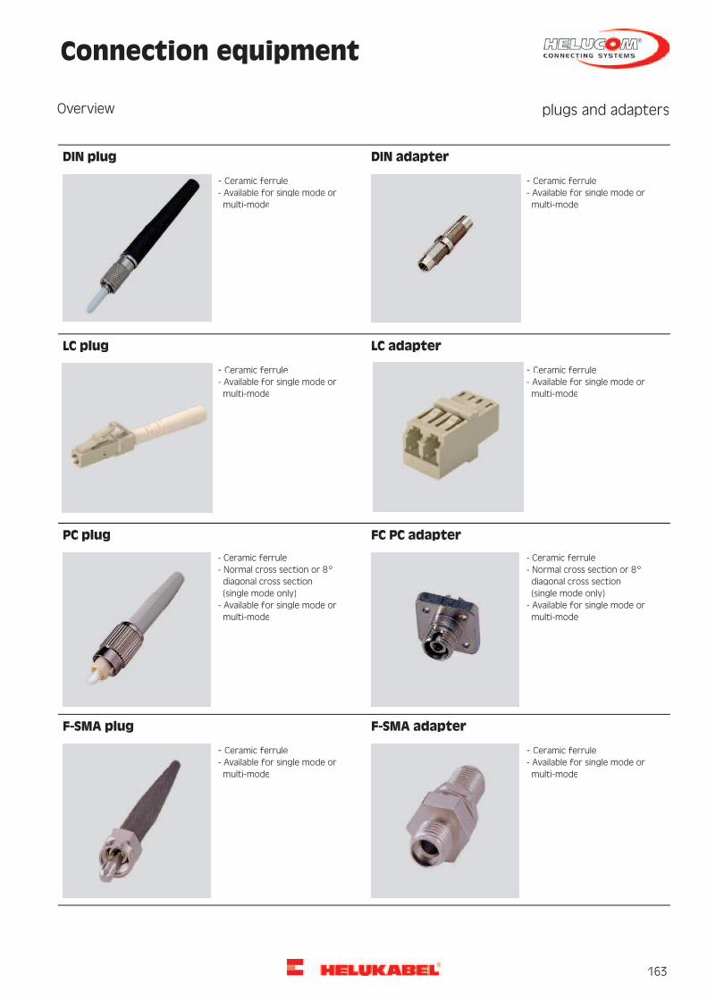
163
Connection equipment

164
Machine outlet IP67INDUSTRIAL ETHERNET
SC MM, IP67
Industrial Ethernet, SCdx multimode outlets IP67Type
ConfigurationAluminium die-castHousing material:GreyColour:StraightOutlet direction:ScrewType of fastening:Hinged coverDust protection:67Protection classification (IP):
CouplerEquipmentSCType:2Number of couplings:Multi-modeSuitable for fibre type:
175 x 110 x 45mmDimension
Industrial environmentArea of application
801354Part no.Dimensions and specifications may be changed without prior notice.
5Packing unit
HELUCOM CONNECTING SYSTEMS® INDUSTRY component suitable for multimode fibreapplications (G50/125μm and G62.5/125μm). Moreover it satisfies the MICE specifications
Norms and standards
(class 3), EMC requirements in accordance with DIN EN 6100, and the requirements of theIP 67 housing protection class.
Robust data connection socket (shielded) for the extreme implementation. Robust aluminumdie-cast housing; meets all mechanical requirements like vibration, shock, and transverse
Application
forces. The socket is used either on the machine distributor (MD) or wall mounted directlyon the machine (MC) as connection unit.

165
Machine outlet IP65INDUSTRIAL ETHERNET
SC MM, IP65
Industrial Ethernet outlet plastic IP 65, SCdxPOF/HCS/MM
Type
ConfigurationAluminium die-castHousing material:Grey similar to RAL 7032Colour:StraightOutlet direction:ScrewType of fastening:Hinged coverDust protection:65Protection classification (IP):
CouplerEquipmentSCType:2Number of couplings:POF/HCS/MMSuitable for fibre type:
125 x 80 x 57mmDimension
Industrial environmentArea of application
801421Part no.Dimensions and specifications may be changed without prior notice.
5Packing unit
HELUCOM CONNECTING SYSTEMS® INDUSTRY component suitable for POF, HCS and multimodefibre applications (980/1000μm, 200/230μm, 50/125μm and 62.5/125μm). More they satisfy
Norms and standards
the MICE specifications, EMC requirements in accordance with DIN EN 61000, and the IP65housing protection class requirements. The socket can be used in a temperature range of0°C to +70°C.
Robust data connection socket (shielded) for extreme implementation. Robust plastichousing, and satisfies all mechanical requirements like vibration, shock, and transverse
Application
forces. The socket is used either on the machine distributor (MD) or wall mounted directlyon the machine (MC) as connection unit.

166
Industrial EthernetPROFInet Type C
Torsion
Torsional applicationsType2x2x0,75 mm (stranded)Cable structureCopper, tinned (AWG 22/19)Inner conductor diameter:Foam-skin-PECore insulation:wh, ye, bu, ogCore colours:Star quadStranding element:Polyester foil over stranded bundleShielding 1:Polyester foil, aluminium-linedShielding 2:Cu braid, tinnedTotal shielding:PUROuter sheath material:approx. 6,5 mm ± 0,2 mmCable external diameter:Green similar to RAL 6018Outer sheath colour:
Electrical data100 Ohm ± 15 ohm at 1 to 100 MHzCharacteristic impedance:60 Ohm/kmConductor resistance, max.:0,5 GOhm x kmInsulation resistance, min.:120 Ohm/km max.Loop resistance:52 nF/km nom.Mutual capacitance:0,7 kVTest voltage:
Typical values10062,51610(MHz)Frequency41,026,510,07,6(db/100m)Attenuation20,024,039,743,8(db)ELFEXT
Technical dataapprox. 54 kg/kmWeight:70 mmbending radius, repeated:-40°COperating temperature range min.:+80°COperating temperature range max.:0,45 MJ/mCaloric load, approx. value:32,00 kg/kmCopper weight:
NormsPROFInet GuidelineApplicable standards:Category 5eHalogen-free acc. to 60754-2Flame-retardant acc. to IEC 60332-1Corrosiveness acc. to EN50267-2-3Low-smoke acc. to EN50268-2AWM Style 21161 80°CUL Style:
ApplicationThis copper data cable, designed especially for heavy-duty industrial applications is very well suited for Ethernet applications. Ir ensuressuperiour transmission properties and can be used even under most severe conditions. The lines specified here corresponds the PROFInettypes C, i.e. they are designed for torsion applications, such as roboter arms.
802186, PROFInet type C (SK)Part no.Dimensions and specifications may be changed without prior notice.

167
100TIndustrial EthernetTORDIERFLEX
SF/UTP, Category 5
Torsion Patch CablesTypeSF/UTP 4x2xAWG 26/19 PUR (stranded)Cable structureCopper, bare (AWG 26/19)Inner conductor diameter:PPCore insulation:wh/bu, wh/og, wh/gn, wh/bnCore colours:Double coreStranding element:Polyester foil over stranded bundleShielding 1:-Shielding 2:Polyester foil copper, bareScreen 1 over stranding:Cu braidScreen 2 over stranding:PUROuter sheath material:approx. 7,5 mmCable external diameter:Green similar to RAL 6018Outer sheath colour:
Electrical data100 Ohm ± 15 ohm at 1 to 100 MHzCharacteristic impedance:260 Ohm/km max.Loop resistance:50 nF/km nom.Mutual capacitance:68 %Relative propagation velocity:
Typical values10062,51610(MHz)Frequency4,03,21,61,3(dB/10m)Attenuation32,035,044,047,0(db)Next28,031,842,445,7(db)ACR
Technical dataapprox. 63 kg/kmWeight:80 mmbending radius, repeated:-40°COperating temperature range min.:+80°COperating temperature range max.:1,234 MJ/mCaloric load, approx. value:29,50 kg/kmCopper weight:
NormsAcc. to ISO/IEC 11801, Acc. to EN 50173, Acc. to EIA/TIA 568-A, Category 5, Flame-retardant acc. to IEC 60332-1, Smoke density acc. toIEC 61034, Halogen-free acc. to 60754-2, Oil-resistant, AWM 20963 (80°C/30V)
ApplicationHELUKAT®100T TORDIERFLEX data cables were designed for the most extreme requirements in the industry and other heavy-duty environmentsin torsion applications. They are characterized by large performance reserves and outstanding performance, even under extreme conditions.Long mechanical service life is also ensured due to a thought-out design. These lines are manufacturable with conventional Sub-D plugs orwith various RJ45 plugs.
800067, SF/UTP 4x2xAWG 26/19 PUR (S-FTP)Part no.Dimensions and specifications may be changed without prior notice.
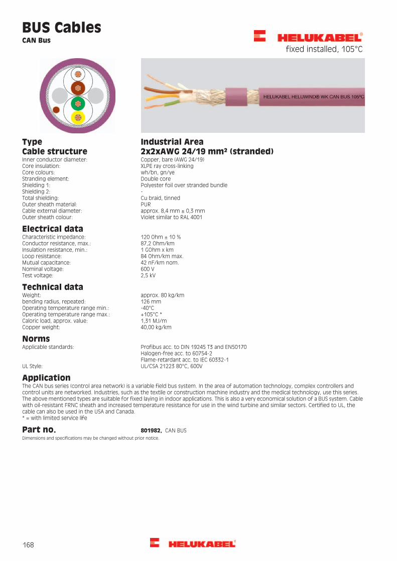
168
BUS CablesCAN Bus
fixed installed, 105°C
Industrial AreaType2x2xAWG 24/19 mm² (stranded)Cable structureCopper, bare (AWG 24/19)Inner conductor diameter:XLPE ray cross-linkingCore insulation:wh/bn, gn/yeCore colours:Double coreStranding element:Polyester foil over stranded bundleShielding 1:-Shielding 2:Cu braid, tinnedTotal shielding:PUROuter sheath material:approx. 8,4 mm ± 0,3 mmCable external diameter:Violet similar to RAL 4001Outer sheath colour:
Electrical data120 Ohm ± 10 %Characteristic impedance:87,2 Ohm/kmConductor resistance, max.:1 GOhm x kmInsulation resistance, min.:84 Ohm/km max.Loop resistance:42 nF/km nom.Mutual capacitance:600 VNominal voltage:2,5 kVTest voltage:
Technical dataapprox. 80 kg/kmWeight:126 mmbending radius, repeated:-40°COperating temperature range min.:+105°C *Operating temperature range max.:1,31 MJ/mCaloric load, approx. value:40,00 kg/kmCopper weight:
NormsProfibus acc. to DIN 19245 T3 and EN50170Applicable standards:Halogen-free acc. to 60754-2Flame-retardant acc. to IEC 60332-1UL/CSA 21223 80°C, 600VUL Style:
ApplicationThe CAN bus series (control area network) is a variable field bus system. In the area of automation technology, complex controllers andcontrol units are networked. Industries, such as the textile or construction machine industry and the medical technology, use this series.The above mentioned types are suitable for fixed laying in indoor applications. This is also a very economical solution of a BUS system. Cablewith oil-resistant FRNC sheath and increased temperature resistance for use in the wind turbine and similar sectors. Certified to UL, thecable can also be used in the USA and Canada.* = with limited service life
801982, CAN BUSPart no.Dimensions and specifications may be changed without prior notice.

169
BUS CablesProfibus SK
Indoor + Outdoor
Fixed installation,outdoor
Fixed installation, indoorType
1x2x0.64 mm1x2x0.64 mmCable structureCopper, bare (AWG 22/1)Copper, bare (AWG 22/1)Inner conductor diameter:Foam-skin-PEFoam-skin-PECore insulation:rd, gnrd, gnCore colours:Double coreDouble coreStranding element:Polyester foil over stranded bundlePolyester foil over stranded bundleShielding 1:PEPVCInner sheath material:Polyester foil, aluminium-linedPolyester foil, aluminium-linedShielding 2:Cu braid, tinnedCu braid, tinnedTotal shielding:PEPVCOuter sheath material:approx. 8,0 mm ± 0,4 mmapprox. 8,0 mm ± 0,4 mmCable external diameter:Black similar to RAL 9005Violet similar to RAL 4001Outer sheath colour:
Electrical data150 Ohm ± 10 %150 Ohm ± 10 %Characteristic impedance:55 Ohm/km55 Ohm/kmConductor resistance, max.:1 GOhm x km1 GOhm x kmInsulation resistance, min.:110 Ohm/km max.110 Ohm/km max.Loop resistance:35 nF/km nom.35 nF/km nom.Mutual capacitance:1,5 kV1,5 kVTest voltage:
Attenuation: dB/km2,5<kHz9,6dB/km2,5<kHz9,6dB/km4,0<kHz38,4 dB/km4,0<kHz38,4
dB/km22,0<MHz4dB/km22,0<MHz4,0dB/km42,0<MHz16,0 dB/km42,0<MHz16
Technical dataapprox. 65 kg/kmapprox. 79 kg/kmWeight:120 mm120 mmbending radius, repeated:-20°C-40°COperating temperature range min.:+70°C+80°COperating temperature range max.:1,451 MJ/m1,068 MJ/mCaloric load, approx. value:24,00 kg/km24,00 kg/kmCopper weight:
NormsProfibus acc. to DIN 19245 T3 and EN50170Profibus acc. to DIN 19245 T3 and EN50170
Flame-retardant acc. to IEC 60332-3Applicable standards:
Halogen-free acc. to 60754-2-CMG 75°C or CL3 or AWM 21694 600VUL Style:-CSA FT 4CSA standard:
ApplicationThe application of these Profibus SK cables are in the cell and field area, just as for conventional types. The great advantage of this newsystem is the quick connection of the cable to the respective plugs. This type of processing also avoids errors. The above mentioned typesare suitable for indoor- or outdoor installation and are equipped with a special PVC or PE sheath.
81904, Profibus SK81903, Profibus SKPart no.Dimensions and specifications may be changed without prior notice.

170
BUS CablesProfibus L2
TORSION + FESTOON
Mobile useTorsional applicationsType1x2x0.65 mm (stranded)1x2x0.80 mm (stranded)Cable structureCopper, bare (AWG 24/19)Copper, bare (AWG 22/19)Inner conductor diameter:Cell PEFoam-skin-PECore insulation:rd, gnrd, gnCore colours:2 cores + 2 fillers stranded together2 cores + fillerStranding element:Polyester foil over stranded bundlePolyester foil over stranded bundleShielding 1:Polyester foil, aluminium-linedPolyester foil, aluminium-linedShielding 2:Cu braid, tinnedCu braid, tinnedTotal shielding:PVCPUROuter sheath material:approx. 8,0 mm ± 0,3 mmapprox. 8,0 mm ± 0,4 mmCable external diameter:Petrol similar to RAL 5018Violet similar to RAL 4001Outer sheath colour:
Electrical data150 Ohm ± 10 %150 Ohm ± 10 %Characteristic impedance:66,5 Ohm/km49 Ohm/kmConductor resistance, max.:1,6 GOhm x km1 GOhm x kmInsulation resistance, min.:133 Ohm/km max.98 Ohm/km max.Loop resistance:28 nF/km nom.29 nF/km nom.Mutual capacitance:2 kV3,6 kVTest voltage:81 %-Relative propagation velocity:
Attenuation: dB/km3,0kHz9,6dB/km3,0<kHz9,6dB/km5,0<kHz38,4 dB/km4,0kHz38,4dB/km25,0<MHz4 dB/km25,0MHz4dB/km51,0<MHz16 dB/km49,0MHz16
Technical dataapprox. 64 kg/kmapprox. 66 kg/kmWeight:70 mm100 mmbending radius, repeated:-40°C-25°COperating temperature range min.:+60°C+75°COperating temperature range max.:1,09 MJ/m0,89 MJ/mCaloric load, approx. value:23,00 kg/km32,00 kg/kmCopper weight:
NormsProfibus acc. to DIN 19245 T3 and EN50170Profibus acc. to DIN 19245 T3 and EN50170
Halogen-free acc. to 60754-2Applicable standards:
Flame-retardant acc. to EN 50265-2-1Flame-retardant acc. to IEC 60332-1
CMG 75°C or CL2 or AWM 20201 600VCMX 75°C (shielded)UL Style:CSA FT 4-CSA standard:
ApplicationThe series TORSION and FESTOON are used to interconnect Profibus BUS components. This BUS system is a very economical solution for thefield area. For the information exchange between different automation systems as well as for communication with the connected decentralizedfield units, serial field bus systems are used. The lines described here are designed torsionable or hanging movable construction. Areas suchas robot applications and/or garland suspension are easily realized.
800649, Profibus L2800109, Profibus L2Part no.Dimensions and specifications may be changed without prior notice.

171
BUS CablesProfibus SK
FRNC + Robust
Industrial AreaFixed installation, indoorType1x2x0.64 mm1x2x0.64 mmCable structureCopper, bare (AWG 22/1)Copper, bare (AWG 22/1)Inner conductor diameter:Foam-skin-PEFoam-skin-PECore insulation:rd, gnrd, gnCore colours:Double coreDouble coreStranding element:Polyester foil over stranded bundlePolyester foil over stranded bundleShielding 1:PEFRNCInner sheath material:Polyester foil, aluminium-linedPolyester foil, aluminium-linedShielding 2:Cu braid, tinnedCu braid, tinnedTotal shielding:PURFRNCOuter sheath material:approx. 8,0 mm ± 0,4 mmapprox. 8,0 mm ± 0,4 mmCable external diameter:Violet similar to RAL 4001Violet similar to RAL 4001Outer sheath colour:
Electrical data150 Ohm ± 10 %150 Ohm ± 10 %Characteristic impedance:55 Ohm/km55 Ohm/kmConductor resistance, max.:1 GOhm x km1 GOhm x kmInsulation resistance, min.:110 Ohm/km max.110 Ohm/km max.Loop resistance:35 nF/km nom.35 nF/km nom.Mutual capacitance:1,5 kV1,5 kVTest voltage:
Attenuation: dB/km2,5<kHz9,6dB/km2,5<kHz9,6dB/km4,0<kHz38,4 dB/km4,0<kHz38,4
dB/km22,0<MHz4dB/km22,0<MHz4dB/km42,0<MHz16 dB/km42,0<MHz16
Technical dataapprox. 71 kg/kmapprox. 73 kg/kmWeight:120 mm160 mmbending radius, repeated:-40°C-25°COperating temperature range min.:+70°C+70°COperating temperature range max.:1,574 MJ/m1,203 MJ/mCaloric load, approx. value:24,00 kg/km24,00 kg/kmCopper weight:
NormsProfibus acc. to DIN 19245 T3 and EN50170Profibus acc. to DIN 19245 T3 and EN50170
Halogen-free acc. to 60754-2Applicable standards:
Halogen-free acc. to 60754-2Flame-retardant acc. to IEC 60332-1Flame-retardant acc. to EN 50265-2-1AWM Style 20236 AWM I/II A/B 80°C 30V FT1CM 750C (shielded)UL Style:CSA FT1-CSA standard:
ApplicationThe application of these Profibus SK cables are in the cell and field area, just as for conventional types. The great advantage of this newsystem is the quick connection of the cable to the respective plugs. This type of processing also avoids errors. The types mentioned hereare suitable for indoor laying (special FRNC sheath) and heay industry laying (PUR sheath).
81905, Profibus SK81501, Profibus SKPart no.Dimensions and specifications may be changed without prior notice.

172
WKFibre Optic Cable flexibleWK robust PUR + PVC (UL/CSA)
AT-V(ZN)H(ZN)11Y, AT-V(ZN)Y(ZN)Y
Other dataTemperature rangeLaying, min.: -10°C
Cable structureCore type: Composite bufferedStrain relief elements: Aramide
Max. tensile force: 4800 NMax. transverse pressure: 200 N / cmLongitudinally water-tight acc. toIEC 60794-1-2-F5
Laying, max.: +50°COperating, min.: -40°COperating, max.: +90°C
Outer sheath colour: Black
UV-resistantResistant to hammer impact acc. toIEC 60794-1-2-E6Bending cycles acc. to IEC 60794-1-2-E6:9.000Oil-resistant
Part no.Weightkg / km
ULhalogen-free
Flameproof
Min. stat.bendingradiusmm
Innersheathmaterial
Outersheathmaterial
Outer Øapprox.mm
Fibre typeNumber offibres
Designation
803346125noyesyes100ULSZHPUR8,5Multimode G50/1254AT-V(ZN)H(ZN)11Y803348125yesnoyes130PVCPVC8,5Multimode G50/1254AT-V(ZN)Y(ZN)Y803347320noyesyes190ULSZHPUR12,4Multimode G50/12512AT-V(ZN)H(ZN)11Y803349320yesnoyes190PVCPVC12,4Multimode G50/12512AT-V(ZN)Y(ZN)Y
Dimensions and specifications may be changed without prior notice.
ApplicationThe HELUCOM ® WK range is set apart by its extreme rugged yet highly-flexible design. It is used wherever demanding environmentalconditions and extreme movements occur. The tight buffer structure enables the cable to be pre-assembled on site with ease. Applicationsare for example Windturbines, TV transmissions, mobile field applications, etc..

173
WKFibre Optic Cable flexibleWK - mobile
A-V(ZN)11Y
Other dataTemperature rangeLaying, min.: +5°C
Cable structureCore type: Tight bufferStrain relief elements: Kevlar
Max. tensile force: 650 NMax. transverse pressure: 40 N / cmLongitudinally water-tight acc. toIEC 60794-1-2-F5
Laying, max.: +50°COperating, min.: -30°COperating, max.: +70°C
Outer sheath colour: Orange
UV-resistantResistant to hammer impact acc. toIEC 60794-1-2-E6Bending cycles acc. to IEC 60794-1-2-E6:500.000Oil-resistant
Part no.Weightkg / km
ULhalogen-free
Flameproof
Min. stat.bendingradiusmm
Outersheathmaterial
Outer Øapprox.mm
Fibre typeNumber offibres
Designation
8038220noyesyes75PUR5,0Multimode G50/1252Fibre-optic cable8036320noyesyes75PUR5,0Multimode G62.5/1252Fibre-optic cable8053431noyesyes90PUR5,8Multimode G50/1254Fibre-optic cable8103631noyesyes90PUR5,8Multimode G62.5/1254Fibre-optic cable80172731noyesyes90PUR5,8Single-mode E9/1254Fibre-optic cable8103747noyesyes105PUR7,0Multimode G50/1258Fibre-optic cable8103847noyesyes105PUR7,0Multimode G62.5/1258Fibre-optic cable
Dimensions and specifications may be changed without prior notice.
ApplicationThese HELUCOM® cables were designed as mobile field cables. They are easily wound up on a drum and are very tension-proof. As the outersheath is tightly anchored on the aramid braiding, it is especially suitable for mobile use. The advantage of these cables is evident especiallywhere mobile fibre-optic lines are to be installed, such as for drag chains, TV transmission, supervision of protected areas, etc.

174
WKFibre Optic Cable flexibleWK - UL/CSA
A-V(ZN)YY
Other dataTemperature rangeLaying, min.: 0°C
Cable structureCore type: Tight bufferStrain relief elements: Aramide
Max. tensile force: 1200 NMax. transverse pressure: 44 N / cmLongitudinally water-tight acc. toIEC 60794-1-2-F5
Laying, max.: +50°COperating, min.: -30°COperating, max.: +80°C
Outer sheath colour: Orange
UV-resistantBending cycles acc. to IEC 60794-1-2-E6:9.000Oil-resistant
Part no.Weightkg / km
ULhalogen-free
Flameproof
Min. stat.bendingradiusmm
Innersheathmaterial
Outersheathmaterial
Outer Øapprox.mm
Fibre typeNumber offibres
Designation
80279250yesnoyes75PVCPVC7,0Multimode G50/1254Fibre-optic cable80393450yesnoyes75PVCPVC7,0Multimode G62.5/1254Fibre-optic cable80393550yesnoyes75PVCPVC7,0Single-mode E9/1254Fibre-optic cable
Dimensions and specifications may be changed without prior notice.
ApplicationThese HELUCOM® cables were designed as mobile field cables. They are easily wound up on a drum and are very tension-proof. As the outersheath is tightly anchored on the aramid braiding, it is especially suitable for mobile use. The advantage of these cables is evident especiallywhere mobile fibre-optic lines are to be installed, such as windturbine projects, TV transmission, supervision of protected areas, etc.. Thisseries with PVC jacket is certified according the UL/CSA standard OFNG/ FT4.

175
Fibre Optic Breakout Cable robust,flexibleHCS UL/CSA
I-V(ZN)YY
Other dataTemperature rangeLaying, min.: -20°C
Cable structureCore type: Composite bufferedStrain relief elements: Aramide
Flame-resistance acc. to IEC 60332-1 andIEC 60332-3UV-resistant
Laying, max.: +75°COperating, min.: -30°COperating, max.: +85°C
Outer sheath material: PVCOuter sheath colour: Black Oil-resistant
Part no.Weightkg / km
Caloric loadapprox.MJ / m
Max.transversepressureN / cm
Min. stat.bendingradiusmm
Max.tensileforce N
Outer Øapprox.mm
Number offibres percore
Fibre typeNumber offibres
Designation
80173368,01,40300100,08007,51HCS 200/2302I-V(ZN)YY
Dimensions and specifications may be changed without prior notice.
ApplicationThis HELUCOM® HCS fibre cable is suitable for fixed and normal flexible installations. Possible applications are normal and heavy-duty mechanicalrequirements for example in industrial environments. Because of a special PVC jacket this construction is certified by UL (FT1 and FT4). Withthe tight buffer construction, direct plug manufacturing, even on site, poses no problems. With a HCS fibre transmission lengths of up to300m can be achieved.

176
Fibre Optic Breakout Cable robustflexibleHCS
I-V(ZN)Y11Y
Other dataTemperature rangeLaying, min.: -5°C
Cable structureCore type: Composite bufferedStrain relief elements: Aramide
Oil-resistantLaying, max.: +50°COperating, min.: -20°COuter sheath material: PUR
Outer sheath colour: Red Operating, max.: +70°C
Part no.Weightkg / km
Caloric loadapprox.MJ / m
Max.transversepressureN / cm
Min. stat.bendingradiusmm
Max.tensileforce N
Outer Øapprox.mm
Number offibres percore
Fibre typeNumber offibres
Designation
80098043,01,01415050,08007,01HCS 200/2302I-V(ZN)Y11Y
Dimensions and specifications may be changed without prior notice.
ApplicationThis HELUCOM® HCS fibre cable is suitable for fixed installation. Possible applications are normal and heavy-duty mechanical requirementsfor example in industrial environments. With the tight buffer construction, direct plug manufacturing, even on site, poses no problems.With a HCS fibre transmission lengths of up to 300m can be achieved.
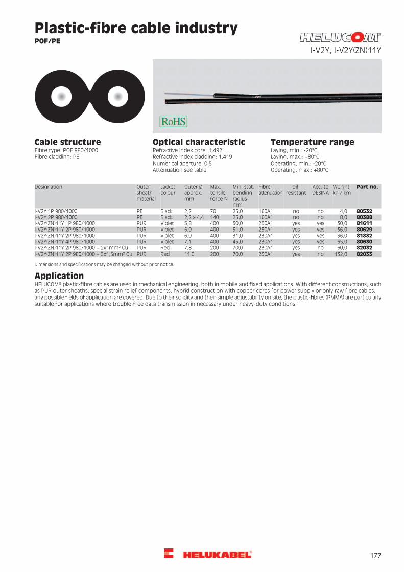
177
Plastic-fibre cable industryPOF/PE
I-V2Y, I-V2Y(ZN)11Y
Temperature rangeOptical characteristicRefractive index core: 1,492
Cable structureFibre type: POF 980/1000Fibre cladding: PE
Laying, min.: -20°CLaying, max.: +80°COperating, min.: -20°C
Refractive index cladding: 1,419Numerical aperture: 0,5Attenuation see table Operating, max.: +80°C
Part no.Weightkg / km
Acc. toDESINA
Oil-resistant
Fibreattenuation
Min. stat.bendingradiusmm
Max.tensileforce N
Outer Øapprox.mm
Jacketcolour
Outersheathmaterial
Designation
805324,0nono160A125,0702,2BlackPEI-V2Y 1P 980/1000803888,0nono160A125,01402,2 x 4,4BlackPEI-V2Y 2P 980/10008161130,0yesyes230A130,04005,8VioletPURI-V2Y(ZN)11Y 1P 980/10008062936,0yesyes230A131,04006,0VioletPURI-V2Y(ZN)11Y 2P 980/10008188236,0yesyes230A131,04006,0VioletPURI-V2Y(ZN)11Y 2P 980/10008063065,0yesyes230A145,04007,1VioletPURI-V2Y(ZN)11Y 4P 980/10008203260,0noyes230A170,02007,8RedPURI-V2Y(ZN)11Y 2P 980/1000 + 2x1mm² Cu82033132,0noyes230A170,020011,0RedPURI-V2Y(ZN)11Y 2P 980/1000 + 3x1,5mm² Cu
Dimensions and specifications may be changed without prior notice.
ApplicationHELUCOM® plastic-fibre cables are used in mechanical engineering, both in mobile and fixed applications. With different constructions, suchas PUR outer sheaths, special strain relief components, hybrid construction with copper cores for power supply or only raw fibre cables,any possible fields of application are covered. Due to their solidity and their simple adjustability on site, the plastic-fibres (PMMA) are particularlysuitable for applications where trouble-free data transmission in necessary under heavy-duty conditions.

178
Fibre Optic Indoor/Outdoor Cableacc. DIN VDE 0888
A/I-DQ(ZN)BH, central
Other dataTemperature rangeLaying, min.: -5°C
Cable structureCore type: Loose tubeStrain relief elements: Glass yarns
Corrosiveness acc. to EN50267-2-3Halogen-free acc. to 60754-2Flame-resistance acc. to IEC 60332-1
Laying, max.: +50°COperating, min.: -20°COperating, max.: +60°C
Type of armouring: Glass yarnsOuter sheath material: FRNCOuter sheath colour: Black
Smoke density acc. to IEC 61034Longitudinally water-tight acc. toIEC 60794-1-2-F5UV-resistant
Part no.Weightkg / km
Max.transversepressureN / cm
Caloric loadapprox.MJ / m
Min. stat.bendingradiusmm
Max.tensileforce N
Outer Øapprox.mm
Number offibres percore
Fibre categoryFibre typeNo. offibres
Designation
8027075,03001,50150,0250010,04OM2Multimode G50/1254A/I-DQ(ZN)BH8027675,03001,50150,0250010,04OM1Multimode G62.5/1254A/I-DQ(ZN)BH8026475,03001,50150,0250010,04ITU-T G.652Single-mode E9/1254A/I-DQ(ZN)BH8027175,03001,50150,0250010,06OM2Multimode G50/1256A/I-DQ(ZN)BH8026575,03001,50150,0250010,06OM1Multimode G62.5/1256A/I-DQ(ZN)BH8027275,03001,50150,0250010,06ITU-T G.652Single-mode E9/1256A/I-DQ(ZN)BH8027375,03001,50150,0250010,08OM2Multimode G50/1258A/I-DQ(ZN)BH8027475,03001,50150,0250010,08OM1Multimode G62.5/1258A/I-DQ(ZN)BH8027575,03001,50150,0250010,08ITU-T G.652Single-mode E9/1258A/I-DQ(ZN)BH8068175,03001,50150,0250010,012OM2Multimode G50/12512A/I-DQ(ZN)BH8027875,03001,50150,0250010,012OM1Multimode G62.5/12512A/I-DQ(ZN)BH8027975,03001,50150,0250010,012ITU-T G.652Single-mode E9/12512A/I-DQ(ZN)BH8028085,03001,50150,0250010,016OM2Multimode G50/12516A/I-DQ(ZN)BH8028185,03001,50150,0250010,016OM1Multimode G62.5/12516A/I-DQ(ZN)BH8085185,03001,50150,0250010,016ITU-T G.652Single-mode E9/12516A/I-DQ(ZN)BH8072585,03001,50150,0250010,024OM2Multimode G50/12524A/I-DQ(ZN)BH8243185,03001,50150,0250010,024OM1Multimode G62.5/12524A/I-DQ(ZN)BH
Dimensions and specifications may be changed without prior notice.
ApplicationThese HELUCOM® fibre-optic cables are available either as central bundle core cable or as stranded versions. They are suitable for indoor andoutdoor cabling of buildings and facilities. They are used in particular if the installation is to be done in one piece from the inside to theoutside without additional use of couplings. With their black UV-resistant outer sheath and the non-metallic rodent protection, they areperfectly suited for outdoor use. The halogen-free outer sheath makes installation inhouse possible without any problems.

179
pactFibre Optic Outdoor Cableacc. DIN VDE 0888
A-DQ(ZN)B2Y, central
Other dataTemperature rangeLaying, min.: -5°C
Cable structureCore type: Loose tubeStrain relief elements: Glass yarns
Corrosiveness acc. to EN50267-2-3Halogen-free acc. to 60754-2Longitudinally water-tight acc. toIEC 60794-1-2-F5
Laying, max.: +50°COperating, min.: -20°COperating, max.: +60°C
Type of armouring: Glass yarnsOuter sheath material: PEOuter sheath colour: Black UV-resistant
Part no.Weightkg / km
Max.transversepressureN / cm
Caloric loadapprox.MJ / m
Min. stat.bendingradiusmm
Max.tensileforce N
Outer Øapprox.mm
Number offibres percore
Fibre categoryFibre typeNo. offibres
Designation
80075440,03001,60150,015007,52OM2Multimode G50/1252A-DQ(ZN)B2Y80213140,03001,60150,015007,52OM1Multimode G62.5/1252A-DQ(ZN)B2Y80213740,03001,60150,015007,52ITU-T G.652Single-mode E9/1252A-DQ(ZN)B2Y80075540,03001,60150,015007,54OM2Multimode G50/1254A-DQ(ZN)B2Y80213240,03001,60150,015007,54OM1Multimode G62.5/1254A-DQ(ZN)B2Y80213840,03001,60150,015007,54ITU-T G.652Single-mode E9/1254A-DQ(ZN)B2Y80075640,03001,60150,015007,56OM2Multimode G50/1256A-DQ(ZN)B2Y80213340,03001,60150,015007,56OM1Multimode G62.5/1256A-DQ(ZN)B2Y80213940,03001,60150,015007,56ITU-T G.652Single-mode E9/1256A-DQ(ZN)B2Y80075740,03001,60150,015007,58OM2Multimode G50/1258A-DQ(ZN)B2Y80213440,03001,60150,015007,58OM1Multimode G62.5/1258A-DQ(ZN)B2Y80214040,03001,60150,015007,58ITU-T G.652Single-mode E9/1258A-DQ(ZN)B2Y80075940,03001,60150,015007,512OM2Multimode G50/12512A-DQ(ZN)B2Y80213540,03001,60150,015007,512OM1Multimode G62.5/12512A-DQ(ZN)B2Y80214140,03001,60150,015007,512ITU-T G.652Single-mode E9/12512A-DQ(ZN)B2Y80214260,03001,90170,015008,524ITU-T G.652Single-mode E9/12524A-DQ(ZN)B2Y80076260,03001,90170,015008,524OM2Multimode G50/12524A-DQ(ZN)B2Y80213660,03001,90170,015008,524OM1Multimode G62.5/12524A-DQ(ZN)B2Y
Dimensions and specifications may be changed without prior notice.
ApplicationThese HELUCOM® pact fibre-optic cables are characterized by a design that is particularly easy to mount and is rodent-protected. Around acentral grooved cable, there is a composite of glass yarns and swelling fleece with characteristics that ensure rodent protection, strain relief,and waterproofing in longitudinal direction of the cable. In addition, these cables are designed grease-free. Wiping the jelly off is thereforeunnecessary. This construction is particularly used in underground, tubes and channel areas, where normal tensile stresses and/or transversecompressions occur and rodent infestation is to be expected.

180
Fibre Optic Outdoor Cableacc. DIN VDE 0888
A-DQ(ZN)B2Y, central
Other dataTemperature rangeLaying, min.: -5°C
Cable structureCore type: Loose tubeStrain relief elements: Glass yarns
Corrosiveness acc. to EN50267-2-3Halogen-free acc. to 60754-2Longitudinally water-tight acc. toIEC 60794-1-2-F5
Laying, max.: +50°COperating, min.: -20°COperating, max.: +60°C
Type of armouring: Glass yarnsOuter sheath material: PEOuter sheath colour: Black UV-resistant
Part no.Weightkg / km
Max.transversepressureN / cm
Caloric loadapprox.MJ / m
Min. stat.bendingradiusmm
Max.tensileforce N
Outer Øapprox.mm
Number offibres percore
Fibre categoryFibre typeNo. offibres
Designation
8019685,03001,60160,0250010,02OM2Multimode G50/1252A-DQ(ZN)B2Y8021285,03001,60160,0250010,02OM1Multimode G62.5/1252A-DQ(ZN)B2Y8018085,03001,60160,0250010,02ITU-T G.652Single-mode E9/1252A-DQ(ZN)B2Y8019785,03001,60160,0250010,04OM2Multimode G50/1254A-DQ(ZN)B2Y8021385,03001,60160,0250010,04OM1Multimode G62.5/1254A-DQ(ZN)B2Y8018185,03001,60160,0250010,04ITU-T G.652Single-mode E9/1254A-DQ(ZN)B2Y8019885,03001,60160,0250010,06OM2Multimode G50/1256A-DQ(ZN)B2Y8021485,03001,60160,0250010,06OM1Multimode G62.5/1256A-DQ(ZN)B2Y8018285,03001,60160,0250010,06ITU-T G.652Single-mode E9/1256A-DQ(ZN)B2Y8019985,03001,60160,0250010,08OM2Multimode G50/1258A-DQ(ZN)B2Y8021585,03001,60160,0250010,08OM1Multimode G62.5/1258A-DQ(ZN)B2Y8018385,03001,60160,0250010,08ITU-T G.652Single-mode E9/1258A-DQ(ZN)B2Y8020185,03001,60160,0250010,012OM2Multimode G50/12512A-DQ(ZN)B2Y8021785,03001,60160,0250010,012OM1Multimode G62.5/12512A-DQ(ZN)B2Y8018585,03001,60160,0250010,012ITU-T G.652Single-mode E9/12512A-DQ(ZN)B2Y8020295,03001,80180,0250010,016OM2Multimode G50/12516A-DQ(ZN)B2Y8021895,03001,80180,0250010,016OM1Multimode G62.5/12516A-DQ(ZN)B2Y8018695,03001,80180,0250010,016ITU-T G.652Single-mode E9/12516A-DQ(ZN)B2Y8020495,03001,80180,0250010,024OM2Multimode G50/12524A-DQ(ZN)B2Y8022095,03001,80180,0250010,024OM1Multimode G62.5/12524A-DQ(ZN)B2Y8018795,03001,80180,0250010,024ITU-T G.652Single-mode E9/12524A-DQ(ZN)B2Y
Dimensions and specifications may be changed without prior notice.
ApplicationThese HELUCOM® fibre-optic cables are characterized by a design that is particularly easy to mount and is rodent-protected. Around a centralgrooved cable, there is a composite of glass yarns and swelling fleece with characteristics that ensure rodent protection, strain relief, andwaterproofing in longitudinal direction of the cable. In addition, these cables are designed grease-free. Wiping the jelly off is thereforeunnecessary. This construction is particularly used in underground, tubes and channel areas, where normal tensile stresses and/or transversecompressions occur and rodent infestation is to be expected.

181
Fibre Optic Outdoor Cableacc. DIN VDE 0888
A-DQ(ZN)B2Y, stranded
Other dataTemperature rangeLaying, min.: -5°C
Cable structureCore type: Loose tubeGRP support element
Corrosiveness acc. to EN50267-2-3Halogen-free acc. to 60754-2Longitudinally water-tight acc. toIEC 60794-1-2-F5
Laying, max.: +50°COperating, min.: -20°COperating, max.: +60°C
Strain relief elements: Glass yarnsType of armouring: Glass yarnsOuter sheath material: PE UV-resistantOuter sheath colour: Black
Part no.Weightkg / km
Max.transversepressureN / cm
Caloric loadapprox.MJ / m
Min. stat.bendingradiusmm
Max.tensileforce N
Outer Øapprox.mm
Number offibres percore
Fibre categoryFibre typeNo. offibres
Designation
8138295,06002,70210,0270010,512OM2Multimode G50/12524A-DQ(ZN)B2Y8021995,06002,70210,0270010,512OM1Multimode G62.5/12524A-DQ(ZN)B2Y8018895,06002,70210,0270010,512ITU-T G.652Single-mode E9/12524A-DQ(ZN)B2Y8110895,06002,70210,0270010,512OM2Multimode G50/12536A-DQ(ZN)B2Y8110995,06002,70210,0270010,512OM1Multimode G62.5/12536A-DQ(ZN)B2Y8111095,06002,70210,0270010,512ITU-T G.652Single-mode E9/12536A-DQ(ZN)B2Y8264895,06002,70210,0270010,512OM2Multimode G50/12548A-DQ(ZN)B2Y8111295,06002,70210,0270010,512OM1Multimode G62.5/12548A-DQ(ZN)B2Y8111395,06002,70210,0270010,512ITU-T G.652Single-mode E9/12548A-DQ(ZN)B2Y8020795,06002,70210,0270010,512OM2Multimode G50/12560A-DQ(ZN)B2Y8022395,06002,70210,0270010,512OM1Multimode G62.5/12560A-DQ(ZN)B2Y8019195,06002,70210,0270010,512ITU-T G.652Single-mode E9/12560A-DQ(ZN)B2Y81133100,06002,90220,0270011,012OM2Multimode G50/12572A-DQ(ZN)B2Y81134100,06002,90220,0270011,012OM1Multimode G62.5/12572A-DQ(ZN)B2Y81120100,06002,90220,0270011,012ITU-T G.652Single-mode E9/12572A-DQ(ZN)B2Y80208140,06003,60240,0300012,012OM2Multimode G50/12584A-DQ(ZN)B2Y80224140,06003,60240,0300012,012OM1Multimode G62.5/12584A-DQ(ZN)B2Y80192140,06003,60240,0300012,012ITU-T G.652Single-mode E9/12584A-DQ(ZN)B2Y81135140,06003,60240,0300012,012OM2Multimode G50/12596A-DQ(ZN)B2Y81136140,06003,60240,0300012,012OM1Multimode G62.5/12596A-DQ(ZN)B2Y81121140,06003,60240,0300012,012ITU-T G.652Single-mode E9/12596A-DQ(ZN)B2Y80209155,06004,30270,0300013,512OM2Multimode G50/125108A-DQ(ZN)B2Y80225155,06004,30270,0300013,512OM1Multimode G62.5/125108A-DQ(ZN)B2Y80193155,06004,30270,0300013,512ITU-T G.652Single-mode E9/125108A-DQ(ZN)B2Y80210155,06004,30270,0300013,512OM2Multimode G50/125120A-DQ(ZN)B2Y80226155,06004,30270,0300013,512OM1Multimode G62.5/125120A-DQ(ZN)B2Y80194155,06004,30270,0300013,512ITU-T G.652Single-mode E9/125120A-DQ(ZN)B2Y80211200,06005,40290,0300014,512OM2Multimode G50/125144A-DQ(ZN)B2Y80227200,06005,40290,0300014,512OM1Multimode G62.5/125144A-DQ(ZN)B2Y80195200,06005,40290,0300014,512ITU-T G.652Single-mode E9/125144A-DQ(ZN)B2Y
Dimensions and specifications may be changed without prior notice.
ApplicationThese HELUCOM® fibre-optic cables are characterized by a design that is particularly easy to mount, extremely tension-resistant androdent-proof. Around a stranded grooved cable and filler elements, there is a composite of glass yarns and swelling fleece with characteristicsthat ensure rodent protection, strain relief, and waterproofing in longitudinal direction of the cable. In addition, these cables are designedgrease-free. Wiping the jelly off is therefore unnecessary. This construction is particularly used in underground, tubes and channel areas,where above-average tensile stresses and/or transverse compressions occur and rodent infestation is to be expected.

182
pactFibre Optic Outdoor Cableacc. DIN VDE 0888
A-DQ(ZN)B2Y fibre combi, stranded
Other dataTemperature rangeLaying, min.: -5°C
Cable structureCore type: Loose tubeGRP support element
Corrosiveness acc. to EN50267-2-3Longitudinally water-tight acc. toIEC 60794-1-2-F5
Laying, max.: +50°COperating, min.: -20°COperating, max.: +60°C
Strain relief elements: Glass yarnsType of armouring: Glass yarnsOuter sheath material: PE
UV-resistant
Outer sheath colour: Black
Part no.Weightkg / km
Max.transversepressureN / cm
Caloric loadapprox.MJ / m
Min. stat.bendingradiusmm
Max.tensileforce N
Outer Øapprox.mm
Number offibres percore
Fibre categoryFibre typeNo. offibres
Designation
80303790,04002,50200,025009,512OM2 + ITU-TG.652
Single- and multimodeG50/125
24A-DQ(ZN)B2Y
80392390,04002,50200,025009,512OM3 + ITU-TG.652
Single- und MultimodeG50/125 OM3
24A-DQ(ZN)B2Y
80303890,04002,50200,025009,512OM2 + ITU-TG.652
Single- and multimodeG50/125
48A-DQ(ZN)B2Y
80392490,04002,50200,025009,512OM3 + ITU-TG.652
Single- und MultimodeG50/125 OM3
48A-DQ(ZN)B2Y
Dimensions and specifications may be changed without prior notice.
ApplicationThese HELUCOM® pact fibre-optic cables are characterized by a design that is particularly easy to mount, tension-resistant and rodent-proof.Around a stranded grooved cable and filler elements, there is a composite of glass yarns and swelling fleece with characteristics that ensurerodent protection, strain relief and waterproofing in longitudinal direction of the cable. In addition, these cables are designed grease-free.Wiping the jelly off is therefore unnecessary. This construction is particularly used in underground, tubes and channel areas, where packingdensity also plays a role.

183
Cable accessories for wind power plants
As a practical supplement to the extensive assortment of cables and lines; HELUKABEL® has established a cable accessory program corresponding to the most current guidelines and standards; it is impressive.
The following topics are included in this:
The newHELUKABEL® accessory catalog.
Now request it free at www.helukabel.com
CABLE ACCESSORIES

184
Material:galvanized stranded wire
Application Employed as a cable installation grip. For anti-slip installation of vertically attached cables.
Material:galvanized stranded wire
Application This cable grip is used wherever cables with high tensile forces are routed.
Properties:
Properties:
Dimensions and specifications may be changed without prior notice. Prices on request.
Dimensions and specifications may be changed without prior notice. Prices on request.
Cable installation grips with side loop
Cable grips with thimble and press clamp
Cable conduit with inner striationsSuitable for plowing-in, laying in trenches, for blowing-in and pulling-in fiber optic cable, outside diameter 32 to 50 mm.
Part no.
Min. interior diameter mm
Max. interior diameter mm
Length mm
Loadability in kN
Weigth kg
905909 8 10 500 2,2 0,07905601 10 15 500 3,4 0,08905602 15 20 500 4,3 0,14905603 20 25 500 6,8 0,16905604 25 30 500 8,1 0,18905597 30 40 500 11,7 0,4905605 40 50 800 16,0 0,45905606 50 60 800 16,0 0,6905607 60 70 800 21,0 0,7905918 70 90 800 21,0 0,9905919 90 110 800 26,7 1,2
Cable installation grips with side loop, laterally displaced, open
Cable grips with thimble and press clamp, closedPart no.
Min. interior diameter mm
Max. interior diameter mm
Length mm
Loadability in kN
Weigth kg
905891 6 10 600 2,2 0,07905892 10 15 600 3,4 0,08905893 15 20 600 6,8 0,14905375 20 25 600 6,8 0,15905371 25 30 1000 8,1 0,18905376 30 40 1250 11,7 0,4905894 40 50 1250 16,0 0,45905163 50 60 1500 16,0 0,6905895 60 70 1500 21,3 0,7905896 70 90 1500 27,9 0,9905897 90 110 1500 34,9 1,5

185
Technical Data: Protection classification: IP 68 - 5 barTemperature range: -30°C up to +80°CTesting standard: EN50262
Technical Data: Protection classification: IP 68 - 5 barTemperature range: -40°C up to +100°CTesting standard: EN50262
Technical Data: Protection classification: IP68 – 5barTemperature range: -40°C bis +100°CTesting standard: EN 50262
Cable gland – HELUTOP®
Properties:
Properties:
Properties:
rotating spring ring
beryllium springs
from clamping to contact range
Properties:
HELUTOP® HT
HELUTOP® HT-MS
HELUTOP® MS-EP4
HELUTOP® HT-E
The plastic cable gland with vibration protection.
The cable gland made of nickel-plated brass.
The new generation of EMC and earth glands with integrated contact system for reliable, quick assembly and contacting.
The stainless steel cable gland for use in high-stress applications.
Material:
Shell: polyamide PA 6Moulded seal: Neoprene
Material: Shell: brass, nickel-platedTerminal insert: polyamide PA 6Moulded seal: NeopreneO-ring: Buna-N
Material: Shell: brass, nickel-platedContact spring: Copper-berylliumTerminal insert: polyamide PA 6Gasket: NeopreneO-ring: NBR
Material: stainless steel 1.4305Terminal insert: polyamide PA 6Moulded seal: NeopreneO-ring: Buna-N
Technical Data: Protection classification: IP 68 - 5 barTemperature range: -40°C up to +100°CTesting standard: EN50262

186
Technical Data Material: CU-HCP according to DIN EN 13600Surface: tin plated
WK-CU compression cable lugPart No.
Cross section mm2
Hole M
Key figures
Dimension in mm Weight 100 pcs. approx. kg
VPEpcs.
d1 d3 d2 b l a
906524 95 10 18 13,5 19,0 10,5 28,0 65,5 35,0 9,55 50906525 95 12 18 13,5 19,0 13,0 28,0 65,5 35,0 9,45 50906526 120 10 20 15,5 21,0 10,5 31,0 70,0 35,0 11,40 50906527 120 12 20 15,5 21,0 13,0 31,0 70,5 35,0 11,44 50906528 150 12 22 17,0 23,5 13,0 34,0 78,5 35,0 16,76 25906529 150 16 22 17,0 23,5 17,0 34,0 78,0 35,0 16,35 25906530 185 12 25 19,0 25,5 13,0 37,0 82,5 40,0 18,95 25906531 185 16 25 19,0 25,5 17,0 37,0 82,0 40,0 18,78 25906532 240 12 28 21,5 29,0 13,0 42,5 92,0 40,0 27,08 20906533 240 16 28 21,5 29,0 17,0 42,5 92,0 40,0 27,45 20906534 300 16 32 24,5 32,0 17,0 48,5 100,0 50,0 33,72 10906535 300 20 32 24,5 32,0 21,0 48,5 100,0 50,0 34,37 10906536 400 16 38 27,5 38,5 17,0 55,0 117,0 70,0 70,28 5906537 400 20 38 27,5 38,5 21,0 55,0 117,0 70,0 70,60 5906538 500 20 42 31,0 42,0 21,0 60,0 130,0 70,0 87,66 5
Other dimensions available on request. Subject to technical changes. Prices available on request.
WK-CU compression cable lug DIN 46235, straight ring design

187
Technical Data Material: Aluminium AL 99.5Surface: bright
Instructions
WK-AL compression cable lugPart No.
Cross section mm2
Hole M
for *ALU Powerllne(Conductor category 5)
Key figures
Dimension in mm Weight 100 pcs. approx. kg
VPEpcs.
rm/sm* se** d1 d3 d2 b l a
906459 150 185 10 150 25 16,5 25 10,5 35 104 64 10,00 10906436 150 185 12 150 25 16,5 25 13 35 104 64 10,03 10906461 150 185 16 150 25 16,5 25 17 35 104 64 10,08 10906462 150 185 20 150 25 16,5 25 21 35 104 64 10,02 10906463 185 240 12 28 18,5 28,5 13 40 109 66 13,39 10906464 185 240 16 28 18,5 28,5 17 40 109 66 13,75 10906465 185 240 20 28 18,5 28,5 21 40 109 66 13,76 10906466 240 300 12 185 32 21,3 32 13 46 119 70 17,58 10906467 240 300 16 185 32 21,3 32 17 46 119 70 17,62 10906468 240 300 20 185 32 21,3 32 21 46 119 70 17,90 10906469 300 - 12 240 34 23,3 34 13 50 125 70 18,00 5906470 300 - 16 240 34 23,3 34 17 50 125 70 22,10 5906471 300 - 20 240 34 23,3 34 21 50 125 70 19,43 5906472 400 - 12 300 38 26 38,5 13 55 120 70 24,40 5906473 400 - 16 300 38 26 38,5 17 55 120 70 24,40 5906474 400 - 20 300 38 26 38,5 21 55 120 70 24,00 5906475 500 - 12 400 44 29 44 13 63 140 80 38,00 5906476 500 - 16 400 44 29 44 17 63 140 80 37,80 5906477 500 - 20 400 44 29 44 21 63 140 80 37,35 5
Other dimensions available on request. Subject to technical changes. Prices available on request.
WK-AL compression cable lug straight ring design
KAC-U washers

188
Technical Data Material: Aluminum AL 99.5Surface: bright or tinned
Instructions
WK-AL compression cable lug FG extrudedPart No.bright
Part No.tinned
Cross sectionmm2 rm/sm*
Hole M
for *ALU Powerllne(Conductor category 5)
Key figures
Dimension in mm
d1 d3 d2 b l a
906539 906562 95 10 95 22 13,2 22 10,5 25 75 56906540 906563 95 12 95 22 13,2 22 13 25 75 56906541 906564 120 10 120 22 14,7 14,7 10,5 30 80 56906542 906565 120 12 120 22 14,7 14,7 13 30 80 56906543 906566 120 16 120 22 14,7 14,7 17 30 80 56906544 906567 150 10 150 25 16,3 25 10,5 30 90 60906545 906568 150 12 150 25 16,3 25 13 30 90 60906546 906569 150 16 150 25 16,3 25 17 30 90 60906547 906570 185 10 28 18,3 28,5 10,5 30 91 60906548 906571 185 12 28 18,3 28,5 13 30 91 60906549 906572 185 16 28 18,3 28,5 17 30 91 60906550 906573 240 12 185 32 21 32 13 38 103 70906551 906574 240 16 185 32 21 32 17 38 103 70906552 906575 240 20 185 32 21 32 21 38 103 70906553 906576 300 12 240 34 23,3 34 13 38 103 70906554 906577 300 16 240 34 23,3 34 17 38 103 70906555 906578 300 20 240 34 23,3 34 21 38 103 70906556 906579 400 12 300 38 26 38,5 13 38 116 73906557 906580 400 16 300 38 26 38,5 17 38 116 73906558 906581 400 20 300 38 26 38,5 21 38 116 73906559 906582 500 12 400 44 29 44 13 44 122 79906560 906583 500 16 400 44 29 44 17 44 122 79906561 906584 500 20 400 44 29 44 21 44 122 79
Other dimensions available on request. Subject to technical changes. Prices available on request.
WK-AL compression cable lug FG extrudedstraight ring design

189
Technical Data Material: Aluminum AL 99.5 CU-ETP according to DIN EN 13601Surface: bright
Instructions
WK-AL/CU compression cable lugsPart No.
Cross section mm2
Hole M
for *ALU Powerllne(Conductor category 5)
Key figures K
Dimension in mm Weight 100 pcs. approx. kg
VPEpcs.
rm/sm* se** d1 d3 d2 b l Total Cu
906478 150 185 10 150 25 16,3 25 10,5 30 100 13,80 8,31 5906172 150 185 12 150 25 16,3 25,5 13 30 100 13,57 8,07 5906173 150 185 16 150 25 16,3 25,5 17 30 100 12,88 7,18 5906479 185 185 10 28 18,3 28,5 10,5 30 102 17,60 10,30 5906480 185 240 12 28 18,3 28,5 13 30 102 17,31 10,00 5906481 185 240 16 28 18,3 28,5 17 36 105 19,68 12,40 5906482 185 240 20 28 18,3 28,5 21 36 105 18,96 11,68 5906483 240 300 10 185 32 21 32 10,5 30 112 20,41 10,00 5906185 240 300 12 185 32 21,5 32 13 30 112 20,41 10,00 5906484 240 300 16 185 32 21,5 32 17 36 115 22,58 12,00 5906485 240 300 20 185 32 21 32 21 36 115 21,85 11,28 5906486 300 10 240 34 23,3 34 10,5 30 115 21,84 10,80 5906487 300 - 12 240 34 23,3 34 13 30 115 21,84 10,80 5906488 300 - 16 240 34 23,3 34 17 36 116 23,20 12,80 5906489 300 - 20 240 34 23,3 34 21 36 116 22,49 12,10 5906490 400 10 300 38 26 38,5 10,5 36 125 32,87 17,67 5906212 400 12 300 38 26 38,5 13 36 125 33,27 17,39 5906174 400 - 16 300 38 26 38,5 17 36 125 31,99 16,80 5906175 400 - 20 300 38 26 38,5 21 36 125 31,25 16,05 5906491 500 10 400 44 29 44 10,5 44 140 43,70 21,57 1906492 500 12 400 44 29 44 13 44 140 43,33 21,20 1906493 500 - 16 400 44 29 44 17 44 140 42,83 20,70 1906494 500 - 20 400 44 29 44 21 44 140 42,08 19,96 1
Other dimensions available on request. Subject to technical changes. Prices available on request.
WK-AL/CU compression cable lugsstraight ring design

190
Technical Data Material: Aluminum AL 99.5Surface: bright
Instructions
Other dimensions available on request. Subject to technical changes. Prices available on request.
WK-AL compression connector
WK-AL compression connectorPart No.
Cross section mm2
for *ALU Powerllne
Key figures
Dimension in mm Weight 100 pcs. approx.
kg
VPEpcs.
rm/sm se d1 d3 l
906511 25 35 12 7 12 70 1,78 50906512 35 50 14 8 14 85 2,85 50906513 50 70 16 10 16 85 3,40 25906514 70 95 18 11,5 18,5 105 5,59 25906515 95 120 95 22 13,4 22 105 8,49 10906516 120 150 120 22 15 23 105 8,68 10906406 150 185 150 25 16,5 25 125 11,13 10906517 185 240 28 18,5 28,5 125 14,35 10906518 240 300 185 32 21,3 32 145 19,17 10906519 300 - 240 34 23,3 34 145 22,71 10906520 400 - 300 38 26 38,5 210 35,90 5906521 500 - 400 44 29 44 210 48,80 5

191
Technical Data Material: Aluminum AL 99.5 CU-ETP according to DIN EN 13601Surface: bright
Instructions
WK-AL/CU compression connector
WK-AL/CU compression connectorPart No.
Cross section mm2
for *ALU Powerllne(Conduc-tor cate-gory 5)
Key figures Dimension in mm Weight 100 pcs. approx. kg
VPEpcs.
Alrm/sm
Curm/sm
Al Cu d1 d3 d2 d4 l Total Cu
906460 150 70 150 25 16 16,3 25 11,5 16,5 101 9,59 3,58 5906495 150 95 150 25 18 16,3 25,5 13,5 19 108 11,66 5,62 5906209 150 120 150 25 20 16,3 25,5 15,5 21 108 12,59 6,61 5906496 150 150 150 25 22 16,3 25 17 23,5 113 15,5 9,46 5906497 185 95 28 18 18,3 28,5 13,5 19 108 13 5,62 5906498 185 120 28 20 18,3 28,5 15,5 21 108 14,01 6,61 5906499 185 150 28 22 18,3 28,5 17 23,5 113 16,93 9,47 5906500 185 185 28 25 18,3 28,5 19 25,5 116 18,53 10,97 5906501 240 120 185 32 20 21 32 15,5 21 120 17,36 6,60 5906502 240 150 185 32 22 21,5 32,5 17 23,5 124 20,08 9,27 5906503 240 185 185 32 25 21,5 32,5 19 25,5 127 21,84 10,97 5906504 240 240 185 32 28 21 32 21,5 29 128 25,85 14,89 5906505 300 150 240 34 22 23,3 34 17 23,5 124 20,51 9,27 5906506 300 185 240 34 25 23,3 34 19 25,5 128 22,58 11,19 5906507 300 240 240 34 28 23,3 34 21,5 29 128 25,63 13,71 5906508 300 300 240 34 32 23,3 34 24,5 32 138 30,56 18,58 5906509 400 185 300 38 25 26 38,5 19 25,5 131 26,7 11,20 1906210 400 240 300 38 28 26 38,5 21,5 29 129 29,3 13,70 1906510 400 300 300 38 32 26 38,5 24,5 32 129 34,3 18,60 1
Other dimensions available on request. Subject to technical changes. Prices available on request.

192
Technical DataMaterial: Surface: tin platedDimensions: d
1 = 42 mm
d2 = 26.2 mm
L1 = 220 mm
IEC test as per DIN EN 61238-1 Class A
Design
grooves and oxidation protection
Bolt connector
SICON bolt connector185-400 + 500 mm² RE Al/Cu + 300 fl ex
conductor cross section
Incorporate conductor cross section table
SM 120°SE 120° 185 - 240SM 90° 185 - 240 185 - 240SE 90° 185 - 240
RE 185 - 500 185 - 500RMV 185 - 400 185 - 400RM 185 - 400 185 - 400
Cross section area aluminum conductor Cross section area copper conductor
Other conductor cross sections and dimensions on request.
SICON – The fi rst stepless shear bolt
1
bolt.
2
not damaged.
3 The SICON bolt continues to turn until it reaches the shearing
In comparison to the conventional shear bolts, the bolt tears
4
1
2
3
4

193
Druckstück
Spannband
Einsatz
Stern
HYDAC - Fastening systems in the turret
Requirements from the customer for the new cable fastening:
Advantages:
vertical turret.
Test and inspections performed:
(Short-circuit test with ASTA certificate existing)
Outstanding tests and certificates:
TURRET - “half-moon”HRFLEX 3x to 9x (AC)
TURRRET - “star” spacer
Star
Insert
Tightening strap
Pressure piece

194
Cable clamps
Cable clamps K
Cable clamps K For fastening single-wire and multiple-wire cables.
With additional elastic insert:
to avoid damage during loading, or change of the ambient temperature.
2) In the area of riser lines of a desired height to accept the weight forces and secure fixation of the cables.
3) Fastening of cables with smaller outside diameter to expand the clamping range of the clamp.
Technical DataMaterial: Polyamide, glass fiber reinforcedDiameter range: 18 to 90 mmMechanical short-circuit protection: 10000 NMax. tightening torque of the fastening screws: 5 Nm
Type D mm
Diameter with an elastic insert in mm
Diameter with an elastic insert in mm
L in mm B in mm l in mm d in mm H1 in mm H2 in mm h in mm a in mm
K26/38 24-38 21-35 18-32 91 60 60 12 36-47 46-57 19 7K36/52 36-52 32-49 29-46 108 60 75 12 43-56 56-72 24 8K50/75 50-75 47-72 44-69 126 60 95 12 51-77 74-98 30 9K66/90 66-90 63-87 60-84 158 70 120 14 65-89 91-115 42 10
Cable clamps KS
Cable clamps KS For fastening single-wire cable in diagonal bracing.
With additional elastic insert:1) In the area of riser lines of a desired height to accept the weight
forces and secure fixation of the cables.
2) Expansion of the clamping range of the clamp to fasten cables with smaller outside diameter.
3) The hole for a M10 bolt in the lower part of the cable clamps enables a direct fastening, e.g., on floors, walls, lattice, concrete or wood masts.
Technical DataMaterial: Polyamide, glass fiber reinforced Diameter range: 22 to 46 mm Mechanical short-circuit protection: 12500 NMax. tightening torque of the fastening screws: 5 Nm
Type D mm
Diameter with an elastic insert in mm
L in mm B in mm l in mm d in mm H1 in mm H2 in mm h in mm a in mm
KS 25/36 25-36 22-33 150 80 110 12 55-75 77-97 35 15KS 33/46 33-46 30-43 170 80 130 12 55-85 95-115 35 19

195
Requirements of the customer for the new cable fastening
Test and V0 classification corresponding to UL 94 (Vertical Burning Test)
of sub-construction) made of steel or stainless steel – selection of suitable fastenings based on various test routines – dependent on application surroundings (e.g., dimensions, weight, and insulation of the used cables.
Material PPV0To further improve the preventative fire protection, wind energy clamps are made out of the flame-retardant plastic PPV0. These were tested corresponding to UL 94 (Vertical Burning Test) and classified in the category V0.UL 94 is a test method of the Underwriters Laboratories for inter-branch evaluation and classification of the flammability of plastics: A test specimen is fastened in the vertical position and subjected to a flame for a duration of 10 seconds from the bottom out over an open ignition source.A second flame treatment was introduced for a duration of 10 seconds directly after extinguishing the test specimen.V0 then the highest level and classified as the most flame resistant materials: Extinguish clamped test specimen within 10 seconds without burning drops of melted plastic.
Special clampsIndividually fabricated fastening solutions for pipes, ables and other parts:
metals
HELUWIND® WK-Multiclamp

196
The Roxtec Sealing SolutionThe Roxtec module partitions secure cable and pipe installations in demanding applications in wind-turbine engineering.
Special products for the housing insert and control-cabinet construction sectors are available.
The solution: Multidiameter™– the flexible, adaptable Roxtec delayering tech-nology provides thousands of constructers, fitters and operators secure and sophisticated lead-throughs for cables and pipes.
With our wide spectrum of frames and inserts you will achieve perfect sealing in every outer diameter. Even subsequent expansions to finished installations be-come problem-free.
RM Kit 601 RM Kit 602 RM Kit 603 RM Kit 604 RM Kit 605
Multidiameter™ Module kits for frame size 6

197
This layout facilitates separating power cables from signal and OWG connections
RM 20w40 RM40 10/32 RM60 RM6024/54 RM90 M120
Separating the power cable in the cable retainers positively influences any arising stagnation temperatures
Example of use
Multidiameter™ Modules with core

198
Cable fittings from Tyco Electronics Raychem GmbH
Cable connection RSTI Screened, separable connection system RSTI, 630A up to 36kV, cross section: 25mm - 630mm² for SF6-insulated switchgear with 630A bushings, Type C, 630/1250A according to CENELEC HD506 S1, EN 50180 and EN 50181
Coupling plug RSTI-CC Screened, separable coupling connection system RSTI-CC, 630A up to 36kV, cross section: 25mm² - 630mm² in combination with connection system RSTI for SF6-insulated switchgear with 630A bushings, Type C, 630/1250A according to CENELEC HD506 S1, EN 50180 and EN 50181
Typical application in a switching system.
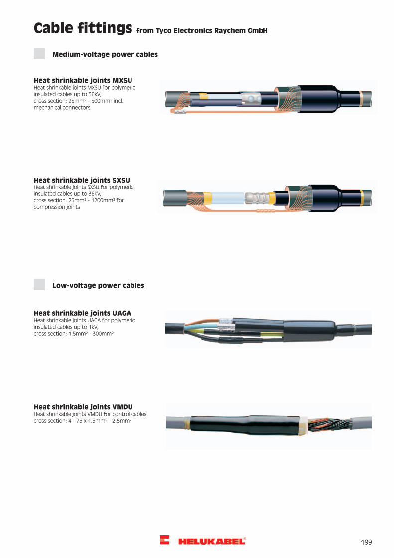
199
Heat shrinkable joints MXSU Heat shrinkable joints MXSU for polymeric insulated cables up to 36kV, cross section: 25mm² - 500mm² incl. mechanical connectors
Heat shrinkable joints SXSU Heat shrinkable joints SXSU for polymeric insulated cables up to 36kV, cross section: 25mm² - 1200mm² for compression joints
Heat shrinkable joints UAGA Heat shrinkable joints UAGA for polymeric insulated cables up to 1kV, cross section: 1.5mm² - 300mm²
Heat shrinkable joints VMDU Heat shrinkable joints VMDU for control cables, cross section: 4 - 75 x 1.5mm² - 2,5mm²
Medium-voltage power cables
Low-voltage power cables
Cable fittings from Tyco Electronics Raychem GmbH

200
Shrink-on tube SK-D heavy walled with inner adhesive
Shrink-on tube SK-D
Properties
Material Crosslinked Polyolefine with internal adhesive Colour: black
Technical Data Temperature range: -55°C up to +90°C Shrinking temperature: +120°C Shrinking rate: 3 : 1 Dielectric Strength: 20kV/mm Adhesive softening point: +80°C up to +90°C
Application For protection of cable joints and terminations for usage at low voltage (600V).
Dimensions and specifications may be changed without prior notice.
Interior diameter before shrinking in mm
Interior diameter after shrinking in mm
Wall thickness after shrinking in mm
Rods to in mm
8,9 3,0 1,8 1,2213,0 4,1 2,4 1,2219,1 6,1 2,4 1,2227,9 8,9 3,0 1,2238,1 11,9 4,1 1,2250,8 16,0 4,1 1,2268,1 22,1 4,1 1,2289,9 30,0 4,1 1,22
119,9 39,9 4,2 1,22
Shrink-on tube SK-D heavy walled with inner adhesive
You can find detailed informationin our new HELUTOP® brochure
- Product range of cable glands
- clear display
- detailed description
You can find detailed information in our accessories catalogue.This catalogue will give you a comprehensive overview of the products.

201
Cable ties
Shrink tubing
Cable conduit
Additional accessories
Cable ties T Cable ties with plastic lugs for bundling and mounting cables and wires.
Material polyamide 6.6 halogen-free, silicone-free
Technical Data Temperature range: -40°C up to +80°C flammability according to UL94 V2
Cable ties E Cable ties made of stainless steel with ball locking system for use under extreme stresses such as high temperatures, caustic environ-ment, high tensile load.
Material Stainless steel
Technical Data Temperature range: -80°C up to +538°C. Approvals: GL, DNV, Lloyd’s, UL
Shrinking tubing SPSP coils Polyolefine shrink tubing for restoring insulation, for sealing electrical components.
Material PO (Polyolefine) self-clearing
Technical Data Temperature range: -55°C up to +135°C Shrinking temperature: +100°C, shrinkage rate: 2:1
Helucond PA6-UL-F/B Cable protecting hose, heavy, for high mechanical loads, high load capacity.
Material Mod. polyamide PA 6. halogen-free, cadmium-free. black: UV-resistant. Flammability according to UL 94: V0
Technical Data Temperature range: -40°C up to +120°C (briefly: up to +160°C) Load/100mm for NW 16/17: approx. 750 N
Quick plug coupling For secure and fast connection, fitting for parallel coiled flexible tubes, type HELUcond.
Material PA
Technical Data Protection class: from IP 65
SH system mount System mount for flexible tube HELUcond. Universal system mount with optional brackets for external loads.
Material Polyamid PA 6. Halogen-free. Flammability according to UL 94: HB
Technical Data Temperature range: -40°C up to +110°C

202
Tools
WK Electro-hydraulic radial piston pump
Technical Data
Complete with transport cart, electrical controls, oil sight glass, motor safety switch, foot switch with 3-point safety control, safety valve, solenoid valve and 3 m high-pressure hoseWithout pressing head.Optionally available as 400 V variant.
Part no. 906721
WK-API 18
Technical Data
2
2
Part no. 906647
WK Electro-hydraulic battery pump This battery pump is suitable for the operation of hydraulic cutting and pressing tools up to max. 700 bar operating pressure.
Technical Data
Part no. 906207
Cable cutter KST 1 Cable cutter KST 1 with telescope grip for cutting range up to 26 mm.
Part no. 99087

203
CCC-Certification for ChinaThe HELUKABEL® GmbH had obtain for their products the CCC-Certification for the following products:
PVC insulated and PVC sheathed oil-resistant flexible cables according to GB 5023.7-1997 227 IEC 74 (RVVYP) 300/500V 0,5-2,5 mm2 (2-60 cores)227 IEC 75 (RVVY) 300/500V 0,5-2,5 mm2 (2-60 cores)Colour: grey H05 VV5-FH05 VVC4V5-K
PVC insulated flexible calbes and wires according to GB 5023.5-1997227 IEC 06 (RV) 300/500 0,75-2,5 mm2 (2-41 cores)
JZ-500, OZ-500, JB-500, OB-500,Y-CY-JZ, Y-CY-OZ, Y-CY-JB, Y-CY-OB,SY-JZ, SY-OZ, SY-JB, SY-OB,JZ-HF, OZ-HF, JZ-HF-CY, OZ-HF-CY,F-CY-JZ, F-CY-OZ, OZ-BL, OZ-BL-CY
PVC insulated non-sheathed calbes and wires according to GB 5023.3-1997227 IEC 02 (RV) 450/750 1,5-240 mm2
227 IEC 06 (RV) 300/500 0,5-1 mm2
H05 V-KH07 V-K

204
Product certificates document the tested quality level of our products
ISO 9000ff is used as the basis for quality management processes carried out at HELUKABEL®. Product certificates issued by accredited institutions also make it easier for you to evaluate your suppliers.
Achieving success through quality and innovation
Our continuous quality improvement process enables us not only to maintain a consistently high quality standard, it also ensures continued development and new product development.
Our commitment to protexting the environment can be seen in our-rate environment management systems.

215
A
Adapters 160 - 161
B
Bolt connector 190
BUS Cables 166 - 169
C
Cable clamps 192
Cable conduit with inner striations 182
Cable connection RSTI 196
Cable cutter KST 1 200
Cable grips 182
Cable installation grips 182
CAN Bus 166
Command Cable UL (LiYCY) 116 - 117
Command Cable UL (LiYCY-TP) 120 - 121
Command Cable UL (LiYY) 117
Command Cable UL (LiYY-TP) 118 - 119
Coupling plug RSTI-CC 196
D
DATAFLAMM 112
DATAFLAMM-C 113
DATAFLAMM-C-PAAR 114
F
F-CY-JZ 65 - 66
Fibre Optic Breakout Cable robust, flexible 173 - 174
Fibre Optic Cable flexible 170 - 172
Fibre Optic Indoor/Outdoor Cable 176
Fibre Optic Outdoor Cable 177 - 179
Fibre Optic Outdoor Cable 180
FIVENORM 106
H
H05Z-K/H07Z-K 108
H07 RN-F 97 - 98
H07 V-K/(H)07 V-K 104
H07RN-F/SOOW 99
Heat shrinkable joints MXSU 197
Heat shrinkable joints SXSU 197
Heat shrinkable joints UAGA 197
Heat shrinkable joints VMDU 197
HELUTHERM® 145 107 - 108
HELUTHERM® 145 MULTI 100 - 101
HELUTHERM® 145 MULTI-C 102 - 103
HELUTOP® HT 183
HELUTOP® HT-E 183
HELUTOP® HT-MS 183
HELUTOP® MS-EP4 183
HELUWIND® WK (N)A2XH 57
HELUWIND® WK 101 H 29
HELUWIND® WK 103k EMV D-Torsion 18 - 19
HELUWIND® WK 103k-Torsion 16 - 17
HELUWIND® WK 103w EMV D-Torsion 14 - 15
HELUWIND® WK 103w-Torsion 12 - 13
HELUWIND® WK 135 EMV D-Torsion 22 - 23
HELUWIND® WK 135-Torsion 20 - 21
HELUWIND® WK 137 EMV D-Torsion FT4 26 - 27
HELUWIND® WK 137-Torsion FT4 24 - 25
HELUWIND® WK 300w-Torsion 1,8/3kV 32
HELUWIND® WK 303w-Torsion UL/CSA 33
HELUWIND® WK 305-Torsion 1,8/3kV 34
HELUWIND® WK 335-Torsion 2,0/3,3kV UL/CSA 35
HELUWIND® WK Brandmeldekabel-Torsion 28
HELUWIND® WK DLO 2kV 40
HELUWIND® WK H07BN4-F WIND-Torsion 30
HELUWIND® WK MS-Multi-Torsion 38
HELUWIND® WK MS-Multi-Torsion UL/CSA 39
HELUWIND® WK MS-Single-Torsion 36
HELUWIND® WK MS-Single-Torsion UL/CSA 37
HELUWIND® WK POWERLINE ALU 0,6/1kV 43
HELUWIND® WK POWERLINE ALU 1,8/3kV 45
HELUWIND® WK POWERLINE ALU halogen free 47
HELUWIND® WK POWERLINE ALU robust 0,6/1kV 44
HELUWIND® WK POWERLINE ALU robust 1,8/3kV 46
HELUWIND® WK POWERLINE ALU Tower 49
HELUWIND® WK POWERLINE Blade ALU 51
Glossary of Therms
Types Page Types Page

216
HELUWIND® WK POWERLINE Blade Copper 50
HELUWIND® WK POWERLINE Copper Tower 48
HELUWIND® WK RHH/RHW 2-ALU 41
HELUWIND® WK THERMFLEX 145 31
HELUWIND® WK-Multiclamp 193
I
Industrial Ethernet 164 - 165
J
JZ-500 62 - 63
JZ-500 Cold 64
JZ-500 HMH 69 - 70
JZ-500 HMH-C 71 - 72
JZ-600 77 - 78
JZ-600 HMH 83 - 84
JZ-600 HMH-C 85 - 86
JZ-600 UL/CSA 87 - 88
JZ-600-Y-CY 79 - 80
JZ-600-Y-CY UL/CSA 89 - 90
JZ-602 91 - 92
JZ-602-CY 93 - 94
JZ-603 95
JZ-603-CY 96
JZ-604 TC TRAY CABLE 142- 143
JZ-604-YCY TC TRAY CABLE 144
K
KAC-U washers 185
M
Machine outlet IP65 163
Machine outlet IP67 162
MEGAFLEX 500 73 - 74
MEGAFLEX 500-C 75 - 76
Multiflex 600 150
Multiflex 600 C 151
N
N2XH 56
N2XS(F)2Y 61
N2XS2Y 58
NA2XS(F)2Y 61
NA2XS2Y 59
NA2XY 55
NAYY 54
NFPA 128 - 129
NYY-J and NYY-O 52 - 53
P
PAAR-TRONIC-CY 110 - 111
Plastic-fibre cable industry 175
Plugs 160 - 161
Profibus L2 168
Profibus SK 167, 169
PROFInet Type C 164
S
Shrink-on tube SK-D 198
Single 600-CY-J/-O 82
Single 600-J/-O 81
SUPER-PAAR-TRONIC 340-C-PUR 127
SUPER-PAAR-TRONIC-C-PUR 126
SUPERTRONIC® -C-PURÖ 125
SUPERTRONIC® -PURÖ 122
SUPERTRONIC-330 PURÖ 124
SUPERTRONIC-330-C PURÖ 126
T
THHN/THHW Einzelader 109
Topflex® 600 VFD 152
Topflex® 650 VFD 153
TORDIERFLEX 165
TRAYCONTROL 300 130 - 131
TRAYCONTROL 300 TP 134 - 135
TRAYCONTROL 300-C 132 - 133
TRAYCONTROL 300-C TP 136 - 137
TRAYCONTROL 500 138 - 139
TRAYCONTROL 500-C 140 - 141
TRAYCONTROL 600 145 - 146
TRAYCONTROL 600-C 147
TRAYCONTROL 610 OIL RES II, WTTC, FT4 148 - 149
Glossary of Therms
Types Page Types Page

217
W
WK (N)A2XH 57
WK 101 H 29
WK 103k EMV D-Torsion 18 - 19
WK 103k-Torsion 16 - 17
WK 103w EMV D-Torsion 14 - 15
WK 103w-Torsion 12 - 13
WK 135 EMV D-Torsion 22 - 23
WK 135-Torsion 20 - 21
WK 137 EMV D-Torsion FT4 26 - 27
WK 137-Torsion FT4 24 - 25
WK 300w-Torsion 1,8/3kV 32
WK 303w-Torsion UL/CSA 33
WK 305-Torsion 1,8/3kV 34
WK 335-Torsion 2,0/3,3kV UL/CSA 35
WK Brandmeldekabel-Torsion 28
WK DLO 2kV 40
WK Electro-hydraulic battery pump 200
WK Electro-hydraulic radial piston pump 200
WK H07BN4-F WIND-Torsion 30
WK MS-Multi-Torsion 38
WK MS-Multi-Torsion UL/CSA 39
WK MS-Single-Torsion 36
WK MS-Single-Torsion UL/CSA 37
WK POWERLINE ALU 0,6/1kV 43
WK POWERLINE ALU 1,8/3kV 45
WK POWERLINE ALU halogenfrei, 1,8/3kV 47
WK POWERLINE ALU robust 0,6/1kV 44
WK POWERLINE ALU robust 1,8/3kV 46
WK POWERLINE ALU Tower 49
WK POWERLINE Blade ALU 51
WK POWERLINE Blade Copper 50
WK POWERLINE Copper Tower 48
WK RHH/RHW 2-ALU 41
WK THERMFLEX 145 31
WK-AL compression cable lug 185
WK-AL compression cable lug FG extruded 186
WK-AL compression connector 188
WK-AL/CU compression cable lugs 187
WK-AL/CU compression connector 189
WK-API 18 200
WK-CU compression cable lug 184
WK-Multiclamp 193
Y
Y-CY-JZ 67 - 68
Glossary of Therms
Types Page Types Page

218
Part No. Page Part No. Page Part No. Page
From Part No.10001 – 49615
10001 – 10047 62
10048 – 10168 63
10169 62
10170 63
10172 – 10173 62
10174 – 10176 63
10177 62
10178 – 10182 63
10183 62
10184 – 10536 63
10550 – 10615 77
10616 – 10746 78
10750 – 10797 64
10881 – 10904 81
10910 – 10933 82
11201 – 11220 69
11221 – 11331 70
11332 – 11334 69
11335 – 11341 70
11342 – 11347 71
11348 – 11350 72
11464 – 11563 79
11574 – 11629 80
11656 – 11689 71
11700 – 11813 72
11815 – 11846 87
11847 – 11876 88
11880 – 11911 87
11912 – 11941 88
12345 – 12371 89
12372 – 12405 90
12410 – 12436 89
12437 – 12470 90
12723 – 12746 83
12747 – 12804 84
12850 – 12877 85
12878 – 12907 86
13137 80
13139 – 13140 63
13147 80
13344 – 13367 73
13368 – 13489 74
13500 – 13515 75
13516 – 13597 76
16157 – 16168 68
16169 – 16175 67
16176 – 16183 68
16196 – 16239 67
16240 – 16314 68
16315 – 16316 67
16317 – 16318 68
16320 – 16343 65
16344 –16452 66
16453 67
16454 – 16468 68
16490 65
16491 – 16493 66
17001 – 17056 111
17172 67
19101 – 19141 126
19970 – 19995 111
21001 – 21010 110
21011 – 21064 111
32001 –32015 52
32016 – 32088 53
32089 – 32103 52
32104 – 32300 53
32322 – 32325 54
32481 – 32491 58
32534 – 32544 59
32556 – 32559 52
32571 – 32580 60
32612 – 32619 61
33121 – 33136 55
34090 – 34349 98
37001 – 37028 97
37029 – 37154 98
39025 – 39039 99
49583 – 49615 122
Part No. index

219
Part No. Page Part No. Page Part No. Page
From Part No.49653 – 81882
49653 – 49685 123
49764 – 49796 124
49797 – 49829 125
49830 – 49870 127
50998 – 51558 107
52194 – 52197 102
52198 – 52292 103
52300 – 52361 112
52365 – 52429 113
52430 – 52431 112
52435 – 52484 114
53111 – 53261 56
53376 – 53387 100
53388 – 53549 101
59472 – 59653 108
59760 – 59810 136
59811 – 59836 137
61928 – 61980 134
61981 – 61998 135
61999 136
62502 – 62554 150
62556 –62605 151
62625 –62684 130
62685 – 62709 131
62710 – 62765 132
62766 – 62793 133
62794 – 62800 134
62802 – 62812 139
62813 – 62868 140
62869 – 62875 141
62876 – 62884 153
62902 – 62942 145
62943 – 62969 146
62970 – 62988 145
62989 – 62996 146
62997 – 63078 147
63079 – 63133 138
63136 150
63137 152
63138 153
63139 – 63155 152
63156 – 63163 153
63164 138
63165 – 63199 139
6320_ – 6332_ 109
63331 – 63401 109
64075 – 64330 106
65044 – 65087 117
65214 – 65242 118
65243 – 65285 119
65314 – 65349 120
65350 – 65385 121
69661 – 69714 142
69715 – 69737 143
69804 – 69826 144
71437 31
74006 19
75486 – 75496 31
78177 – 78180 19
80180 – 80187 180
80188 – 80211 181
80212 – 80218 180
80219 181
80220 180
80223 – 80227 181
80264 – 80281 178
80363 – 80382 173
80388 – 80532 177
80534 173
80629 – 80630 177
80681 – 80851 178
81036 – 81038 173
81108 – 81382 181
81501 171
81611 – 81882 177
Part No. index

220
Part No. Page Part No. Page Part No. Page
From Part No.81903 – 707129
81903 – 81904 169
81905 171
82032 – 82033 177
82431 178
82488 94
82648 181
82780 – 82940 94
82941 – 82942 93
82943 – 82944 94
82945 – 83000 93
83001 – 83024 92
83031 – 83104 91
83137 – 83227 115
83254 – 83280 116
83286 – 83344 117
83565 91
83650 – 83708 95
83709 – 83773 96
83774 – 83809 120
83810 – 83845 121
83904 – 83932 118
83933 – 83975 119
83976 – 83997 116
99087 202
702485 28
702513 – 702863 40
703041 – 703152 15
703156 – 703171 40
703285 – 703288 23
703289 21
703290 23
703291 – 703323 21
703328 19
703390 – 703404 30
703668 – 703671 21
703672 23
703673 21
703674 – 703804 23
703862 40
703920 – 703922 13
703925 – 703926 13
703930 13
703932 – 703933 13
704038 21
704039 – 704167 23
704267 13
704268 15
704269 13
704287 – 704295 13
704366 – 704368 13
704369 15
704471 21
704675 – 704698 23
704699 – 704745 21
704749 – 704808 15
704809 – 704876 13
704877 – 704939 19
704940 – 705026 17
705031 – 705034 57
705037 19
705038 17
705039 15
705040 13
705045 23
705046 – 705108 21
705719 – 705759 25
705829 15
706084 – 706089 43
706194 – 706287 149
706318 13
706399 – 706407 32
706408 43
706432 32
706452 – 706460 34
706461 – 706530 27
706557 – 706558 31
706576 – 706577 51
706578 45
707006 23
707062 – 707064 43
707097 – 707104 44
707129 21
Part No. index

221
Part No. Page Part No. Page Part No. Page
From Part No.707432 – 906721
707432 45
707454 – 707464 21
707494 – 707531 29
707638 23
707647 – 707648 45
707650 17
707651 21
707692 – 707695 46
708332 – 708335 36
708340 – 708344 35
708425 – 708428 38
708436 21
708470 – 708474 49
708475 – 708479 48
708678 – 708679 50
708687 21
708702 – 708710 37
708711 – 708716 36
708717 – 708725 37
708726 – 708733 38
708734 – 708745 39
708746 – 708754 41
708857 40
708874 – 708877 33
708974 – 708984 25
709143 – 709146 47
800067 167
800109 – 800649 170
800754 – 800762 179
800980 176
801354 164
801421 165
801727 173
801733 175
801982 168
802131 – 802142 179
802186 166
802792 174
803037 – 803038 182
803346 – 803349 172
803923 – 803924 182
803934 – 803935 174
905163 – 905919 184
906172 – 906185 189
906207 202
906209 – 906210 191
906212 189
906406 190
906436 – 906459 187
906460 191
906461 – 906477 187
906478 – 906494 189
906495 – 906510 191
906511 – 906521 190
906524 – 906538 186
906539 – 906561 188
906647 – 906721 202
Part No. index

222
www.helukabel.com
Key Account Manager Wind Energy / Uwe Schenk Germany Phone: +49 7150 9209-624 PC-Fax: +49 7150 9209-5624 Mobile: +49 0171 6068 424 E-Mail: [email protected]
Project Manager Wind Energy Joachim Koch Phone: +49 7150 9209-135 PC-Fax: +49 7150 9209-5135 E-Mail: [email protected]
Cable Accessories Susanne Möller Phone: +49 7150 9209-760 PC-Fax: +49 7150 9209-5760 E-Mail: [email protected]
Data, Network & Bus Technology Kenny Fuchs Phone: +49 7150 9209-179 PC-Fax: +49 7150 9209-5179 E-Mail: [email protected]
Please check all applicable products for which you need information:
We would like:
HELUKABEL GmbH
Dieselstraße 8-12 D-71282 Hemmingen / Germany
Phone +49 7150 9209-0Fax +49 7150 81786
E-Mail: [email protected]
Cables & Wires (full line)
Cable Accessories
Data, Network & Bus Technology
Media Technology
Photovoltaic Installations
General documentation
A visit from a factory representative
A quotation for:
Comment / Note:
How to get in touch with our Wind Power Specialists:

Our general terms and conditions of sale and payment are valid, visible at www.helukabel.com
Note
Technical alternations© HELUKABEL® GmbH HemmingenSubject to technical alternations. All illustrations, symbolic, inscriptions, markings, numbering etc., on the outer jacket are therefore without guarantee. Differences in colour between photos and deliverot goods cannot be avoided. All rights for reprinting or reproduction of text and illustrations, in whole or in part, reserved. The transfer or copyrights principally requires the written permission of HELUKABEL® GmbH. Our general terms and conditions of sale and payment are valid, visible at www.helukabel.de.
The length markingThe length marking, which is not calibratable, represents a tool, e.g. for a simple material allowance determination or for the specifications of the residual length that remains on the drum. The deviation of the wire length represented by the length marking can be up to 1%. Incomplete length markings, length markings missing on sections or deviations of the wire length represented by the length marking do not establish a statutory duty. Only calibrated measuring devices must be used to determine the wire length.
Safety instructionsThe cables and wires described in the catalog are manufactured in accordance with domestic and international standards as well as in-house standards. Adherence to the then valid safety guidelines, standards and legal regulations is provided for application safety. Product specific dangers can be excluded assumed a proper and professional installation and usage is guaranteed. For each product, this catalog describes general information for usage. Independent of the above, the specifications of the appropriate DIN VDE specifications are valid. However, the installation and processing can only be performed by professional electricians.
Photo: Helukabel® – Research, development and production Windsbach/Nuremberg

SDZe
CO
M/0
313/
2,5E
N/W
a
Other branches – international:France · Italy · Switzerland · NetherlandsBelgium · Sweden · Czech RepublicPoland · Russia · Turkey · Canada · South AfricaMalaysia · Singapore · Thailand
HELUKABEL® GmbH (Headquarters)Dieselstraße 8-12 · 71282 Hemmingen GermanyPh. +49 7150 9209-0 · Fax +49 7150 81786
HELUKABEL® USA, Inc. (US)1490 Crispin Drive, Elgin, IL 60123 Ph. +1 847 9305118 · Fax +1 847 6228766
HELUKABEL® Int‘l Trading (CN)(Shanghai) Co., Ltd. 1st Floor, Bldg No. 4, 668 HengAn Rd., PudongNew Dist. Shanghai · PRC - 200137 ShanghaiPh. +86 21 58693999 · Fax +86 21 58693666
HELUKABEL® KOREA Co., Ltd. (KR)521-17 Daejeo 2 Dong Gang-seo GuBusanPh. +82 51 9728646 · Fax +82 51 9728649
HELUKABEL® INDIA PVT. LTD. (IN)F-305 Kailash Complex, Hiranandani GardensLink Road, Vikhroli WestIND - Mumbai 400 079Ph. +91 22 25185841 · Fax +91 22 25185839