Catalogo Unità rotanti - FARBO PNEUMATIC · The linear movement changes to rotational movement by...
78
355 While the slide cylinder transports objects vertically and horizontally, the rotary cylinder moves objects rotationally, and the adjustment of the rotational angle is possible. Rotary Cylinder www.jrt fa .com
Transcript of Catalogo Unità rotanti - FARBO PNEUMATIC · The linear movement changes to rotational movement by...

355
While the slide cylinder transports objects vertically and horizontally,
the rotary cylinder moves objects rotationally,
and the adjustment of the rotational angle is possible.
Rotary Cylinder
www.jrtfa.com

Hydraul ic
About the product
Single TypeSRJ (Rack & Pinion Type)
SDRJ (Rack & Pinion Type)
RTU (Finger Attachable)
RHU (Finger Attachable)
RJC
Double Type
Swivel Uni t
350
356
362
370
376
356
362
370
376
382
349
RHUM (Finger Assembly) 388
Rotary Cylinder
www.jrtfa.com

About the Product
Rotary Cylinder
1. Classification of the rotary cylinder (rotary actuator)
Rotary cylinder: An apparatus that transforms the energy of pressurized air into rotational movement
1) Vane type
The vane type is operated by the air pressure that operates on the hydraulic area of the fixedwall installed on the cylinder.
Single vane: 270 to 300 , Double vane; 70 to 120 , Triple vane; below 60
Structurally, it's difficult to shut air completely.
2) Rack & pinion type
When the center that is geared to the rack gear linked directly to the piston, torque is acquired.The type is most efficient among rotary cylinders. It's easy to install cushions. Also, componentforces are generated at the pressure angle of the rack gear. Also, friction increases becausehorizontal thrust on the backside of the gear or piston occurs, but efficiency of 80 to 90 couldbe obtained.
3) Screw type
When the stroke is enlarged as the straight movement changes to the rotational movement with thescrew on the thrust axis in the middle, the rotational angle could be great, but the exterior shouldbecome larger. The efficiency ratio is about 80%.
4) Crank type
The linear movement changes to rotational movement by the crank. The angle of movement islimited to 110 structurally, and the rotational force changes according to the angle of movement.
5) Wheel gear & chain type (hydro type)
The chain linked to the cylinder piston arranged in parallel is geared to the wheel gear.With built-in oil on the part linked to the wheel gear, the type is used in processes thatrequire quiet rotation. Greater than 90% efficiency is possible.
350www.jrtfa.com

2. Process of selecting rotary cylinder
1) Review of the size of the load
(1) Required torque when static power is required;
Ts = F x I (Nm) [ F:The force which is demanded(n), I:From load center distance until in rotary center (m) ]
(2) When the load changes
a) Calculation of the resistance torque
- When there is no change in load (horizontal use) K=2
- When there is change to the load (vertical use) K=5
b) Calculation of the acceleration torque
(i) Acceleration torque Ta = 5 x I x ( /t2) x 10-2 / 10,000(Nm) [I : Inertial moment (Nm)]
: rotary actuator angle (rad), 90 = 1.5708(rad), 180 = 3.1416(rad), 270 = 4.7124(rad)
(ii) The inertial momentum is calculated according to the shape and weight of the load.
(iii) Each acceleration is calculated.
= /t(rad/s2) : rotary actuator angle (rad), t : rotary actuator time
c) Calculation of the required torque
Tt = TR + TL
In the angular rotational cylinder torque table, select the model that satisfies the equation .
2) Review of allowed energy
a) Calculation of the angular velocity
= /t(rad/s2) : rotary actuator angle (rad), t : rotary actuator time
b) Calculation of the inertial energy of the load
E = 0.5 x I x É2 x 10⁻¹ (mj) / 10,000 [I : Inertial moment (Nm)]
When the inertial energy of the load exceeds the allowable energy of the rotary cylinder type,a mechanism to absorb the impact is required.
351
About the Product
Rotary Cylinder
www.jrtfa.com

a2
1
b
a
1
2I
I
R
dL
L
L
L1
L2
Outline
M : Weight [kg]
Require item
M1 : Weight of part L1[kg]M2 : Weight of part L2[kg]
L : Length of barM : Weight [kg]
M1 : Weight of part a1[kg]M2 : Weight of part a2[kg]
M : Weight [kg]
M : Weight [kg]
I1 :The moment of inertia which passes the center ofthe load located at the top and that parallels to therotation axis
I2 :The moment of inertia which located around therotation axis of the arm
M1 :Weight at the top of the objectM2 :Weight of the armR :Distance from the rotation axis to the center ofgravity of the load at the top of the object
I1 :Moment of inertia at the loading sideI2 :Moment of inertia at the driving side
Moment of inertia: [ Nm ]
d : Diameter [cm]x0.00098
x0.00098
x0.00098
x0.00098
x0.00098
x0.00098
x0.00098
x0.00098
352
Rotary Cylinder
www.jrtfa.com

Single Type
Double Type
Hydraul ic
SRJ Rack & Pinion TypeSRJ Rack & Pinion Type
SDRJ Rack & Pinion TypeSDRJ Rack & Pinion Type
RJCRJC
Type
40
0.184P
0.093P90 / 180
90 / 180
16
20
25
30
0.8
15
5.7
3.5
90 / 180 0.608P
0.328P
1.2
90 / 180
90 / 180
3.5
5.7
1.481P 3.62 / 4.33
0.69 / 0.80
0.41 / 0.47
1.2
0.8
12
2.08 / 2.45
1.17 / 1.37
PageWeight(kg)
Max Payload (kg)
Radial ThrustRotationAngle
Practical Torque(Nm)
Type RotationAngle
Practical Torque(Nm)
50
63
16
20
Weight(kg)Radial Thrust
90 / 180 0.235P
90 / 180
90 / 180
1.040P
0.491P 10
25
16
30
12
3.169P
1.491P
Max Payload (kg)
8 8
14
14.715P
6.455P
90 / 180
90 / 180
90 / 180
90 / 180 6.82 / 6.62
23.02 / 23.00
11.71 / 11.60
Page
32
40
3.88 / 3.76
2.74 / 2.66
2.20 / 2.10
0.86 / 0.82
25
30
40
42
26
16
15
60
80
40
Type
78
40 20
Max Payload (kg)
19.228(P-0.9)
9.908(P-1.3) 62
3.139(P-1.4)90 / 180
90 / 180
90 / 180
Weight(kg)
11.50 /12.00
Radial ThrustRotationAngle
Practical Torque(Nm)
40
32
18.50 /20.00
5.49 / 5.83
Page
356
362
370
P=Air Pressure[bar]
P=Air Pressure[bar]
P=Air Pressure[bar]
353
Rotary Cylinder
www.jrtfa.com

Swivel Uni t
RHU Finger AttachableRHU Finger Attachable
RTU Finger AttachableRTU Finger Attachable
20
Type
34
40
40N
Thrust
12
15
21
20
24
13
10
18
RotationAngle
Practical Torque(Nm)
0.510P
1.570P
1.275P
3.021P
Weight(kg)
Max Payload (kg)
6.80
2.26
4.10
8.84
Radial
180
Page
180
180
180
Type RotationAngle
Practical Torque(Nm)
Max Payload (kg)
Radial Thrust
20
40
55
1.2
0.775P
0.169P 0.68
Weight(kg) Page
0.6
3.24
1.971.21.990
90 2.81.413P 1.6
90
382
376
P=Air Pressure[bar]
P=Air Pressure[bar]
354
RHUM Finger AssemblyRHUM Finger Assembly
20
Type
34
40
40N
Thrust
12
15
21
20
24
13
10
18
RotationAngle
Practical Torque(Nm)
0.510P
1.570P
1.275P
3.021P
Weight(kg)
Max Payload (kg)
Radial
180
Page
180
180
180
388
P=Air Pressure[bar]
Rotary Cylinder
www.jrtfa.com

355
While the slide cylinder transports objects vertically and horizontally,
the rotary cylinder moves objects rotationally,
and the adjustment of the rotational angle is possible.
Rotary Cylinder
www.jrtfa.com

Rotary actuator of rack & pinion type
A built in wearing provide long unit life
Low friction seal provide high torque with enveloperatio
End stopper for precise angular position(Can use shock absorber instead of stopper)
Rotation tablefast and economic positioning of therotation table
Kineticspinion/toothed rack system for low tolerancetransmission of drive power in one rotationmovement
Body
Drive
high-tensile aluminum body withlightest possible because ofhard anodizing
SRJ-16,20,25,30,40
Rack & pinion type
Stop damperdirect cylinder bodyposition inquiry
double acting pneumaticcylinder
356
Character
Rotary Cylinder
www.jrtfa.com

SRJ
Bal l Bear ing
Bearing Housing
Bearing Housing
Back Cover(A)
Piston packing
Wear Ring
Piston
Driv ing Shaft
Stopper Bol t
Stopper Nut
Turn Table
Back Cover(B)
Rotary Body
357
Exploded view
www.jrtfa.com

90 RS 2 HT
ProductName
16, 20, 25, 30, 40Bore Size
- For angle Option, informus setting direction of
Turning Angle
1 - 1EA2 - 2EA
AbsorberQuantity
RS - Reed switch : 2 wireN - Solid state type, current sinking (NPN) : 3 wireP - Solid state type, current sourcing (PNP) : 3 wireRT - High temperature type (+120 ) : Option
( Reed switch only )
*Option
Sensor Type
1 - 1EA2 - 2EA
SensorQuantity
Nomark - Stopper (Standard)DA - Adjustable Type (Option)N - Non Adjustable Type (Option)Note.SRJ16 - M10 x P1.0SRJ20 - M10 x P1.0SRJ25 - M14 x P1.5SRJ30 - M14 x P1.5SRJ40 - M20 x P1.5
Shock Absorber
Nomark - 1m3M - 3m5M - 5mQ8 - quick connector
( M8-3pin maleLength 0.15m )
Sensor CableLength
SRJ 16 Q8 F8 DA 2- - - - -
Nomark - Standard(for general pneumatic seal)HT - High temperature sealing
sets ( -10 to120 )
Sealing Option
- For high temperature sealing,consult JRT
rotation
- Sensor : Normally Open(NO) is Standard andNormally Close(NC) is option
- For NC Type, add ordering code end "C"ex) RTC - High temperature type,
Normally Close(NC) type
90 - ( 90 ) : Standard180 - ( 180 ) : Standard
The delivery of * mark option is longer than a standard, So inquire of JRT
*
358
F8 - quick connector( M8-3pin famale
Length 3m )
SRJ
Order ing Code
www.jrtfa.com

Speci f icat ion
SRJ
SRJ-16
for ( ) in number 180
REED SWITCHJRTM 2-M5 AIR PORT
M10x1p ABSORBER
359
SRJ16 SRJ20 SRJ25 SRJ30 SRJ40
P=Air Pressure[bar]
Unit
Actual Torque N.m
Kg
Kg
Kg
Kg
Kg
sec
Cm3
degree
sec
bar
Radial payload
Compress load(thrust)
Tensile load(thrust)
Weight( 90 )
Weight( 180 )
Turning Time( 90 )
Turning Time( 180 )
Fitting size
Air consumption(90 /180 )
Repetition Accuracy
Operating pressure
Ambient temperature
Lubrication
Products Name
0.093P
0.8
M5
3.8 / 7.6
0.3 to 0.7
0.2 to 0.5
0.47
-5 to 60
Needless
3 to 7
±0.1
Cushion Stopper or Absorber
0.41
0.184P
1.2
PF(G) 1/8
7.4 / 14.8
0.3 to 1.0
0.2 to 0.8
0.80
0.63
0.327P
3.5
PF(G) 1/8
13.1 / 26.2
0.3 to 1.5
0.2 to 1.0
1.37
1.17
0.608P
5.7
PF(G) 1/8
24.3 / 48.6
0.5 to 1.5
0.3 to 1.0
2.45
2.08
1.480P
15
0.8 1.2 3.5 5.7 15
0.6 1.0 3.0 4.5 8.0
PF(G) 1/8
59.2 / 118.4
0.5 to 1.5
0.3 to 1.0
4.33
3.61
www.jrtfa.com
* After 100 consecutive strokes to end positions

SRJ-20
JRTM
for ( ) in number 180
SRJ-25
for ( ) in number 180
4.5
REED SWITCH
ABSORBER (M10x1.0p)
2-PF(G) 1/8 (AIR PORT)
ABSORBER (M14x1.5p)
JRTMREED SWITCH
2-PF(G) 1/8 (AIR PORT)
360
SRJ
www.jrtfa.com

SRJ-30
SRJ-40
for ( ) in number 180
119922
for ( ) in number 180
JRTMREED SWITCH
ABSORBER (M14x1.5p)
2-PF(G) 1/8 (AIR PORT)
JRTMREED SWITCH
ABSORBER (M20x1.5p)
2-PF(G) 1/8 (AIR PORT)
361
SRJ
www.jrtfa.com

Rotary actuator of rack & pinion type with internaldual piston
Saving power tube by center through bore & easy mount
Identical stop power with a rotation power reducerotation moment of inertia
Integrated bracket to use a shoulder bolt key reducethe tolerance of end position
Kineticspinion/toothed rack system for low tolerancetransmission of drive power in one rotationmovement
Shock absorberadjustable end rotarydriving absorbency
Bodyhigh-tensile aluminum body withlightest possible because ofhard anodizing
SDRJ-16,20,25,30,40,50,63
Rack & pinion type
Mounting blockmounting for inductiveproximity switch
362
Character
Rotary Cylinder
www.jrtfa.com

SDRJ
Bal l Bear ing
Bearing Cover
Back Cover(B)
Absorber
Piston Packing
Wear Ring
Stopper Pin
Back Cover(A)
Piston
Turn Table
O-Ring
Rotary Body
Stopper Bar
Stopper
Driv ing Gear
Stopper Bracket
Stopper Nut
363
Exploded view
www.jrtfa.com

SDRJ
90 RS 2 HT
ProductName
16, 20, 25,30, 40, 50, 63
Bore Size
For angle Option, informus setting direction ofrotation
Turning Angle
1 - 1EA2 - 2EA
AbsorberQuantity
RS - Reed switch : 2 wireN - Solid state type, current sinking (NPN) : 3 wireP - Solid state type, current sourcing (PNP) : 3 wireRT - High temperature type (+120 ) : Option
( Reed switch only )PS - Proximity Sensor(NPN) 8 x 30(mm)PSP - Proximity Sensor(PNP) 8 x 30(mm)PSS - Proximity Sensor(NPN) 8 x 16(mm)PSSP - Proximity Sensor(PNP) 8 x 16(mm)PSL - Proximity Sensor(NPN) 12 x 46(mm)(Only SDRJ50, SDRJ63)PSLP - Proximity Sensor(PNP) 12 x 46(mm)(Only SDRJ50, SDRJ63)
*Option
Sensor Type
1 - 1EA2 - 2EA
SensorQuantity
Nomark - Stopper (Option)DA - Adjustable Type (Standard)N - Non Adjustable Type (Option)Note.SDRJ16 - M12 x P1.0SDRJ20 - M14 x P1.5SDRJ25 - M14 x P1.5SDRJ30 - M20 x P1.5SDRJ40 - M20 x P1.5SDRJ50 - M27 x P3.0SDRJ63 - M27 x P3.0
Shock Absorber
Nomark - 1m3M - 3m5M - 5mQ8 - quick connector
( M8-3pin maleLength 0.15m )
Sensor CableLength
SDRJ 25 Q8 F8 DA 2- - - - -
Nomark - Standard(for general pneumatic seal)HT - High temperature sealing
sets ( -10 to 120 )
Sealing Option
- For high temperature sealing,consult JRT
- Sensor : Normally Open(NO) is Standard andNormally Close(NC) is option
- For NC Type, add ordering code end "C"ex) RTC - High temperature type,
Normally Close(NC) type
90 - ( 90 ) : Standard180 - ( 180 ) : Standard
The delivery of * mark option is longer than a standard, So inquire of JRT
*
364
F8 - quick connector( M8-3pin famale
Length 3m )
Order ing Code
www.jrtfa.com

SDRJ
SDRJ-16
OPPOSITE SIDE
REEDSWITCHJRTM 6
SHOCK ABSORBER
2-M5 AIR PORT
365
-5 to 60
Needless
3 to 7
±0.1
Stopper or Absorber
SDRJ16
±0.1
-5 to 60
P=Air Pressure[bar]
Unit
Actual Torque N.m
Kg
Kg
Kg
Kg
Kg
sec
Cm3
degree
sec
bar
Radial payload
Compress load(thrust)
Tensile load(thrust)
Weight( 90 )
Weight( 180 )
Turning Time( 90 )
Turning Time( 180 )
Fitting size
Air consumption(90 /180 )
Repetition Accuracy
Operating pressure
Ambient temperature
Lubrication
Products Name
0.235P
8
M5
8.8 / 17.7
0.3 to 1.0
0.2 to 1.4
0.82
Cushion
0.86
8
7
SDRJ20
0.49P
12
PF(G) 1/8
19.7 / 39.5
0.3 to 1.0
0.2 to 1.8
2.11
2.15
10
9
SDRJ25
1.039P
15
PF(G) 1/8
41.6 / 83.2
0.3 to 1.0
0.2 to 1.8
2.66
2.74
14
10
SDRJ30
1.49P
16
PF(G) 1/8
66.6 /119.9
0.4 to 1.2
0.3 to 1.0
3.76
3.88
16
12
SDRJ40
3.165P
26
PF(G) 1/8
126.3 / 252.5
0.5 to 1.4
0.4 to 1.2
6.62
6.82
25
20
SDRJ50
6.448P
32
PF(G) 1/8
251.3 / 502.7
0.7 to 3.5
0.6 to 3.2
11.60
11.66
30
26
SDRJ63
14.7P
42
PF(G) 1/4
589.8/1179.6
0.8 to 3.7
0.7 to 3.5
22.50
22.90
40
32
Speci f icat ion
www.jrtfa.com
* After 100 consecutive strokes to end positions

SDRJ-20
SDRJ-25
OPPOSITE SIDE
2-PF(G)1/8 (AIR PORT)
2-ABSORBER (M14x1.5p)2-PROXIMITY SENSORM8x2MM(JPM8)
2-PF(G)1/8 (AIR PORT)
2-ABSORBER (M14x1.5p)2-PROXIMITY SENSORM8x2MM(JPM8)
for AIR HOSE
for AIR HOSE
366
SDRJ
www.jrtfa.com

SDRJ-30
OPPOSITE SIDE
SDRJ-40
OPPOSITE SIDE
2-PROXIMITY SENSORM8x2MM(JPM8)
2-ABSORBER (M20x1.5p)
2-PF(G)1/8 (AIR PORT)
for AIR HOSE
for AIR HOSE
2-ABSORBER (M20x1.5p)2-PROXIMITY SENSORM8x2MM(JPM8)
2-PF(G)1/8 (AIR PORT)
367
SDRJ
www.jrtfa.com

SDRJ-50
Opposite side M14 DP25
SDRJ-63
140
2-PF(G)1/8AIR PORT
2-ABSORBER(M27x3p)
2-PROXIMITY SENSORM12x4MM(JPM12) 2-ABSORBER(M27x3p)
for PROXIMITY SWITCH
2-PF(G)1/4AIR PORT
for AIR HOSE
for AIR HOSE
2-PROXIMITY SENSORM12x4MM(JPM12)
368
SDRJ
www.jrtfa.com

Notes
www.jrtfa.com 369

Rotary actuator of driving shaft coupled chain join pistontype
Built in hydro cushion reduce shock at end of rotation andincrease road stopping capacity
Smoothly rotation at field of low speed
A driving shaft with center through bore assemble easilyinto a module
Attention to select the position tap hole & direction ofrotation
Body
Drive
high-tensile aluminum body with lightestpossible because of hard anodizing
Stop screwend stop adjustable viaadjustment screw
RJC-40,63,80
Air hydraulic
double acting pneumaticcylinder
370
Character
Rotary Cylinder
www.jrtfa.com

RJC
Housing BlockBal l Bear ing
Cyl inder Tube
Rod Packing
Bal l Bear ing
Adjust Plate
Adjust Bol t
Piston PackingWear RingMagnetMagnet Bracket
PistonStopper
StopperFlange Rol ler Chain
Cushion Needle
O-Ring
O-Ring
Stopper Plate
Connector
Rod Cover
Tie Rod
O-Ring
Oi l ing Plug
Driv ing Shaft
Snap Ring
Flange
371
Exploded view
www.jrtfa.com

RJC
90 RS 2 HT
ProductName
40N, 63N, 80NBore Size
For angle Option, informus setting direction ofrotation
Turning Angle
RS - T02R ( reed switch : 2 wire )Sensor Type
1 - 1EA2 - 2EA
SensorQuantity
Nomark - 1m3M - 3m5M - 5mQ8 - quick connector
( M8-3pin maleLength 0.15m )
Sensor CableLength
RJC Q8 F8- - - -
Nomark - Standard(for general pneumatic seal)HT - High temperature sealing
sets ( -10 to 120 )
Sealing Option
40N T
ANGULAR BEARINGNomark : Ball BearingC : Angular Bearing ( Compress )T : Angular Bearing ( Tensile )
- For high temperature sealing,consult JRT
90 - ( 90 ) : Standard180 - ( 180 ) : Standard
The delivery of * mark option is longer than a standard, So inquire of JRT
*
372
F8 - quick connector( M8-3pin famale
Length 3m )
Order ing Code
www.jrtfa.com

RJC
373
-5 to 60
Needless
3 to 7
±0.1
Absorber
RJC63
±0.1
-5 to 60
P=Air Pressure[bar]
Unit
Actual Torque N.m
Kg
Kg
Kg
Kg
Kg
sec
Cm3
degree
sec
bar
Radial payload
Compress load(thrust)
Tensile load(thrust)
Weight( 90 )
Weight( 180 )
Turning Time( 90 )
Turning Time( 180 )
Fitting size
Air consumption(90 /180 )
Repetition Accuracy
Operating pressure
Ambient temperature
Lubrication
Products Name
9.898(P-1.3)
62
PF(G) 1/4
395.9 / 791.8
1.0 to 4.0
0.7 to 3.5
12
Cushion
11.5
32
32
RJC80
19.208(P-0.9)
78
PF(G) 1/4
766.0 / 1532.1
2.0 to 5.0
1.5 to 4.0
20
18.5
40
40
RJC40
3.136(P-1.4)
40
PF(G) 1/8
127.7 / 255.3
0.7 to 3.0
0.5 to 2.5
6.5
6
20
20
RJC-40
CheckValve6
(JRT-02)
for ( ) in number 180
Speci f icat ion
www.jrtfa.com
* After 100 consecutive strokes to end positions

374
RJC-63142
40
146
80
51 42
16.5
78
78
1652
20
16322
4080
17
81
12
REED SWITCH
229.5
(294.5)
158
6-M8 DP18
4040
5530
3437
67.5
8060
340
99
160147
125
10 10TURN
2-AIR PORTPF(G) 1/4
2x4-M10 DP20
PCD 42
(JRT-02)
RJC-80
PCD 56
2-AIR PORTPF(G) 1/4
1662
98
17
REED SWITCH
88
40
44
(354.5)
279.5
2x4-M10 DP20
82.5
1007570
5050
192
16
16490
183 4524
44550
13 192
119
1771556-M10 DP20
?100
100
30
176
8821.5
5261
( JRT-02)
for ( ) in number 180
for ( ) in number 180
RJC
www.jrtfa.com

Notes
www.jrtfa.com 375

Kineticpinion/toothed rack system for low tolerancetransmission of drive power in one rotationmovement
Intake flangefor connection to application specificadapter plate
Bodyhigh-tensile aluminum body withlightest possible because ofhard anodizing
RTU-25,40,50
Finger attachable 90 swivel unit
Drivedouble acting pneumaticcylinder
Rectangular rotary unit to be able to rotate twogrippers rectangularly mounted unit
In case of using with series AF30 or AF46,easy to assemble into a module
Internal shock absorber reduce shock at end ofrotation and increase road stopping capacity
Light weight grippers (e.g. AF28D) to mount at unitis suitable
Shock absorberadjustable end rotarydriving absorbency
376
CharacterCharacter
Rotary Cylinder
www.jrtfa.com

RTU
Bal l Bear ing
Piston Packing
Rotary Body
Wear Ring
Side Cover
Lower Cover
Piston
Pin
Leg Plate
O-Ring
Stopper Bol t
Absorber Rack
Finger Plate
Shock Absorber
377
Exploded view
www.jrtfa.com

RTU
RS 2 HT
ProductName
25, 40, 50Bore Size
1 - 1EA2 - 2EA
AbsorberQuantity
RS - Reed switch : 2 wireN - Solid state type, current sinking (NPN)P - Solid state type, current sourcing (PNP)RT - High temperature type (+120 ) : Option
( Reed switch only )
*Option
Sensor Type
1 - 1EA2 - 2EA
SensorQuantity
Nomark - 2EA Attach (Standard)DA - Piston : Max. 2EA Attach(Option)
Shock Absorber
Nomark - 1m3M - 3m5M - 5mQ8 - quick connector
( M8-3pin maleLength 0.15m )
Sensor CableLength
RTU 25 Q8 F8 DA 2- - - -
Nomark - Standard(for general pneumatic seal)
HT - High temperature sealingsets ( -10 to 120 )
Sealing Option
- For high temperature sealing,consult JRT
- Sensor : Normally Open(NO) is Standard andNormally Close(NC) is option
- For NC Type, add ordering code end "C"ex) RTC - High temperature type,
Normally Close(NC) type
The delivery of * mark option is longer than a standard, So inquire of JRT
*
378
F8 - quick connector( M8-3pin famale
Length 3m )
Order ing Code
www.jrtfa.com

RTU
RTU-252- 5 DP5+0.03
06-M6 dp9
20 dp20+0.03
±0.02
2-M10x1p thru
32
68 56 70
40
32
2-M5(AIR PORT)
REED SWITCH
* 2-M8 STOPPER
38
16
68
50
38
6
30*9
5
379
-5 to 60
Needless
3 to 7
±0.1
Stopper or Absorber
RTU34
Stopper or Absorber
3 to 7
Needless
P=Air Pressure[bar]
Unit
Actual Torque N.m
Kg
Kg
Kg
sec
Cm3
degree
bar
Radial payload
Compress load(thrust)
Weight
Turning Time
Fitting size
Air consumption quantity
Repetition Accuracy
Operating pressure
Ambient temperature
Lubrication
Products Name
0.774P
1.9
M5
35.5
0.8
Cushion
1.97
1.2
RTU50
1.411P
2.8
PF(G) 1/8
64.8
1.0
3.24
1.6
RTU25
0.169P
1.2
M5
7.7
0.5
0.68
0.6
Speci f icat ion
www.jrtfa.com
* After 100 consecutive strokes to end positions

RTU-40
RTU-50
64116
52
8
10 80
64
2-PF(G)1/8 (AIR PORT)
REED SWITCH
10 thru
*6
2-M10 STOPPER30
106
50
60 110
92
722-M12x1p thru
20 dp3
6-M8 dp15 2- 6 dp6
JRTM
2-M8 STOPPER2-M5AIR PORT
REED SWITCHJRTM
380
RTU
www.jrtfa.com

Notes
www.jrtfa.com 381

Character
Kineticpinion/toothed rack system forlow tolerance transmissionof drive power in onerotation movement
Shock absorberadjustable end rotary driving absorbency
Bodyhigh-tensile aluminum body withlightest possible because ofhard anodizing
RHU-20,34,40,40N
Rotary Cylinder
Finger attachable swivel unit
www.jrtfa.com
Mounting blockmounting for inductiveproximity switch
Rotary unit of rack & pinion type with internaldual piston
Identical stop power with a rotation power reducerotation moment of inertia
Integrated bracket to use a shoulder bolt key reducethe tolerance of end position
In case of mounting with series AF30 or AF46, AF56Neasy to assemble into a module
Back side supply port prevent to twist of the power supplytube
Drivedouble acting pneumaticcylinder
382

RHU
Exploded view
Ball Bear ing
Bal l Bear ing
Piston Packing
Sensor Bracket
Wrench Bolt
Wearing
Side Cover(A)
Rotary Body
Piston
Driv ing Shaft
Rotary Head
Stopper Bracket
Shock Absorber
Nut & Washer
Side Cover(B)
Quad Ring
383www.jrtfa.com

RHU
PS - Proximity Sensor(NPN) 8 x 30(mm)PSP - Proximity Sensor(PNP) 8 x 30(mm)PSS - Proximity Sensor(NPN) 8 x 16(mm)PSSP - Proximity Sensor(PNP) 8 x 16(mm)
3MPS 2 HT
ProductName
20, 34, 40, 40NBore Size
1 - 1EA2 - 2EA
AbsorberQuantity
Sensor Type
1 - 1EA2 - 2EA
SensorQuantity
Nomark - Stopper (Option)DA - Adjustable Type (Standard)N - Non Adjustable Type (Option)Note.RHU20 - M14 x P1.5RHU34 - M20 x P1.5RHU40 - M20 x P1.5RHU40N - M20 x P2.0
Shock Absorber
Nomark - 1 m3M - 3 m
Sensor CableLength
RHU 40 DA 2- - -
Nomark - Standard(for general pneumatic seal)HT - High temperature sealing
sets ( -10 to 120 )
Sealing Option
- For high temperature sealing,consult JRT
The delivery of * mark option is longer than a standard, So inquire of JRT
*
384
-
Order ing Code
www.jrtfa.com

RHU
Note
385
P=Air Pressure[bar]
Unit
Actual Torque
Radial payload
Compress load(thrust)
Tensile load(thrust)
Weight
Turning Time
Fitting size
Air consumption quantity
Cushion
Repetition Accuracy
Operating pressure
Ambient temperature
Lubrication
Products Name RHU20 RHU34 RHU40 RHU40N
N.m
kg
kg
kg
kg
sec
Cm3
degree
bar
0.51P
12
M5
47.4
0.3 to 1.0
-5 to 60
Needless
3 to 7
±0.1
Absorber
2.31
10
10
1.274P
18
M5,PF(G) 1/8
119.9
0.4 to 1.2
4.08
13
13
1.568P
20
PF(G) 1/8
151.0
0.5 to 1.5
6.84
15
15
3.018P
24
PF(G) 1/8
276.4
0.8 to 2.0
8.84
21
21
Speci f icat ion
www.jrtfa.com
* After 100 consecutive strokes to end positions

RHU-20
RHU-34
72 92
50 20
4525
4590
130
7.5130 17
82.5
7.5
10120
10
9110
2540
367092
56
2x4-M6 dp8
2x2-6 H7 dp8
4-M8 DP10
2-8 H7 dp8
4-M5 AIR PORT
SHOCK ABSORBER
2 - 8 Proximity sensor (JPM8)
±0.02
±0.02
¦ 42
34.6
11.5
SPARE PORT
A
D
A'B'
C' D'CB
45
4-M5 (AIR PORT)B,D are opposite side
19
2-PF(G) 1/8
14
M20x1.5p
17
for ROTARY
39
16
for GRIPPER2x2-M5 AIR PORT
7
16
39
8
16
10
11.5
40
2-M5 (AIR PORT)for ROTARY CYLINDER
for SENSOR CABLE
PROXIMITY SENSOR (JPM8)for ROTARY CYLINDER
SHOCK ABSORBER0.25M(M14xp1.5) 2x2-M5 (AIR PORT)
for GRIPPER
(AIR PORT)
(for SENSOR CABLE)
(AIR PORT)
386
RHU
www.jrtfa.com

RHU-40
RHU-40N
FOR SENSOR CABLE
for GRIPPER (C,D are opposite side)
PROXIMITY SENSOR(JPM8)
0-RING)
for ROTARY CYLINDER2-PF(G) 1/8 (AIR PORT)
SHOCK ABSORBER0.5M(M20xp1.5)
for GRIPPER2x2-PF(G) 1/8 (AIR PORT)
for SENSOR CABLE
PROXIMITY SENSOR (JPM8)for ROTARY CYLINDER
(AIR PORT)
SHOCK ABSORBER0.5M(M20xp1.5)
2x2-PF(G) 1/8 (AIR PORT)
for ROTARY CYLINDER2-PF(G) 1/8 (AIR PORT)
387www.jrtfa.com
RHU

RHUM&Gripper Assembly
ProductName
20, 34, 40, 40NBore Size
1 - 1ea2 - 2ea
AbsorberQuantity
1 - 1ea2 - 2ea
SensorQuantity
Nomark - Stopper (Option)A - Adjustable Type (Standard)N - Non Adjustable Type (Option)Note.
RHU20 - M14 x P1.5RHU34 - M20 x P1.5RHU40 - M20 x P1.5RHU40N - M20 x P1.5
Shock Absorber
Nomark - Standard(for general pneumatic seal)HT - High temperature sealing
sets ( -10 to 120 )
Sealing Option
PS - Proximity sensor (NPN) ¦ 8x30mmPSP - Proximity sensor (PNP) ¦ 8x30mmPSS - Proximity sensor (NPN) ¦ 8x16mmPSSP - Proximity sensor (PNP) ¦ 8x16mm
Sensor Type
1 - 1ea2 - 2ea
GripperQuantity
RHUM20 - AF46-30, AF46-40RHUM34 - AF46-55RHUM40, 40S - AF46-75, AF46-95-The other Gripper Combinationwishes selecting after an inquiry
Gripper Assembly
Nomark - StandardBP - Bottom side Air Port
Port Option
Nomark - StandardCP - Center Pusher
(Option)
Center Pusher
Nomark - 1m3M - 3m
Sensor CableLength
PS - Proximity sensor (NPN) ¦ 8x30mmPSP - Proximity sensor (PNP) ¦ 8x30mmPSS - Proximity sensor (NPN) ¦ 8x16mmPSSP - Proximity sensor (PNP) ¦ 8x16mm
Sensor Type
1 - 1ea2 - 2ea
SensorQuantity
- For high temperature sealing,consult JRT
388
The delivery of * mark option is longer than a standard, So inquire of JRT
PS 2 HTRHUM 40 PS 3M2- - -AF46-75 2- BP-DA -CP 2- *-
Order ing Code
www.jrtfa.com
RHUM-20
RHUM-34
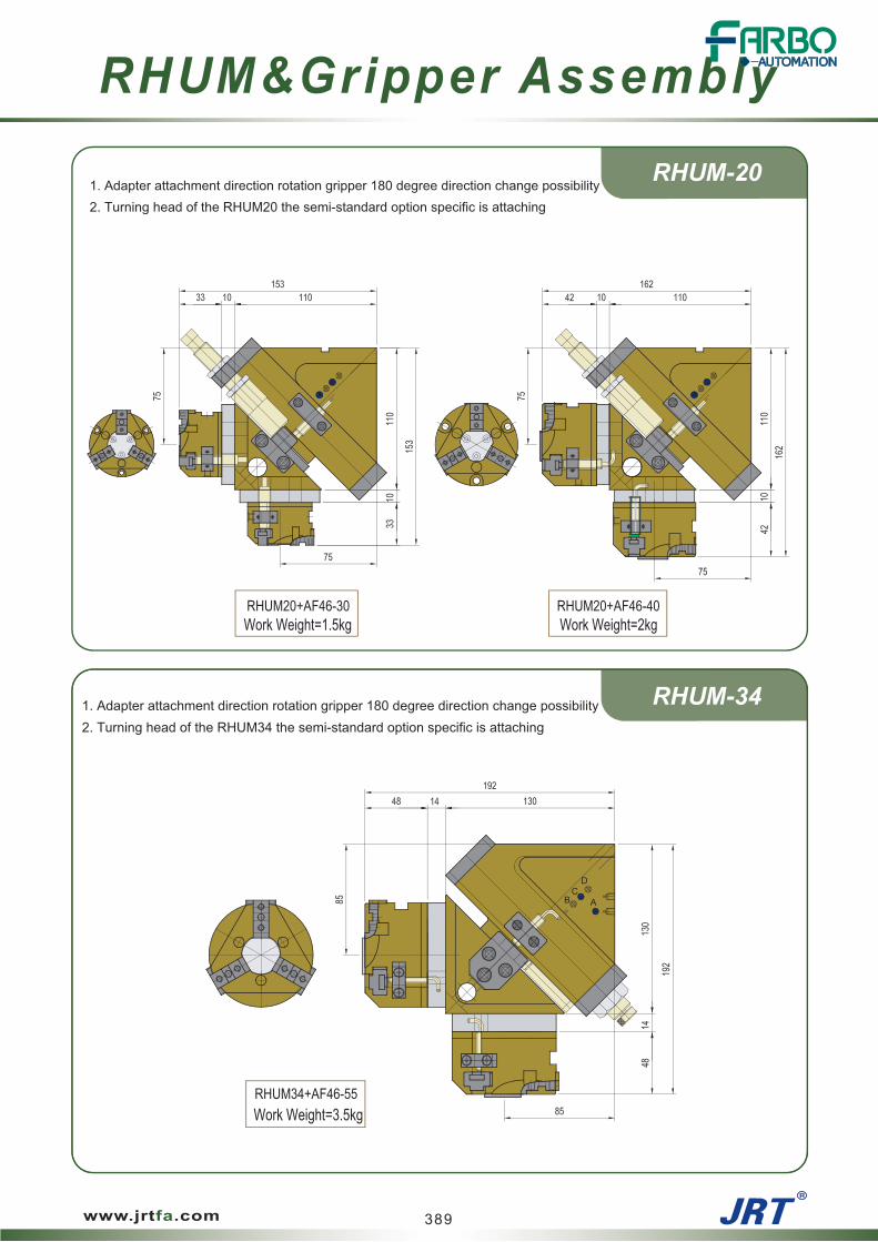
1. Adapter attachment direction rotation gripper 180 degree direction change possibility2. Turning head of the RHUM20 the semi-standard option specific is attaching
Work Weight=1.5kg Work Weight=2kg
CB A
D
1. Adapter attachment direction rotation gripper 180 degree direction change possibility2. Turning head of the RHUM34 the semi-standard option specific is attaching
Work Weight=3.5kg
RHUM20+AF46-30 RHUM20+AF46-40
RHUM34+AF46-55
389
RHUM&Gripper Assembly
www.jrtfa.com

RHUM-40
RHUM-40N
1. Adapter attachment direction rotation gripper 180 degree direction change possibility2. Turning head of the RHUM40 the semi-standard option specific is attaching
Work Weight=5kg
1. Adapter attachment direction rotation gripper 180 degree direction change possibility2. Turning head of the RHUM40N the semi-standard option specific is attaching
Work Weight=8kg
RHUM40+AF46-75
RHUM40N+AF46-95
390
RHUM&Gripper Assembly
www.jrtfa.com

Notes
www.jrtfa.com 391

Special Cylinder
www.jrtfa.com
Supply Device
Pick & place uni tJPP (Finger Attachable)
RSS, RSD (Ant i -Rotat ionable)
RK (Miniature Pushing)
RTJ (Air Rotat ion Supply Device)
Separator
Knock Cyl inder
394
398
404
408
394
398
404
408
392

Special Cylinder
www.jrtfa.com
Pick & Place Unit
Separator
Knock Cyl inder
Supply Device
6.5
6.5
Payload(kg) Weight(kg) PagePractical Torque
(Nm)Stroke(mm)Type
50
0.32P
0.32P
0.8
0.8
30JPP11
JPP11
RSS-20
RSS-20
182.5
182.5
117.7
117.7
30~200
30~200
10 30~200
0.31
0.49
0.58
Theoretical Power(N) Weight(kg) Page
30~200
0.2210
20
Speed( mm/sec) Forward
RSD-20 20
Type
RSD-12
Backward
117.7
53.6 29.4
182.5
34.1
16
16
16
117.7
117.7
117.7
88.3
88.3
88.3
10
10
10
45.9
45.9
45.9
TypeTheoretical thrust (N)
Weight (kg) Page
5 0.082
10 0.094
15 0.106
5
34.1
0.128
0.160
0.142
15
10
Forward Backward
34.1
0.44
Weight (kg)Theoretical thrust (N)
Type Page
50
Backward
1.470S
Forward
JPP Finger AttachableJPP Finger Attachable
RSS, RSD Anti-Rotat ionableRSS, RSD Anti-Rotat ionable
RK Miniature PushingRK Miniature Pushing
RTJ Air Rotat ion Supply DeviceRTJ Air Rotat ion Supply Device
Stroke(mm)
Stroke(mm)
Stroke(mm)
394
398
404
408
P=Air Pressure[bar]
393
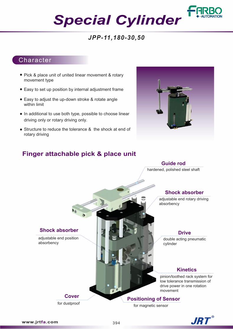
Pick & place unit of united linear movement & rotarymovement type
Easy to set up position by internal adjustment frame
Easy to adjust the up-down stroke & rotate anglewithin limit
In additional to use both type, possible to choose lineardriving only or rotary driving only.
Structure to reduce the tolerance & the shock at end ofrotary driving
Guide rodhardened, polished steel shaft
Kinetics
Shock absorber
Cover
adjustable end positionabsorbency
for dustproof
adjustable end rotary drivingabsorbency
JPP-11,180-30,50
Finger attachable pick & place unit
www.jrtfa.com
pinion/toothed rack system forlow tolerance transmission ofdrive power in one rotationmovement
Drive
Positioning of Sensor
double acting pneumaticcylinder
for magnetic sensor
Shock absorber
394
Character
Special Cylinder

JPP
Exploded view
Bearing CoverBal l Bear ing
Back Cover(B)
Back Cover(A)
Bevel Gear(A)
Rotary Plate
Bal l Bear ing
Rod Holder
Guide Rod
Guide Holder
Du-Bush
Upper Plate
Spl ine Shaft
Holder
Support Rod
Post
Cover Plate
Cyl inder Head Cover
Piston Rod
Piston Packing
Piston Rack
Piston Packing
Plast ic Magnet
Wear Ring
Main Body
Base Plate
Piston
www.jrtfa.com
Snap ring
L.M Bearing
Bevel Gear(B)
Driv ing Gear
Bearing Cover
Bear ing
Cyl inder Body
Bearing Cover
395

Product Name JPP11
Rotating Angle 90 , 180
Up-down Stroke 30 (30mm), 50 (50mm)
Sensor Type RS or Nomark
Sensor Quantity
Speci f icat ion
Order ing Code
JPP
www.jrtfa.com
JPP11 180 30 RS 2
* See the sensor specification of 2D dimension drawing
396
JPP11-30 JPP11-50
P=Air Pressure[bar]
Unit
Max. PayLoad Kg
degree
mm
Kg
sec
sec
Cm3
degree
bar
Radius of Rotation
Up/Down Stroke
Weight
Turning Time ( 90 )
Turning Time (180 )
Fitting size
Air consumption(90 /180 )
Repetition Accuracy
Operating pressure
Ambient temperature
Lubrication
Products Name
-5 to 60
Needless
3 to 7
±0.1
Cushion Stopper or Absorber
0.8
75 to 200
PF(G) 1/8
52.9 / 79.8
1 to 3
1 to 2
0.8
75 to 200
PF(G) 1/8
70.3 / 97.2
1 to 3
1 to 2
30 50
6.5 6.5
* After 100 consecutive strokes to end positions

2-PF(G)1/8 AIR PORTUP/DOWN
REED SWITCHJRTM
2x2-M14x1.5pSHOCK ABSORBER
JPP-11
JPP
www.jrtfa.com
2-PF(G)1/8 AIR PORTTURN
397

Rodnon-turn piston rod
RSS-20 / RSD-12,20
Anti-rotationable separator
www.jrtfa.com
Positioning of Sensor
Drivedouble acting pneumaticcylinder
for magnetic sensor
Linear actuator of non-turn piston rod type
Suitable to separate workpiece by mounting in paralleltwo cylinder
In case of individual using, it's suitable to push workpiece
Bodyhigh-tensile aluminum body withlightest possible because ofhard anodizing
398
Character
Special Cylinder

RSS/RSD
Exploded view
Back Cover
Snap Ring
Piston Packing
Cyl inder Body
Damper Ring
O-Ring
www.jrtfa.com
Wear Ring
Gusset Plate
Front Cover
Magnet
Magnet Bracket
Piston Rod
399

Speci f icat ion
Order ing Code
RSS/RSD
www.jrtfa.com
RSS 20 10 RS 2
* See the sensor specification of 2D dimension drawing
Product Name RSS, RSD
Bore Size 12, 20
Stroke 10, 20
Sensor Type RS or Nomark
Sensor Quantity
400
-5 to 60
Needless
3 to 7
±0.1
RSS20
P=Air Pressure[bar]
Unit
Decided stroke mm
N
N
mm/sec
mm/sec
Kg
Cm3
mm
bar
Push Power
Pull Power
Max. Speed
Min. Speed
Weight
Fitting size
Air consumption quantity
Repetition Accuracy
Operating pressure
Ambient temperature
Lubrication
Products Name
10/20
30.41P
0.103xSt
M5
0.22/0.31
30
19.62P
200
RSD20
10/20
30.41P
0.103xSt
M5
0.49/0.58
30
19.62P
200
RSD12
20
8.93P
0.035xSt
M5
0.18
30
4.91P
200
* After 100 consecutive strokes to end positions

RSS-20
RSD-20
RSS/RSD
www.jrtfa.com
FOR SENSOR HOLE
FRONT SIDE VIEW BACK SIDE VIEW
STROKE+15
STROKE+5.5
2xSTROKE+52
2xSTROKE+38
2-M5 AIR PORT
2x2-M5 AIR PORTFOR SENSOR HOLE
STROKE+5.5
2xSTROKE+38STROKE+25
2xSTROKE+59
STROKE+15
401

RSD-12
RSS / RSD
www.jrtfa.com
189
(Opposite Side)
REEDSWITCH(JRT-02)
Note
2-M5 AIR PORT
402

Notes
www.jrtfa.com 403

Linear actuator of compact type for push theworkpiece (Knock cylinder)
Easy to mount at plate by screwing body
Sensor is not available for this type
RodCompact type for push the workpiece
RK-10,16
Miniature pushing cylinder
www.jrtfa.com
Cylinder bodyDrivedouble acting pneumaticcylinder
easy to mount at plate byscrewing body
404
Character
Special Cylinder

Piston Packing
RK
Exploded view
Lock Nut
Rod Packing
Cyl inder Body
Cyl inder Head Cover
O-Ring
Piston Rod
www.jrtfa.com
Lock Nut
405

Product Name RK
Bore Size 10, 16
Stroke 5, 10, 15
Sensor Type BS or Nomark
Sensor Quantity
Speci f icat ion
Order ing Code
RK
www.jrtfa.com
RK 10 10 BS 2
406
P=Air Pressure[bar]
Unit
Decided stroke
Weight
Push Power
Pull Power
Fitting size
Air consumption quantity
Actuating Method
Repetition Accuracy
Operating pressure
Ambient temperature
Lubrication
Products Name RK10 RK16
N.m
g
N
N
Cm3
mm
bar
5
82
-5 to 60
Needless
3 to 7
±0.1
10
94
0.014xSt
M5
7.65P
5.69P
15
106
5
128
10
142
0.035xSt
M5
19.62P
14.72P
15
160
Double action type
* After 100 consecutive strokes to end positions

RK-10
RK-16
RK
www.jrtfa.com
10
27
20
29.55
10
5 M22 x p1.5(THREAD)M4 x p0.7
2xSTROKE+31.5
12
STROKE+19.5ST+12
STROKE+13.5 6
18.5
2-M5 (AIR PORT)
M26 x p1.5 Thread6
12
14
STROKE+14 STROKE+20.5
STROKE+14.5 6
23
3224
2-M5 (AIR PORT)
3516
2xSTROKE+34.5
8
M5 x p0.8
407

Character
Fixingby fit, thread and lock nut
RTJ-50,70
Special Cylinder
Air rotation supply device
www.jrtfa.com
Air outletfor connection to applicationspecific to be produced bythe customer
Pneumatic intakefor air distribution
Bodyhigh-tensile aluminum body withlightest possible because ofhard anodizing
Protector to prevent the tangle of the air supply tube anddistributor to supply power at rotating movement
Admissible RPM is below the 100
Additional bearing is unnecessary by internal ball bearing,when gripper mount.
RTJ is not a rotary actuator
408

RTJ
Exploded view
Driving Shaft
Quad Ring
Housing
Bal l Bear ing
www.jrtfa.com
Lock Nut
Bal l Bear ing
Lock Washer
409

Speci f icat ion
Order ing Code
RTJ
www.jrtfa.com
RTJ 50
P=Air Pressure[bar]
Product name RTJ50 RTJ70S Unit
Weight 0.44 1.46 kg
Fitting size 2x2-M5 2-M5(Rev.),2-PF(G) 1/8(Fix.)
Max. Payload 2.4 4 kg
Max. Revolution rpm
Operating pressure
Ambient temperature
Lubrication
100
3 to 7
-5 to 60
Needless
Product Name RTJ
Bore Size 50, 70S
bar
410

RTJ-50
RTJ-70S
RTJ
www.jrtfa.com
2-M5 AIR PORT
2-M5 ROTATE AIR CONNECTION
2-PF(G)1/8 AIR PORTFIXING
2-M5 AIR PORTFIXING
411

www.jrtfa.com
Magnet ic switch (sensor) order ing code
Sensor
JRTM R 3M EX
None : Standard type
EX : Flame-proof type
None : Cable length = 1m
3M : Cable length = 3m
5M : Cable length = 5m
QD8 : M8-3p male quick connector(Cable length is 0.15m)
R : Reed switch 2 wire type
N : Solid state type,current sinking
P : Solid state type,current sourcing
RT : High temperature type (125 )
Product Name JRTM, JRT-02, JRT-03, JRT-34
Cable Length
Ex Mark
Sensor type
Magnetic Sensor & Proximity Switch
Proximity switch(sensor) order ing code
None : Cable length is 1M (Standard)
3M : Cable length is 3M
None:Solid state NPN type,current sinking (3 wire)
P : Solid state PNP type,current sourcing (3 wire)
Product Name JPM8,JPM8S,JPM12
Cable Length
Sensor type
JPM8S P 3M
412

Magnetic Sensor
www.jrtfa.com
Magnet ic Sensor Speci f icat ionCHARACTERISTIC TYPE Reed Switch NPN Type PNP Type
Switching Logic SPST Normaliy Open
Sensor Type Reed Switch NPN Current Sourcing PNP Current Sourcing
JRTM, JRT-025 to 120V DC/AC
JRT-03, 345 to 240V DC/AC
Switching Current 100mA max.
Switching Rating 5 W max.
Voltage Drop 2.5V max.@40mA to 100mA DC
Leakage Current -
Current Consumtion ----- 15 to 20 mA max. 16 to 18 mA max.
Indicator Red LED Red LED Green LED
2C,Oil Resisdent PVC
JRTM PU
Max. Switching Frequency 200 Hz
Temperature Range
Shock -Note 2. 30G
Vibration -Note 3.
Insulation Resistance
Dielectric Strength
Enclosure Classification
Protection Circuit None
CE Certificate No. No. E8 04 07 53334 001 No. E8 04 07 53334 003 No. E8 04 07 53334 002
3C Certificate No. No.:2004010305127433
CNEx Certificate No. CNEx05. 1366X(ExnCllCT6)
Reed Switch NPN Type PNP Type
Note
1. The max. operating voltage of T- R-QD8 is 60V AC/DC (Based on IEC61076-2-101).
2. Sin Wave / X Y Z 3 Directions /3 Times Each Direction / 11mS Each Time.
3. Double Amplitude 1.5mm / 10Hz~55Hz to10Hz(Sweep 1min) / X Y Z
3 Directions / 1Hour Each Time.
4. Measuring standard target: 15.5 x 8 x 5t(Anisotropic Rubber Magnet).
5. We reserve the right to make changes without notice.
Solid State Output,Normally Open
Connect Diagram
-10 to 70
100M (Measured by 500V DC Mega between Lead to Case)
9G
1.5 V max.@ 200mA DC(Resistive Load)
0.01 mA max.
3C,Oil Resisdent PVC
Operating Voltage-Note 1.
1000 Hz
Cable
CNEx05. 0842 (ExiallBT6)
-
5 to 28V DC
200mA max.
20 W max.
1500V AC rms for 1 minute or 1800V DC rms for 1second(Lead to Case)
IP 67 (NEMA 6)
Power Source Reverse Polarrity;Surge Suppression
50G
Power
(Reed Switch Type)
Brown
Blue
LoadPower
(Solid State NPN Type)Blue
Black
Brown
CIRCUIT
MAIN Load
(Solid State PNP Type)
MAIN
CIRCUIT
Black
Blue
Brown
LoadPower
413

SENSOR
www.jrtfa.com
~
JRTM
JRT-03
JRT-02
JRT-34
Proximity Sensor
3
96.5
6.9
to
to
to
414

QUICK CONNECTORNote. The dimensions of plast ic which with cable is for reference
www.jrtfa.com
<< Connector >>
<< SENSOR >>Standard Cable
type
3 wire QD wiring
M83F (Female)
M8 WIRING
Connector type QD8
Speci f icat ion
Characteristic
Connector Type M8 3PIN Female (Straight)
Lead Wire Color PIN 1:Brown, PIN 3:Blue, PIN 4:Black
Max. Operating Voltage 60V AC/DC
Max. Rating Current 3A
Insulation Between Contacts 1.0KV
Insulation Between Contacts& Metal Housing 0.85KV
Pin Coating 5 M GOLD COATING
Numbers Of MechanicalOperations Over 100 times
Temperature Range -25 to 85
Cable Tension Forcein Connected 30 N
IP Degree Protection IP 67 (IEC 60529)
Standard IEC 61076-2-101
M83FType
415

SENSOR
www.jrtfa.com
M8 Connector Dimension
Particular attention must be paid not to exceed the limits list in the specification.
Otherwise, permanent damage to sensor may occur.
1. For reed switch type sensors, it must be series connected a LoAD to use, or will damage the sensor.
2. Connect the brown wire in series with LOAD to pesitive(+) and the blue wire to negative(-) of power source.
If the polarity be inverted, reed switch remains functional but LED will remain in "OFF" state.
Just exchange the brown and blue wires.
1. For solid-state type sensors, it must be used with DC power source.
2. Connect brown wire to pesitive(+) and the blue wire to negative(-) of DC power source.
The black wire must be connected to the LOAD only.
3. If the black wire is connected to the power source directly. permament damage to the sensor may occur.
1. The external protect element is required.
If the sensor is used to switch conductive load. such as relay or solenoid valve.
2. For DC conductive load. attach an external diode parallel to the load as illustrated below.
3. For AC conductive load. use R-C circuit to parallel the load as illustrated below.
If the sensor is used to switch capacitlve load or the cable length exceed 10M.
Please series a inductor (470 H ~ 2000 H) as close to the sensor to prevent damage (sticking effect).
Keep sensor out of the strong magnetic field to get rid of interference.
2 Wire standard connection
3 Wire standard connection
Inductive load protection
Capacitive load protection
Power
(Reed Switch Type)
Brown
Blue
Load
(Solid State PNP Type)
MAIN
CIRCUIT
Black
Blue
Brown
LoadPowerPower
(Solid State NPN Type)Blue
Black
Brown
CIRCUIT
MAIN Load
(Application to DC Conductive Load)
SWITCH
Blue
BrownLoad
(Application to AC Conductive Load)
SWITCH Brown
Blue
Load
Inductance is about 470H ~ 2000H
Load
10M or more
Blue
SWITCH Brown
Inductor
416

The safety issues enumerated here are to prevent damages by directing customers to use the productsappropriately. The issues have been classified into "caution," "warning," and "danger" in order toindicate the degree and urgency of damages.
[Warning] Events in which people could die or become severely wounded when products are mishandled.
[Danger] Urgent events in which people could die or incur severe wounds.
[Caution] Events in which it is expected that people will become injured or that only materials will be
Please remember the following before use.
damaged when products are mishandled.
Warning
Because the products registered on the catalogue were designed to be used with pressurized airsystems, do not use the products off the specified pressure or temperature levels. It could be thereason of destruction or malfunctioning.
Remove debris within the pipe by air blowing (flushing) or washing before piping.Pressurized air that contains abundance of moisture could cause damages toair pressurized machines.
Use after removing moisture with an air dryer or drain catch.
When compressed air contains synthetic oil, salt, and corrosive gas, use clean air to prevent destructionor malfunctioning.
Do not use the product in places where the product could be subject to vibration or impact.
Do not disassemble or modify the main body. However, if it becomes necessary to disassemble theproduct to fix it, turn off the power, intercept the pressure and exhaust the pressurized air.
417
Safety
www.jrtfa.com

Safety
www.jrtfa.com
- General precautions when using pneumatic products
* Appropriate pressure
Pneumatic products' pressure should be between 3 to 7 for them to operate normally.When the product is used under a low pressure (under 3bar ), the operation (especially of the slidecylinder) could be defective. In the case of a rotary cylinder or a rotary unit, there is a possibility thatthe parts related to the attached absorber could not function well.When the pressure is high (more than 7bar), the product could be damaged or its life could be shortened.For large products, high pressure could cause unexpected accidents. Especially, when the pressure isgreater than 10bar, it would be a violation of the regulations on high pressure.
* Appropriate temperatures
The appropriate temperature range is from 5 to 60 . Make sure that the outside temperature doesn'texceed 60 because under the temperature of 5 the moisture contained in the air and over thetemperature of 60 , the problem with the NBR packing (although the packing can withstand up to100 , partial temperature rise could take place) could occur. Also, because the coefficients of heatexpansion of various materials used in products are different, jams could occur during operations.Furthermore, air leakages and cracks in parts could occur. Therefore, consult us before using pneumaticproducts under continuous high temperature or low temperature or under the condition in which hightemperature and low temperature states are repeated.Even for a single product, diverse packings are used for producers. Also, due to the fact that not everyheat-resistant packing has been developed, when supply problems occur (delivery date, price, andinventory),available packings.
* Appropriate speed
Because the speed of pneumatic cylinders is affected by the built-in packings, you can use them under thespeed of from 50mm/sec to 500mm/sec. Under low speed, uneven operations such as the stick slip couldoccur and under high speed, life of the packing could be compromised substantially, resulting in the leakageof air. Therefore, consult us before using the equipment under high speed.
* Product life
There is a regulation in a foreign country that stipulates that a cylinder should be able to withstand damagesto its pistons after working distance 300km. When the movement of the cylinder with the stroke of 150mm iscalculated, movement of about 1 million is guaranteed. Air finger products are subject to load caused by thegripping of the product.Also, the product is located at the hem of general cylinders, thereby being exposed to oil, chips, andpolishing stone powders. As a result, the life is reduced to 1/4 that of a general cylinder.Our warranty period for our products is 1 million operations or 1 year, whichever comes first. For productsthat exceed the above criteria, we provide product services by charging for only parts and services. However,the service cost could increase for those products that have been around for more than 5 years or for thoseproducts that are no longer being produced. In such cases, we recommend that you replace your productwith a product of identical specifications.
beware that product specifications could change because products are designed based on the
418

* About the specifications of optional products
In the event that producers are out of business, or foreign products are out of stock, it becomes impossible tocheck the specifications, or when there aren't any appropriate products, the company tries to resolve theproblems with products that meet the users' specifications. As of 2004, the company had produced andsupplied more than 2,000 optional products, retaining blueprints and data. However, due to the uniquecharacteristics of optional products, exorbitant costs and time could be consumed compared to standardproducts because of extraordinary amount of preparations (including designing), production of tools and toolsetting, and program modifications. Also, standard products are stable because they are backed by tests asa result of 17 years of experience in production and because of the use of standard parts. However, optionalproducts could be of lower quality due to the fact that products are produced according to limitedspecifications. When ordering optional products, remember that price increases, late deliveries, and qualitydeteriorations could result. Also, when producing optional products, the RS specifications are designed andproduced based on the sensor types used by us. When you wish to use your own sensor, please provide uswith the sensor and mounting parts beforehand. If you need to custom design a product, we will produce theproduct according to your specifications.
* Caution when using replacement parts
Some users purchase parts without ordering from us separately.- When you make an order without indicating the RS, parts related to the sensor (magnet and parts attachedto the sensor) are not provided. When you order separately later on, a higher price will be charged. Also,we are not liable for problems that occur due to the use of a sensor attached arbitrarily. During the warrantyperiod, product services will be provided.- When you order without indicating the PS, the parts related to the adjacent sensor (sensor dock andsensor bracket) are not provided.When you order the parts separately later on, higher prices will be charged. Also, the problems could occurdue to the sensitivity, length, and thickness- When ordering without indicating the DA, the parts related to the shock absorber (buckling protector,spacer ring, and others) are not provided.Do not change or attach the oil pressure shock absorber that are attached to the rotary cylinder or rotaryunit arbitrarily. The parts related to the shock absorber have been designed and produced by consideringcomprehensively the rod, stroke, length, shape of screws, and impact absorption energy. As a result, whenspecifications change, many problems could occur. Before attaching or changing the shock absorber, makean inquiry to us and attach the product with identical specifications.- The air pipe speed controller or one-touch fitting parts were designed based on the products that could bepurchased in the marketplace. Because damages and mutual interruptions could occur, inquire us beforeusing products with special specifications (PF types, check valves, and inch types)
* Problems associated with additional processing
Additional processing to the existing parts including the standard pin part of the finger adapter rotaryunits (RHU + finger assembly), addition of the bottom side of the AF 56N and air port, the BF optionof the AF 30 & AF 46 type (addition of the air port at the bottom) and additional processing to theexisting parts (especially on the standard pin), addition of the standard part and air port on the bottomof the AF 56N, and the BP option on the AF 30 & AF 46 type (addition of the air port on the bottom)are delivered without additional post-processing. When hard anodizing is performed, changes tothe common difference occur. Therefore, take note that products are delivered in the processed state.
* About unannounced specification changes
Because products and their functions improve continuously, changes to the interior and exterior could takeplace. We do our best to keep the specifications listed on the catalogue in order to keep our promise withour customers. However, changes could occur inevitably in order to enhance the quality. When an existingproduct is eliminated and replaced by an improved product, the changes could take place without priornotice in the case that 100% compatibility is assured. In such a case, no prior notification takes place.Material changes, color changes, and specification changes of some sensors could change without priornotification. However, when problems with product usage are foreseen due to the changes in the locationof the mounting tap and in the shape as well as administrative changes, changes of products' names takeplace or notifications are made when ordered.
419
Safety
www.jrtfa.com

- Caution when using Gripper types
* Caution when using the sensor
1) Under the environment in which the sequence control is required due to the use of the magnetic sensor,we produce and sell RS type products except for small products. Also, most products have built-in magnets.
2) When fully assembled products are shipped, it is checked whether the sensor operates properly.However, when products are used onsite, defective sensors could be discovered.There could be many different factors,but one of the causes could be the transmission of magnetic force through the mounting bolt that goesthrough the body and through the plate attached to the product. When a problem occurs, use bolts made ofstainless materials and change the material of the mounting plate with aluminum.
3) For some small products, iron magnets of the Nd-Fe type have been built-in. Due to the material'scharacteristics, the magnetic power decreases drastically under high temperatures (greater than 50degrees).Therefore, caution is required when using a product under high temperature.
4) For small products, there is a possibility that the sensor could protrude under the body. Generally, theextrusion is indicated on every product, but changes in the extrusion length could change due to thestate of the induction of the sensor. Therefore, when selecting a small product, be sure to obtain sufficient
* Caution about the center of the axis
When gripping an object while the object has been fixed, be careful about the center of the axis.Wedge type products such as the AF 30, AF 46, and AF 56N are structurally weak against eccentricity.When supporting equipments are not used, either the jaw could stop operating or damages to the plungercould occur.
* Caution about the gripping power of the finger
1) The gripping power of the finger could be broadly classified into general and disassembly types.
- The general type could be indicated as thrust x operational thrust x efficiency.Thrust = value derived by multiplying the cross section of the piston by air pressure and operational
coefficient = the transportational distance of the piston / operational distance of a jaw, and the efficiency= 0.8. For the constant including the operational coefficient and variables, inquire us. We plan to documentour data and distribute them in the nearest future.- The disassembly method is the method of analysis that incorporates the structural interpretation of variousoperational powers, frictional coefficient, lubrication coefficient, and gear efficiency. The method is toocomplicated for a general user to use and changes to the value could occur due to various coefficients andvariable values. We are in the process of developing a program. Also, we have come up with methods ofcalculating the wedge type, rack & pinion type, angular open and close type air fingers, drooping of the slidecylinder, and the appropriate load of the rotary cylinder, and are currently distributing the calculationmethods
2) In order to check the operational state of the air finger of the parallel open and close method, the machineis usually opened and the jaw is operated manually. However, according to 1) above, when the operationaldistance of the piston is great and the operational distance of the jaw is relatively small, the thrust generatedby air pressure is great and the quality is relatively defective when operated manually. That's because thepiston has to be moved a lot by operating the jaw just a little. Therefore, due to the structure of the air finger,it's not correct to change the operational direction of the piston by using a medium, especially for wedgetype products.
420
Safety
www.jrtfa.com

3) For angular open and close type air finger products, the distance between the center of the product andthe hinge point (the rotational center of the jaw) is short, the gripping power is substantially lower compared tothe diameter of the piston. Therefore, refer to the specifications of the catalogue.
4) The factor that decreases the product's gripping power and its durability the most is the distance betweenthe finger body and the operational point. As the operational distance increases, a bending momentumoccurs, increasing the friction on the sliding of the jaw drastically, resulting in the damages to the jaw, wearand tear of the sliding, and expansion of the body. Therefore, set the operational distance as short as possible.
5) Generally, the durability and thrust of the finger isn't proportional according to the differences in theweights of the objects.For example, when light objects such as a ping pong ball or an iron ball of identical volume are gripped, theforce that acts on the jaw is identical and the differences in the effects on the durability of the jaw areminuscule. Even when very light objects are gripped, please be careful about the distance of the operationpoint indicated in 4).
* Production of Normally Open and Normally Close
These days, orders for red brass products with built-in springs that maintain the normally open and normallyclose states under the atmospheric pressure are on the rise. The major uses for red brass products are asfollows:
1) To prevent the drooping of objects and collision while moving by maintaining the standard state when airis intercepted
2) To supplement insufficient thrust when opening or closing
3) To save on air and electricity for operating the solenoid, and to realize fast response with the spring byusing only the spring without using an air portRestitution of the compressed spring = Spring coefficient x Displacement (Compression length)Here, the spring coefficient is reduced inversely with the length under the identical condition.When classifications are made by the Length of the repulsive force “0”> Required minimum repulsiveforce> Required maximum repulsive force> Allowed change in length> and Contact length,only to or to are applied to products. Here, the length of the product is stretched by the length ofthe [ or - existing spare space].
Therefore, when ordering normally open and normally close products, be careful of the fact that the product'slength increases. Especially, when the maintenance of a constant repulsive force is required, take note thatthe product's length could increase further because specifications with low spring coefficients (relatively longlength) are required in order to ensure that changes in the repulsive force according to displacement arereduced.
* When using the product in places where impure materials could infiltrate
1) Refrain from using cross roller type products such as the AF 216 or LMT. When dusts and other impurematerials infiltrate the roller, the rotation of the roller is obstructed. When they stick to the roller, the guideson both sides are stretched to the lateral directions, causing defects and making it impossible to use theproduct.
2) When the product is applied to polishing processes, resulting in the infiltration of polishing dusts, refrainfrom using products whose aluminum bodies become subject to friction by the jaw such as the AF 30 andAF 46 types, if possible. If such products have to be used, consult us before use. Polishing stone dustsinfiltrate into the side of the jaw that's subject to friction, acting as the body's abrasive material to decreasethe life of the product drastically.
3) In most cases, foreign materials infiltrate inside products through existing niches (especially the spot onwhich the close sensor dock is placed). Request us to close up unnecessary space
.
4) Add the air blowing (flushing) mechanism that supplies compressed air into the product periodically andexhausts the air to prevent the infiltration of impure materials.
421
Safety
www.jrtfa.com

5) Scraper seals and other equipment should be added in order to prevent the infiltration of foreign materialsinside the cylinder. In order to save space in the air finger, the scraper seal is absent on our products andother companies' products.
6) Review products that are used for attaching cover such as the AF 13C and AF 22C beforehand.
7) Due to the requirements of lean production and order specifications, we have not been able to meet thedemand of the javarar (anti-dust cover made from rubber). We will do our best to produce products thatcould augment it.
* Caution when using the key home
Most of slide cylinder bodies are produced with extruding and impression materials because themeasurements (including the common difference) indicated on the blueprint cannot be satisfied in themanufacturing process. As a result, extruding and impression processes are undergone. Some partsexcluding main parts could be completed in the impression state that's less than the measurementindicated on the blueprint. When you wish to use the key way indicated in the blueprint, notify uswhen ordering.
* Use of the maximum values of the stroke and the median administration
1) The minimum administration indicated on the specifications of the slide cylinder is the minimum value forthe production of products, and the value below 1mm is possible. However, for the RH, SC, TL, and otherproducts, the air cushion function is lost. Also, most products cannot use 2 sensors.
2) When the maximum administration is exceeded, the GS and SC that use the cylinders sold in the marketdepend on the possibility of the production of the cylinder. However, with the changes according to theelongation of the impression body, the operations become defective, with the occurrence of excessivedrooping for the GC, SC, and others. For the RH (W) 20, NO, NF, and JO that manufacture the slide shaft,the difficulty of production is enormous, resulting in higher prices, late deliveries, and other problems.Therefore, care should be taken.
3) For the median administration, when the unit that's below the decimal point is demanded (eg: 31.2),select an upper administration (eg: 32) and adjust minuscule amounts by using the basic stopper.
* Allowable load of the rotary cylinder
In our catalogue, the allowed trust of the rotary cylinder and radial load are set low. Generally, the rotarycylinder's life and function are determined by the amount of impact caused by the inertial momentum.This inertial momentum is proportional to the weight x distance2, and is affected more by the distance fromthe center than by weight. Set the distance from the center at the minimum.
Many users select products with the weight in mind. Therefore, the allowable weight was recorded low bypredicting the distance to the object for general use.
* Optimal use of the rotary cylinder
1) Locate the object to the place closest to the center of rotation of the rotary cylinder.
2) Lighten the weight of the load such as the adapter plate and bracket.
3) When subject to lopsided load (especially in the direction of perpendicular gravity), attach a balancingweight (FMF) to balance the weight on both sides. When there is a change in the load due to loading andunloading, attach a balancing weight that's close to the median value of the maximum and minimum load(layered structure for adding or subtracting weight) for test purposes so that you may use the product underthe optimal condition.
422
Safety
www.jrtfa.com

* The Real Stopping System of the Rotary Cylinder
For rotary cylinders with a double power structure (in which thrusts occur simultaneously on both cylinders)such as the SDRJ and RHU, we encounter customers' opinions that the exteriors of our products are inferiorto those of other companies that are simpler.That's due to the difference in structure. Our products are based on the stoppage structure in which the turntable is stopped. As a result, the stoppage power is equal to the rotational power (2x). In contrast, theproducts that stop pistons inside have stoppage power that is reduced by half relative to the rotational power(2x). We will provide answers to questions when you ask for structures and principles. Compare ourproductswith other products onsite while air has been supplied and the products are not operating (especially in theperpendicular direction). Sleekness of the exterior cannot take precedence over function.
423
Safety
www.jrtfa.com

Notes
www.jrtfa.com 424

BIBUS locations - network of competencies
Headquarters and SwitzerlandBIBUS AGAllmendstrasse 26CH-8320 FehraltorfTel. +41 44 877 50 11Fax +41 44 877 50 19E-mail: [email protected]
AustriaBIBUS Austria GmbHEduard Klinger-Strasse 12AT-3423 St. Andrä-WördernTel. +43 2242 33 388Fax +43 2242 33 388 10E-mail: [email protected]
BelarusBIBUS (BY) COOO8th Per. Ilyicha 13a, office 2.1BY-246013 GomelTel. +375 232 37 10 01Fax +375 232 37 10 01E-mail: [email protected]
BulgariaBIBUS Bulgaria Ltd.Lulin Plaza, Office 3A5 Dobri Nemirov Str.BG-1324 SofiaTel. +359 885 494 275Fax +359 292 732 64E-mail: [email protected]
CroatiaBIBUS Zagreb d.o.o.Anina 91HR-10000 ZagrebTel. +385 1 381 80 04Fax +385 1 381 80 05E-mail: [email protected]
Czech RepublicBIBUS s.r.o.Videnska 125CZ-639 27 BrnoTel. +420 5 47 125 300Fax +420 5 47 125 310E-mail: [email protected]
DenmarkA/S H. SINDBY & CoBommerhavevej 41, SleldeDK-7100 VejleTel. +45 75 88 21 22Fax +45 75 88 22 40E-mail: [email protected]
FranceBIBUS France S.A.S.ZI du Chapotin85, Avenue Marius BerlietFR-69970 ChaponnayTel. +33 4 7896 80 00Fax +33 4 7896 80 01E-mail: [email protected]
GermanyBIBUS GmbHLise-Meitner-Ring 13DE-89231 Neu-UlmTel. +49 731 20 76 90Fax +49 731 20 76 96 20E-mail: [email protected]
Great BritainBIBUS (UK) Ltd20 Soho MillsGB-Wooburn Green HP10 0PFTel. +44 1628 533 300Fax +44 1628 533 377E-mail: [email protected]
HungaryBIBUS KftUjhegyi ut 2HU-1103 BudapestTel. +36 1 265 27 33Fax +36 1 264 89 00E-mail: [email protected]
PolandBIBUS MENOS Sp. z o.o.ul. Tadeusza Wendy 7/9PL-81-341 GdyniaTel. +48 58 660 95 70Fax +48 58 661 71 32E-mail: [email protected]
RomaniaBIBUS SES SRLPestalozzi Street 22RO-300155 TimisoaraTel. +40 256 200 500Fax +40 256 220 666E-mail: [email protected]
RussiaBIBUS o.o.o.Izmailovsky prospect 2ARU-190005 St. PetersburgTel. +7 812 251 62 71Fax +7 812 251 90 14E-mail: [email protected]
SlovakiaBIBUS SK s.r.o.Priemyselná 4SK-949 01 NitraTel. +421 37 741 25 25Fax +421 37 651 67 01E-mail: [email protected]
SloveniaINOTEH d.o.o.Ruska cesta 34SI-2345 Bistrica ob DraviTel. +386 2 665 11 31Fax +386 2 665 20 81E-mail: [email protected]
UkrainaBIBUS Ukraine TOVUl. Mashinobudivnykiv 5aUA-08162 Chabany, Kyiv regionTel. +380 44 545 44 04Fax +380 44 545 54 83E-mail: [email protected]