Catalogo Overview R5 - Fanox
36
PRODUCTS OVERVIEW Expertise in Protection Relays
Transcript of Catalogo Overview R5 - Fanox

PRODUCTS OVERVIEW
Expertise in Protection Relays
Fanox is a company specialised in the design and manufacture of Electronic Relays for Low and Medium Voltage applications. Since its foundation, back in 1992, Fanox has developed a wide range of products for multiple applications, and as an innovation driver and trendsetter, is settling itself in the energy market as a powerful manufacturer of a large number of Protection Relays that can be used in any kind of application in the Transmission & Distribution Lines.
Fanox Relays has become the safest and most reliable Relays on the market. All our Relays can be adapted to the technical specifications and requirements of customers, obtaining the best technical solution to meet their application and assembly needs.Our expertise and in-house R+D+i in continuous development and innovation enables us to offer global and complete solutions to each specific application.Since protection devices have changed so much over the years, it´s important to deal with a company who understands exactly what you and your application need. We do.
R + D + i

Customers and Approvals Worldwide...
3
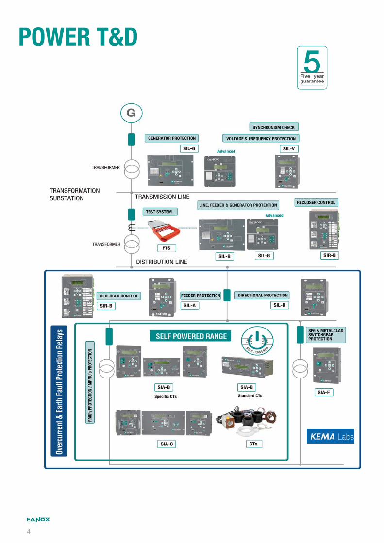
POWER T&D5
Five year guarantee
4

Intelligence applied to Protection Relays
Self powered Technology Solution
We are a reference as specialists in SELF POWERED Protection Relays designing and manufacturing. Successfully proven experience, thousands of field installed devices operating in top conditions for over 15 years.Our innovative spirit, the direct care of the market requirements and our extensive expertise in the manufacture of Protection Relays, have made our Self powered Relays a reference worldwide.Furthermore, our Relays include the latest Technology: LCD, keyboard, event recording, SCADA communication, PC software Utilities worldwide have relied on our technology.
Main advantages over other brands:
The Relays are Self powered by the current measured by the CTs fitted on the lines. The MAIN ADVANTAGE comparing with other self powered relays in the market is that Fanox Relays do not required internal batteries. This means that the maintenance of transformation centers is heavily reduced.
High electromagnetic compatibility makes Fanox Relays the safest in the market. KEMA certification proves it.
5 years warranty.
Standard CTs /1A or /5A can be used saving money when specific CTs are not required.
Fanox Self powered Relays are able to trip all the strikers in the market. Thanks to a setting that allows the user to select the required voltage by the striker.
LOCAL AND REMOTE communication.
Very intuitive menu, extremely easy to set.
Our flexible design offers solutions for all the applications worldwide: coils, strikers, dual-powered installations...
No one in the market gives more quality and specifications with so competitive prices.
Besides, all models can be powered from an external battery, in order to facilitate the commissioning of the centers (the settings and configuration procedure can be carried out without installing the relay), to manage the incidents that may occur and also to manage the devices in adverse conditions.
55

Overcurrent and Earth Fault Protection Relay
Secondary Distribution Protection, RMUs and SF6
insulated Switchgears
Dual & Self powered OC&EF protection relay (with universal auxiliary voltage) using the operating current through /1 standard CTs.
With LOAD DATA PROFILING (current demand).
Stores up to 1024 events and DFR (20 fault reports in data format and 10 reports in COMTRADE format) in non-volatile RAM memory.
Configurable inputs, outputs and leds thanks to Programmable Logic Control (PGC).
Test menu allows the trip circuit to be tested before the transformation center is powered up.
With LEDs maintaining their position even though the relay loses the supply.
Self diagnosis of the status (WATCHDOG) through leds and physical outputs.
Internal Commissioning battery. (Lithium battery: 20 years lifetime).
High electomagnetic compatibility.
Low power consumption.
In Self powered mode, SIA-B starts-up from 75 mA (in secondary) in three phase system/160 mA (in secondary) in single phase system.
Micro USB front port connection (ModBus RTU protocol) for local communication. Remote communication through rear RS485 (ModBus RTU or DNP 3.0 selectable by general setting).
Advanced OC&EF Dual & Self Powered Protection Relay
SIA-BStandard CT’s
ANSI CODE PROTECTIONS
50 Instantaneous phase overcurrent
51 Inverse time phase overcurrent
50GInstantaneous measured neutral overcurrent
51GInverse time measured neutral overcurrent
SHB Second Harmonic Blocking
49T External trip
46 Phase balance current protection
49 Thermal overload
CLP Cold Load Pickup
52 Breaker wear monitoring
50BF Circuit Breaker Failure
68 Zone selection interlocking
TBTrip block for switch disconnector
PGC Programmable logic control
SELF POWERED TECHNOLOGY
6
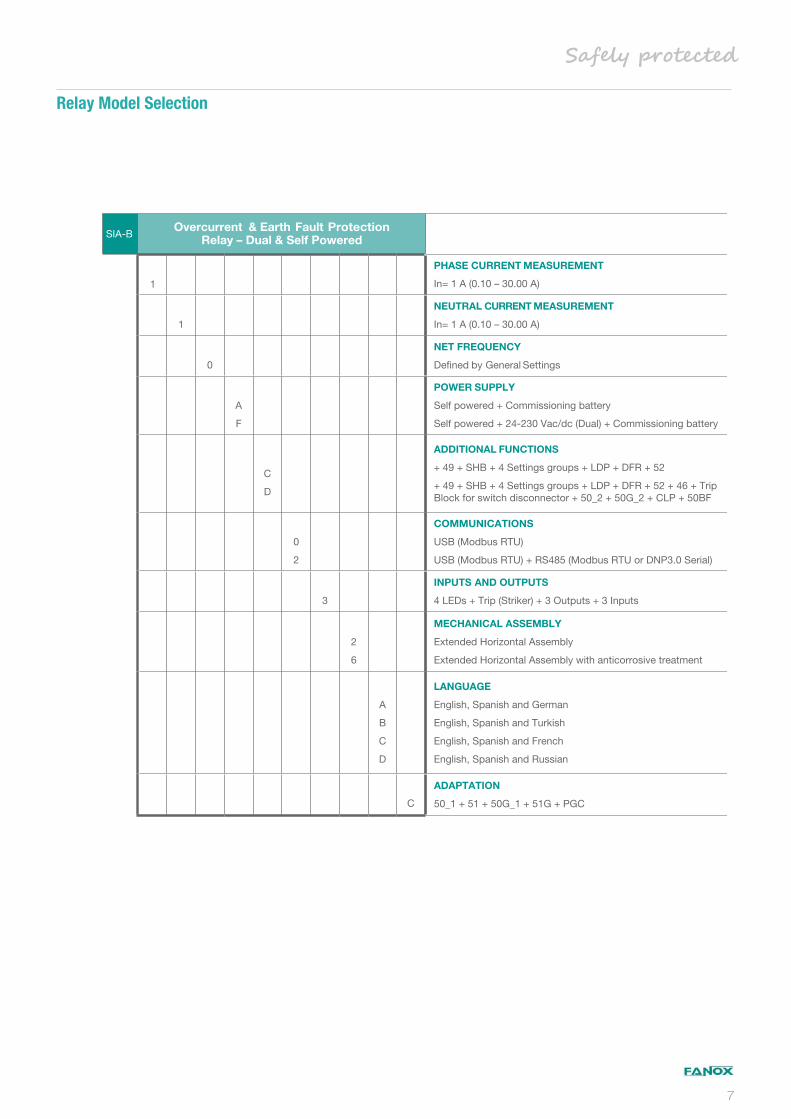
SIA-BOvercurrent & Earth Fault Protection
Relay – Dual & Self Powered
1
PHASE CURRENT MEASUREMENT
In= 1 A (0.10 – 30.00 A)
1
NEUTRAL CURRENT MEASUREMENT
In= 1 A (0.10 – 30.00 A)
0
NET FREQUENCY
Defi ned by General Settings
A
F
POWER SUPPLY
Self powered + Commissioning battery
Self powered + 24-230 Vac/dc (Dual) + Commissioning battery
C
D
ADDITIONAL FUNCTIONS
+ 49 + SHB + 4 Settings groups + LDP + DFR + 52
+ 49 + SHB + 4 Settings groups + LDP + DFR + 52 + 46 + Trip Block for switch disconnector + 50_2 + 50G_2 + CLP + 50BF
0
2
COMMUNICATIONS
USB (Modbus RTU)
USB (Modbus RTU) + RS485 (Modbus RTU or DNP3.0 Serial)
3
INPUTS AND OUTPUTS
4 LEDs + Trip (Striker) + 3 Outputs + 3 Inputs
2
6
MECHANICAL ASSEMBLY
Extended Horizontal Assembly
Extended Horizontal Assembly with anticorrosive treatment
A
B
C
D
LANGUAGE
English, Spanish and German
English, Spanish and Turkish
English, Spanish and French
English, Spanish and Russian
C
ADAPTATION
50_1 + 51 + 50G_1 + 51G + PGC
Relay Model Selection
7
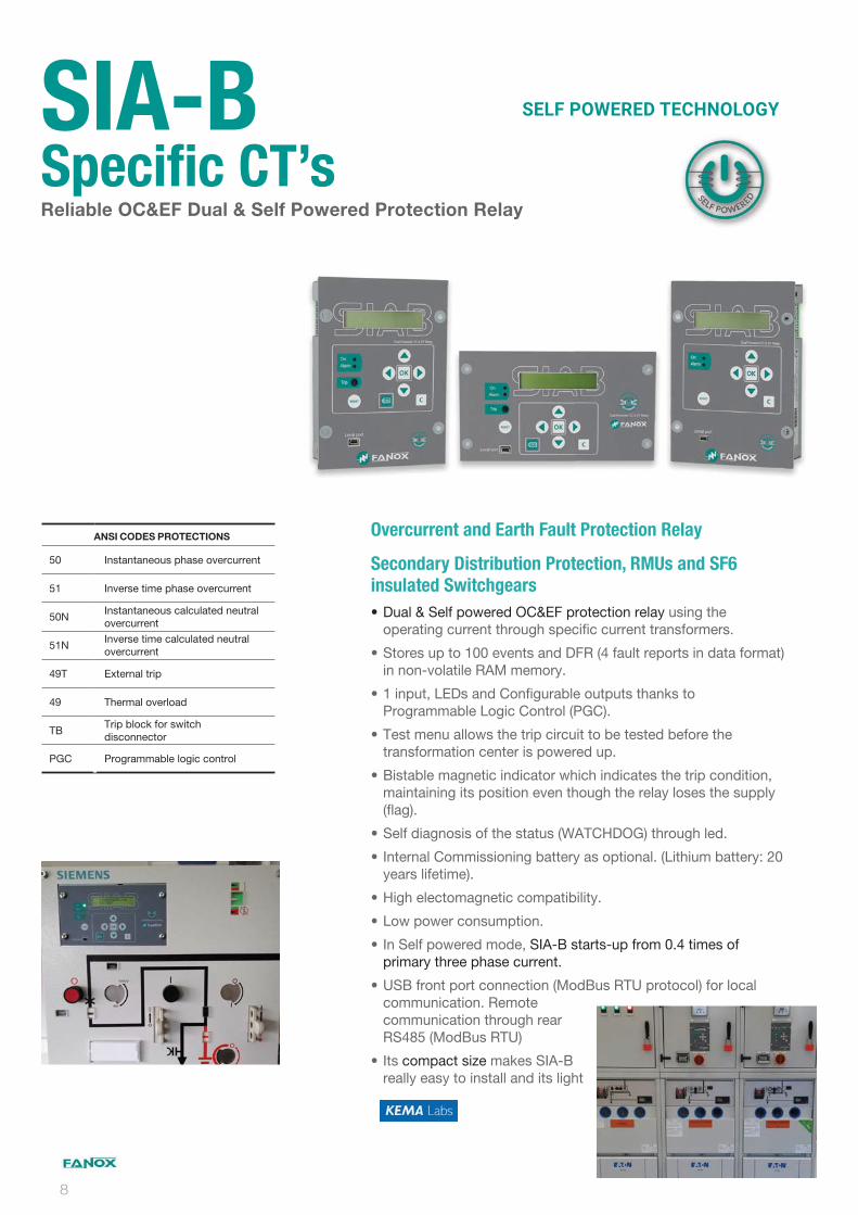
Overcurrent and Earth Fault Protection Relay
Secondary Distribution Protection, RMUs and SF6
insulated Switchgears
Dual & Self powered OC&EF protection relay using the operating current through specific current transformers.
Stores up to 100 events and DFR (4 fault reports in data format) in non-volatile RAM memory.
1 input, LEDs and Configurable outputs thanks to Programmable Logic Control (PGC).
Test menu allows the trip circuit to be tested before the transformation center is powered up.
Bistable magnetic indicator which indicates the trip condition, maintaining its position even though the relay loses the supply (flag).
Self diagnosis of the status (WATCHDOG) through led.
Internal Commissioning battery as optional. (Lithium battery: 20 years lifetime).
High electomagnetic compatibility.
Low power consumption.
In Self powered mode, SIA-B starts-up from 0.4 times of primary three phase current.
USB front port connection (ModBus RTU protocol) for local communication. Remote communication through rear RS485 (ModBus RTU)
Its compact size makes SIA-B really easy to install and its light
Reliable OC&EF Dual & Self Powered Protection Relay
SIA-BSpecific CT’s
ANSI CODES PROTECTIONS
50 Instantaneous phase overcurrent
51 Inverse time phase overcurrent
50NInstantaneous calculated neutral overcurrent
51NInverse time calculated neutral overcurrent
49T External trip
49 Thermal overload
TBTrip block for switch disconnector
PGC Programmable logic control
SELF POWERED TECHNOLOGY
8

SIA-BOvercurrent & Earth Fault Protection
Relay – Dual & Self Powered
0
PHASE CURRENT MEASUREMENT
Defi ned by General Settings
0
NEUTRAL CURRENT MEASUREMENT
Internal measurement
0
NET FREQUENCY
Defi ned by General Settings
0
1
2
3
A
B
C
D
POWER SUPPLY
Self powered
Self powered + 230 Vac (Dual)
Self powered + 110 Vac (Dual)
Self powered + 24 Vdc (Dual)
Self powered + Commissioning battery
Self powered + 230 Vac (Dual) + Commissioning battery
Self powered + 110 Vac (Dual) + Commissioning battery
Self powered + 24 Vdc (Dual) + Commissioning battery
0
1
B
ADDITIONAL FUNCTIONS
-
+ 49
+ Trip Block for switch disconnector
0
1
COMMUNICATIONS
USB (Modbus RTU)
USB (Modbus RTU) + RS485 (Modbus RTU)
0
1
2
INPUTS AND OUTPUTS
Trip (striker)
Trip (striker) + External trip input (49T) + 1 magnetic indicator
Trip (striker) + External trip input (49T) + 1 magnetic indicator + 2 outputs
0
1
4
5
MECHANICAL ASSEMBLY
Vertical Assembly
Horizontal Assembly
Vertical Assembly with anticorrosive treatment
Horizontal Assembly with anticorrosive treatment
A
B
C
D
LANGUAGE
English, Spanish and German
English, Spanish and Turkish
English, Spanish and French
English, Spanish and Russian
A
ADAPTATION
50 + 51 + 50N + 51N
Relay Model Selection
9

Overcurrent and Earth Fault Protection Relay
Secondary Distribution Protection, RMUs and SF6
insulated Switchgears
Dual & Self powered OC&EF protection relay using the operating current through /1 or /5 standard CTs
With LOAD DATA PROFILING (current demand).
Stores 1024 events and DFR (20 fault reports in data format and 10 reports in COMTRADE format) in non-volatile RAM memory.
Configurable inputs, outputs and leds thanks to Programmable Logic Control (PGC).
Test menu allows the trip circuit to be tested before the transformation center is powered up.
Bistable magnetic indicators which indicate the trip condition, maintaining their position even though the relay loses the supply (flags).
Self diagnosis of the status (WATCHDOG) through leds and physical outputs.
Internal Commissioning battery as optional. (Lithium battery: 20 years lifetime).
High electomagnetic compatibility.
Low power consumption.
In Self powered mode, the SIA-C starts-up from 0.1 times the primary three phase current.
Front port connection (ModBus RTU protocol) for local communication. Remote communication through rear RS485 (ModBus RTU or IEC 60870-5-103 selectable by general setting).
Dual & Self Powered OC&EF Protection Relays
SIA-C
ANSI CODE PROTECTIONS
50 Instantaneous phase overcurrent
51 Inverse time phase overcurrent
50GInstantaneous measured neutral overcurrent
51GInverse time measured neutral overcurrent
SHB Second Harmonic Blocking
49T External trip
46 Phase balance current protection
49 Thermal overload
CLP Cold Load Pickup
46BC Broken Conductor Detection
52 Breaker wear monitoring
79 AC Reclosing device
60CTS Phase CT supervision
74TCS Trip voltage supervision
50BF Circuit Breaker Failure
68 Zone selection interlocking
PGC Programmable logic control
SELF POWERED TECHNOLOGY
10

SIA-COvercurrent & Earth Fault Protection
Relay – Dual & Self Powered
1
5
PHASE CURRENT MEASUREMENT
In= 1 A (0.10 – 30.00 A)
In= 5 A (0.50 – 150.00 A)
1
5
A
B
NEUTRAL CURRENT MEASUREMENT
In= 1 A (0.10 – 30.00 A)
In= 5 A (0.50 – 150.00 A)
In= 0,1 A (0.01 – 3.00 A)
In= 0,2 A (0.02 – 6.00 A)
5
6
NET FREQUENCY
50 Hz
60 Hz
0
1
3
4
5
A
B
D
E
F
POWER SUPPLY
Self powered
Self powered + 230 Vac (Dual)
Self powered + 24 Vdc (Dual)
Self powered + 48 Vdc (Dual)
Self powered + 100/230 Vac/dc (Dual)
Self powered + Commissioning battery
Self powered + 230 Vac (Dual) + Commissioning battery
Self powered + 24 Vdc (Dual) + Commissioning battery
Self powered + 48 Vdc (Dual) + Commissioning battery
Self powered + 100/230 Vac/dc (Dual) + Commissioning battery
0
1
2
3
4
ADDITIONAL FUNCTIONS
Striker
Striker and with external trip (49T)
Coil
Coil and with external trip (49T)
Striker and 230 Vac adapted external trip
0
1
2
COMMUNICATIONS
RS232 (Modbus RTU)
RS232 (Modbus RTU) + RS485 (Modbus RTU)
RS232 (Modbus RTU) + RS485 (Modbus RTU or IEC60870-5-103)
0
1
2
3
INPUTS AND OUTPUTS
Trip
Trip + 2 outputs
Trip + 2 outputs + 2 inputs
Trip + 3 outputs
1
2
MEMORY
Non-volatile RAM memory
Non-volatile RAM memory + Fast start-up
A
B
C
D
LANGUAGE
English, Spanish and German
English, Spanish and Turkish
English, Spanish and French
English, Spanish and Russian
B
C
D
E
F
G
H
I
MECHANICS
Horizontal assembly with 1 magnetic Flag
Horizontal assembly with 3 magnetic Flags
Double rear terminals, Vertical assembly with 1 magnetic Flag
Vertical, Compact Size with 3 magnetic Flags
Vertical, Compact Size with 3 Flags, Backligth LCD, Withdrawable
Vertical Assembly, compact size with 1 magnetic indicator, Backligth LCD
Double rear terminals, Vertical assembly with 1 magnetic Flag with anticorrosive treatment
Vertical, Compact Size with 3 magnetic Flags with anticorrosive treatment
-
A
B
C
ADAPTATION
50_1 + 51 + 50G_1 + 51G +74TCS + PGC
+ 50_2 + 50G_2 + 3 Settings group
+ CLP + 4 Settings groups
+ 50_2 + 50G_2 + 46 + 50BF+ 49 + 79 + 52 + 74CT + 46BC + SHB + 3 settings groups
Relay Model Selection
11
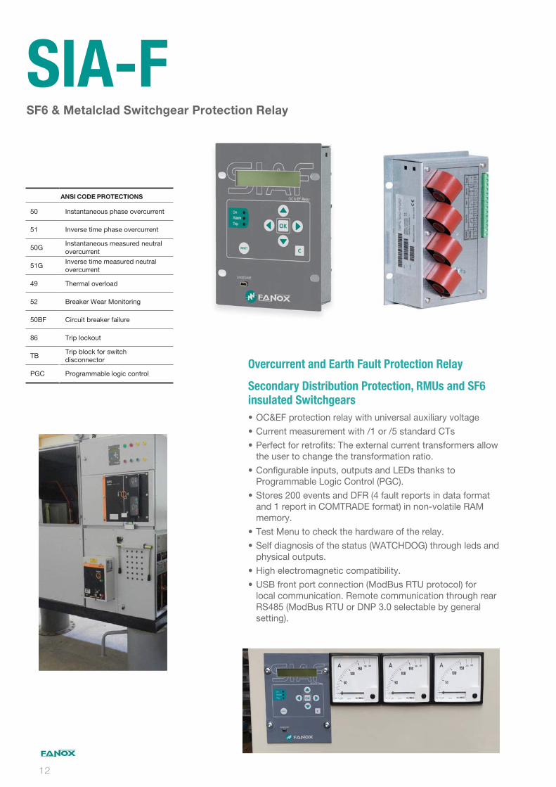
Overcurrent and Earth Fault Protection Relay
Secondary Distribution Protection, RMUs and SF6
insulated Switchgears
OC&EF protection relay with universal auxiliary voltage
Current measurement with /1 or /5 standard CTs
Perfect for retrofits: The external current transformers allow the user to change the transformation ratio.
Configurable inputs, outputs and LEDs thanks to Programmable Logic Control (PGC).
Stores 200 events and DFR (4 fault reports in data format and 1 report in COMTRADE format) in non-volatile RAM memory.
Test Menu to check the hardware of the relay.
Self diagnosis of the status (WATCHDOG) through leds and physical outputs.
High electromagnetic compatibility.
USB front port connection (ModBus RTU protocol) for local communication. Remote communication through rear RS485 (ModBus RTU or DNP 3.0 selectable by general setting).
SF6 & Metalclad Switchgear Protection Relay
SIA-F
ANSI CODE PROTECTIONS
50 Instantaneous phase overcurrent
51 Inverse time phase overcurrent
50GInstantaneous measured neutral overcurrent
51GInverse time measured neutral overcurrent
49 Thermal overload
52 Breaker Wear Monitoring
50BF Circuit breaker failure
86 Trip lockout
TBTrip block for switch disconnector
PGC Programmable logic control
12

SIA-FOvercurrent & Earth Fault
Protection Relay
1
5
PHASE CURRENT MEASUREMENT
In= 1 A (0.10-30.0 A)
In= 5 A (0.50-150.0 A)
1
5
B
NEUTRAL CURRENT MEASUREMENT
In= 1 A (0.10-30.0 A)
In= 5 A (0.50-150.0 A)
In= 0.2 A (0.02-6.0 A)
0
NET FREQUENCY
Defi ned by General Settings
C
POWER SUPPLY
24-220 Vdc / 48-230 Vac
0
1
B
C
ADDITIONAL FUNCTIONS
-
+ 49 + 52 + 50BF
+ Trip block for switch disconnector
+ Trip block for switch disconnector + 49 + 52 + 50BF
0
1
2
COMMUNICATIONS
USB (Modbus RTU)
USB (Modbus RTU) + RS485 (Modbus RTU)
USB (Modbus RTU) + RS485 (DNP3.0 Serial)
0
1
INPUTS AND OUTPUTS
Trip
Trip + 2 Inputs + 2 outputs
0
MECHANICAL ASSEMBLY
Vertical Assembly
A
B
C
D
LANGUAGE
English, Spanish and German
English, Spanish and Turkish
English, Spanish and French
English, Spanish and Russian
A
ADAPTATION
50 + 51 + 50G + 51G + 86 + CLP + PGC
Relay Model Selection
13
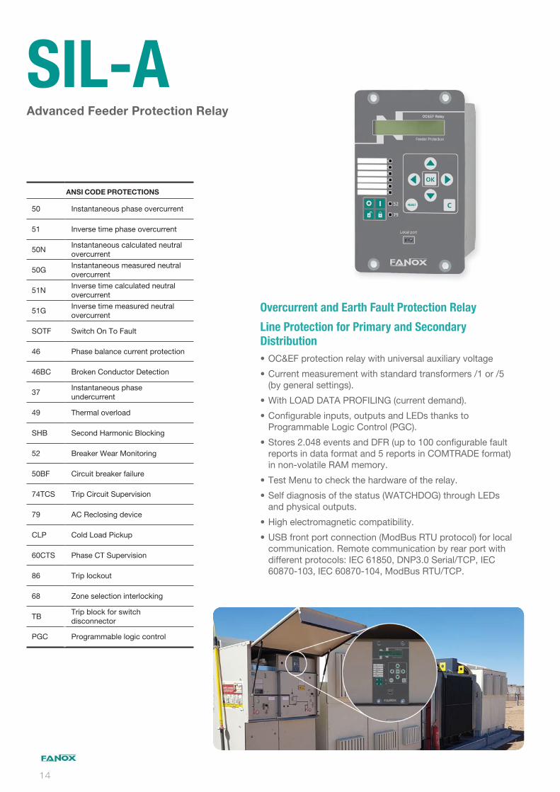
Overcurrent and Earth Fault Protection Relay
Line Protection for Primary and Secondary
Distribution
OC&EF protection relay with universal auxiliary voltage
Current measurement with standard transformers /1 or /5 (by general settings).
With LOAD DATA PROFILING (current demand).
Configurable inputs, outputs and LEDs thanks to Programmable Logic Control (PGC).
Stores 2.048 events and DFR (up to 100 configurable fault reports in data format and 5 reports in COMTRADE format) in non-volatile RAM memory.
Test Menu to check the hardware of the relay.
Self diagnosis of the status (WATCHDOG) through LEDs and physical outputs.
High electromagnetic compatibility.
USB front port connection (ModBus RTU protocol) for local communication. Remote communication by rear port with different protocols: IEC 61850, DNP3.0 Serial/TCP, IEC 60870-103, IEC 60870-104, ModBus RTU/TCP.
Advanced Feeder Protection Relay
SIL-A
ANSI CODE PROTECTIONS
50 Instantaneous phase overcurrent
51 Inverse time phase overcurrent
50NInstantaneous calculated neutral overcurrent
50GInstantaneous measured neutral overcurrent
51NInverse time calculated neutral overcurrent
51GInverse time measured neutral overcurrent
SOTF Switch On To Fault
46 Phase balance current protection
46BC Broken Conductor Detection
37Instantaneous phase undercurrent
49 Thermal overload
SHB Second Harmonic Blocking
52 Breaker Wear Monitoring
50BF Circuit breaker failure
74TCS Trip Circuit Supervision
79 AC Reclosing device
CLP Cold Load Pickup
60CTS Phase CT Supervision
86 Trip lockout
68 Zone selection interlocking
TBTrip block for switch disconnector
PGC Programmable logic control
14
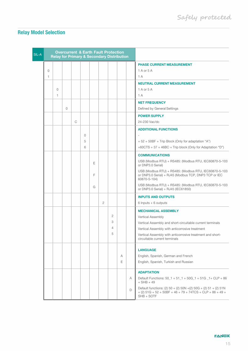
SIL-AOvercurrent & Earth Fault Protection
Relay for Primary & Secondary Distribution
0
1
PHASE CURRENT MEASUREMENT
1 A or 5 A
1 A
0
1
NEUTRAL CURRENT MEASUREMENT
1 A or 5 A
1 A
0
NET FREQUENCY
Defi ned by General Settings
C
POWER SUPPLY
24-230 Vac/dc
0
5
6
ADDITIONAL FUNCTIONS
-
+ 52 + 50BF + Trip Block (Only for adaptation “A”)
+60CTS + 37 + 46BC + Trip block (Only for Adaptation “D”)
E
F
G
COMMUNICATIONS
USB (Modbus RTU) + RS485: (Modbus RTU, IEC60870-5-103 or DNP3.0 Serial)
USB (Modbus RTU) + RS485: (Modbus RTU, IEC60870-5-103 or DNP3.0 Serial) + RJ45 (Modbus TCP, DNP3 TCP or IEC 60870-5-104)
USB (Modbus RTU) + RS485: (Modbus RTU, IEC60870-5-103 or DNP3.0 Serial) + RJ45 (IEC61850)
2
INPUTS AND OUTPUTS
6 Inputs + 6 outputs
2
3
4
5
MECHANICAL ASSEMBLY
Vertical Assembly
Vertical Assembly and short-circuitable current terminals
Vertical Assembly with anticorrosive treatment
Vertical Assembly with anticorrosive treatment and short-circuitable current terminals
A
E
LANGUAGE
English, Spanish, German and French
English, Spanish, Turkish and Russian
A
D
ADAPTATION
Default Functions: 50_1 + 51_1 + 50G_1 + 51G _1+ CLP + 86 + SHB + 49
Default functions: (2) 50 + (2) 50N +(2) 50G + (2) 51 + (2) 51N + (2) 51G + 52 + 50BF + 46 + 79 + 74TCS + CLP + 86 + 49 + SHB + SOTF
Relay Model Selection
15

Overcurrent and Directional Earth Fault Protection
Distribution and Transformation Substations. RMUs
and SF6 insulated Switchgears
OC&EF and Directional Neutral Overcurrent protection relay with universal auxiliary voltage
Current measurement with standard transformers /1 or /5 (by general settings).
With LOAD DATA PROFILING (current demand).
Configurable inputs, outputs and LEDs thanks to Programmable Logic Control (PGC).
Stores 200 events and DFR (20 fault reports in data format and 5 reports in COMTRADE format) in non-volatile RAM memory.
Test Menu to check the hardware of the relay.
Self diagnosis of the status (WATCHDOG) through LEDs and physical outputs.
High electromagnetic compatibility.
Front port connection (ModBus RTU protocol) for local communication. Remote communication by rear port with different protocols: IEC 61850, DNP3.0 TCP, IEC 60870-103, IEC 60870-104, ModBus RTU.
Feeder Protection Relay
SIL-A
ANSI CODE PROTECTIONS
50 Instantaneous phase overcurrent
51 Inverse time phase overcurrent
50GInstantaneous measured neutral overcurrent
51GInverse time measured neutral overcurrent
46 Phase balance current protection
46BC Broken Conductor Detection
37Instantaneous phase undercurrent
60CTS Phase CT supervision
49 Thermal overload
SHB Second Harmonic Blocking
52 Breaker Wear Monitoring
50BF Circuit breaker failure
74TCS Trip Circuit Supervision
79 AC Reclosing device
CLP Cold Load Pickup
49T External Trip
86 Trip lockout
68 Zone selection interlocking
TBTrip block for switch disconnector
PGC Programmable logic control
16
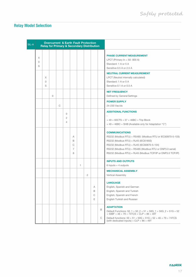
SIL-AOvercurrent & Earth Fault Protection
Relay for Primary & Secondary Distribution
X
0
S
PHASE CURRENT MEASUREMENT
LPCT (Primary In = 50- 800 A)
Standard: 1 A or 5 A
Sensitive 0.5 A or 2.5 A
X
0
S
NEUTRAL CURRENT MEASUREMENT
LPCT (Neutral internally calculated)
Standard: 1 A or 5 A
Sensitive 0.1 A or 0.5 A
0
NET FREQUENCY
Defined by General Settings
C
POWER SUPPLY
24-230 Vac/dc
0
2
4
ADDITIONAL FUNCTIONS
-
+ 49 + 60CTS + 37 + 46BC + Trip Block
+ 49 + 46BC + SHB (Available only for Adaptation “C”)
A
B
C
7
8
COMMUNICATIONS
RS232 (Modbus RTU) + RS485: (Modbus RTU or IEC60870-5-103)
RS232 (Modbus RTU) + RJ45 (IEC61850)
RS232 (Modbus RTU) + RJ45 (IEC60870-5-104)
RS232 (Modbus RTU) + RS485 (Modbus RTU or DNP3.0 serial)
RS232 (Modbus RTU) + RJ45 (Modbus TCP/IP or DNP3.0 TCP/IP)
1
INPUTS AND OUTPUTS
6 Inputs + 4 outputs
2
MECHANICAL ASSEMBLY
Vertical Assembly
A
B
C
E
LANGUAGE
English, Spanish and German
English, Spanish and Turkish
English, Spanish and French
English Turkish and Russian
B
C
ADAPTATION
Default Functions: 50_1 + 50_2 + 51 + 50G_1 + 50G_2 + 51G + 52 + 50BF + 46 + 79 + 74TCS + CLP + 86 + 49T
Default functions: 50 + 51 + 50G + 51G + 52 + 46 + 79 + 74TCS (with dedicated inputs) + CLP + 86 + 49T
Relay Model Selection
17
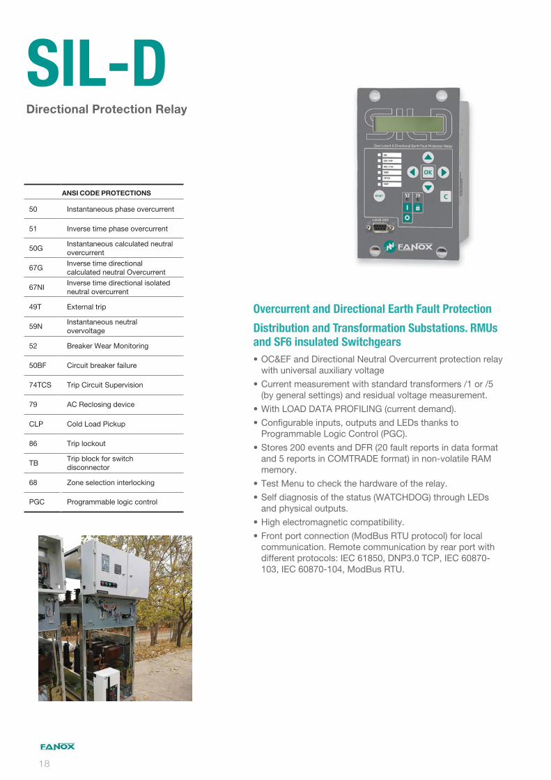
Overcurrent and Directional Earth Fault Protection
Distribution and Transformation Substations. RMUs
and SF6 insulated Switchgears
OC&EF and Directional Neutral Overcurrent protection relay with universal auxiliary voltage
Current measurement with standard transformers /1 or /5 (by general settings) and residual voltage measurement.
With LOAD DATA PROFILING (current demand).
Configurable inputs, outputs and LEDs thanks to Programmable Logic Control (PGC).
Stores 200 events and DFR (20 fault reports in data format and 5 reports in COMTRADE format) in non-volatile RAM memory.
Test Menu to check the hardware of the relay.
Self diagnosis of the status (WATCHDOG) through LEDs and physical outputs.
High electromagnetic compatibility.
Front port connection (ModBus RTU protocol) for local communication. Remote communication by rear port with different protocols: IEC 61850, DNP3.0 TCP, IEC 60870-103, IEC 60870-104, ModBus RTU.
Directional Protection Relay
SIL-D
ANSI CODE PROTECTIONS
50 Instantaneous phase overcurrent
51 Inverse time phase overcurrent
50GInstantaneous calculated neutral overcurrent
67GInverse time directional calculated neutral Overcurrent
67NIInverse time directional isolated neutral overcurrent
49T External trip
59NInstantaneous neutral overvoltage
52 Breaker Wear Monitoring
50BF Circuit breaker failure
74TCS Trip Circuit Supervision
79 AC Reclosing device
CLP Cold Load Pickup
86 Trip lockout
TBTrip block for switch disconnector
68 Zone selection interlocking
PGC Programmable logic control
18

SIL-DOvercurrent & Directional Earth Fault
Protection Relay
X
0
S
NOMINAL PHASE MEASUREMENT
LPCT (Primary = 50 – 800 A)
Standard In= 1 A (0.1-30.0 A) or 5 A (0.5-150 A)
Sensitive In= 0.5 A (0.05-15.0 A) or 2.5 A (0.25-75 A)
X
0
S
NOMINAL NEUTRAL MEASUREMENT
LPCT (Neutral internally calculated)
Standard In= 1 A (0.1-30.0 A) or 5 A (0.5-150 A)
Sensitive In= 0.1 A (0.05-15.0 A) or 0.5 A (0.25-75 A)
0
NET FREQUENCY
(50Hz / 60Hz). Defined by Setting
C
POWER SUPPLY
24-230 Vdc / Vac
0
1
ADDITIONAL FUNCTIONS
-
+ 67NI_1 + 67NI_2
A
B
C
D
REMOTE COMMUNICATIONS
RS232 (Modbus RTU) + RS485 (Modbus RTU or IEC60870-5-103)
RS232 (Modbus RTU) + RJ45 (IEC 61850)
RS232 (Modbus RTU) + RJ45 (DNP3.0 TCP/IP)
RS232 (Modbus RTU) + RJ45 (IEC 60870-5-104)
1
INPUTS AND OUTPUTS
6 Inputs + 4 outputs
2
MECHANICAL ASSEMBLY
Vertical Assembly
A
B
C
E
LANGUAGE
English, Spanish and German
English, Spanish and Turkish
English, Spanish and French
English, Spanish and Russian
A
ADAPTATION
50_1 + 50_2 + 50G_1 + 50G_2 + 51 + 67G_1 + 67G_2 + 52 + 50BF + 79 + 74TCS + CLP + 86 + 49T + 59N + TB
Relay Model Selection
19
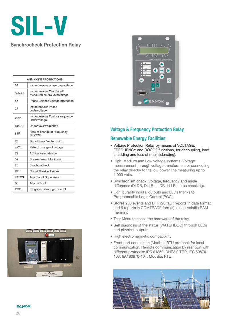
Voltage & Frequency Protection Relay
Renewable Energy Facilities
Voltage Protection Relay by means of VOLTAGE, FREQUENCY and ROCOF functions, for decoupling, load shedding and loss of main (islanding).
High, Medium and Low voltage systems. Voltage measurement through voltage transformers or connecting the relay directly to the low power line measuring up to 1.000 volts.
Synchronism check: Voltage, frequency and angle difference (DLDB, DLLB, LLDB, LLLB status checking).
Configurable inputs, outputs and LEDs thanks to Programmable Logic Control (PGC).
Stores 200 events and DFR (20 fault reports in data format and 5 reports in COMTRADE format) in non-volatile RAM memory.
Test Menu to check the hardware of the relay.
Self diagnosis of the status (WATCHDOG) through LEDs and physical outputs.
High electromagnetic compatibility
Front port connection (Modbus RTU protocol) for local communication. Remote communication by rear port with different protocols: IEC 61850, DNP3.0 TCP, IEC 60870-103, IEC 60870-104, ModBus RTU.
Synchrocheck Protection Relay
SIL-V
ANSI CODE PROTECTIONS 59 Instantaneous phase overvoltage
59N/GInstantaneous Calculated/Measured neutral overvoltage
47 Phase Balance voltage protection
27Instantaneous Phase undervoltage
27V1Instantaneous Positive sequence undervoltage
81O/U Under/Overfrequency
81RRate of change of Frequency (ROCOF)
78 Out of Step (Vector Shift)
V/ t Rate of change of voltage
79 AC Reclosing device
52 Breaker Wear Monitoring
25 Synchro Check
BF Circuit Breaker Failure
74TCS Trip Circuit Supervision
86 Trip Lockout
PGC Programmable logic control
20
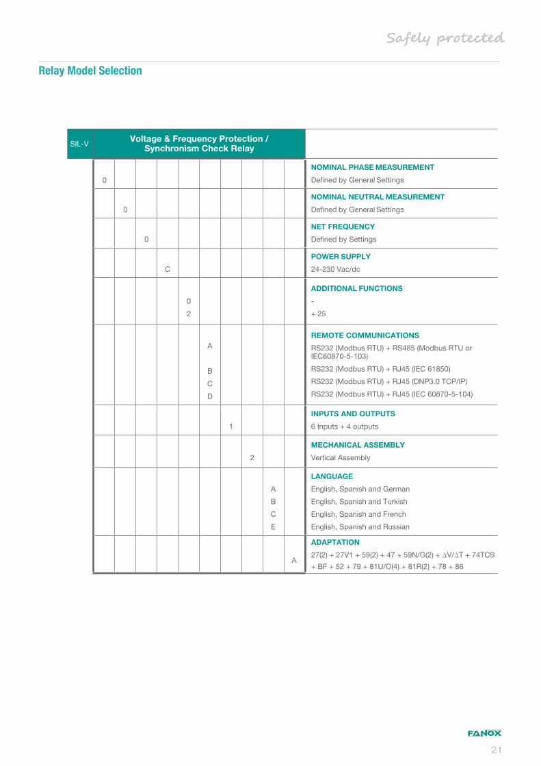
SIL-VVoltage & Frequency Protection /
Synchronism Check Relay
0
NOMINAL PHASE MEASUREMENT
Defined by General Settings
0
NOMINAL NEUTRAL MEASUREMENT
Defined by General Settings
0
NET FREQUENCY
Defined by Settings
C
POWER SUPPLY
24-230 Vac/dc
0
2
ADDITIONAL FUNCTIONS
-
+ 25
A
B
C
D
REMOTE COMMUNICATIONS
RS232 (Modbus RTU) + RS485 (Modbus RTU or IEC60870-5-103)
RS232 (Modbus RTU) + RJ45 (IEC 61850)
RS232 (Modbus RTU) + RJ45 (DNP3.0 TCP/IP)
RS232 (Modbus RTU) + RJ45 (IEC 60870-5-104)
1
INPUTS AND OUTPUTS
6 Inputs + 4 outputs
2
MECHANICAL ASSEMBLY
Vertical Assembly
A
B
C
E
LANGUAGE
English, Spanish and German
English, Spanish and Turkish
English, Spanish and French
English, Spanish and Russian
A
ADAPTATION
27(2) + 27V1 + 59(2) + 47 + 59N/G(2) + V/ T + 74TCS
+ BF + 52 + 79 + 81U/O(4) + 81R(2) + 78 + 86
Relay Model Selection
21

Protection for Renewable Energy Facilities, Industrial
Plants and Secondary Network
Current, Voltage and Fequency Protection
Feeder/Generator protection relay by means of CURRENT, VOLTAGE, FREQUENCY and ROCOF functions.
Two power supply options:
Universal supply
Self-powered through the voltage transformers
Current measurement with standard transformers /1 or /5 (by general settings).
Voltage measurement through voltage transformers or connecting the relay directly to low power line measuring up to 1.000 volts.
With DATA PROFILING (Active, Reactive and Apparent power demand).
Synchronism check: Voltage, frequency and angle difference (DLDB, DLLB, LLDB, LLLB status checking).
Arc Flash detection (AFD) with 4 AFD inputs and 4 high-speed outputs.
Configurable inputs, outputs and LEDs thanks to Programmable Logic Control (PGC).
Stores up to 3.072 events and DFR (up to 100 fault reports in data format and in COMTRADE format) in non-volatile RAM memory.
Test Menu to check the hardware of the relay.
Self diagnosis of the status (WATCHDOG) through LEDs and physical outputs.
High electromagnetic compatibility.
Micro USB front port connection (Modbus RTU protocol) for local communication. Remote communication by rear ports with different protocols: IEC 61850, DNP3.0 Serial/TCP, IEC 60870-5-103, HSR, ModBus RTU/TCP.
Wireless communication via WIFI.
Line, Feeder & Generator Protection Relay
SIL-G
ANSI CODE PROTECTIONS 50 Instantaneous phase overcurrent
67Inverse Time Directional Phase Overcurrent
50NInstantaneous calculated neutral overcurrent
50GInstantaneous measured neutral overcurrent
67NInverse Time Directional Calculated Neutral Overcurrent
67GInverse Time Directional Measured Neutral Overcurrent
SOTF Switch On To Fault
46 Phase balance current protection
46BC Broken Conductor Detection
37 Instantaneous phase undercurrent
49 Thermal overload
SHB Second Harmonic Blocking
59 Instantaneous phase overvoltage
59N/GInstantaneous Calculated/Measured neutral overvoltage
59L Instantaneous Line overvoltage
47 Phase Balance voltage protection
27Instantaneous Phase undervoltage
27L Instantaneous Line undervoltage
27V1Instantaneous Positive sequence undervoltage
32 Directional Overpower
81O/U Under/Overfrequency
81RRate of change of Frequency (ROCOF)
78 Out of Step (Vector Shift)
24 Overfluxing
CLP Cold Load pickup
79 AC Reclosing device
52 Breaker Wear Monitoring
25 Synchro Check
50BF Circuit Breaker Failure
74TCS Trip Circuit Supervision
60CTS Phase CT Supervision
60VTS Phase VT Supervision
AFD Arc Flash detection
86 Trip Lockout
68 Zone selection interlocking
PGC Programmable logic control
22
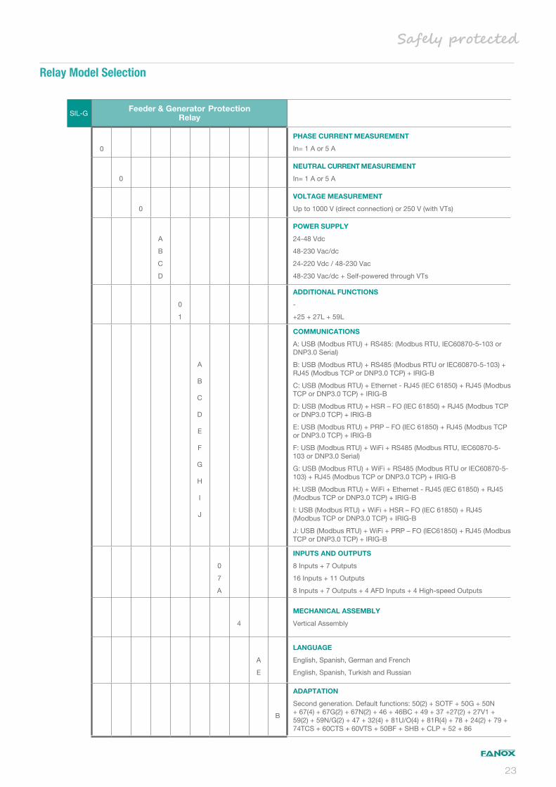
SIL-GFeeder & Generator Protection
Relay
0
PHASE CURRENT MEASUREMENT
In= 1 A or 5 A
0
NEUTRAL CURRENT MEASUREMENT
In= 1 A or 5 A
0
VOLTAGE MEASUREMENT
Up to 1000 V (direct connection) or 250 V (with VTs)
A
B
C
D
POWER SUPPLY
24-48 Vdc
48-230 Vac/dc
24-220 Vdc / 48-230 Vac
48-230 Vac/dc + Self-powered through VTs
0
1
ADDITIONAL FUNCTIONS
-
+25 + 27L + 59L
A
B
C
D
E
F
G
H
I
J
COMMUNICATIONS
A: USB (Modbus RTU) + RS485: (Modbus RTU, IEC60870-5-103 or DNP3.0 Serial)
B: USB (Modbus RTU) + RS485 (Modbus RTU or IEC60870-5-103) + RJ45 (Modbus TCP or DNP3.0 TCP) + IRIG-B
C: USB (Modbus RTU) + Ethernet - RJ45 (IEC 61850) + RJ45 (Modbus TCP or DNP3.0 TCP) + IRIG-B
D: USB (Modbus RTU) + HSR – FO (IEC 61850) + RJ45 (Modbus TCP or DNP3.0 TCP) + IRIG-B
E: USB (Modbus RTU) + PRP – FO (IEC 61850) + RJ45 (Modbus TCP or DNP3.0 TCP) + IRIG-B
F: USB (Modbus RTU) + WiFi + RS485 (Modbus RTU, IEC60870-5-103 or DNP3.0 Serial)
G: USB (Modbus RTU) + WiFi + RS485 (Modbus RTU or IEC60870-5-103) + RJ45 (Modbus TCP or DNP3.0 TCP) + IRIG-B
H: USB (Modbus RTU) + WiFi + Ethernet - RJ45 (IEC 61850) + RJ45 (Modbus TCP or DNP3.0 TCP) + IRIG-B
I: USB (Modbus RTU) + WiFi + HSR – FO (IEC 61850) + RJ45 (Modbus TCP or DNP3.0 TCP) + IRIG-B
J: USB (Modbus RTU) + WiFi + PRP – FO (IEC61850) + RJ45 (Modbus TCP or DNP3.0 TCP) + IRIG-B
0
7
A
INPUTS AND OUTPUTS
8 Inputs + 7 Outputs
16 Inputs + 11 Outputs
8 Inputs + 7 Outputs + 4 AFD Inputs + 4 High-speed Outputs
4
MECHANICAL ASSEMBLY
Vertical Assembly
A
E
LANGUAGE
English, Spanish, German and French
English, Spanish, Turkish and Russian
B
ADAPTATION
Second generation. Default functions: 50(2) + SOTF + 50G + 50N + 67(4) + 67G(2) + 67N(2) + 46 + 46BC + 49 + 37 +27(2) + 27V1 + 59(2) + 59N/G(2) + 47 + 32(4) + 81U/O(4) + 81R(4) + 78 + 24(2) + 79 + 74TCS + 60CTS + 60VTS + 50BF + SHB + CLP + 52 + 86
Relay Model Selection
23
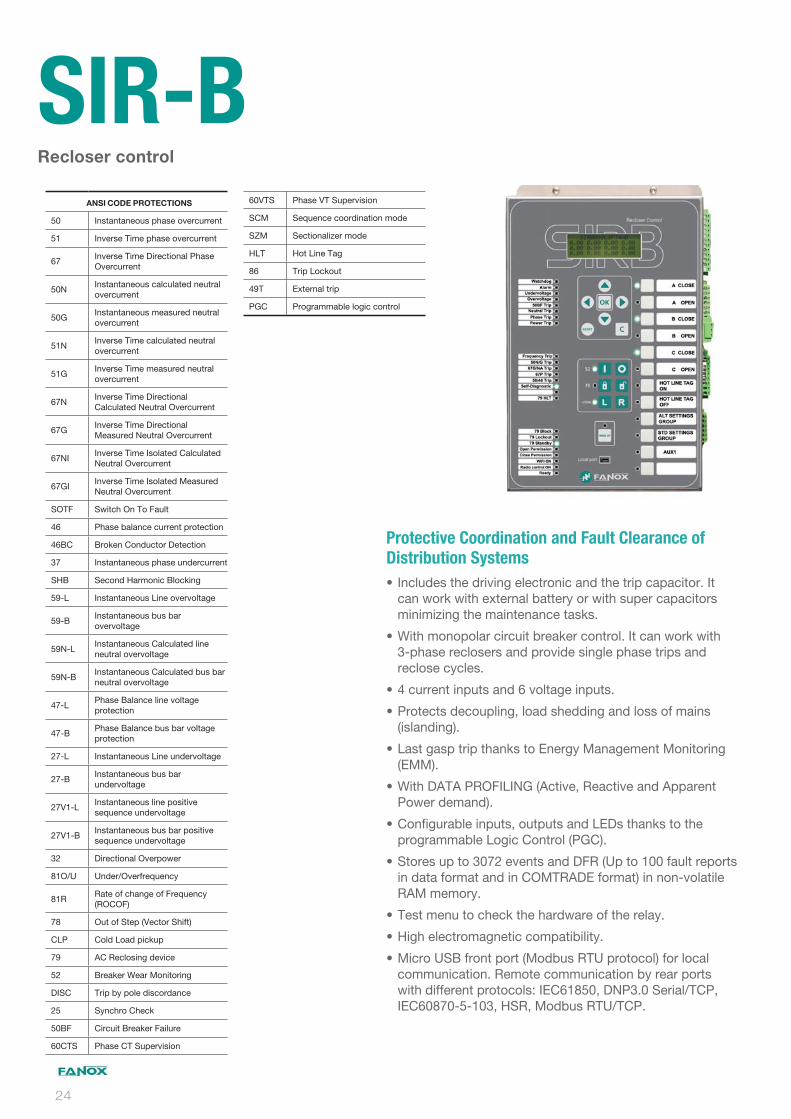
Protective Coordination and Fault Clearance of
Distribution Systems
Includes the driving electronic and the trip capacitor. It can work with external battery or with super capacitors minimizing the maintenance tasks.
With monopolar circuit breaker control. It can work with 3-phase reclosers and provide single phase trips and reclose cycles.
4 current inputs and 6 voltage inputs.
Protects decoupling, load shedding and loss of mains (islanding).
Last gasp trip thanks to Energy Management Monitoring (EMM).
With DATA PROFILING (Active, Reactive and Apparent Power demand).
Configurable inputs, outputs and LEDs thanks to the programmable Logic Control (PGC).
Stores up to 3072 events and DFR (Up to 100 fault reports in data format and in COMTRADE format) in non-volatile RAM memory.
Test menu to check the hardware of the relay.
High electromagnetic compatibility.
Micro USB front port (Modbus RTU protocol) for local communication. Remote communication by rear ports with different protocols: IEC61850, DNP3.0 Serial/TCP, IEC60870-5-103, HSR, Modbus RTU/TCP.
Recloser control
SIR-B ANSI CODE PROTECTIONS
50 Instantaneous phase overcurrent
51 Inverse Time phase overcurrent
67Inverse Time Directional Phase Overcurrent
50NInstantaneous calculated neutral overcurrent
50GInstantaneous measured neutral overcurrent
51NInverse Time calculated neutral overcurrent
51GInverse Time measured neutral overcurrent
67NInverse Time Directional Calculated Neutral Overcurrent
67GInverse Time Directional Measured Neutral Overcurrent
67NIInverse Time Isolated Calculated Neutral Overcurrent
67GIInverse Time Isolated Measured Neutral Overcurrent
SOTF Switch On To Fault
46 Phase balance current protection
46BC Broken Conductor Detection
37 Instantaneous phase undercurrent
SHB Second Harmonic Blocking
59-L Instantaneous Line overvoltage
59-BInstantaneous bus bar overvoltage
59N-LInstantaneous Calculated line neutral overvoltage
59N-BInstantaneous Calculated bus bar neutral overvoltage
47-LPhase Balance line voltage protection
47-BPhase Balance bus bar voltage protection
27-L Instantaneous Line undervoltage
27-BInstantaneous bus bar undervoltage
27V1-LInstantaneous line positive sequence undervoltage
27V1-BInstantaneous bus bar positive sequence undervoltage
32 Directional Overpower
81O/U Under/Overfrequency
81RRate of change of Frequency (ROCOF)
78 Out of Step (Vector Shift)
CLP Cold Load pickup
79 AC Reclosing device
52 Breaker Wear Monitoring
DISC Trip by pole discordance
25 Synchro Check
50BF Circuit Breaker Failure
60CTS Phase CT Supervision
60VTS Phase VT Supervision
SCM Sequence coordination mode
SZM Sectionalizer mode
HLT Hot Line Tag
86 Trip Lockout
49T External trip
PGC Programmable logic control
24

SIR-B Recloser Control
1
PHASE CURRENT MEASUREMENT
In= 1 A
0
NEUTRAL CURRENT MEASUREMENT
In= 1 A
0
1
2
VOLTAGE MEASUREMENT
VT with standard range
Capacitive LEA
Resistive LEA
B
POWER SUPPLY
110-230 Vdc/Vac
0
ADDITIONAL FUNCTIONS
-
A
O
B
P
D
COMMUNICATIONS
A: RS232 (Modbus RTU, IEC60870-5-103 or DNP3.0 Serial)
O: RS485 (Modbus RTU, IEC60870-5-103 or DNP3.0 Serial)
B: RS232 (Modbus RTU, IEC60870-5-103 or DNP3.0 Serial) + RJ45 (Modbus TCP, IEC60870-5-104 or DNP3.0 TCP)
P: RS485 (Modbus RTU, IEC60870-5-103 or DNP3.0 Serial) + RJ45 (Modbus TCP, IEC60870-5-104 or DNP3.0 TCP)
D: RJ45 (IEC 61850) + + RJ45 (Modbus TCP, IEC60870-5-104 or DNP3.0 TCP)
1
2
3
4
5
INPUTS AND OUTPUTS
8 Inputs + 4 Digital Outputs + 3 Analog outputs 30 Vdc
8 Inputs + 4 Digital Outputs + 3 Analog outputs 50 Vdc
8 Inputs + 4 Digital Outputs + 3 Analog outputs 150 Vdc
8 Inputs + 4 Digital Outputs + 3 Analog outputs 220 Vdc
8 Inputs + 4 Digital Outputs + 3 Analog outputs 100 Vdc
0
MECHANICAL ASSEMBLY
Vertical Assembly
A
E
F
LANGUAGE
English, Spanish, German and French
English, Spanish, Turkish and Russian
English, Spanish, Portuguese, Polish
A
ADAPTATION
Default functions: 50(3) + 50N + 50G+ 51(3), 51N + 51G + 67(3) + 67N + 67G+ 67NI + 67GI+ SOTF + 46 + 46BC + 49T + 37 + 27-L + 27-B(2) + 27V1-L + 27V1-B + 47-L + 47-B + 59-L + 59-B(2) + 59N-L + 59N-B + 32(4) + 81O/U(4) + 81R(4) + 78 + CLP + SHB + 50BF + 79 + 52 + pole discordance + 86 +60CTS + 60VTS + SCM + SZM + HLT + 25
Recloser Control Model Selection
25

TRIP CAPACITORS
STRIKERS
TRIP Capacitors –TCM
For SELF POWERED Relays
Connecting trip coil module to the potential-free trip contact of the relay it supplies necessary energy to trip the coil (30J).
Its main functions is to adapt the relay to installations where the line opening system is activated by a coil, instead of a striker.
The TCM (Trip Coil Module) is specifically designed to be used with SELF POWERED relays (SIA-C, SIA-B).
Striker – PRT
This is a single effect solenoid. The striker is spring operated.
The striker is activated by low-power polarised electrical signal supplied by the relay in case of a fault.
The striker is reset to its starting position manually.
CURRENT TRANSFORMERS
Fanox offers complete solutions providing, not only highest quality electronic protection relays, also required current transformers to get protection and measuring capability. Based on relays, different types of current transformers can be used, adapted to customer requirements, both mechanical and functional.
Regarding technical features, all required values that define a CT, as transformation ratio, burden, accuracy class, protection class, frequency, isolation level, ….are adapted to be completely compatible with Fanox electronic Relays.
Furthermore, in case customer has mechanical limitations or a specific CT Type is required, we can study customized production.
Specific CT’s for Self Powered Relays - CT-MTB
Special cores are used to get higher burden and getting anergy in case of sel powered protection relays.
Taped or epoxy resined (Installation around the wire or on the bushings).
Wire or terminals at secondary connection.
Test winding for secondary testing.
5P80 and 10P80 protection class.
Specific dimensions in case installation conditions are really restrictive.
Standard Protection CT’s for Auxiliary Supplied or Self
pecific CT’s for Self Powered Relays - CT-MTS
/1 or /5 secondary protection. Taped or epoxy resined (Installation around the wire or on the bushings).
Wire or terminals at secondary connection. With simple or dual core (Different cores for measurement and power).
Transformation ratio single or multitap.
5P10, 5P20, 10P5 or 10P10 protection class.
From 0.12 VA to 5 VA or higher.
Isolation level 0.72 Kv / 3 Kv.
26

COILS
Coils - BNS
BNS serie electromagnets are simple effect linear solenoids.
The stroke movement from initial to final position is made by electromagnetic forces.
The return to initial position is made by external force or by a spring incorporated to the solenoid.
ACCESORIES
SICOM Communication Software – SICOM
The SICom program works with the Windows® 2000/XP, Windows 7 and Windows 10 operating system and can be used to gain access to all of the relays information, to modify the settings and to save events using a graphic user interface.
Auxiliary Battery Power Supply – KITCOM
The KitCom is an adapter to supply SIA relays through the front communication port, allowing the communication with the computer simultaneously.
This adapter is very useful in the commissioning processes of the transformation centres, allowing full verification of the centre, without any auxiliary power supply.
The equipment has a microswitch that feeds the power supply with a LED (ON) when the voltage is adequate.
In addition to all the necessary to give the power supply, this device has two LED associated with the Rx and Tx lines of communication, and they are used to verify that there is data traffic between the PC and the SIA relay.
TESTING BLOCKS & PLUGS
Test Blocks – FTB/FTP
FANOX FTB/FTP test block allows testing the protection, control, metering and/or communication device of a facility connected to field switchgear, easily and safely, isolating the circuits fully and eliminating all risks for the user.
Maximum safety for the user.
Internal automatic CT short circuiting.
Single hand fully isolated plug.
Locking system for safest operation.
Possibility of horizontal or vertical mounting, respectively.
27

COMMUNICATION SOLUTIONS
5Five year guarantee
28
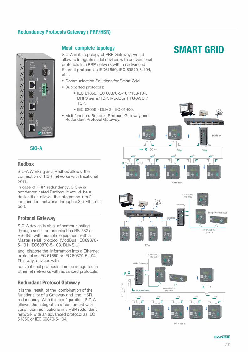
Most complete topology
SIC-A in its topology of PRP Gateway, would allow to integrate serial devices with conventional protocols in a PRP network with an advanced Ehernet protocol as IEC61850, IEC 60870-5-104, etc..
Communication Solutions for Smart Grid.
Supported protocols:
IEC 61850, IEC 60870-5-101/103/104, DNP3 serial/TCP, ModBus RTU/ASCII/TCP.
IEC 62056 - DLMS, IEC 61400.
Multifunction: Redbox, Protocol Gateway and Redundant Protocol Gateway.
RedBox
HSR IEDs
B A
IEC 61850
MODBUS RTU(RS-485)
MODBUS RTU(RS-232)
Gateway
IEDs
Self powered Relays
MODBUS RTU(RS-485)
MODBUS RTU(RS-232)
HSR Gateway
HSR IEDs
IEC 61850 (HSR)
IEC
618
50 (
HS
R)
U
SMART GRID
SIC-A
Redbox
SIC-A Working as a Redbox allows the connection of HSR networks with traditional ones. In case of PRP redundancy, SIC-A is not denominated Redbox, it would be a device that allows the integration into 2 independent networks through a 3rd Ethernet port.
Protocol Gateway
SIC-A device is able of communicating through serial communication RS-232 or RS-485 with multiple equipment with a Master serial protocol (ModBus, IEC69870-5-101, IEC60870-5-103, DLMS…)and dispose the information into a Ethernet protocol as IEC 61850 or IEC 60870-5-104. This way, devices withconventional protocols can be integrated in Ethernet networks with advanced protocols.
Redundant Protocol Gateway
It is the result of the combination of the functionality of a Gateway and the HSR redundancy. With this configuration, SIC-A allows the integration of equipment with serial communications in a HSR redundant network with an advanced protocol as IEC 61850 or IEC 60870-5-104.
Redundancy Protocols Gateway ( PRP/HSR)
29
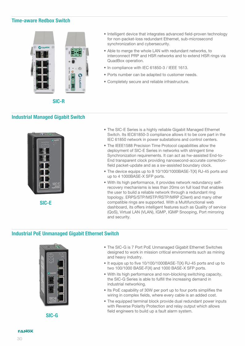
Intelligent device that integrates advanced field-proven technology for non-packet-loss redundant Ethernet, sub-microsecond synchronization and cybersecurity.
Able to merge the whole LAN with redundant networks, to interconnect PRP and HSR networks and to extend HSR rings via QuadBox operation.
In compliance with IEC 61850-3 / IEEE 1613.
Ports number can be adapted to customer needs.
Completely secure and reliable infrastructure.
The SIC-E Series is a highly reliable Gigabit Managed Ethernet Switch. Its IEC61850-3 compliance allows it to be core part in the IEC 61850 network in power substations and control centers.
The IEEE1588 Precision Time Protocol capabilities allow the deployment of SIC-E Series in networks with stringent time Synchronization requirements. It can act as hw-assisted End-to-End transparent clock providing nanosecond-accurate correction-field packet-update and as a sw-assisted boundary clock.
The device equips up to 8 10/100/1000BASE-T(X) RJ-45 ports and up to 4 1000BASE-X SFP ports.
With its high performance, it provides network redundancy self-recovery mechanisms is less than 20ms on full load that enables the user to build a reliable network through a redundant ring topology. ERPS/STP/MSTP/RSTP/MRP (Client) and many other compatible rings are supported. With a Multifunctional web dashboard, its offers intelligent features such as Quality of service (QoS), Virtual LAN (VLAN), IGMP, IGMP Snooping, Port mirroring and security.
The SIC-G is 7 Port PoE Unmanaged Gigabit Ethernet Switches designed to work in mission critical environments such as mining and heavy industry.
It equips up to five 10/100/1000BASE-T(X) RJ-45 ports and up to two 100/1000 BASE-F(X) and 1000 BASE-X SFP ports.
With its high performance and non-blocking switching capacity, the SIC-G Series is able to fulfill the increasing demand in industrial networking.
Its PoE capability of 30W per port up to four ports simplifies the wiring in complex fields, where every cable is an added cost.
The equipped terminal block provide dual redundant power inputs with Reverse Polarity Protection and relay output which allows field engineers to build up a fault alarm system.
SIC-R
SIC-E
SIC-G
Time-aware Redbox Switch
Industrial Managed Gigabit Switch
Industrial PoE Unmanaged Gigabit Ethernet Switch
30
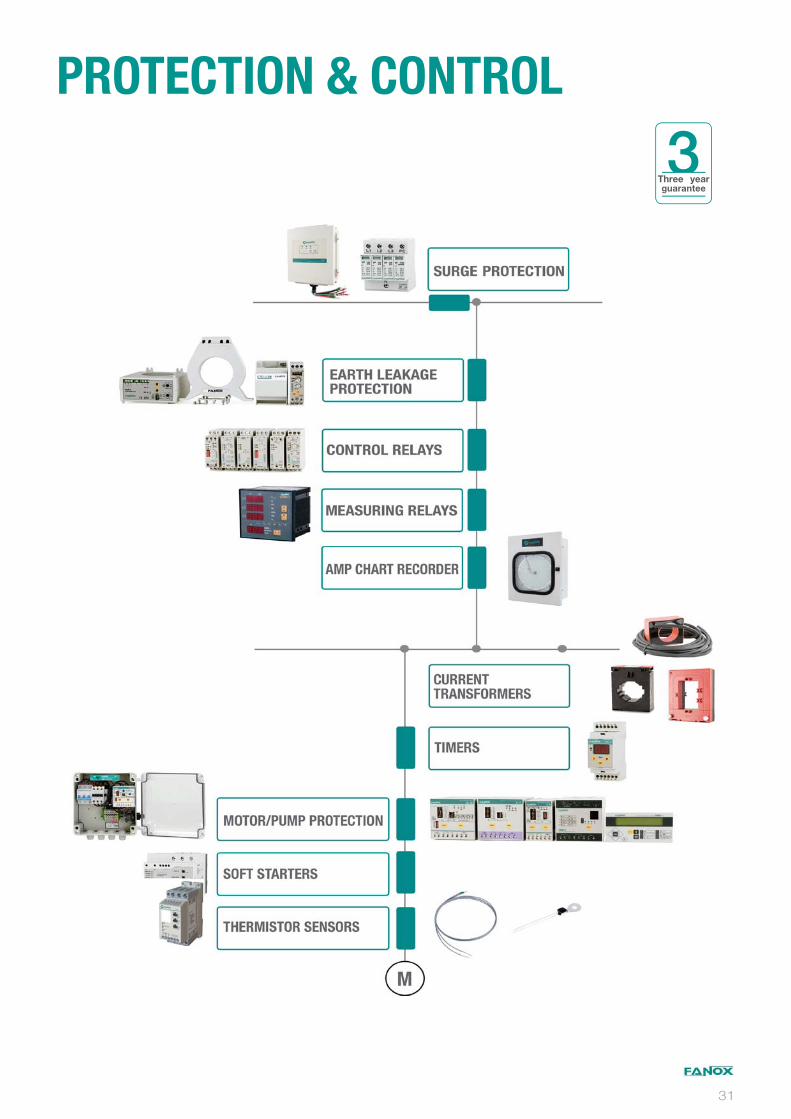
PROTECTION & CONTROL
3Three year guarantee
31
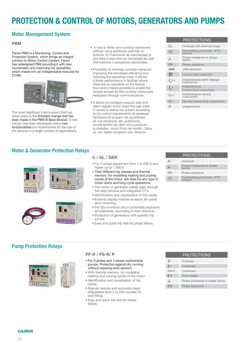
PROTECTION & CONTROL OF MOTORS, GENERATORS AND PUMPS
PBM
Fanox PBM is a Monitoring, Control and Protection System, which brings an integral solution to Motor Control Centers. Fanox has redesigned PBM providing it with new functionality and improving his operability, which makes him an indispensable resource for CCMs.
The most significant improvement that has taken place is the firmware change that has been made in the PBM-B Base Module. A new version has been developed where new functionalities are implemented for the use of the devices in a larger number of applications.
In two or three wire run/stop maneuvers without using additional switches or buttons. En maniobras de marcha/paro a dos hilos o tres hilos sin necesidad de usar interruptores o pulsadores adicionales.
Possibility of remotely run/stop maneuver improving the processes efficiency and reducing the operating costs. It allows a faster performance in facilities where there are no operators on the factory floor and it makes possible to enable the remote access for the run/stop maneuvers realization through communications.
It allows to configure outputs, leds and alarm signals which helps the user when it comes to define the system according to his control requirements.Ali tandesse factoracre di ia quem me auciptintem ex nos obsessus, ete, publicavoc, orunte acerfiri tat, dem uncut pulocum suntebefes, novis. Pulis me menihi, Catus et; non Itaben siceperur utur, tilissum
PROTECTIONSOverload with thermal image
Overheating protection (PTC sensor)Phase imbalance or phase failure
Phase sequence
JAM detection
Locked rotor detection
Instantaneous earth leakage overcurrentInstantaneous inverse time overcurrentInstantaneous neutral overcurrent
Neutral inverse time overcurrent
Undercurrent
PROTECTIONSOverload
Phase imbalance or phase failure
Phase sequence
Overheating protection (PTC sensor)
PROTECTIONSOverload
Underload
Cos Underload
Overvoltage
Phase imbalance or phase failure
Phase sequence
Motor Management System
C / GL / GEN
For 3-phase equipment from 1 to 630 A and higher up to 1.000 V.Their different trip classes and thermal memory, for modelling heating and cooling cycles of the motor, are ideal for any type of motor starts and long cycle operations.The motor or generator cables pass through the relay sensors and integrated CT’s.Identification and visualisation of trip cause.External display module accesory for panel door mounting.For EEx e motors and in potentially explosive atmospheres, according to Atex directive.Protection of generators with specific trip curves.Easy and quick trip test for phase failure.
Motor & Generator Protection Relays
PF-R / PS-R/ P
For 3-phase and 1-phase submersible pumps. Protection against dry running without requiring level sensors.With thermal memory, for modelling heating and cooling cycles of the motor.Identification and visualisation of trip cause.Manual, remote and automatic reset. (Adjustable from 2 to 240 minutes for well filling).Easy and quick trip test for phase failure.
Pump Protection Relays
32

PROTECTION & CONTROL OF MOTOR, GENERATORS AND PUMPS
CONTROL & MEASUREMENTS
PROTECTIONSSoft startSoft stop
Phase imbalance or phase failure
Overheating protection (PTC sensor)
Phase sequence
ES
They reduce the starting current and eliminate the mechanical blows and pulses when electric motors start and stop.They reduce surges.Built in heat dissipater and electro-mechanical bypass relay..For 3-phase motors from 3 to 45 A (1.1 to 22 kW) / 400 V.Substitutes the conventional contactors: One in direct start-up and three in star-delta start-up cycle. Offers greaer life cycle.
Soft Starters & Motor Controllers
S / ST / TST-24 / MT2
22,5 mm sized relays signalling trip cause. Self powered. DIN rail mounting.Phase and/or Temperature. Thermally protected by use of PTC sensors. Temperature control in the electric panels of lifts in accordance with standard EN 81-1 to comply with the European Lift Directive (95/16/CE).
U1 / U3-S / U3-N
Voltage.Control for three-phase and single-phase devices. Adjustable minimuma nd maximum thresholds. Adjustable trip time delay.
Control Relays
MTR-10
Multifunctional digital timer.
Up to 9 different timings from 0.1s to 99h.
With built-in battery which allows timer to be programmed without connecting to auxiliary voltage. Complete battery discharge does not affect operation or adjustment settings.
Programmable parameters: Initial state of output relays, working mode, number of different times per program, time setting range, command contact.
Timers
PROTECTIONS
Overtemperature
Phase imbalance or phase failure
Phase sequence
Termistor short-circuit
Temperature variation
PROTECTIONSOvervoltage
Undervotage
Phase imbalance or phase failure
Phase sequence
N Loss of neutral
Panels for Submersible PumpsPROTECTIONSOverload
Underload
Cos Underload
Overvoltage
Phase imbalance or phase failure
Phase sequence
Short-circuit
Soft startSoft stop
CBT / CBM / CBS
Panels for submersible pumps. Maximum protection without level electrodes or level relay.Electronic relay incorporated.Quick and easy installation, maintenance free.Installation cost are significantly reduced.Adaptable to installations already in service, without removing the pump.
33
PROTECTION AGAINST TRANSIENT OVERVOLTAGES
LOW VOLTAGE TRANSFORMERS
EARTH LEAKAGE PROTECTION
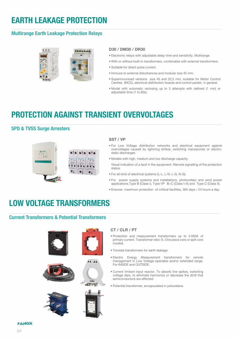
SST / VP
For Low Voltage distribution networks and electrical equipment against overvoltages caused by lightning strikes, switching manoeuvres or electro-static discharges.
Models with high, medium and low discharge capacity.
Visual indication of a fault in the equipment. Remote signalling of the protection status.
For all kind of electrical systems (L-L, L-N, L-G, N-G).
For power supply systems and installations, photovoltaic and wind power applications.Type B (Class I), Type VP B+C (Class I+II) and Type C (Class II).
Ensures maximum protection of criitical facilities, 365 days / 24 hours a day.
SPD & TVSS Surge Arresters
CT / CLR / PT
Protection and measurement transformers up to 5.000A of primary current. Transformer ratio /5. One piece core or split core models.
Toroidal transformers for earth leakage.
Electric Energy Measurement transformers for remote management in Low Voltage openable and/or extended range. For INSIDE and OUTSIDE.
Current limitant input reactor. To absorb line spikes, switching voltage dips, to eliminate harmonics or decrease the di/dt that semiconductors are affected.
Potential transformer, encapsulated in poliuretane.
D30 / DM30 / DR30
Electronic relays with adjustable delay time and sensitivity. Multirange.
With or without built-in transformers, combinable with external transformers.
Suitable for direct pulse current.
Immune to external disturbances and modular size 45 mm.
Superinmunized versions size 45 and 22,5 mm, suitable for Motor Control Centres (MCC), electrical distribution boards and control panels in general.
Model with automatic reclosing up to 3 attempts with defined (1 min) or adjustable time (1 to 60s).
Current Transformers & Potential Transformers
Multirange Earth Leakage Protection Relays
34


02/2020/Rev5
Parque Tecnológico de BizkiaAstondo bidea, Edif. 60448160 DERIO (Spain)tel.: (+34) 94 471 14 09
FANOX reserves the right to modify technical specifications of products contained within this catalogue without previous notice.
More than 100.000 Self powered Relays in the field