Catálogo General UPA 50 Hz 2ª PARTE
20
50 Hz Submersible Borehole Pumps 2 What can you expect from the ”Submersible Borehole Pumps Catalogue”? This catalogue can help you make a -- quick -- first rough selection -- on yourown to find a suitable KSB submersible borehole pump for your application. We have kept the volume of the cata- logue down to what we think is the absolute minimum. For the 4 to 14 inch range, you will find the following in- formation on the pump selected: -- pump series, size and number of stages, -- motor series, size, power, amperage, and allowable temperature, -- starting method, supply voltage and type of installation, -- material variants and -- major dimensions and weights. You may also complete, to the extent possible, the re- quest for quotation on page 9. You will then receive as soon as possible a detailed quotation and, if required, additional literature on KSB submersible borehole pumps from the nearest KSB sales branch. Applications o Drinking and service water supply o Irrigation and spray irrigation o Lowering and maintaining ground water levels o Pressure boosting o Fountains o Mining o Building services systems, for ex. -- Emergency water supply -- Sprinkler systems and more ... Benefits at a Glance + Full range of products + High-tech equipment + Optimum material selection + Maximum efficiency + Functional reliability + Long service life + No maintenance + ”Clean” technology + Customer focus Contents Page The 50 Hz Submersible Borehole Pump Range 3 .... General Description 4 ............................ Submersible Borehole Pump Selection for Deep Wells 7 . Specific Information 8 ............................ Request for Quotation (Form) 9 .................... Head Losses in the Piping 11 ...................... Pump Sets 4 Inches 13 ........................... Pump Sets 6 Inches 21 ........................... Pump Sets 8 Inches/10 Inches 33 .................. Pump Sets 12 Inches/14 Inches 49 ................. Pump Sets 16 Inches and Above 59 ................ Typical Tenders: 4 to 14 Inches 63 ................. Pumps 67 ....................................... Submersible Motors 71 ........................... Accessories 73 .................................. Flow Velocity ”v” Past the Motor 83 ................. Complete Range The complete submersible borehole pump range com- prises pump models for flow rates up to Q = 2 500 m 3 /h (695 l/s) and heads up to H = 1 500 m. The submersible motor range covers sizes for power rat- ings up to P = 3 500 kW and voltages up to U = 10 000 V for 50 and 60 Hz. In addition, a special range is available which includes pumps for higher fluid temperatures and submersible motors with a higher number of poles.
Transcript of Catálogo General UPA 50 Hz 2ª PARTE

50 Hz Submersible Borehole Pumps
2
What can you expect from the ”SubmersibleBorehole Pumps Catalogue”?This catalogue can help you make a-- quick-- first rough selection-- on your ownto find a suitable KSB submersible borehole pump foryour application. We have kept the volume of the cata-logue down to what we think is the absolute minimum.For the 4 to 14 inch range, you will find the following in-formation on the pump selected:-- pump series, size and number of stages,-- motor series, size, power, amperage, and allowabletemperature,
-- startingmethod, supply voltage and type of installation,-- material variants and-- major dimensions and weights.You may also complete, to the extent possible, the re-quest for quotation on page 9.You will then receive as soon as possible a detailedquotation and, if required, additional literature on KSBsubmersible borehole pumps from the nearest KSBsales branch.
Applicationso Drinking and service water supplyo Irrigation and spray irrigationo Lowering and maintaining ground water levelso Pressure boostingo Fountainso Miningo Building services systems, for ex.-- Emergency water supply-- Sprinkler systemsand more ...
Benefits at a Glance+ Full range of products+ High-tech equipment+ Optimum material selection+ Maximum efficiency+ Functional reliability+ Long service life+ No maintenance+ ”Clean” technology+ Customer focus
Contents Page
The 50 Hz Submersible Borehole Pump Range 3. . . .
General Description 4. . . . . . . . . . . . . . . . . . . . . . . . . . . .
Submersible Borehole Pump Selection for Deep Wells 7.
Specific Information 8. . . . . . . . . . . . . . . . . . . . . . . . . . . .
Request for Quotation (Form) 9. . . . . . . . . . . . . . . . . . . .
Head Losses in the Piping 11. . . . . . . . . . . . . . . . . . . . . .
Pump Sets 4 Inches 13. . . . . . . . . . . . . . . . . . . . . . . . . . .
Pump Sets 6 Inches 21. . . . . . . . . . . . . . . . . . . . . . . . . . .
Pump Sets 8 Inches/10 Inches 33. . . . . . . . . . . . . . . . . .
Pump Sets 12 Inches/14 Inches 49. . . . . . . . . . . . . . . . .
Pump Sets 16 Inches and Above 59. . . . . . . . . . . . . . . .
Typical Tenders: 4 to 14 Inches 63. . . . . . . . . . . . . . . . .
Pumps 67. . . . . . . . . . . . . . . . . . . . . . . . . . . . . . . . . . . . . . .
Submersible Motors 71. . . . . . . . . . . . . . . . . . . . . . . . . . .
Accessories 73. . . . . . . . . . . . . . . . . . . . . . . . . . . . . . . . . .
Flow Velocity ”v” Past the Motor 83. . . . . . . . . . . . . . . . .
Complete Range
The complete submersible borehole pump range com-prises pump models for flow rates up to Q = 2 500 m3/h(695 l/s) and heads up to H = 1 500 m.The submersible motor range covers sizes for power rat-ings up to P = 3 500 kW and voltages up to U = 10 000 Vfor 50 and 60 Hz.In addition, a special range is available which includespumps for higher fluid temperatures and submersiblemotors with a higher number of poles.
Submersible Borehole Pumps50 Hz
3
The Submersible Borehole Pump Range 50 Hz
10 20 30 50 10010
20
30
40
50
100
150
200
300
100 200 300
100 200 2000
100
200
300
400
500
600
700800
Hm
Hft
Q m3/h
U.S.gpm
Imp. g. p. m.
5 10 20Q l/s
500
400
1000
2000
1000
1500
2000
5310.7 1000
31 1000.5 5030
2000
500300200
3000
4000
5000
6000
500 100010 50005
10 2000500 1000 5000 100005
200 300 500
1) On request.
(4 inches)Pages 13 to 20
S 100B
UPA150S
UPV150S 1)
UPV200 1)
UPA200
UPA200B
UPA250B
UPA 300UPA 350
UP.. ²²²² 400 1)
BSX - BSF 1)
(6 inches)Pages 21 to 32
(8/10 inches)Pages 33 to 47
(12/14 inches)Pages 49 to 57
(² 16 inches)Pages 59 to 62
60
50 Hz Submersible Borehole Pumps
4
General Description
ApplicationsHandling clean or slightly contaminated water in general watersupply, irrigation and spray irrigation, pressure boosting,emergency water supply, as well as artificial lowering of theground water level and drainage.Also used in mining, sprinkler installations, fountains etc. Per-missible sand content in the fluid pumped: 50 g/m3.
Operating Data 50 HzCapacity Q up to 840 m3/h (233 l/s). . . . . . . . . . . . . . . . . .Head H up to 480 m. . . . . . . . . . . . . . . . . . . . .Temperature of fluid pumped T up to +50 oC.Speed n ¶ 2900 rpm. . . . . . . . . . . . . . . . . . . .Supply voltage U up to 1000 V. . . . . . . . . . . . .
DesignSingle- or multistage centrifugal pumps in pump shroud or inring-section design. Radial or mixed flow hydraulic systems; re-duced impeller diameters also available in some cases. Thestage casings of radial pumps are connected by tie bolts, thoseofmixed flow pumps by stud bolts. Suction casing fitted betweenpumpandmotor. Suction casingequippedwith strainer to protectthe pump from coarse particles in the fluid.Pumps with check valve or connection branch on option. Avail-able with threaded or flanged end on option.Particularly suitable for installation in narrow deep wells.
Type of InstallationIn general, the pumps are installed vertically. Some modelsmay also be installed horizontally depending on the number ofstages and motor size.
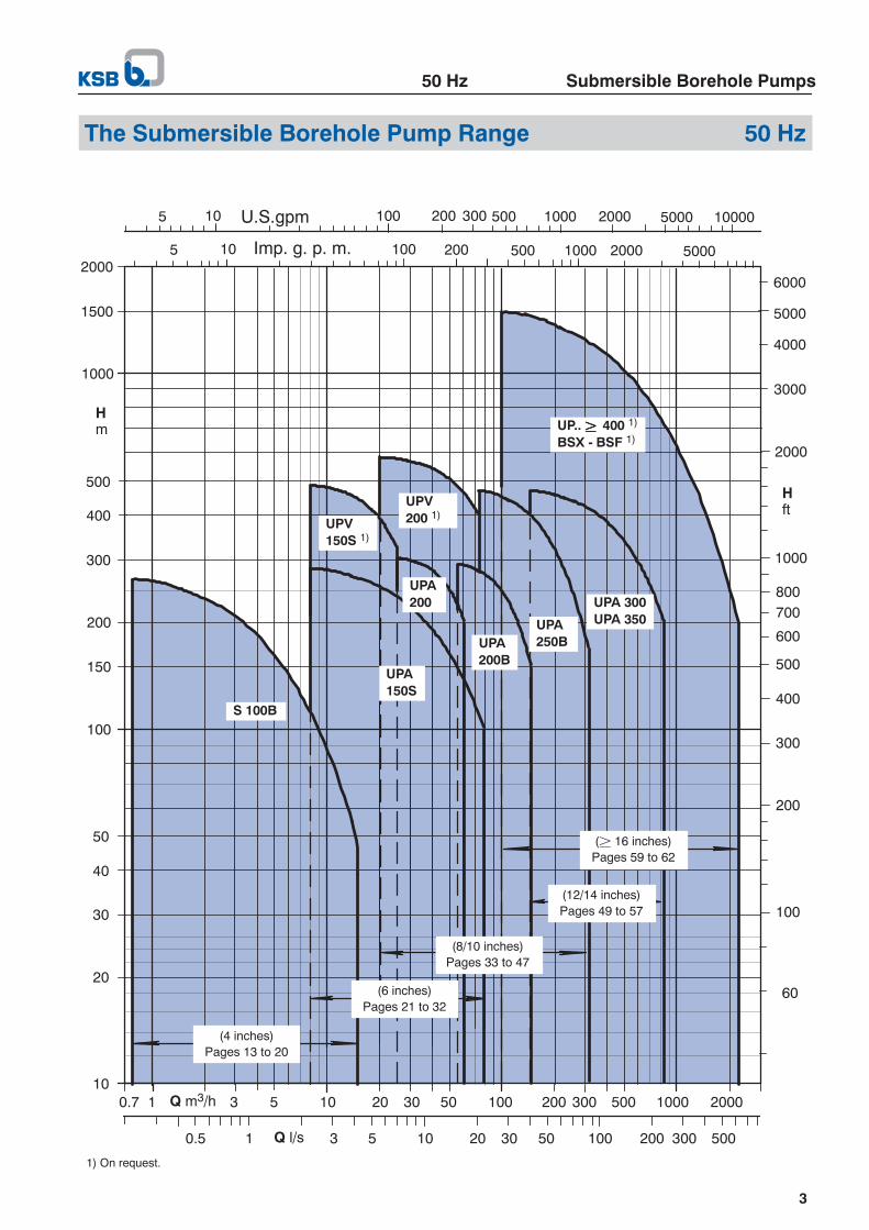
Pump Designation (Example)UPA 200 B -- 80 / 5 b
Type series
Minimum well dia. in mm(for ex.: 200 mm = 8 inches)
Design status
Flow rate Qopt in m3/h (4 10 inches) 1)(50 Hz) l/s (12 inches and above)
Number of stages
Reduced impeller diameters
1) UPA 200 -11 + 14: Q in l/s.
Motor Designation (Example)UMA 250 B 110 / 2 1
Type series
Well dia. (mm)(for ex.: 250 mm = 10 inches)
Design status
Rated power PN for 50 Hz in kW
Number of poles
Winding insulation
MaterialsMaterial variant
Component Standard StandardB
Special
Pump ...
Casing Cast iron or 1)CrNi steel
Bronze or 1)CrNiMo steel
Impeller Glass fibre reinforced NORYL or 1)bronze
Shaft Chrome steel CrNiMo steel
Motor ...
Shaft Chrome steel CrNiMo steel
Housing Cast iron Bronze or 1)CrNiMo steel
Stator case CrNi steel CrNiMo steel
1) For detailed materials data refer to the information given in the”Pumps” and ”Submersible Motors” chapters.
Coating (Standard)Quality 2-component high-build coating (epoxy resin. . . . . . . . .
base), approved for drinking water contact.Coating structure Primer and top coat..Film thickness 100 to 150 µm.. .Colour ultramarine blue (RAL 5002).. . . . . . . . .
DriveSubmersible squirrel-cage motors for single-phase alternatingcurrent (1µ) up to 2.2 kW and for three-phase current (3µ) upto 190 kW, 2900 rpm (2 poles). IP 58 enclosure. For low volt-ages (U± 1000 V). Permissible voltage fluctuation: + 6/-- 10 %of UN (U ± 500 V).Water-filled motor. The water fill lubricates the bearings andcools the windings sealed with water-tight insulation material.The shaft is sealed by lip seals or a mechanical seal. Pressuredifferences between motor and environment are equalized bya rubber expansion diaphragm in the motor. All motors are pro-vided with internal earthing. Motor design is in compliance withVDE regulations.As a rule, pump motors are selected so as to ensure that theycannot be overloaded at any point of the pump characteristiccurve.
StartingD.o.l. (without or with autotransfomer or soft starter) and star-delta starting (UMA motors only).For use with a soft starter also refer to the specific informationon page 8.
Variants Available on Request-- Other materials-- More wear-resistant designs-- Higher fluid temperatures-- 60 Hz motors-- Higher supply voltages-- Models with cooling or pump shroud

Submersible Borehole Pumps50 Hz
5
Connection to Power Supply
The submersible motors are supplied ex factory with 1 or 2standard short motor cables, each equipped with an integratedearth conductor (see details on page 72). Any extension cablesrequired are connected using water-tight cable connectors. Onrequest, the entire length of cable required (± 30m) can be con-nected to the motor at the factory.The standard motor cables and extension cables are suitablefor use at low voltages (U± 1000 V) and approved for drinkingwater contact.Note: The short motor cable is suitable only for use in water. Donot operate the entire motor cable or part of it in air.
Application Temperatures
The submersible borehole pumps are, as a standard, suitablefor use in water with temperatures of up to T = +20 C . An in-dispensable requirement for this is a flow velocity of v²²²²0.2m/spast the motor. This requirement is met, for example, when thepump is installed in adeepwell above thewell screen / filter, etc.With certain restrictions, some motor sizes may also be usedin water with temperatures of up toT = +50 C and for operationwithout an adequate cooling flow of water past the motor, i.e.v = 0 m/s (for example, when the unit is installed in a deep wellbelow the screen / filter area or in a pump sump, etc.).For details refer to the information on temperature limitsgiven for the individual pumpsizes on the followingpages.If the water temperature is higher or if different flow velocities vpast themotor (different installation conditions) are involved, seethe comments on pages 8 and 83 or consult the manufacturer.
Pump Efficiency
The characteristic curves for UPA 200/200B and larger pumpsshow pump efficiency for themaximumand optimum (reduced)impeller diameter (for ex. ”c”). The efficiency of pumps with alow number of stages or considerably reduced impeller diam-eter (for ex. ”d”, “e”) is lower than the value shown; it is givenin the individual characteristic curves specifically prepared forthe quotation.
Variable Speed
The submersible borehole pumps can also be run at variablespeed to accommodate different operating points.For use with a frequency inverter refer to the specific informa-tion on page 8.
Dry Running Protection
For use in wells with marked water level fluctuations or tempor-ary low yield we strongly recommend installing dry runningprotection equipment (”Accessories”).
Typical Installation PositionsVertical installation (for ex. in deep wells)
1 Submersible borehole pump2 Riser3 Cable tie4 Supporting clamp5 Pressure gauge6 Shut--off valve7 Power supply cable8 Control box9 Well screen / filter
D = Inside well diameterTB = Well depthTF = Well screen / filter depthHe = Installation depthHh = Static water levelHt = Dynamic water level
3410:70/4
TB
TF
He
Ht
Hh
1
3
46
5
7
8
9
D
2
Installation instructions:-- Minimum submergence below the lowest water level Ht (dy-
namic water level) relative to the pump’s upper end: 0.5 mor more, i.e. ...-- He -- Ht ² 0.5 m.
-- If a minimum submergence of 0.5 m cannot be ensured, werecommend installing the unit in a pump shroud.
-- Maximum submergence below the highest water level Hh(static water level), i.e. ...-- He -- Hh ± 350 m for DN 100 and DN 150 motors-- He -- Hh ± 500 m for UMA motors
-- It must be ensured that the pump is freely suspended fromthe riser pipe and neither sits on the base of the well nortouches the well casing.
Horizontal installation (for ex. in a tank or pump sump)
3410:71/2
1 Submersible borehole pump 5 Check valvewith adapter 6 Dismantling joint
2 Water storage tank 7 Shut-off valve3 Bearing pedestal 8 Intake4 Expansion joint
Note: For horizontal installation, UMA 200B/250B motors aregenerally equipped with two water storage tanks each.

50 Hz Submersible Borehole Pumps
6
Design Features UPA 200B (8 Inches) and Above
Check valve with anti-blockagevalve disc-- No jamming or tilting.-- Spring-loaded design makes for mini-mum valve closing times and preventswaterhammer.
-- High operating reliability.
Enclosed pump bearing
-- No-maintenance design, high wearresistance.
-- For trouble-free long-term oper-ation.
New: Energy-efficient hydraulicsystems-- High efficiency andlow energy costs.
The KSB motor-- VDE-compliant, i.e., high level ofelectrical safety.
-- Designed for max. pump power toprotect unit from overloads.
Reliable pressure balancingsystem-- Optimum rubber expansiondiaphragm design.
-- Enables installation at very lowdepths.
Robust wear rings-- Replaceable wear rings made ofcorrosion- and wear-resistant metal.
-- Protection against wear in the clear-ance; easy servicing.
Tried and tested thrust bearing-- Water-lubricated self-aligning tilting-pad journal bearing.
-- No-maintenance design suitable formaximum load-carrying capacity undercontinuous operation conditions.
-- New materials combination (stainlesssteel/carbon) for high safety factor.
Counter thrust bearing-- Reliable balancing of negativeaxial thrust.
-- Impellers do not rub on the stagecasings.
Dynamically balanced rotor-- Ensures smooth running.
All wetted plastic components aresuitable for use with drinking water(BAM 1))-- Coating, electric cables, sealelements, gaskets, etc. areabsolutely fit for use in drinking waterapplications.
1) German Federal Institute for MaterialsResearch
3415:24
Integrated sand separator-- Tried and tested KSB patent.-- Added protection from abrasive wear forshafts and bearing areas.
-- Long service life andhigh operating reliability.
Wear-resistant mechanical seal-- Long service life andhigh operating reliability.
For ex.: UPA 200B - 130/2 + UMA 200B .. /21

Submersible Borehole Pumps50 Hz
7
Submersible Borehole Pump Selection for Deep Wells
Pump Selection
The following data are required for a first rough selection ofa submersible borehole pump:
-- Flow rate Q in m3/h (l/s)-- Pressure at well head HA in m-- Well diameter in inches or mm
-- Temperature of fluid pumped TA in C-- Pump head HP in mWhile Q, HA, D and TA are usually specified by the customer,the head HP to be developed by the pump needs to be calcu-lated. There are two typical applications to be considered (seethe drawing on the right):
1.Pumping into an open overhead tank
HP = HA + Ht + Hv + HS [m]
where ...
HA = Required pressure at well head
Ht = Lowest water level (dynamic water level).
Hv = Head losses in the check valve (see characteristiccurves for different stage numbers for UPA 150Sand above).
HS = Head losses in riser pipe up to well head(see page 11).
He = Installation depth
2.Pumping into a closed tank
Hp = HA + Ht + Hv + HS + pü [m]
where ...
pü = Gauge pressure (also air cushion) in a tank.
Example
Given ...
QA = 120 m3/h, HA = 95 m, TA = + 15 C,50 Hz, 400 V and d.o.l. starting,well diameter D = 250 mm (10 inches).
Found ...
1. step: pump type UPA 200B/250B(for QA taken from selection chart on page 3)
2. step: pump size UPA 200B-130(for QA taken from selection chart on page 33)
3. step: pump set UPA 200B-130/6b + UMA 200B 45/21(for Hp = HA + Ht + HV + HS = 95 + 4 + 0.75 + 0.26 = 100 mwith HV taken from characteristic curves for different stagenumbers on page 41).Pump efficiency: ηP = 80.5 % (without check valve)
3300:54/3
Figure:Deep well with submersible borehole pump and overhead tankor closed tank at a pressure above atmospheric pressure of pü.
°
°

50 Hz Submersible Borehole Pumps
8
Specific Information
Application TemperaturesThe details below provide data of adequate accuracy for theallowable temperature as a function of the type of installation,motor size and flow velocity v past the motor:
a) Vertical installation
-- DN 100/DN 150: Tallow = Tmax1) independently of flowpast the motor.
-- UMA 150D/200B: v = 0 m/s Tallow ¶ Tmax1) -- 5 oC,. . .v ² 0.2 m/s Tallow = Tmax1),. .v ² 0.5 m/s Tallow ¶ Tmax1) + 5 oC.. .
-- UMA 250B: v = 0 m/s Please consult. . .manufacturer.
v ² 0.2 m/s Tallow = Tmax1),. .v ² 0.5 m/s Tallow¶ Tmax1), + 5 oC.. .
1) Values taken from the tables on pages 14, 15 etc., 22, 24 etc.
b) Horizontal installationThe principle is the same as for vertical installation.
Exception: Pumps with UMA 250B ... motorsThese units must always be equipped with a flow inducersleeve. The flow inducer sleeve is not required, if the givenpumpis equipped with a motor having a 10 % higher power rating.
For all pump sets:For a flow velocity of v ² 0.5 m/s and horizontal installation,check back with the manufacturer.
Starting with Soft StarterUPA submersible borehole pumps can also be started using asoft starter. Because of their slim design, submersible motorshave considerably smaller moments of inertia for rotors thanconventional dry-installed standardized motors. Therefore, thefollowing rules should be kept in mind:-- Start-up voltage: UA ² 40 % of the rated voltage.-- Acceleration / start ramp: set to tA ± 4 s
(it will then take the motor 2 -- 3 seconds to reach the ratedspeed).
-- Current limiter: set to IA/IN ¶ 3.5.This setting should only be changed if tH± 4 s can be main-tained.
-- Deceleration / stop ramp: set to tD± 4 s. If possible, do notuse a stop ramp at all.
Additional special functions, such as kick-start or boost func-tions, speed control, cos φ optimization, delayed starting, etc.must not be used. Should one of these functions be required,please contact the manufacturer.Note:After the unit has run up to full speed, the soft startermustbe bypassed by a contactor so as to avoid power losses in thesoft starter and the motor. If you have any questions or queriesin this respect, please contact the manufacturer of the softstarter.
Operation with Frequency InverterUPA submersible borehole pumps can also be run on a fre-quency inverter for variable speed operation. Since the electri-cal losses in the motor are higher if a freqency inverter is used,the pump motor should have a 10 % power reserve.Considering the differences between conventional dry-in-stalled standardized motors and submersible motors – thelatter have considerably smaller moments of inertia for rotorsbecause of their slim design, they are equipped with water-lu-bricated plain bearings, etc. – the following rules should be keptin mind:
-- Minimum frequency: fmin = 20 Hz for 2-pole motorsfmin = 30 Hz for 4-pole motors
Independently of the actual supply frequency, a minimumflow of 10% of the pump’s flow rate at best efficiency pointmust always be ensured.
-- Maximum frequency: fmax = 50 or 60 Hz!The rated motor power must not be exceeded.
-- Acceleration ramp time (f = 0 to fmin): tA = 2s.-- Deceleration ramp time (f = 0 to fmin): tD = 2s.-- The rated motor current must not be exceeded.-- Maximum permissible voltage rise≤ 500 V/�s.
Maximum permissible peak voltage to earth for J1 insulation≤ 600 V and for J2 insulation≤ 800 V.Note: Compliance with these limits can usually be assuredby means of a sine filter or du/dt-filter.
-- The control process of the frequency inverter must corre-spond to linear U/f-curve control. If other control principlesare employed, the manufacturer of the frequency invertermust ensure that the special requirements of submersiblemotors are taken into account.
If your application falls under the exceptions mentioned aboveor requires other models (larger sizes, horizontal installation oroperation at frequencies below fmin etc.), please consult thepump manufacturer or the frequency inverter supplier.

F
3300:54/3
3
2
1
4
7
5
8
6
1 Well screen / filter2 Well casing3 Submersible borehole pump4 Riser5 Well head housing6 Well head7 Power supply cable8 Overhead tank
50 Hz Submersible Borehole Pumps
9
Request for Quotation (Form 3400.09 G3)
Weshould like to test the efficiency and quality of your computer-aided quotation process.Please let us have a quotation based on the following data.(Fill in the required data and / or underline the relevant information, as far as available.)
1. Water quality
Temperature oC. . . . . . . . . . . . . . . . . . .
Sand content g/m3. . . . . . . . . . . . . . . . .
Please attach water analysis, if available.
2. Type of system
Well / Mine shaft / Tank
Free discharge above ground
Discharge into an overhead tank
Discharge into a pressure vessel
3. Deep well
Well depth (distance from ground level towell base):
TB = m. . . . . . . . . . . . . . . . . . . . . . . . . . . .
Inside diameter at submersible pumpinstallation depth:
D = mm ( inches). . . . . . . . . . . . . . . . .
Well screen / filter:
-- Installation depth TF = m. . . . . . . . . .
-- Length LF = m. . . . . . . . . . . . . . . . . . .
4. Flow rate
Q = m3/h (l/s). . . . . . . . . . . . . . . . . . . .
5. Total head(including all friction losses)
H = m. . . . . . . . . . . . . . . . . . . . . . . . . . . .
If H is not known, please provide the fol-lowing data:
a)Water level in well, measured
from ground level:
-- Static water level: Hh = m. . . . . . . .
-- Dynamic water level: Ht = m. . . . .
(at flow rate Q = m3/h). . . . . . . . . . .
b)Head above ground:
Geodetic altitude up to the highest
point of the pipeline or up to the
highest water level in the overheadtank:
Hd = m. . . . . . . . . . . . . . . . . . . . . . . . . .
Discharge head required at the endof the piping:
H = m ( bar). . . . . . . . . . . . . . . . . . .
Cut-out pressure in the pressurevessel:
pÜ = bar. . . . . . . . . . . . . . . . . . . . . . . . .
c)Piping outside well head housing:
Overall length m. . . . . . . . . . . . . . . . .
Nominal diameter mm. . . . . . . . . . . .
Number of bends, valves and fittings:
pcs.. . . . . . . . . . . . . . . . . . . . . . . . . . . .
Inside diameter reduced by incrusta-tion to:
D = mm. . . . . . . . . . . . . . . . . . . . . . . .
6. Installation depth
Ground level to check valve / to connec-tion branch:
He = m. . . . . . . . . . . . . . . . . . . . . . . . . . .
Caution: Do not install the submersibleborehole pump at the level of the wellscreen / filter!
7. Power supply
Single- / three-phase alternating current.
Mains voltage at well:
U = V. . . . . . . . . . . . . . . . . . . . . . . . . . . .
Frequency f = Hz. . . . . . . . . . . . . . . . . .
If voltage drops cannot be precluded:
Minimum voltage ...
Umin = V. . . . . . . . . . . . . . . . . . . . . . . . . .
8. Control box
Manual start-up / remote control / auto-matic start-up by way of float switch,pressure switch or dry running protectionequipment.
Other types of switchgear: . . . . . . . . . .
. . . . . . . . . . . . . . . . . . . . . . . . . . . . . . . . . . .
9. Starting method
D.o.l. (without / with autotransformer orsoft starter) or star-delta starting.

50 Hz Submersible Borehole Pumps
10

Submersible Borehole Pumps50 Hz
11
Head Losses in the Piping
3300:103/3-2
HVm/100 m
HVft/100 ft
The friction losses given in the abovechart roughly apply to newcast iron pipes. For new rolled steel or plastic pipes,multiply thevalues by approx. 0.8. For old, slightly rusty cast iron pipes,multiply by approx. 1.25. In pipes with incrustations, frictionlosses may rise to 1.7 times the value given in the chart for the
diameter reduced by incrustations. For pipes subject to con-siderable incrustation, the friction losses can only be deter-mined experimentally.Example: Q = 140 m3/h, new DN 150 cast iron pipe.
HV = 3.25 m per 100 m of pipe, v = 2.2 m/sec.

50 Hz Submersible Borehole Pumps
12

50 Hz S 100B
13
Submersible Borehole Pumps for S 100BWell Diameters of 100 mm (4 Inches) and Above
Selection Chart 50 Hz (Ranges on Offer) n ¶ 2900 rpm
Note: Up to a motor rating of PN = 2.2 kW all pump sizes can be supplied with single-phase a.c. (1 µ) or three-phase current(3 µ) motors.

Capacity in m3/h
H[m]
For information on coolingshroud refer to page 19.
96 mm
104
90A 85
25 25
50 Hz S 100B
14
S 100B - 1 ...for well diameters of 100 mm (4 inches) and above
Pumps with submersible motors for ...-- Fluid temperature up + 30 oC. . . . . . . . . . . . . . . . . . . . . . . .-- Type of current / voltage 1µ/230 V. . . . . . . . . . . . . . . . . . .
or 3µ/400 V. . . . . . . . . . . . . . . . . . . . . . . . . . . . . . . . . . . . . .-- Starting d.o.l.. . . . . . . . . . . . . . . . . . . . . . . . . . . . . . . . . . . . . . .
Rated current forOper-ation
S 100B
Ratedpower(motor)PNkW
1 µ230 V
IN 1)
A
3 µ400 V
INA
Typeof in-stalla-tion2)
withauto-maticcontrolunit 3)
1 / 7 0.37 3.4 1.3 v + h x
1 / 9 0.37 3.4 1.3 v + h x
1 / 12 0.37 3.4 1.3 v + h x
1 / 14 0.55 4.3 1.7 v + h x
1 / 16 0.55 4.3 1.7 v + h
1 / 20 0.55 4.3 1.7 v + h
1 / 25 0.75 5.7 2.2 v x 3)
1 / 30 0.75 5.7 2.2 v x 3)
1 / 35 1.10 8.6 3.2 v x 3)
1 / 40 1.10 8.6 3.2 v x 3)
1 / 50 1.50 10.6 4.0 v x 3)
1) Capacitor run motors (PSC motors) with starter.2) v = vertical and h = angled / horizontal.3) Always check and make sure that the operating pressure of Controlmatic /
Cervomatic units is not exceeded.
Dimensions / Weights / Ident. Numbers / Horizontal Installation1µ / 230 V 3µ / 400 V
S 100BLA
¶ mmmA¶ kg
Ident. No. A¶ mm
LA¶ mm
mA¶ kg
Ident. No. A¶ mm
C
1 / 71 / 91 / 121 / 141 / 161 / 201 / 251 / 301 / 351 / 401 / 50
57562572076581090010401150137014801730
11.511.713.413.613.814.316.316.820.020.622.7
39 019 18439 019 18539 019 18639 019 18739 019 18839 019 18939 019 19039 019 19139 019 19239 019 19339 019 194
371425508552597687---------- -- -- ------------ -- -- ----------
55560570073578087010151125131014201675
10.710.912.212.412.613.114.915.417.418.020.3
39 019 22639 019 22739 019 22839 019 22939 019 23039 019 23139 019 23239 019 23339 019 23439 019 23539 019 236
362416492537582672---------- -- -- ------------ -- -- ----------
G 1” 1/4
Accessories: UPA Control for dry running protection by means of 3 immersionelectrodes; see page 20.
x 3)
x 3)

Capacity in m3/h
H[m]
For information on coolingshroud refer to page 19.
96 mm
104
90A 85
25 25
50 Hz S 100B
15
S 100B - 2 ...for well diameters of 100 mm (4 inches) and above
Pumps with submersible motors for ...-- Fluid temperature up + 30 oC. . . . . . . . . . . . . . . . . . . . . . . .-- Type of current / voltage 1µ/230 V. . . . . . . . . . . . . . . . . . .
or 3µ/400 V. . . . . . . . . . . . . . . . . . . . . . . . . . . . . . . . . . . . . .-- Starting d.o.l.. . . . . . . . . . . . . . . . . . . . . . . . . . . . . . . . . . . . . . .
Rated current for Oper-ation
S 100B
Ratedpower(motor)PNkW
1 µ230 V
IN 1)
A
3 µ400 V
INA
Typeof in-stalla-tion 2)
ationwithauto-maticcontrolunit 3)
2 / 7 0.37 3.4 1.3 v + h x
2 / 11 0.55 4.3 1.7 v + h x
2 / 15 0.75 5.6 2.2 v + h x
2 / 18 1.1 8.6 3.2 v + h x 3)
2 / 20 1.1 8.6 3.2 v + h x 3)
2 / 22 1.1 8.6 3.2 v + h x 3)
2 / 27 1.5 10.6 4.0 v + h x 3)
2 / 30 1.5 10.6 4.0 v x 3)
2 / 33 2.2 15.5 5.9 v x 3)
2 / 38 2.2 15.5 5.9 v x 3)
2 / 44 2.2 15.5 5.9 v x 3)
2 / 50 3.0 -- 7.8 v x 3) + 4)
1) Capacitor run motors (PSC motors) with starter.2) v = vertical and h = angled / horizontal.3) Always check and make sure that the operating pressure of Controlmatic /
Cervomatic units is not exceeded.4) 3~ only
Dimensions / Weights / Ident. Numbers / Horizontal Installation1µ / 230 V 3µ / 400 V
S 100BLA
¶ mmmA¶ kg
Ident. No. A¶mm
LA¶mm
mA¶ kg
Ident. No. A¶mm
C
2 / 72 / 112 / 152 / 182 / 202 / 222 / 272 / 302 / 332 / 382 / 442 / 50
570695815940985103011751235142515351670-- -- -- -- --
11,313.014.817.717.818.019.519.923.624.124.6-- -- -- -- --
39 019 19539 019 20439 019 20539 019 20639 019 19939 019 20839 019 20139 019 20939 019 20239 019 20339 019 210-- -- -- -- --
371484589684729775901-- -- -- ------------ -- -- ------------ -- -- --
550665790880925970112011801325143515701770
10,511.813.415.115.215.417.117.519.019.520.023.6
39 019 23739 019 24839 019 24939 019 25039 019 24139 019 25239 019 24339 019 25339 019 24439 019 24539 019 25439 019 247
362470574655701746873-- -- -- ------------ -- -- ------------ -- -- --
G 1” 1/4
Accessories: UPA Control for dry running protection by means of 3 immersionelectrodes; see page 20.

Capacity in m3/h
H[m]
For information on coolingshroud refer to page 19.
96 mm
104
90A 85
25 25
50 Hz S 100B
16
S 100B - 4 ...for well diameters of 100 mm (4 inches) and above
Pumps with submersible motors for ...-- Fluid temperature up + 30 oC. . . . . . . . . . . . . . . . . . . . . . . .-- Type of current / voltage 1µ/230 V. . . . . . . . . . . . . . . . . . .
or 3µ/400 V. . . . . . . . . . . . . . . . . . . . . . . . . . . . . . . . . . . . . .-- Starting d.o.l.. . . . . . . . . . . . . . . . . . . . . . . . . . . . . . . . . . . . . . .
Rated current for Oper-ation
S 100B
Ratedpower(motor)PNkW
1 µ230 V
IN 1)
A
3 µ400 V
INA
Typeof in-stalla-tion 2)
ationwithauto-maticcontrolunit 3)
4 / 4 0.37 3.4 1.3 v + h x
4 / 6 0.55 4.3 1.7 v + h x
4 / 9 0.75 5.7 2.2 v + h x
4 / 12 1.10 8.6 3.2 v + h x
4 / 17 1.50 10.6 4.0 v + h x
4 / 22 2.20 15.5 5.9 v + h x
4 / 25 2.20 15.5 5.9 v x 3)
4 / 35 3.00 ------ 7.8 v x 3)
4 / 42 3.70 ------ 9.1 v x 3)
1) Capacitor run motors (PSC motors) with starter.2) v = vertical and h = angled / horizontal.3) Always check and make sure that the operating pressure of Controlmatic /
Cervomatic units is not exceeded.4) 3~ only
Dimensions / Weights / Ident. Numbers / Horizontal Installation1µ / 230 V 3µ / 400 V
S 100BLA
¶ mmmA¶ kg
Ident. No. A¶ mm
LA¶ mm
mA¶ kg
Ident. No. A¶ mm
C
4 / 44 / 64 / 94 / 124 / 174 / 224 / 254 / 354 / 42
530610715845100012051280-- -- -- ----------
11.513.415.118.220.124.825.3-- -- -- ----------
39 019 21139 019 21239 019 21339 019 21439 019 21539 019 21639 019 217-- -- -- -- ------------
333399489594734900---------- -- -- ----------
5105806907859451105118015451855
10,712.213.715.617.720.220.725.533.0
39 019 25539 019 25639 019 25739 019 25839 019 25939 019 26039 019 26139 019 26239 019 263
324384475566706847---------- -- -- ----------
G 1” 1/4
Accessories: UPA Control for dry running protection by means of 3 immersionelectrodes; see page 20.
3)
3)

Capacity in m3/h
H[m]
For information on coolingshroud refer to page 19.
96 mm
104
90A 85
25 25
50 Hz S 100B
17
S 100B - 7 ...for well diameters of 100 mm (4 inches) and above
Pumps with submersible motors for ...-- Fluid temperature up + 30 oC. . . . . . . . . . . . . . . . . . . . . . . .-- Type of current / voltage 1µ/230 V. . . . . . . . . . . . . . . . . . .
or 3µ/400 V. . . . . . . . . . . . . . . . . . . . . . . . . . . . . . . . . . . . . .-- Starting d.o.l.. . . . . . . . . . . . . . . . . . . . . . . . . . . . . . . . . . . . . . .
Rated current for Oper-ation
S 100B
Ratedpower(motor)PNkW
1 µ230 V
IN 1)
A
3 µ400 V
INA
Typeof in-stalla-tion 2)
ationwithauto-maticcontrolunit 3)
7 / 5 0.75 5.7 2.2 v + h x
7 / 7 1.10 8.6 3.2 v + h x
7 / 9 1.50 10.6 4.0 v + h x 4)
7 / 12 2.20 15.5 5.9 v + h x 4)
7 / 14 2.20 15.5 5.9 v + h x 4)
7 / 19 3.00 ------ 7.8 v + h
7 / 25 3.70 ------ 9.1 v x 3)
7 / 30 5.50 ------ 13.7 v x 3)
7 / 35 5.50 ------ 13.7 v x 3)
1) Capacitor run motors (PSC motors) with starter.2) v = vertical and h = angled / horizontal.3) Always check and make sure that the operating pressure of Controlmatic /
Cervomatic units is not exceeded.4) 3~ only
Dimensions / Weights / Ident. Numbers / Horizontal Installation1µ / 230 V 3µ / 400 V
S 100BLA
¶ mmmA¶ kg
Ident. No. A¶mm
LA¶mm
mA¶ kg
Ident. No. A¶mm
C
7 / 57 / 77 / 97 / 127 / 147 / 197 / 257 / 307 / 35
64376886410421110-- -- -- ------------ -- -- ----------
14.617.719.123.123.6-- -- -- ------------ -- -- ----------
39 019 21839 019 21939 019 22039 019 22139 019 222-- -- -- -- -------------- -- -- -- ------------
421517599740808-- -- -- ------------ -- -- ----------
61571180793810061243157619422112
13.215.116.718.519.023.130.838.339.4
39 019 26439 019 26539 019 26639 019 26739 019 26839 019 26939 019 27039 019 27139 019 272
407489571687755958---------- -- -- ----------
G 1” 1/4
Accessories: UPA Control for dry running protection by means of 3 immersionelectrodes; see page 20.
x 3)
Capacity in m3/h
H[m]
For information on coolingshroud refer to page 19.
98 mm
104
90A 85
25 25
50 Hz S 100B
18
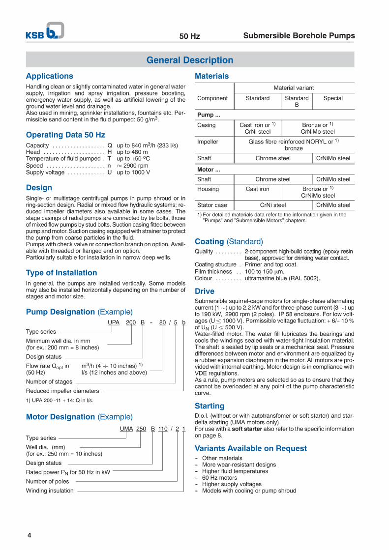
S 100B - 12 ...for well diameters of 100 mm (4 inches) and above
Pumps with submersible motors for ...-- Fluid temperature up + 30 oC. . . . . . . . . . . . . . . . . . . . . . . .-- Type of current / voltage 1µ/230 V. . . . . . . . . . . . . . . . . . .
or 3µ/400 V. . . . . . . . . . . . . . . . . . . . . . . . . . . . . . . . . . . . . .-- Starting d.o.l.. . . . . . . . . . . . . . . . . . . . . . . . . . . . . . . . . . . . . . .
Rated current for Oper-ation
S 100B
Rated-power(motor)PNkW
1 µ230 V
IN 1)
A
3 µ400 V
INA
Typeof in-stalla-tion 2)
ationwithauto-maticcontrolunit 3)
12 / 4 1.1 8.6 3.2 v + h x
12 / 6 1.5 10.6 4.0 v + h x
4)
12 / 10 2.2 15.5 5.9 v + h x
12 / 13 3.0 ------ 7.8 v + h
12 / 17 3.7 ------ 9.1 v x 3)
12 / 21 5.5 ------ 13.7 v ------
12 / 25 5.5 ------ 13.7 v ------
1) Capacitor run motors (PSC motors) with starter.2) v = vertical and h = angled / horizontal.3) Always check and make sure that the operating pressure of Controlmatic /
Cervomatic units is not exceeded.4) 3~ only
Dimensions / Weights / Ident. Numbers / Horizontal Installation1µ / 230 V 3µ / 400 V
S 100BLA
¶ mmmA¶ kg
Ident. No. A¶ mm
LA¶ mm
mA¶ kg
Ident. No. A¶mm
C
12 / 412 / 612 /1012 /1312 /1712 /2112 /25
86510001295-- -- ---------- -- --------
17,319.324.6-- -- ---------- -- --------
39 019 22339 019 22439 019 225
-- -- ---------- -- --------
613739991-- -- ---------- -- --------
80594511951425181521852400
14.716.920.024.232.240.242.0
39 019 27339 019 27439 019 27539 019 27639 019 27739 019 27839 019 279
5857079381135-------- -- --------
G 2”
Accessories: UPA Control for dry running protection by means of 3 immersionelectrodes; see page 20.
x 4)
+

50 Hz S 100B
19
Scope of Supply for Single-phase A.C.Motors DN 100 (1 µµµµ)Astart box for single-phasePSCmotors (with integrated run ca-pacitor and motor protection) is included in the scope of supply.
Permissible Cable Lengths∆U up to 3 %, d.o.l. starting and T up to + 30 oC
Type ofcurrent/Voltage
Motorrating
Cable lengths forcable cross-section in ... mm2
VoltagekW 1.5 2.5 4.0 6.0
1µ/230 V(PSC)
0.370.550.751.101.502.20
72 m60 m47 m30 m26 m20 m
120 m100 m79 m50 m43 m32 m
190 m159 m125 m80 m68 m52 m
284 m236 m186 m118 m101 m77 m
3µ/400 V
0.370.550.751.101.502.203.003.705.50
752 m483 m368 m242 m194 m131 m100 m80 m55 m
----
614 m403 m322 m218 m165 m135 m90 m
------
645 m516 m350 m265 m215 m143 m
----------
525 m397 m323 m215 m
Technical Data - Cooling ShroudS 100 Type of
currentDis-chargenozzle
Ident. No. Overall lengthin mmShroud + suctionstrainer
B 1/7B 1/9B 1/12B 1/14B 1/16B 1/20
1~ / 3~1~ / 3~1~ / 3~1~ / 3~1~ / 3~1~ / 3~
1 1/41 1/41 1/41 1/41 1/41 1/4
39 021 05439 021 05539 021 05639 021 05739 021 05839 021 060
6807158408358841010
B 2/7B 2/11B 2/15B 2/18B 2/20B 2/22
B 2/27
1~ / 3~1~ / 3~1~ / 3~1~ / 3~1~ / 3~1~3~1~3~
1 1/41 1/41 1/41 1/41 1/41 1/41 1/41 1/41 1/4
39 021 05439 021 05639 021 05839 021 06039 021 06139 021 06239 021 06139 021 06439 021 063
680840884101010541112105412701180
B 4/4B 4/6B 4/9B 4/12
B 4/17
B 4/22
1~ / 3~1~ / 3~1~ / 3~1~3~1~3~1~3~
1 1/41 1/41 1/41 1/41 1/41 1/41 1/41 1/41 1/4
39 020 67939 021 05439 021 05639 021 05839 021 05939 021 06239 021 06139 021 06439 021 063
5976808408849341112105412701180
B 7/5B 7/7B 7/9B 7/12
B 7/14
B 7/19
1~ / 3~1~ / 3~1~ / 3~1~3~1~3~3~
1 1/41 1/41 1/41 1/41 1/41 1/41 1/41 1/4
39 021 05539 021 05639 021 05739 021 06239 021 06139 021 06339 021 06239 021 065
75584083511121054118011121363
B 12/4
B 12/6
B 12/10
1~3~1~3~
1~ / 3~
22222
39 021 06639 020 74539 021 06839 021 06739 021 069
884835105410101363

50 Hz S 100B
20
Accessories: UPA Control for Dry Running Protection (Using 3 Immersion Electrodes)
S 100B-1/.. 1~~~~ S 100B-1/... 3~~~~
RelayTéléméca-nique(A )
Electrode(Qty.)
7912
141620
2530
3540 50 Ident. No.
RelayTéléméca-nique(A )
Electrode(Qty.)
7912
1416202730
354050 Ident. No.
2.5 to 4.0 ( 3 ) X 40 980 891 1.0 to 1.6 ( 3 ) X 40 980 887
4.0 to 6.0 ( 3 ) X 40 980 893 1.6 to 2.5 ( 3 ) X 40 980 889
5.5 to 8.0 ( 3 ) X 40 990 895 2.5 to 4.0 ( 3 ) X 40 980 891
7.0 to 10 ( 3 ) X 40 980 897
9.0 to 13 ( 3 ) X 40 980 899
S 100B-2/.. 1~~~~ S 100B-2/... 3~~~~
RelayTéléméca-nique(A )
Electrode(Qty.) 7 11 15
182022
2730
333844 Ident. No.
RelayTéméca-nique(A )
Electrode(Qty.) 7
1115
18bis30
334450 Ident. No.
2.5 to 4.0 ( 3 ) X 40 980 891 1.0 to 1.6 ( 3 ) X 40 980 887
4.0 to 6.0 ( 3 ) X 40 980 893 1.6 to 2.5 ( 3 ) X 40 980 889
5.5 to 8.0 ( 3 ) X 40 990 895 2.5 to 4.0 ( 3 ) X 40 980 891
7.0 to 10 ( 3 ) X 40 980 897 5.5 to 8.0 ( 3 ) X 40 980 895
9.0 to 13 ( 3 ) X 40 980 899
12 to 18 ( 3 ) X 40 984 811
S 100B-4/.. 1~~~~ S 100B-4/... 3~~~~
RelayTéléméca-nique(A )
Electrode(Qty.) 4 6 9 12 17
2225 Ident No.
RelayTéléméca-nique(A )
Electrode(Qty.) 4
69
1217
2225
3542 Ident No.
2.5 to 4.0 ( 3 ) X 40 980 891 1.0 to 1.6 ( 3 ) X 40 980 887
4.0 to 6.0 ( 3 ) X 40 980 893 1.6 to 2.5 ( 3 ) X 40 980 889
5.5 to 8.0 ( 3 ) X 40 990 895 2.5 to 4.0 ( 3 ) X 40 980 891
7.0 to 10 ( 3 ) X 40 980 897 5.5 to 8.0 ( 3 ) X 40 980 895
9.0 to 13 ( 3 ) X 40 980 899 7.0 to 10 ( 3 ) X 40 980 897
12 to 18 ( 3 ) X 40 984 811
S 100B-7/.. 1~~~~ S 100B-7/... 3~~~~
RelayTéléméca-nique(A )
Electrode(Qty.) 5 7 9
1214 Ident No.
RelayTéléméca-nique(A)
Electrode(Qty.) 5
79
121419 25
3035 Ident No.
5.5 to 8.0 ( 3 ) X 40 990 895 1.6 to 2.5 ( 3 ) X 40 980 889
7.0 to 10 ( 3 ) X 40 980 897 2.5 to 4.0 ( 3 ) X 40 980 891
9.0 to 13 ( 3 ) X 40 980 899 5.5 to 8.0 ( 3 ) X 40 980 895
12 to 18 ( 3 ) X 40 984 811 7.0 to 10 ( 3 ) X 40 980 897
12 to 18 ( 3 ) X 40 984 811
S 100B-12/.. 1~~~~ S 100B-12/... 3~~~~
RelayTéléméca-nique(A )
Electrode(Qty.) 4 6 10 Ident No.
RelayTéléméca-nique(A )
Electrode(Qty.)
46 10
1317
2125 Ident No.
7.0 to 10 ( 3 ) X 40 980 897 2.5 to 4.0 ( 3 ) X 40 980 891
9.0 to 13 ( 3 ) X 40 980 899 5.5 to 8.0 ( 3 ) X 40 980 895
12 to 18 ( 3 ) X 40 984 811 7.0 to 10 ( 3 ) X 40 980 897
12 to 18 ( 3 ) X 40 984 811

UPA150S50 Hz
21
Submersible Borehole Pumps for UPA150SWell Diameters of 150 mm (6 Inches) and Above
Selection Chart 50 Hz (Ranges on Offer) n ≈ 2880 rpm
Note: The diagram shows the ∆QA range on offer. The pumps can be offered for any duty point within this range. The operatingranges∆QB of the individual pump sizes are given in the characteristic curves for different stage numbers on the following pages.