
Catalogo Fisher LP 31 Ingles
84
LP-Gas Equipment Buyers Guide LP-31 The Industry Leader for Durability and Quality
Transcript of Catalogo Fisher LP 31 Ingles

LP-Gas Equipment Buyers GuideLP-31The Industry Leader for Durability and Quality

Fisher® LP-Gas EquipmentGlobal Technology Leadership
Our commitment to providing customers with customized solutions, dependable products, along with uncompromising quality standards and exceptional service is a tradition dating back to our beginnings in 1880, when William Fisher invented the fi rst regulator. Today, Fisher LP-Gas Equipment is a part of Emerson Process Management’s Regulator Technologies Division, the World Leader in valve and regulator design and manufacturing. Emerson, a $20.9 billion company, invests over $400 million in research and development annually. Being a part of Emerson provides Fisher LP-Gas Equipment with the resources of a Global Technology Leader.
Commitment to the LP-Gas Industry
With a focus on Safety and Reliability, Fisher LP-Gas Equipment continues a tradition of delivering innovative, high performance products utilizing the latest technologies. From the development of the fi rst rubber diaphragm for regulators by Fisher in 1928 to the development of the fi rst true internal valve in 1959, we proudly continue this tradition by introducing our new line of Jet Bleed InternalTM Valves, as well as our expanded line of commercial service regulators, providing the broadest line of regulator products offered in the LP-Gas industry today.
Commitment to our Customers
In addition to continually developing improved products for our customers, we are active in promoting and supporting the industry. Through our role in world and national organizations, we continue to promote increased safety throughout the entire industry.
Laboratory Tests Simulate Field Conditions
Domestic Regulators
Commercial/Industrial Regulators
Bulk Storage and Transportation Equipment

1
REGULATOR APPLICATION MAP . . . . . . . . . . . . . . . . . . . . . . . . . 2
VALVE APPLICATION MAP . . . . . . . . . . . . . . . . . . . . . . . . . . . . . . . 4
REGULATOR SELECTION GUIDE . . . . . . . . . . . . . . . . . . . . . . . . . 6
VALVE SELECTION GUIDE . . . . . . . . . . . . . . . . . . . . . . . . . . . . . 11
ACCESSORIES SELECTION GUIDE . . . . . . . . . . . . . . . . . . . . . . 16
TWO–STAGE SYSTEMS . . . . . . . . . . . . . . . . . . . . . . . . . . . . . . . 23
FIRST–STAGE REGULATORS . . . . . . . . . . . . . . . . . . . . . . . . . . . 24Types R122H, R622H
SECOND–STAGE REGULATORS . . . . . . . . . . . . . . . . . . . . . . . . 25Types HSRL, R222, R622, R642, R652
2–psi SERVICE REGULATORS . . . . . . . . . . . . . . . . . . . . . . . . . . 26Types R622E, R652E
INTEGRAL TWO–STAGE REGULATORS . . . . . . . . . . . . . . . . . . 27Types R232, R632
AUTOMATIC CHANGEOVER REGULATORS . . . . . . . . . . . . . . . 28Types 64SR, 749B, 803, R110, R130, R962
COMMERCIAL/INDUSTRIAL HIGH PRESSURE REGULATORS . . . . . . . . . . . . . . . . . . . . . . . . 30
Types 67CW, 67CH, 67CD, 67CN, 64, 64SR, 627, 630, 1301F, 99, 1098-EGR
COMMERCIAL LOW PRESSURE REGULATORS . . . . . . . . . . . . . . . . . . . . . . . . . . . . . . . .36 to 37, 40
Types CS200, CS400, CS800, 133L, 133H, 299H, 99L
COMMERCIAL SERVICE OVERPRESSURE PROTECTION . . . . 38Types CS205, CS206, CS403, CS404
MONITOR OVERPRESSURE PROTECTION . . . . . . . . . . . . . . . . 41
Types 627M, 99M, 1098
BACKPRESSURE REGULATORS/RELIEF VALVES . . . . . . . . . . 42Types 98H, 289H, 1805
REGULATOR ACCESSORIES . . . . . . . . . . . . . . . . . . . . . . . .43
INTERNAL VALVES . . . . . . . . . . . . . . . . . . . . . . . . . . . . . . . . . .46Types C407, C471, C477, C483, C484
Where applicable, Fisher® brand products presented in this catalog are listed by Underwriters Laboratories (UL). Use of these products may provide compliance with standards developed by the National Fire Protection Association’s Pamphlets 54 and 58. They may also assist in meeting guidelines established by the Department of Transportation, ASME, and other third party agencies. Contact your Fisher brand LP-Gas Regulators and Equipment Distributor for assistance in determining product applications.
INTERNAL VALVE ACCESSORIES . . . . . . . . . . . . . . . . . . . . . . 58P Series Actuators
EMERGENCY SHUTOFF VALVES . . . . . . . . . . . . . . . . . . . . . . . . . 60Types N550, N562
EXCESS FLOW VALVES . . . . . . . . . . . . . . . . . . . . . . . . . . . . . . . 63Types F100, F130, F170, F190, F202
INTERNAL/EXTERNAL RELIEF VALVES . . . . . . . . . . . . . . 64 to 65Types H110, H120, H123, H124, H125, H144, H148, H150, H173, H174, H185, H282, H722, H732, H5112
GLOBE AND ANGLE VALVES . . . . . . . . . . . . . . . . . . . . . . . . . . . . 66Types N301, N310, N310F, N350, N401, N410, N410F, N450
BACK CHECK VALVES . . . . . . . . . . . . . . . . . . . . . . . . . . . . . . . . . 67Types G100, G101, G102, G104, G105, G106, G107,G109, G112, G200, G201
HOSE END, FILLER AND LIQUID TRANSFER VALVES . . . . . . . 68Types D138, D139, D140, D141, M455, N456, N480, N481
BYPASS AND BACKPRESSURE VALVES . . . . . . . . . . . . . . . . 69Types N100, N110, N120
LIQUID LEVEL INDICATORS . . . . . . . . . . . . . . . . . . . . . . . . . . . . 71Types J31, J402S, J403S, J415, J415-1, J700
COUPLINGS AND ADAPTORS . . . . . . . . . . . . . . . . . . . . . . . . . . 72M Series, Types P174, P104-24
MISCELLANEOUS EQUIPMENT . . . . . . . . . . . . . . . . . . . . . . . 75
COMPLIANCE SYSTEMS. . . . . . . . . . . . . . . . . . . . . . . . . . . 77
LITERATURE . . . . . . . . . . . . . . . . . . . . . . . . . . . . . . . . . . . . . . . . . 78
CONVERSION FACTORS . . . . . . . . . . . . . . . . . . . . . . . . . . . . . . . 79
INDEX . . . . . . . . . . . . . . . . . . . . . . . . . . . . . . . . . . . . . . . . . . . . . . 80
TABLE OF CONTENTS
National PROPANE GAS Association
NPGAMEMBER
R

2
R642Second-
Stage
Page 25 Page 30
67CWHigh-
Pressure
R622Second- Stage
Page 25 Page 24
R622HFirst-Stage
R222Second-Stage
Page 25
R232Integral
Two-Stage
R632IntegralTwo-Stage
Page 27
Page 36 Page 32Page 27
CS800Second- Stage
630First-Stage
R622Second- Stage
First-Stage
R122H
Page 25
Page 34 Page 40 Page 35
Page 36
Page 36
Page 36
Page 32 Page 25
Page 36
Page 36
Page 24
99First-Stage
Page 40
299HSecond-Stage
1098First-Stage
CS400Second-Stage
CS403Second-Stage
Monitor
CS404Second-Stage UPSO/OPSO
Shutoff
627First-Stage Second-StageHSRL
Second- Stage
CS400
CS200Second-Stage
642ond-age e
R622Second- Stage
R622Second- Stage
622Hirst-tage
R222econd-age
-e
First-Stage
F
R632IntegralTwo-Stage
Page 27
CS800Second- Stage
P 32
63First-S
IntegralTwo-Stage
Page 36
CS400econd-Stage
Page 36
econd-Stage
S400
Page 36
Second-Stage Monitor
Page 36
gUPSO/OPSO
Shutoff Page 32
627First-Stage
Page 25
Second-StageHSRL
Page 36
Second-Stage
Features*Features*
• Corrosion-Resistant and Wear-Resistant Materials • Stainless Steel Inlet Screen • Large Drip-Lip Vent • High Capacity Relief • Easy Installation • Improved Regulation • Built-in Gauge Taps
*Features Vary By Model.
IntroductionThe regulator truly is the heart of an LP-Gas installation. It must compensate for variations in tank pressure from 8 to 250 psig / 0,55 to
Application: Regulators
LP-GAS REGULATORS

3
R642Second-
Stage
Page 25 Page 30
67CWHigh-
Pressure
R622Second- Stage
Page 25 Page 24
R622HFirst-Stage
R222Second-Stage
Page 25
R232Integral
Two-Stage
R632IntegralTwo-Stage
Page 27
Page 36 Page 32Page 27
CS800Second- Stage
630First-Stage
R622Second- Stage
First-Stage
R122H
Page 25
Page 34 Page 40 Page 35
Page 36
Page 36
Page 36
Page 32 Page 25
Page 36
Page 36
Page 24
99First-Stage
Page 40
299HSecond-Stage
1098First-Stage
CS400Second-Stage
CS403Second-Stage
Monitor
CS404Second-Stage UPSO/OPSO
Shutoff
627First-Stage Second-StageHSRL
Second- Stage
CS400
CS200Second-Stage
642ond-age e
R622Second- Stage
R622Second- Stage
622Hirst-tage
R222econd-age
-e
First-Stage
F
R632IntegralTwo-Stage
Page 27
CS800Second- Stage
P 32
63First-S
IntegralTwo-Stage
Page 36
CS400econd-Stage
Page 36
econd-Stage
S400
Page 36
Second-Stage Monitor
Page 36
gUPSO/OPSO
Shutoff Page 32
627First-Stage
Page 25
Second-StageHSRL
Page 36
Second-Stage
*R622E and R652E are green with white closing caps
Fisher Regulator Color Code
First-Stage ..........................................RedSecond-Stage .....................................Palm Green2-PSI Service ......................................White*Integral Two-Stage ..............................GrayPounds to Pounds ...............................RedIndustrial ............................................Black or Gray
17,2 bar and deliver a constant outlet pressure of LP-Gas typically at 11-inches w.c. / 27 mbar to consuming appliances. The regulator must deliver this pressure despite the intermittent use of the appliances.
In propane service, NFPA 58 requires Two-Stage regulation on all fixed piping systems that serve 14-inches w.c. / 35 mbar appliance systems (normally operated at 11-inches w.c. / 27 mbar pressure). Two-Stage regulation produces a nearly
constant pressure to the appliance and can result in a more efficient LP-Gas operation for the dealer resulting in less maintenance and fewer installation call-backs.
With properly selected regulators, the internal relief valve provides 2 psig / 0,14 bar overpressure protection as required by NFPA 58.
Emerson Process Management Regulator Technologies Inc. (Regulator Technologies) is a
leading international supplier of cost-effective products, services, and solutions used in the propane industry. Around the world, Regulator Technologies and its distributors offer quality products as well as applications engineering, education programs, and after sales service. For any of the products described in this catalog, contact the Fisher® LP-Gas Equipment distributor near you.
LP-GAS REGULATORS

4
P539A
Page 60
Page 47
Page 64
Page 52
Page 60
Page 52 Page 47
Page 64
Page 60
Page 67
Page 66
Page 66
Page 64
Page 54
Page 62
PneumaticActuator
C407-10InternalValve withP631Actuator
H722Relief Valve
Jet Bleed Internal™
Valve
C483-24
Jet Bleed Internal™
Valve
C484-24J
C477Jet Bleed Internal™
Valve
ed™
N550Emergency
Shutoff Valve
H282Relief Valve
N562Emergency Shutoff Valve
N550 with P327DEmergency Shutoff Valve
G201Back Check Valve
N310-10GlobeValve
Internal Valvewith P614
Actuator
C404-32
H732Relief Valve
N410-10AngleValve
P
N55Eme
Shu
P539A
Page 60
PneumaticActuator
H282Relief Valve
Internal Valvewith P614
Actuator
LP-GAS VALVES
Application:Valves and Relief Valves

5
P539A
Page 60
Page 47
Page 64
Page 52
Page 60
Page 52 Page 47
Page 64
Page 60
Page 67
Page 66
Page 66
Page 64
Page 54
Page 62
PneumaticActuator
C407-10InternalValve withP631Actuator
H722Relief Valve
Jet Bleed Internal™
Valve
C483-24
Jet Bleed Internal™
Valve
C484-24J
C477Jet Bleed Internal™
Valve
ed™
N550Emergency
Shutoff Valve
H282Relief Valve
N562Emergency Shutoff Valve
N550 with P327DEmergency Shutoff Valve
G201Back Check Valve
N310-10GlobeValve
Internal Valvewith P614
Actuator
C404-32
H732Relief Valve
N410-10AngleValve
P
N55Eme
Shu
P539A
Page 60
PneumaticActuator
H282Relief Valve
Internal Valvewith P614
Actuator
Features*
• Truck Relief Valves – All Stainless Steel Construction • High Flow Capacities • Positive Shutoff Valves • Rugged Construction • Ease of Service • Wide Range of Products for Varying Applications
*Features Vary By Model.
LP-GAS VALVES
IntroductionFisher® brand internal valves, relief valves, emergency shutoff valves, and globe and angle valves are installed in the inlets and outlets (liquid or vapor) of pressure vessels and in piping systems to control the fl ow of LP-Gas and NH3 (anhydrous ammonia). These valves are frequently used on bobtails, transport truck tanks, large stationary storage tanks, and in-line installations.
The valves provide a means of withdrawing and fi lling product with or without pumps and compressors. These valves may be used as primary shutoff valves, excess fl ow valves, and back check valves. No one offers a more complete line of LP-Gas Equipment to match your job specifi cation.
6
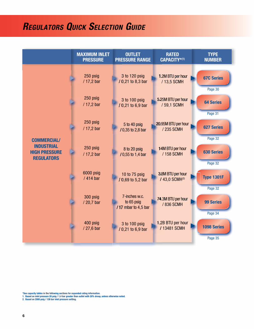
REGULATORS QUICK SELECTION GUIDE
*See capacity tables in the following sections for expanded rating information.1. Based on inlet pressure 20 psig / 1,4 bar greater than outlet with 20% droop, unless otherwise noted. 2. Based on 2000 psig / 138 bar inlet pressure setting.
COMMERCIAL/INDUSTRIAL
HIGH PRESSUREREGULATORS
MAXIMUM INLETPRESSURE
OUTLET PRESSURE RANGE
RATED CAPACITY*(1)
TYPE NUMBER
3 to 120 psig / 0,21 to 8,3 bar
3 to 100 psig / 0,21 to 6,9 bar
5 to 40 psig / 0,35 to 2,8 bar
8 to 20 psig / 0,55 to 1,4 bar
10 to 75 psig / 0,69 to 5,2 bar
7-inches w.c. to 65 psig
/ 17 mbar to 4,5 bar
3 to 100 psig/ 0,21 to 6,9 bar
1.2M BTU per hour / 13,5 SCMH
5.25M BTU per hour / 59,1 SCMH
20.95M BTU per hour / 235 SCMH
14M BTU per hour / 158 SCMH
3.8M BTU per hour / 43,0 SCMH(2)
74.3M BTU per hour / 836 SCMH
1.2B BTU per hour/ 13481 SCMH
250 psig / 17,2 bar
250 psig / 17,2 bar
250 psig / 17,2 bar
250 psig / 17,2 bar
6000 psig / 414 bar
300 psig / 20,7 bar
400 psig / 27,6 bar
64 Series
Page 31
67C Series
Page 30
20.95M BTU per hour
5.25M BTU per hour
1.2M BTU per hour
/ 0,35 to 2,8 bar
3 to 100 psig / 0,21 to 6,9 bar/ 0,21 to 6,9 bar
3 to 120 psig / 0,21 to 8,3 bar/ 0,21 to 8,3 bar
99 Series
Page 34
Type 1301F
Page 32
627 Series
Page 32
630 Series
Page 32
14M BTU per hour / 0,55 to 1,4 bar
3.8M BTU per hour / 43,0 SCMH/ 0,69 to 5,2 bar/ 0,69 to 5,2 bar
74.3M BTU per hour
/ 17 mbar to 4,5 bar / 17 mbar to 4,5 bar
1.2B BTU per hour/ 13481 SCMH/ 0,21 to 6,9 bar/ 0,21 to 6,9 bar 1098 Series
Page 35

7
REGULATORS QUICK SELECTION GUIDE
*See capacity tables in the following sections for expanded rating information.1. Based on inlet pressure 20 psig / 1,4 bar greater than outlet with 20% droop, unless otherwise noted. 2. Based on 10 psig / 0,69 bar inlet pressure setting and 20% droop.3. Based on 10 psig / 0,69 bar inlet pressure setting and 2-inches w.c. / 5 mbar droop.4. Types 912-101 and -104 rating at 30 psig / 2,1 bar inlet.
COMMERCIAL/INDUSTRIAL
LOW PRESSURE REGULATORS
MAXIMUM INLETPRESSURE
OUTLET PRESSURE RANGE
RATED CAPACITY*(1)
TYPE NUMBER
3.5-inches w.c. to 2 psig /
9 mbar to 0,14 bar
3.5-inches w.c. to 5.5 psig /
9 mbar to 0,38 bar
8-inches w.c to 5.5 psig /
20 mbar to 0,38 bar
1.5 to 3 psig / 0,10 to 0,21 bar
8.5 to 18-inches w.c. / 21 to 45 mbar
9-inches w.c. to 16 psig /
22 mbar to 1,1 bar
7-inches w.c. to 5 psig /
18 mbar to 0,35 bar
3-inches w.c. to 5 psig /
7 mbar to 0,35 bar
125 psig / 8,6 bar
125 psig/ 8,6 bar
125 psig/ 8,6 bar
60 psig / 4,1 bar
60 psig / 4,1 bar
150 psig / 10,3 bar
150 psig / 10,3 bar
250 psig / 17,2 bar
3.5-inches w.c.
9 mbar to 0,38 bar
3.5-inches w.c.
9 mbar to 0,14 bar
20 mbar to 0,38 bar 20 mbar to 0,38 bar
1.5 to 3 psig / 0,10 to 0,21 bar
18-inches w.c. / 21 to 45 mbar
22 mbar to 1,1 bar
18 mbar to 0,35 bar
7 mbar to 0,35 bar
299H Series
Page 40
99-500P Series
Page 40
Type 133H
Page 40
CS800 Series
Page 36
Type 133L
Page 40
CS200 Series
Page 36
CS400 Series
Page 36
912 Series
Page 43
3.9M BTU per hour / 43,8 SCMH(3)
8.9M BTU per hour / 100 SCMH(2)
20M BTU per hour/ 224 SCMH
66.15M BTU per hour / 745 SCMH(2)
70.8M BTU per hour/ 797 SCMH(3)
38M BTU per hour / 428 SCMH
63.25M BTU per hour/ 712 SCMH
556 000 BTU per hour / 6,2 SCMH(4)

8
REGULATORS QUICK SELECTION GUIDE
*See capacity tables in the following sections for expanded rating information.1. Based on 30 psig / 2,1 bar inlet pressure and 20% droop.2. Based on 10 psig / 0,69 bar inlet pressure setting.3. Second-Stage regulators are UL rated.
FIRST-STAGE REGULATORS
MAXIMUM INLETPRESSURE
OUTLET PRESSURE SETTING/SETPOINTS
RATED CAPACITY*(1)
TYPE NUMBER
10 psig / 0,69 bar +/- 1 psig / 69 mbar nominal outlet setting
(non-adjustable)
5 or 10 psig / 0,35 or 0,69 bar standard setpoints
250 psig / 17,2 bar
250 psig / 17,2 bar
R122H Series
Page 24
R622H Series
Page 25
/ 0,35 or 0,69 bar standard setpoints
+/- 1 psig / 69 mbar +/- 1 psig / 69 mbar nominal outlet setting nominal outlet setting
SECOND-STAGE REGULATORS(3)
MAXIMUM INLETPRESSURE
STANDARD SETPOINT
RATED CAPACITY*(2)
TYPE NUMBER
9 to 13-inches w.c. / 22 to 32 mbar
11-inches w.c. / 27 mbar
11-inches w.c. / 27 mbar
11-inches w.c. / 27 mbar
11-inches w.c. / 27 mbar
2.6M BTU per hour / 29,3 SCMH
650 000 BTU per hour / 7,3 SCMH
1.4M BTU per hour / 15,8 SCMH
920 000 BTU per hour/ 10,4 SCMH
1M BTU per hour / 11,2 SCMH
10 psig / 0,69 bar
10 psig / 0,69 bar
10 psig / 0,69 bar
10 psig / 0,69 bar
10 psig / 0,69 bar
R222 Series
Page 25
1.4M BTU per hour 1.4M BTU per hour 11-inches w.c.
11-inches w.c.
R622 Series
Page 25
11-inches w.c.
1M BTU per hour 11-inches w.c.
R642 Series
Page 25
R652 Series
Page 25
Type HSRL
Page 25
2.6M BTU per hour 2.6M BTU per hour 9 to 13-inches w.c. / 22 to 32 mbar
1.1M BTU per hour/ 12,4 SCMH
2.4M BTU per hour / 27,0 SCMH
9
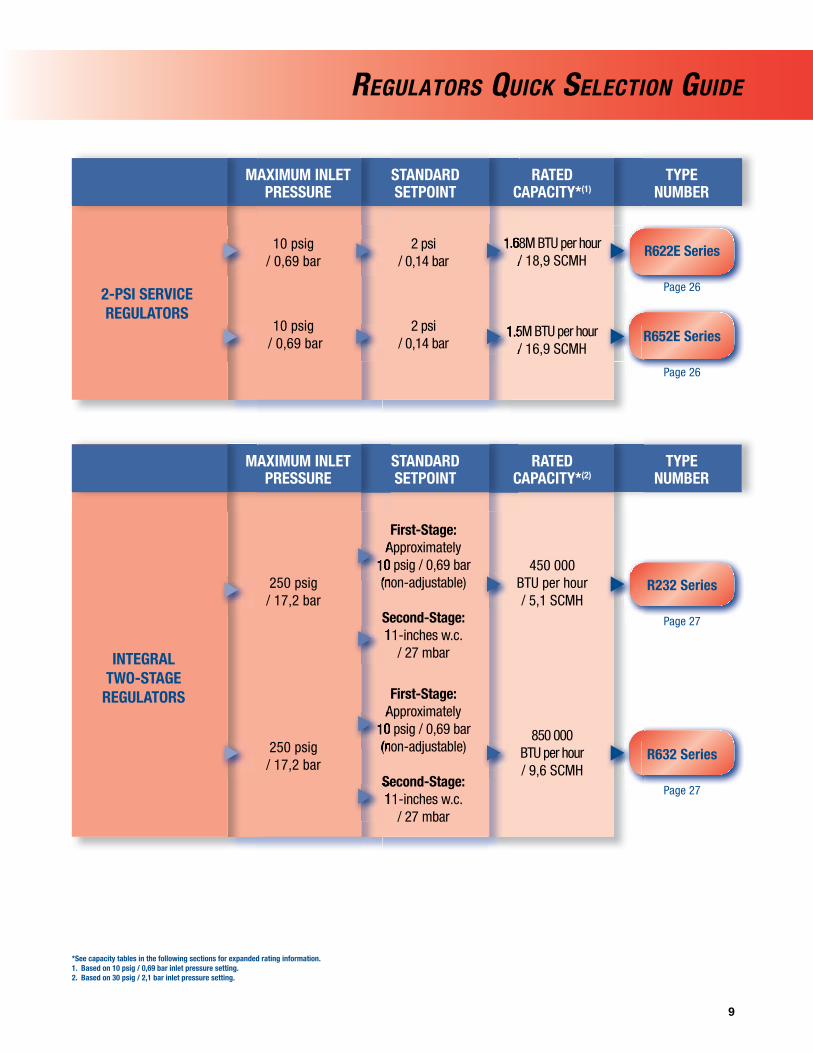
REGULATORS QUICK SELECTION GUIDE
*See capacity tables in the following sections for expanded rating information.1. Based on 10 psig / 0,69 bar inlet pressure setting.2. Based on 30 psig / 2,1 bar inlet pressure setting.
2-PSI SERVICE REGULATORS
MAXIMUM INLETPRESSURE
STANDARD SETPOINT
RATEDCAPACITY*(1)
TYPE NUMBER
2 psi / 0,14 bar
2 psi / 0,14 bar
1.68M BTU per hour / 18,9 SCMH
1.5M BTU per hour / 16,9 SCMH
10 psig / 0,69 bar
10 psig / 0,69 bar
R622E Series
Page 26
1.5M BTU per hour 1.5M BTU per hour / 16,9 SCMH
1.68M BTU per hour 1.68M BTU per hour / 18,9 SCMH
R652E Series
Page 26
INTEGRAL TWO-STAGE
REGULATORS
MAXIMUM INLETPRESSURE
STANDARD SETPOINT
RATEDCAPACITY*(2)
TYPE NUMBER
First-Stage: Approximately
10 psig / 0,69 bar (non-adjustable)
Second-Stage: 11-inches w.c.
/ 27 mbar
First-Stage: Approximately
10 psig / 0,69 bar (non-adjustable)
Second-Stage: 11-inches w.c.
/ 27 mbar
250 psig / 17,2 bar
250 psig / 17,2 bar
R232 Series
Page 2711-inches w.c.
Approximately 10 psig / 0,69 bar 10 psig / 0,69 bar (non-adjustable)(non-adjustable)
R632 Series
Page 27
Approximately 10 psig / 0,69 bar 10 psig / 0,69 bar (non-adjustable)(non-adjustable)
Second-Stage: 11-inches w.c.
450 000 BTU per hour / 5,1 SCMH
850 000 BTU per hour/ 9,6 SCMH

10
REGULATORS QUICK SELECTION GUIDE
BACKPRESSUREREGULATORS/RELIEF VALVES
MAXIMUM WORKINGPRESSURE
RELIEF PRESSURE SETTING
RELIEFCAPACITY*
TYPE NUMBER
100 psig / 6,9 bar
15 psig / 1,0 bar
30 psig / 2,1 bar
93.1 GPM / 352 l/min Propane
20 000 SCFH / 566 SCMH Propane
12 000 SCFH / 340 SCMH Propane
300 psig / 20,7 bar
25 psig / 1,7 bar
150 psig / 10,3 bar
Type 98H
Page 42
/ 352 l/min Propane/ 352 l/min Propane
Type 289H
Page 42
Type 1805
Page 42
/ 566 SCMH Propane/ 566 SCMH Propane
/ 340 SCMH Propane/ 340 SCMH Propane
*See capacity tables in the following sections for expanded rating information.

11
*See capacity tables in the following sections for expanded rating information.
VALVES AND RELIEF VALVES QUICK SELECTION GUIDES
INTERNAL/EXTERNAL RELIEF VALVES
STANDARD SETPOINTS
MAXIMUM INLET PRESSURE
(BODY RATING)CAPACITY*
TYPE NUMBER
480 psig / 33,1 bar
480 psig / 33,1 bar
420 psig/ 29,0 bar
UL: 12 220 SCFM / 20 764 SCMH Air
ASME: 10 651 SCFM / 18 097 SCMH Air
UL: 11 736 SCFM / 19 940 SCMH AirASME: 9669 SCFM / 16 400 SCMH Air
Up to 2456 SCFM / 4173 SCMH
125 to 312 psig/ 8,6 to 21,5 bar
125 to 312 psig/ 8,6 to 21,5 bar
35 to 350 psig / 2,4 to 23,8 bar
Fixed Setting
H282 andH5112 Series
Page 64
10 651 SCFM
/ 19 940 SCMH Air/ 19 940 SCMH AirASME: ASME: / 16 400 SCMH Air/ 16 400 SCMH Air
/ 20 764 SCMH Air/ 20 764 SCMH AirASME:ASME:
125 to 312 psig/ 8,6 to 21,5 bar/ 8,6 to 21,5 bar
125 to 312 psig/ 8,6 to 21,5 bar/ 8,6 to 21,5 bar
H722 and H732 Series
Page 64
BYPASS AND BACKPRESSURE
VALVES
MAXIMUM WORKINGPRESSURE
DIFFERENTIAL / RELIEF PRESSURE
SETTING
BODY SIZE AND END CONNECTION STYLE
TYPE NUMBER
50 psig / 0,83 bar or 100 psig /
6,9 bar Setting
12 psig / 0,83 barSetting
1/2, 3/4, and 1-inch FNPT
3/4 and 1-inch FNPT
300 psig/ 20,7 bar
400 psig/ 27,6 bar
N120 Series
Page 70
98 Series
Page 42
50 psig / 0,83 bar 50 psig / 0,83 bar
6,9 bar Setting
12 psig / 0,83 bar12 psig / 0,83 bar
H-100 Series
Page 65
35 to 350 psig / 2,4 to 23,8 bar/ 2,4 to 23,8 bar

12
*See capacity tables in the following sections for expanded rating information.
VALVES AND RELIEF VALVES QUICK SELECTION GUIDES
INTERNAL VALVES
PRESSURE RATING
EXCESS FLOW SPRING CAPACITY*
TYPE NUMBER
30 to 80 GPM / 113 to 302 l/min
60 to 460 GPM / 227 to 1741 l/min
100 to 460 GPM / 379 to 1741 l/min
160 to 400 GPM / 606 to 1514 l/min
160 to 400 GPM / 606 to 1514 l/min
340 to 1000 GPM/ 1287 to
3785 l/min
19 200 SCFH / 544 SCMH
Propane
178 000 SCFH / 5040 SCMH
Propane
178 000 SCFH / 5040 SCMH
Propane
190 000 SCFH / 5380 SCMH
Propane
190 000 SCFH / 5380 SCMH
Propane
356 200 SCFH / 10 088 SCMH
400 psig / 27,6 bar WOG
400 psig / 27,6 bar WOG
400 psig / 27,6 bar WOG
400 psig / 27,6 bar WOG
400 psig / 27,6 bar WOG
400 psig/ 27,6 bar
178 000 SCFH / 5040 SCMH/ 27,6 bar WOG
/ 27,6 bar WOG
100 to 460 GPM / 379 to 1741 l/min/ 379 to 1741 l/min
/ 113 to 302 l/min/ 113 to 302 l/min
178 000 SCFH / 5040 SCMH / 27,6 bar WOG
60 to 460 GPM / 227 to 1741 l/min/ 227 to 1741 l/min
C407-10 Series
Page 47
C471-16, -24 Jet Bleed
Internal™ Series
Page 47
190 000 SCFH / 5380 SCMH / 27,6 bar WOG
160 to 400 GPM / 606 to 1514 l/min/ 606 to 1514 l/min
/ 5380 SCMH
/ 10 088 SCMH
/ 27,6 bar WOG160 to 400 GPM
/ 606 to 1514 l/min/ 606 to 1514 l/min
340 to 1000 GPM340 to 1000 GPM
C477-16, -24 Jet Bleed
Internal™ Series
Page 47
C483-24 Jet Bleed
Internal™ Series
Page 52
C484-24 Jet Bleed
Internal™ Series
Page 52
Type C404-32
Page 54

13
VALVES AND RELIEF VALVES QUICK SELECTION GUIDES
BACK CHECK VALVES
SEAT CONSTRUCTION
PRESSURE RATING
CAPACITY* TYPE NUMBER
250 psi / 17,2 bar
400 psig / 27,6 bar WOG
254 GPM / 961 l/min
Propane
800 GPM / 3028 l/min
Propane
Soft Seat and Metal Seat
Soft Seat
G100 Series
Page 67
G200 Series
Page 67
/ 27,6 bar WOG
*See capacity tables in the following sections for expanded rating information.
EMERGENCY SHUTOFF VALVES
BODY SIZES AND END CONNECTION STYLE
MAXIMUM INLET PRESSURE
CAPACITY* TYPE NUMBER
400 psig / 27,6 bar
400 psig / 27,6 bar
275 GPM / 1041 l/min
Propane
200 GPM / 757 l/min Propane
1-1/4, 2, or 3-inch FNPT
2-inch FNPT
N550 Series
Page 60
N562 Series
Page 62

14
GLOBE AND ANGLE VALVES
TYPE NUMBER
400 psig / 27,6 bar
400 psig / 27,6 bar
400 psig / 27,6 bar
400 psig / 27,6 bar
1/2 to 3-inch FNPT
and 3-inch / DN 80CL300 RF Flange
1/2 to 3/4-inch FNPT
1/2 to 3-inch FNPT and 3-inch / DN 80CL300 RF Flanged
1/2 to 3/4-inch FNPT
Globe Valve (Heavy Duty
Version)
Globe Valve (Economy Version)
Angle Valve (Heavy Duty
Version)
Angle Valve (Economy Version)
N301, N310Series
Page 66
1/2 to 3-inch FNPT and 3-inch / DN 80CL300 RF Flanged
and 3-inch / DN 80
N350 Series
Page 66
N401, N410 Series
Page 66
N450 Series
Page 66
BODY SIZES AND END
CONNECTION STYLESCONNECTION STYLES
MAXIMUM OPERATING PRESSURE
SELECTION DESCRIPTION
SELECTION DESCRIPTION
VALVES AND RELIEF VALVES QUICK SELECTION GUIDES
*See capacity tables in the following sections for expanded rating information.

15
VALVES
PRODUCT/FUNCTION
SELECTION INFORMATION
TYPE NUMBER
Excess Flow Valve
Filler Valve
Hose End Valve
Bypass Valves
Cylinder Filling Valve
Brass or Steel body in a variety of Inlet and Outlet Connection Sizes
and Styles; Up to 10.7 psi / 0,74 bar differential pressure
2-inch MNPT x 2-1/4-inch ACME or 3-inch MNPT x 3-1/4-inch ACME;
Single or Double Back Check style; 275 GPM / 1041 l/min filling capacity
1-3/4-inch ACME x 1-inch NPT; Ductile iron body
1 through 2-1/2-inch FNPT; 25 to 150 psig / 1,7 to 10,3 bar Pressure
range; 40 GPM / 151 l/min pumping capacity
30 psig / 2,1 bar Recommended Supply Pressure; Aluminum Body
D Series
Page 68
and Styles; Up to 10.7 psi / 0,74 bar Excess Flow Valve
3-inch MNPT x 3-1/4-inch ACME; Single or Double Back Check style;
F Series
Page 63
Supply Pressure; Aluminum BodyCylinder Filling Valve
N100 Series
Page 69
Type N201
Page 76
VALVES AND RELIEF VALVES QUICK SELECTION GUIDES
Type N480
Page 68
*See capacity tables in the following sections for expanded rating information.

16
REGULATOR ACCESSORIES
PRODUCT/FUNCTION
SELECTION INFORMATION
TYPE NUMBER
1/4-Inch FNPT to1-Inch MNPT
Triangular, Bowtie, or Strap Design
Male POL x Female POL, Test block with 0 to 300 psig
/ 0 to 20,7 bar gauge.
1/4-Inch NPT or Female Hose
1/4-Inch MNPT; 0 to 400 psi / 0 to 27,6 bar;
Ranges in MPa, kg/cm2, Bar
Drill Size No. 80 through No. 50
Screened Vents for Regulator
Regulator Mounting Brackets
Pressure Gauge Adaptorand Test Block
Test Pressure Gauge forAppliance Line Pressure
Pressure Gauge
Adjustable OrificeReamer
Pressure Gauge AdaptorMale POL x Female POL,
Test block with 0 to 300 psig Test block with 0 to 300 psig
Test Pressure Gauge forAppliance Line Pressure
0 to 400 psi / 0 to 27,6 bar; 0 to 400 psi / 0 to 27,6 bar;
LP-GAS EQUIPMENT AND ACCESSORIES
Y602 Series
Page 43
50 Series
Page 45
J500 Series
Page 45
Type P100
Page 44
Type J600
Page 44
Type P520L
Page 76

17
BULK STORAGE TANK AND VALVE
ACCESSORIES
PRODUCT/FUNCTION
SELECTION INFORMATION
TYPE NUMBER
3/4 by 3/4-Inch MNPT
68 to 140-Inch/ 1727 to 3556 mm
Lengths
3/4-Inch MNPT for FNPT Connection; with or
without Pressure Gauge
1/2-Inch MNPT; -40° to 120°F / -40° to 49°C
1-1/4 by 1-1/4-Inch through 4-1/4 by
4-1/4-Inch Male ACME
1-3/4-Inch Female ACME by 1/2-Inch MNPT through 4-1/4-Inch Female ACME
by 3-Inch MNPT
1-3/4-Inch Female ACME by 3/4-Inch MNPT through 2-1/4-Inch Female ACME
by 1-1/4-Inch MNPT
Liquid Transfer Valve
Rotary Level Gauge forStational or Mobile Tank
Liquid Level Vent Valves
Container (Tank)Thermometer
Male ACME Adaptor
Female ACME Filler Couplings
Female ACME VaporReturn Couplings
Type M455
Page 68
Liquid Level Vent Valves without Pressure Gauge without Pressure Gauge
Type J31
Page 71
Stational or Mobile Tank
J400 Series
Page 71
J700 Series
Page 71
by 1/2-Inch MNPT through by 1/2-Inch MNPT through 4-1/4-Inch Female
Types M270, M536
Page 72
4-1/4-Inch Male A
by 3/4-Inch MNPT through by 3/4-Inch MNPT through 2-1/4-Inch Female A
Type M631
Page 72
Types M151, M160
Page 72
LP-GAS EQUIPMENT AND ACCESSORIES

18
BULK STORAGE TANK AND VALVE
ACCESSORIES
PRODUCT/FUNCTION
SELECTION INFORMATION
TYPE NUMBER
1-3/4 through 4-1/4-Inch Male ACME by 1/4 through
3-Inch FNPT
1-1/4 through 4-1/4-Inch Male ACME by 1/2 through
3-Inch FNPT
For 2-1/4 or 3-1/4-Inch Adaptors to Give a Better
Seal than Washers
2-1/4 through 4-1/4-Inch Female ACME by
1-3/4 through 3-1/4-Inch Male ACME
Soft-Nose Male POL by 1/4-Inch MNPT
For Filler Valves with 1-3/4-Inch Male ACME Filler Connection and a 3/4-Inch FNPT Outlet
Male ACME By Female NPT Adaptors
Male ACME by Male NPT Adaptors
O-Ring for Male Adaptors
Adaptor Caps
POL Filler Coupling
Filler Valve Adaptor
Type M529
Page 72
For 2-1/4 or 3-1/4-Inch Adaptors to Give a Better Adaptors to Give a Better
1-3/4 through 4-1/4-Inch 1-3/4 through 4-1/4-Inch Male AMale A
1-1/4 through 4-1/4-Inch 1-1/4 through 4-1/4-Inch Male AMale A
Type M611
Page 73
Type M390
Page 73
2-1/4 through 4-1/4-Inch 2-1/4 through 4-1/4-Inch
1-3/4-Inch Male AFiller Connection and a
Soft-Nose Male POL by
Type M520
Page 73
T12655T0012 /1H291706562
Page 73
Type M450A
Page 74
LP-GAS EQUIPMENT AND ACCESSORIES

19
BULK STORAGE TANK AND VALVE
ACCESSORIES
PRODUCT/FUNCTION
SELECTION INFORMATION
TYPE NUMBER
Straight or Angle Male POL by 1/4-Inch MNPT
With 25 or 50-Feet / 7,6 or 15,2 m Cable
or without Cable
Built-In Fusible Link to Close Valve in
Case of Fire
4, 5, or 6-Inch / 102, 137, or
152 mm Travel
For 1-1/4, 2, 3, and 4-Inch / DN 32, 50, 80, and 100
Internal Valves
For Use with Types H282, H5112, H125, H150, H148,
and H173 Valves
1-3/4-Inch Female ACME by 1-3/4-Inch Male ACME
Swivel POL Adaptorwith Metal Seats
Auxiliary Remote Cable Release for Internal Valves
Handle- or Cable-Operated Latch/Remote Release for
Internal Valves
Primary Cable Control for Internal Valves
Cable Control, Release Mechanism, and Cable
Assembly for Internal Valves
Relief Valve Pipeaway Adaptors for DOT
Filler Hose Adaptor with Back Check Valve
Types P104-24, P174
Page 74
Handle- or Cable-Operated Latch/Remote Release for
Auxiliary Remote Cable Release for Internal Valves
Type P163A
Page 58
H5112, H125, H150, H148, H5112, H125, H150, H148,
Type P313
Page 58
Cable Control, Release Mechanism, and Cable
Assembly for Internal Valves
For 1-1/4, 2, 3, and 4-Inch For 1-1/4, 2, 3, and 4-Inch / DN 32, 50, 80, and 100/ DN 32, 50, 80, and 100
Filler Hose Adaptor with 1-3/4-Inch Female Aby 1-3/4-Inch Male Aby 1-3/4-Inch Male A
Type P314
Page 59
Type M318
Type P650
Page 58
LP-GAS EQUIPMENT AND ACCESSORIES
POL by 1/4-Inch MNPT
Type M570
Page 74

20
BULK STORAGE TANK AND VALVE
ACCESSORIES
PRODUCT/FUNCTION
SELECTION INFORMATION
TYPE NUMBER
For Use with C407-10 Series Only
For C407-10 Series1-1/4-Inch NPTInternal Valves
For Type C484-24 Jet Bleed Internal™ Valve
For Type C483-24 Jet Bleed Internal™ Valve
For Types C471 and C477 Jet Bleed
Internal™ Valves(2 and 3-Inch NPT Sizes)
For Types C404-32 4-Inch / DN 100 Single
Flanged Valve
For Closing and Opening of N550 Series Snappy Joe™
Emergency Shutoff Valves (ESVs)
Pneumatic Actuator
Pneumatic Actuator
Pneumatic Actuator
Pneumatic Actuator
Pneumatic Actuator
Pneumatic Actuator
Pneumatic Actuator
Jet Bleed Internal™ Valve Jet Bleed Internal™ Valve
Jet Bleed Internal™ ValveJet Bleed Internal™ Valve
4-Inch / DN 100 Single
N550 Series Snappy Joe™ N550 Series Snappy Joe™
Type P389
Page 59
Type P631
Page 59
Type P539A
Page 60
Type P613
Page 59
Type P623
Page 59
Type P639
Page 59
Type P614
Page 59
LP-GAS EQUIPMENT AND ACCESSORIES

21
BULK STORAGE TANK AND VALVE
ACCESSORIES
PRODUCT/FUNCTION
SELECTION INFORMATION
TYPE NUMBER
208º to 220ºF / 98º to 104ºC Melting
Temperature, Available in 1/8 and 1/4-inch MNPT Sizes
For Types H110 through H174 Valves
1-1/4 to 4-1/4-Inch Male ACME
Hand or WrenchInstallation
Swivel or Standard: 1/2-Inch MNPT through
4-1/4-Inch Female ACME for 1/2 through
3-Inch Hose
For Use with 2-1/4through 4-1/4-Inch
ACME Threads
For 1-1/4 through 4-1/4-Inch ACME Caps
or Dust Seals
Fuse Plug
Protective Caps for Relief Valves
Seals and Plugs for Female ACME Threads
Female ACME Caps
Clamp Hose Couplings
Spanner Wrench forLarge Female ACME Caps and Couplings
Ring and Chain Assemblies
Temperature, Available in 1/8 Temperature, Available in 1/8
Female A
Clamp Hose Couplings
Type M108
Page 75
Types M178, M535-34
Page 74
Type M3162
Page 75
Type P120B
Page 76
Type P206
Page 65
Types P147, P167, and P183
Page 76
T1140399982/T1033699982
Page 59
LP-GAS EQUIPMENT AND ACCESSORIES

22
You’ve Waited Long Enough
Northwest Propane, Inc. dba Nortwest Propane Dallas, Texas
FASTER OPENING WITH THE SAME FISHER® RELIABILITYNew Jet Bleed Internal™ Valve technology dramatically improves valve opening speed and reliability with the fi eld proven features of FisherC Series internal valves.
Jet Bleed Internal• ™ Valve Trim Improves Opening Speed Easy Retro-Fit With Most Current Fisher Valves• Durable Stainless Steel Components• Improved Service Features for Easy Maintenance• 2 and 3-Inch Sizes, Wide Variety of Applications•
C484
C483
C477
For more info:+1 800 558 5853
www.fi sherregulators.com
Wait No Longer.An Industry Original Just Got Faster.

23
Two-Stage Systems
Regulator Technologies Fisher® brand makes the LP-Gas industry’s largest variety of First and Second-Stage regulators for domestic and commercial/industrial applications.
A Two-Stage system (Figure 1) uses two regulators to cut the supply pressure from the storage tank to the appliance. The Two-Stage system supplies a constant outlet pressure to the appliance. With more uniform pressure, appliances work better. Single-Stage regulators should be replaced with Two-Stage or Integral Two-Stage systems to comply with code requirements such as NFPA 58.
With a Two-Stage system, a First-Stage regulator supplies a nearly constant inlet pressure around 8 to 10 psig / 0,55 to 0,69 bar to a Second-Stage regulator. This means the Second-Stage unit does not have to attempt to compensate for widely varying inlet pressures. Second-Stage pressure can be adjusted at the building as desired.
First-Stage Regulators
First-Stage regulators reduce tank pressure to a lower pressure (usually 10 psig / 0,69 bar) for a Second-Stage regulator. Fisher brandFirst-Stageregulatorsarepaintedredforeasyidentification.Vents are screened with standard orientation over the outlet.
Two-PSI Service Regulators
Two-PSI Service regulators serve as an intermediate regulator after the First-Stage regulator. These regulators are designed for 2 psig / 0,14 bar LP-Gas regulator systems. Fisher brand 2-PSI regulators are painted white or are green with white closing caps foreasyidentification.
Second-Stage Regulators
Second-Stage regulators reduce the pressure from a First-Stage unit to 11-inches w.c. / 27 mbar in domestic installations. Vents are screened with standard orientation over the inlet; however, other vent orientations are available. Fisher brand Second-Stage regulators are normallypaintedpalmgreenforeasyidentification.
Integral Two-Stage Regulators
Integral Two-Stage units combine a First-Stage regulator and Second-Stage regulator into one compact unit and arerecommended for installations where piping distance between the building being served and the tank is short. Integral Two-Stage regulators provide all the advantages of Two-Stage regulation. Theseunitsarecolorcodedgrayforeasyidentification.Ventsarescreened with standard orientation over the outlet.
Five Reasons to Two-Stage
1. Compliance with Code Requirements such as NFPA 58
2. Fewer Trouble Calls
With a Two-Stage system, one can expect fewer customer trouble calls due to regulator freeze-ups from too much water in the gas. A Two-Stage regulator reduces these possibilities in two ways: a)alargerorificecanbeused,makingitmoredifficultforicetobuildupandblocktheorifice,and b) more heat can be transferred through the walls of two regulators than one.
3. Smaller Pipe or Tubing
Due to the higher pressure between the First and Second-Stage units, smaller pipe or tubing can be used on a Two-Stage system. These savings can make a Two-Stage system more economical to install than a Single-Stage.
4. Constant Appliance Pressure
With a Two-Stage system, a First-Stage regulator supplies a nearly constant inlet pressure of 8 to 10 psig / 0,55 bar to 0,69 bar to a Second-Stage regulator. This means that the Second-Stage regulator does not have to attempt to compensate for widely varying inlet pressures. With more uniform pressure, appliances work better, and customers are less likely to experience problems that result in service calls.
5. Keep Downstream Pressure Below 2 psig / 0,14 bar
Second-Stage and Integral Two-Stage regulators have internal pressure relief valves, which limit the outlet pressure to 2 psig / 0,14 bar when the seat disc is removed and the inlet pressure is10psig/0,69barorlessasspecifiedinUL 144, STANDARD FOR LP-GAS REGULATORS.
When to Two-Stage
Two-Stage systems whenever the following conditions exist:
1. Compliance with regulation codes.
2. There is a possibility of moisture in the LP-Gas.
3. Widefluctuationsingasdemandexist.
4. Winter and summer temperatures vary greatly.
FIRST–STAGE REGULATORUSUALLY 10 psig / 0,69 bar
SECOND–STAGE REGULATOR11-INCHES W.C. / 27 mbar
Figure 1. Two-Stage Regulation, One at Tank and One at Building, Reduce Pressure Down to Burner Pressure (11-inches w.c. / 27 mbar)
TWO-STAGE SYSTEM

24
Types R122H and R622H First-Stage Regulators are Underwriters Laboratories (UL) listed regulators designed for Two-Stage LP-Gas Regulator systems. These First-Stage regulators reduce tank pressure to a lower pressure (usually 10 psig / 0,69 bar) for a Second-Stage regulator. Fisher® brand First-Stage regulators are painted red for easy identifi cation. Vents are screened with standard orientation over the outlet.
Type R122H – Designed for use as a First-Stage regulator for domestic applications, the Type R122H’s size makes it perfect for tight installations. Stainless steel internal parts and corrosion resistant coatings provide a recommended replacement life of 20 years. Its non-adjustable setpoint makes the unit virtually tamper proof. Inlet and outlet gauge taps allow easy system testing. Large inlet and outlet wrench fl ats provide for easy installation, even in underground tanks. The outlet pressure setpoint remains at a nominal factory setting of 10 psig / 0,69 bar. The designs superior relief performance exceeds UL requirements and provides double failure overpressure
protection when used with R600 Series Second-Stage regulator. The unit’s Fluorocarbon (FKM) valve disc provides better lockup performance and durability in contaminated gas. The vent is with 3/8-inch NPT for easy installation of vent piping. A large fabric-reinforced diaphragm provides accurate regulation. The large orifi ce assists in minimizing freeze problems.
Type R622H – Time proven design constructed of corrosion-resistant and wear-resistant materials, the Type R622H is designed to provide a recommended replacement life of 20 years. Built-in 1/8-inch FNPT gauge taps on both the inlet and outlet pressure sides allow for easy system checks. A large 3/4-inch FNPT drip-lip vent reduces the chance of blockage by freezing rain or sleet when properly installed with the vent pointing down. Each Type R622H is equipped for overpressure protection with a corrosion-resistant internal relief valve that provides high capacity relief and a travel stop on the closing cap. Its size and confi guration make it ideal for under-the-dome installations.
TYPE R622HTYPE R122H
FIRST-STAGE REGULATORS
First-Stage Regulators
TYPE NUMBERCAPACITIES IN
BTU per hour / SCMH PROPANE(1)(3)
INLET CONNECTION, INCHES
OUTLET CONNECTION, INCHES
OUTLETADJUSTMENT RANGE,
psig / bar
OUTLETPRESSURE SETTING,
psig / bar
R122H-AAJ
1 100 000 / 12,4 1/4 FNPT
1/2 FNPT
Non-Adjustable 10/ 0,69
R122H-AAJXB(2)
R622H-BGK 2 000 000 / 22,5
1/2 FNPT
4 to 6/ 0,28 to 0,41
5/ 0,34R622H-HGK
FPOLR622H-JGK 2 250 000 / 25,3 3/4 FNPT
R622H-BGJ 2 100 000 / 23,6 1/2 FNPT 1/2 FNPT
8 to 12/ 0,55 to 0,83
10/ 0,69
R622H-DGJ 2 400 000 / 27,0 3/4 FNPT 3/4 FNPT
R622H-HGJ 2 100 000 / 23,6
FPOL
1/2 FNPT
R622H-JGJ 2 250 000 / 25,3 3/4 FNPT
1. Based on 30 psig / 2,1 bar inlet pressure and 20% droop.2. Vent over gauge taps.3. Metric conversion is based on 2516 BTU/ft3 of gas at 60°F / 16°C.

25
Types R222, R622, R642, R652, and HSRL Second-Stage regulators are Underwriters Laboratories (UL) listed regulators designed to reduce the outlet pressure from a First-Stage regulator, usually 10 psig / 0,69 bar to 11-inches w.c. / 27 mbar, in domestic installations. Vents are screened with standard orientation over the inlet, but other orientations are available. Fisher® brandSecond-Stage regulators are painted palm green for easy identifi cation. Types R222, R622, R642, and R652 are equipped with a stainless steel inlet screen to reduce the amount of debris entering the regulator.
Type R222 is designed for small domestic applications up to 650 000 BTU per hour / 7,3 SCMH. The unit provides the same features as the Type R622 in a smaller package and its design provides a recommended replacement life of 20 years.
Type R622 is designed for Two-Stage domestic applications up to 1 400 000 BTU per hour / 15,8 SCMH. The Type R622’s time proven design and corrosion resistant materials, provide a recommended replacement life of 20 years.
Type R622 contains a high performance relief valve and a large 3/4-inch screened vent to limit downstream pressure to less than 2 psig / 0,14 bar in an overpressure situation as required by
NFPA 58. The relief valve design exceeds the industry standard by limiting the downstream pressure to 2 psig / 0,14 bar even in a double failure situation when used with a Type R622H or R122H First-Stage regulator. The Type R622 is adjustable from 9 to 20-inches w.c. / 22 to 50 mbar.
For easy system checks, the Type R622 has 1/8-inch NPT built-in gauge taps, orifi ced to a No. 54 drill size, on both the upstream and downstream sides. This regulator also features a large 3/4-inch drip-lip vent design.
Types R642 and R652 are designed for domestic applications up to 920 000 / 10,4 and 1 000 000 BTU per hour / 11,3 SCMH, respectively. These units provide all the same features as the Type R622, including the 20 year recommended replacement life and double failure protection, in an angle body for the Type R642 and backmounted design for the Type R652.
Type HSRL is an Underwriters Laboratories / UL listed regulator designed for light commercial applications up to 2 600 000 BTU per hour / 29,3 SCMH. It utilizes a high strength cast iron body and a 3/4-inch NPT drip lip vent design. The design also includes a high capacity internal relief valve and a 20 year recommended replacement life.
TYPE R222
TYPE R622
TYPE R642
TYPE R652
TYPE HSRL
SECOND-STAGE REGULATORS
Second-Stage Regulators
TYPE NUMBERCAPACITIES IN
BTU per hour / SCMH PROPANE(1)
INLET CONNECTION, INCHES
OUTLETCONNECTION,
INCHES
OUTLETPRESSURE RANGE,INCHES W.C. / mbar
OUTLETPRESSURE SETTING,INCHES W.C. / mbar
R222-BAF 650 000 / 7,3
1/2 FNPT1/2 FNPT
9.5 to 13 / 24 to 32
11 / 27
R622-BCF 875 000 / 9,8
9 to 13 / 22 to 32
R622-CFF 1 400 000 / 15,8
3/4 FNPT
R622-DFF3/4 FNPT
R642-DFF 920 000 / 10,4
R652-CFF 1 000 000 / 11,3
1/2 FNPT
R652-DFF 3/4 FNPT
R622-CFGXA 1 125 000 / 12,7 1/2 FNPT 3/4 FNPT 13 to 20 / 32 to 50 18 / 45
HSRL-BFC 2 300 000 / 25,9 3/4 FNPT 3/4 FNPT 9 to 13 / 22 to 32 11 / 27
HSRL-CFC 2 600 000 / 29,3 1 FNPT 1 FNPT
1. Based on 10 psig / 0,69 bar inlet pressure and 2-inches w.c. / 5 mbar droop.
TYPE R222
TYPE HSRL
26
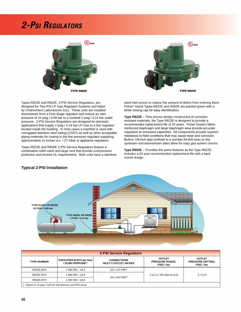
Types R622E and R652E, 2-PSI Service Regulators, are designed for Two-PSI LP-Gas Regulator Systems and listed by Underwriters Laboratories (UL). These units are installed downstream from a First-Stage regulator and reduce an inlet pressure of 10 psig / 0,69 bar to a nominal 2 psig / 0,14 bar outlet pressure. 2-PSI Service Regulators are designed for domestic applications that supply 2 psig / 0,14 bar LP-Gas to a line regulator located inside the building. In most cases a manifold is used with corrugated stainless steel tubing (CSST) as well as other acceptable piping materials for routing to the line pressure regulator supplying approximately 11-inches w.c. / 27 mbar to appliance regulators.
Types R622E and R652E 2-PSI Service Regulators feature a combination relief valve and large vent that provide overpressure protection and exceed UL requirements. Both units have a stainless
steel inlet screen to reduce the amount of debris from entering them. Fisher® brand Types R622E and R652E are painted green with a white closing cap for easy identifi cation.
Type R622E – Time proven design constructed of corrosion resistant materials, the Type R622E is designed to provide a recommended replacement life of 20 years. Fisher brand’s fabric-reinforced diaphragm and large diaphragm area provide accurate regulation at increased capacities. All components provide superior resistance to fi eld conditions that may cause wear and corrosion. Built-in 1/8-inch taps (orifi ced to a number 54-drill size) on the upstream and downstream sides allow for easy gas system checks.
Type R652E – Provides the same features as the Type R622E, includes a 20 year recommended replacement life with a back mount design.
Typical 2-PSI Installation
2-PSI REGULATORS
TYPE R652E TYPE R622E
2-PSI Service Regulators
TYPE NUMBER CAPACITIES IN BTU per hour / SCMH PROPANE(1)
CONNECTIONSINLET X OUTLET, INCHES
OUTLETPRESSURE RANGE,
PSIG / bar
OUTLETPRESSURE SETTING,
PSIG / bar
R622E-BCH 1 460 000 / 16,4 1/2 x 1/2 FNPT
1 to 2.2 / 69 mbar to 0,15 2 / 0,14R622E-DCH 1 680 000 / 18,93/4 x 3/4 FNPT
R652E-DFH 1 500 000 / 16,9
1. Based on 10 psig / 0,69 bar inlet pressure and 20% droop.
TYPE R652E TYPE R622E
TYPE R122H OR R622H
TYPE R622E OR R652E
10 PSIG / 0,69 bar
2 PSIG / 0,14 bar

27
Integral Two-Stage regulators combine a First-Stage regulator and a Second-Stage regulator into one compact unit. Recommended for installations where piping distance is short, integral Two-Stage regulators provide all of the advantages of Two-Stage regulation (refer to page 23). Fisher® brand integral Two-Stage regulators are color coded gray for easy identifi cation. Vents are screened with standard Second-Stage vent orientation over the outlet.The Types R632 and R232 fi rst-stage screened vent is threaded to accept a 1/4-inch OD copper tube inverted fl are with a 7/16-24 UN thread.
Type R632 – is an Underwriters Laboratories (UL) listed regulator with a capacity of up to 850 000 BTU per hour / 9,6 SCMH, recommended for on-site cylinder installations, mobile homes and domestic installations, where separation of the First and Second-Stage is not cost effective. This unit offers a POL inlet connection for the easy drop-in replacement of Single-Stage regulators.
Type R632’s high capacity relief valve and large 3/4-inch screened vent limit downstream pressure to less than 2 psig / 0,14 bar in an overpressure situation as required by NFPA 58. Type R632 is adjustable from 9 to 13-inches w.c. / 22 to 32 mbar, with a factory setpoint of 11-inches w.c. / 27 mbar. The Type R632 features include the 20 year recommended replacement life.
Type R632 has 1/8-inch NPT built-in gauge taps, orifi ced to a No. 54 drill size, on the upstream and downstream sides. These taps provide easy access for testing the proper operation of the First and Second-Stage while the system is pressurized. This regulator also features a large 3/4-inch drip-lip vent to reduce the
chance of blockage by freezing rain or sleet when properly installed with the vent pointing down.
Type R232 – Designed for installations with small capacity loads up to 450 000 BTU per hour / 5,1 SCMH. With an overall length of 6.5 or 7-inches / 165 or 178 mm for NPT or FPOL connections respectively, this compact unit fi ts easily into confi ned spaces and is ideal for ASME tanks used on small domestic loads. Intermediate and outlet gauge taps facilitate easy system testing. A 3/8-inch NPT vent allows easy installation of vent piping. Use of a valve stem and lever provide stable regulation and excellent durability. A large fabric-reinforced diaphragm provides accurate regulation. The large orifi ce assists in minimizing freeze problems. Stainless steel internal and corrosion resistant coatings provide excellent corrosion resistance. The Type R232 also has the design that provides a recommended replacement life of 20 years.
Twin Cylinder Installations – The Type R232 can also be used on twin cylinder hook-ups found on travel trailers and stationary applications. These units offer a drip-lip vent style for installations without a vent protector. Proper installation requires the vent to be pointed down in a vertical position. Additional protection may be required if road splatter is a problem.
A Type P414 manifold can be installed in the regulator’s inlet. The Type P414 is a tee check style with a check disc that blocks the fl ow to the reserve cylinder. The disc moves to either one side of the manifold or the other depending upon which cylinder is to supply gas.
INTEGRAL TWO-STAGE REGULATORS
TYPE R632 TYPE R232
Integral Two-Stage Regulators
TYPE NUMBERCAPACITIES IN
BTU per hour / SCMH PROPANE(1)
INLET CONNECTION, INCHES
OUTLET CONNECTION, INCHES
OUTLETADJUSTMENT RANGE,
INCHES W.C. / mbar
OUTLETPRESSURE SETTING,INCHES W.C. / mbar
R232-BBF
450 000 / 5,11/4 FNPT
1/2 FNPT 9.5 to 13/ 24 to 32
11 / 27
R232-BBFXA(2)
R232-HBFFPOL
R232-HBFXA(2)
R632-BCF750 000 / 8,4
1/4 FNPT1/2 FNPT
9 to 13/ 22 to 32
R632-BCFXA(2)
R632-CFF850 000 / 9,6 3/4 FNPT
R632-CFFXA(2)
R632-HCF750 000 / 8,4
FPOL1/2 FNPT
R632-HCFXA(2)
R632-JFF850 000 / 9,6 3/4 FNPT
R632-JFFXA(2)
1. Based on 30 psig / 2,1 bar inlet pressure and 2-inches w.c. / 5 mbar droop.2. First and Second-Stage spring case vents opposite gauge taps.

28
Fisher® brand automatic changeover regulators change from the supply cylinder (when gas is exhausted) to the reserve cylinder automatically.
Type R962 – Type R110 automatic changeover manifold serves as the First-Stage portion of the assembly, connecting to a Type R622 Second-Stage regulator which reduces the pressure to 11-inches w.c. / 27 mbar for appliances.
Type R962 eliminates gas outage problems by switching from the nearly empty cylinder to the reserve cylinder automatically. Gas is withdrawn from the supply cylinder until pressure reaches about 7 psig / 0,48 bar. The changeover manifold then switches to the full cylinder. A red warning fl ag appears in the built-in indicator to show the changeover has taken place. Additional protection for the vent may be required for Type R962 to prevent wheel spray from blocking the vent with mud on mobile installations. Type R962 does not comply with NFPA 58 or UL 144.
TYPE R962-31
Commercial Automatic Changeover RegulatorsDesigned for large capacity multi-cylinder or tank installations, these regulators are used on applications such as bakeries, motels, restaurants, and grain dryers. The manifold portion of the assembly consists of two 64 Series regulators and a direct mounted 803 Series indicator.
Type 64SR-122 – For high pressure (pounds to pounds) service with the outlet pressure supplied by a Type 64SR that has internal relief protection.
AUTOMATIC CHANGEOVER REGULATORS
Automatic Changeover RegulatorsTYPE NUMBER(1)
HIGH CAPACITY RELIEFCAPACITIES IN BTU per hour /
SCMH PROPANE(1)INLET
CONNECTION, INCHESOUTLET
CONNECTION, INCHESVENT
SIZE, INCHES
R962-31(Types R110 and R622) 600 000 / 6,7 1/4 Inverted Flare 1/2 FNPT 3/4 FNPT
1. Capacity based on 30 psig / 2,1 bar inlet pressure, 11-inches w.c. / 27 mbar outlet pressure setting, and 2-inches w.c. / 5 mbar droop.
TYPE 64SR-122
Commercial Automatic Changeover Regulators
TYPE NUMBERCAPACITIES IN
BTU per hour / SCMH PROPANE(1)
INLET CONNECTION, INCHES
OUTLET CONNECTION, INCHES
OUTLET PRESSURE SETTING, PSIG / bar
OUTLET ADJUSTMENT RANGE, PSIG / bar
64SR-122 1 210 000 / 13,6 1/2 FNPT 1/2 FNPT 10 / 0,69 5 to 20 / 0,34 to 1,4

29
AUTOMATIC CHANGEOVER REGULATORS
Changeover Manifold AssembliesType R110-21 – This manifold supplies an outlet pressure of approximately 15 psig / 1,0 bar from the supply cylinder and 7 psig / 0,48 bar from the reserve cylinder. A built-in indicator gives indication of when the changeover has taken place. This manifold changeover regulator can connect to a Second-Stage regulator but does not comply with NFPA 58 or UL 144.
Type R130-21 – Composed of two Type 67C regulators and a special 0 to 60 psig / 0 to 4,1 bar pressure gauge, the Type R130 delivers a 45 psig / 3,1 bar outlet pressure on supply and 30 psig / 2,1 bar on reserve. The gauge, which serves as the changeover indicator, is painted red from 0 to 35 psig / 0 to 2,4 bar. When the dial reads in the 0 to 35 psig / 0 to 2,4 bar range, it indicates that the manifold has switched from the supply to the reserve cylinder.
Type 749B-21 – Large capacity changeover manifold for commercial and industrial applications. It consists of two 64 Series regulators and a 803 Series direct indicator. The assembly is used primarily in conjunction with either an Type HSRL or a Type 64SR regulator. The standard outlet setting is 15 psig / 1,0 bar from the supply and 5 psig / 0,34 bar from the reserve.
Note: These units are intended for use with Second-Stage regulators and/or separate relief devices which provide overpressure protection required by NFPA 58. Capacity of all these changeover manifolds is dependent on the size of the Second-Stage regulator with which they are used. If the manifolds are used as a Final-Stage (pounds to pounds), a relief valve is required in the downstream system.
TYPE R110-21
TYPE R130-21
TYPE 749B-21
Changeover Manifold Regulators
TYPE NUMBERCAPACITIES IN
BTU per hour / SCMH PROPANE(1)
INLETCONNECTION, INCHES
OUTLETCONNECTION, INCHES
OUTLET PRESSURE SETTING
Supply Setting,psig / bar
Reserve Setting,psig / bar
R110-21 500 000 / 5,6 1/4 Inverted Flare 1/4 FNPT 15 / 1,0 7 / 0,48
R130-21 1 475 000 / 16,6 1/4 FNPT 1/4 FNPT 45 / 3,1 30 / 2,1
749B-21 1 500 000 / 16,9 1/2 FNPT 1/2 FNPT 15 / 1,0 5 / 0,34
1. Based on 100 psig / 6,9 bar inlet, reserve setting.
TYPE R110-21
TYPE R130-21
TYPE 749B-21
Remote Indicator
803 Series – give remote visual indication that the supply cylinder is empty and that the regulator is withdrawing gas from the reserve cylinder. The indicator has 360° visibility and is weatherproof.
Type 803-21 – Indicator only
TYPE 803-21

30
67C SeriesSuitable for liquid or vapor service, the 67C Series high pressure (pounds to pounds) regulators are used on a variety of applications. All types within the series have a 1/4-inch FNPT side outlet in which a pressure gauge (J500 Series) can be installed. The compact size of the 67C Series regulators make them particularly useful on installations where space is limited.
The regulator design utilizes precise guiding of the valve plug to provide close regulation and high performance.
Type 67CW – Standard regulator with wrench adjustment.
Type 67CH – Standard regulator with handwheel adjustment.
Type 67CD – With dial calibration accuracy nearly equivalent to that of a commercial pressure gauge, the Type 67CD eliminates the need for a pressure gauge on portable applications.
Outlet pressure is calibrated on the spring case allowing visual adjustment of the outlet pressure without having to use a pressure gauge. The unit is ideal for service where gauge breakage is a problem.
Type 67CN – Extremely compact unit with a fi xed (non-adjustable) outlet setting and a tamper resistant spring case. Three different setpoints are available: 10, 15, and 20 psig / 0,69; 1,0; and 1,4 bar.
Note: 67C Series regulators do not have an internal reliefand should be installed with additional/external overpressure protection. These units should not be installed in fi xed piping serving 14-inches w.c. / 35 mbar appliance systems. Please consult with your LP-Gas Equipment Distributor for more information.
TYPE 67CW TYPE 67CH TYPE 67CD TYPE 67CN
High Pressure Regulators
TYPE NUMBER DESCRIPTION CAPACITIES IN BTU per hour / SCMH PROPANE(1)
OUTLET PRESSURE SETTING, psig / bar
OUTLET ADJUSTMENT RANGE, psig / bar
INLET AND OUTLET CONNECTIONS, INCHES
67CW-683
Basic Regulator (Wrench Adjustment)
675 000 / 7,6 15 / 1,0 3 to 20 / 0,21 to 1,4
1/4 FNPT
67CW-684 750 000 / 8,4 20 / 1,4 3 to 35 / 0,21 to 2,4
67CW-685 1 200 000 / 13,5 40 / 2,8 30 to 60 / 2,1 to 4,1
67CW-701 1 000 000 / 11,3 50 / 3,4 50 to 120 / 3,4 to 8,3
67CH-751
Basic Regulator (Handwheel Adjustment)
675 000 / 7,6 15 / 1,0 3 to 20 / 0,21 to 1,4
67CH-743 750 000 / 8,4 20 / 1,4 3 to 35 / 0,21 to 2,4
67CH-742 1 200 000 / 13,5 40 / 2,8 30 to 60 / 2,1 to 4,1
67CH-741 1 000 000 / 11,3 50 / 3,4 50 to 120 / 3,4 to 8,3
67CH-745Basic Regulator
(Handwheel Adjustment) with Type M318 installed
750 000 / 8,4 20 / 1,4 3 to 35 / 0,21 to 2,4
67CD-100
Dial Cap Adjustment
675 000 / 7,6 15 / 1,0 5 to 20 / 0,34 to 1,4
67CD-102 1 200 000 / 13,5 40 / 2,8 20 to 50 / 1,4 to 3,4
67CD-103 1 000 000 / 11,3 50 / 3,4 40 to 100 / 2,8 to 6,9
67CN-106
Non-Adjustable
400 000 / 4,5 10 / 0,69 Non-Adjustable
67CN-104 600 000 / 6,7 15 / 1,0 Non-Adjustable
67CN-105 750 000 / 8,4 20 / 1,4 Non-Adjustable
1. Based on inlet pressure 20 psig / 1,4 bar greater than outlet with 20% droop; Liquid capacity = 3 to 5 GPH / 11,4 to 18,9 l/hr .
COMMERCIAL/INDUSTRIAL HIGH PRESSURE REGULATORS

31
64 SeriesHigh pressure (pounds to pounds) regulators usually reduce tank pressure to an intermediate pressure for use by another regulator. They may be used as high pressure regulators on distribution systems when used in conjunction with a First-Stage downstream regulator. The Type 64SR may be used for First-Stage when set at 10 psig / 0,69 bar. They are also used for Final-Stage service on high pressure burners in crop dryers and tobacco curers, as well as other medium sized commercial/industrial applications.
The 1/4-inch FNPT side outlet, which is normally plugged, provides an opening for an outlet pressure gauge. Standard 64’s Series are capable of handling liquid or vapor at temperatures under 150°F/ 66°C. A cover or auxiliary vent assembly should be used to protect the 1/4-inch FNPT regulator vent opening on outdoor installations.
64 Series – is an adjustable high pressure regulator with a wide range of available outlet pressure ranges. It does not contain a relief valve. It should always be used in conjunction with a downstream
regulator and/or separate relief devices in compliance with NFPA 58 overpressure protection requirements.
Type 64SR – is a high pressure regulator, which has an internal relief valve. As such it may be used as a Final-Stage regulator on high pressure systems. It may also be used as a First-Stage regulator when set at 10 psig / 0,69 bar or less.
Note: 64 Series regulators do not have an internal reliefand should be installed with additional/external overpressure protection. These units should not be installed in fi xed piping serving 14-inches w.c. / 35 mbar appliance systems. Please consult with your LP-Gas Equipment Distributor for more information.
Note: If the installation location makes the ignition of vented gas a possibility, then a vent line should be installed from the Type 64SR vent to a safe location.
High Pressure RegulatorsTYPE NUMBER DESCRIPTION CAPACITIES IN BTU per hour
/ SCMH PROPANE(1)OUTLET PRESSURE SETTING, psig / bar
OUTLET ADJUSTMENT RANGE, psig / bar
INLET AND OUTLET CONNECTIONS, INCHES
64-33
Basic Regulator
2 625 000 / 29,6 10 / 0,69 3 to 15 / 0,21 to 1,0
1/2 FNPT
64-35 3 600 000 / 40,5 20 / 1,4 5 to 35 / 0,34 to 2,4
64-36 4 150 000 / 46,7 40 / 2,8 30 to 60 / 2,1 to 4,1
64-222 5 250 000 / 59,1 50 / 3,4 35 to 100 / 2,4 to 6,9
64SR-21
With InternalRelief Valve
2 625 000 / 29,6 10 / 0,69 3 to 15 / 0,21 to 1,0
64SR-22 3 000 000 / 33,8 15 / 1,0 5 to 20 / 0,34 to 1,4
64SR-23 3 600 000 / 40,5 20 / 1,4 5 to 35 / 0,34 to 2,4
1. Based on inlet pressure 20 psig / 1,4 bar greater than outlet with 20% droop; Liquid capacity = 160 GPH / 606 l/hr.
64 SERIES
COMMERCIAL/INDUSTRIAL HIGH PRESSURE REGULATORS

32
For Commercial and Industrial high-pressure applications like factories, offi ce building, restaurants, etc., Regulator Technologies has a wide variety of products. For ease of reference, only the most popular commercial and industrial regulators are shown in these pages. Other orifi ce sizes, body sizes, and outlet pressure ranges are available. The higher capacities on commercial and industrial installations usually require a Two-Stage regulator system.
Note: Because of various spring ranges and orifi ce sizes, all commercial and industrial regulators should be individually sized for the particular installation. Consult specifi c product bulletins for maximum pressure ratings. Contact your local LP-Gas Equipment Distributor for assistance.
Types 627 and 630 – Large capacity direct-operated high pressure regulators designed for loads up to 10 700 000 and 14 000 000 BTU per hour / 120 and 157 SCMH, respectively. The Types 627 and 630 are normally used in conjunction with Type CS400 units, however, they can also be used on Final-Stage (pounds to pounds) service. Additional overpressure protection is recommended to prevent excessive build-up in the downstream line. The diaphragm case and body of the Type 627 can be rotated in four positions to allow easy installation. Additional confi gurations of the Type 627 with internal relief and control line connections for monitor systems are available. For both theTypes 630 and 627, additional pressure ranges and orifi ce sizes are available.
Note: Types 627 and 630 regulators do not have an internal relief and should be installed with additional/external overpressure protection. These units should not be installed as part of a 2-stage system in fi xed piping serving 14-inches w.c. / 35 mbar appliance systems unless additional overpressure protection is installed that will make the system compliant with NFPA 58 requirements for a 2-stage system. Please consult with your LP-Gas Equipment Distributor for more information.
Flanged Bodies – The Type 630 and Type 627 are available with fl anged bodies. Flanges are available for 2-inch CL300 FF.
Overpressure Protection – The Type 627 is also available in monitor confi gurations. Note that the Type 627 monitor regulators have unique type numbers. For more information on monitor overpressure protection, see Page 42.
Fluorocarbon Trim – The Type 627 is available with Fluorocarbon (FKM) Trim for high temperature applications such as vaporizors. Part numbers are listed below with a ‘V’ suffi x.
Type 1301F – The proven reliability and accurate regulation of the Type 1301F regulator makes it ideal for numerous high-pressure drop applications. This multi-purpose regulator can be used as pilot supply or pressure-loading regulators where high-pressure operating medium must be reduced for use by gas regulator pilots or pressure-loaded regulators.
TYPE 630TYPE 627
COMMERCIAL/INDUSTRIAL DIRECT-OPERATED HIGH PRESSURE REGULATORS

33
High Pressure Commercial/Industrial RegulatorsTYPE
NUMBER
CAPACITIES IN BTU per hour / SCMH
PROPANE
ORIFICE SIZE,INCHES / mm
INLET AND OUTLETCONNECTIONS
OUTLET PRESSURERANGE, psig / bar
OUTLET PRESSURESETTING, psig / bar
MAXIMUM OPERATING INLETPRESSURE, psig / bar
627R-113(5) 6 080 000 / 68,4
3/8 / 9,5
3/4-inch FNPT 5 to 20 / 0,34 to 1,4 10 / 0,69
200 / 13,8
627-5810(3) 6 080 000 / 68,4 250 / 17,2
627-5810V 6 080 000 / 68,4 250 / 17,2
627M-421(4) 10 755 000 / 121
1/2 / 13
250 / 17,2
627R-117(5) 10 755 000 / 121 200 / 13,8
627-6210(3) 10 755 000 / 121 250 / 17,2
627-6210V 10 755 000 / 121 250 / 17,2
627R-193(5) 7 434 000 / 83,5
3/8 / 9,5
1-inch FNPT
5 to 20 / 0,34 to 1,4 10 / 0,69 200 / 13,8
627-117 14 632 000 / 164
15 to 40 / 1,0 to 2,8 40 / 2,8
250 / 17,2
627-493 14 632 000 / 164 250 / 17,2
627R-194(5) 14 632 000 / 164 200 / 13,8
627-496 10 773 000 / 121
1/2 / 13
5 to 20 / 0,34 to 1,4 10 / 0,69
250 / 17,2
627-576 10 773 000 / 121 250 / 17,2
627M-471(4) 10 773 000 / 121 250 / 17,2
627R-197(5) 10 773 000 / 121 200 / 13,8
627-7710(3) 10 773 000 / 121 250 / 17,2
627-7710V 10 773 000 / 121 250 / 17,2
627-497 14 837 000 / 16715 to 40 / 1,0 to 2,8 40 / 2,8
250 / 17,2
627R-198(5) 14 837 000 / 167 200 / 13,8
627-577 20 948 000 / 2351/2 / 13 2-inch FNPT 15 to 40 / 1,0 to 2,8 40 / 2,8
250 / 17,2
627M-268(4) 20 948 000 / 235 250 / 17,2
630-104/78 14 000 000 / 158 1/2 / 13 2-inch FNPT 8 to 20 / 0,55 to 1,4 10 / 0,69 250 / 17,2
630-104/78F 14 000 000 / 158 1/2 / 13 2-inch / DN 50 CL300 FF 8 to 20 / 0,55 to 1,4 10 / 0,69 250 / 17,2
1301F-1 3 863 000 / 43,5(2) 5/64 / 2,0 1/4-inch FNPT 10 to 75 / 0,69 to 5,2 75 / 5,2 6000 / 414
1. For Types 627 and 630, capacity based on inlet pressure 20 psig / 1,4 bar greater than outlet pressure, Internal registration, and 20% droop.2. Capacity based on 2000 psig / 138 bar inlet pressure and 10% droop.3. UL listed construction.4. For Monitor Applications. Standard with blocked throat and external sensing. 5. “R” denotes token relief. Check with your LP-Gas Equipment Distributor on relief capacities. NOTE: Additional spring ranges and body styles are available. Ask your LP-Gas Equipment Distributor for additional configurations and for more information.
COMMERCIAL/INDUSTRIAL DIRECT-OPERATED HIGH PRESSURE REGULATORS

34
Pilot-Operated High Pressure Commercial/Industrial RegulatorsTYPE
NUMBER
CAPACITIES IN BTU per hour / SCMH
PROPANE(1)
ORIFICE SIZE,INCHES / mm
INLET AND OUTLET CONNECTIONS
OUTLET PRESSURE RANGE, psig / bar
OUTLET PRESSURE SETTING, psig / bar
MAXIMUM OPERATING INLET PRESSURE,
psig / bar99-510P
29 400 000 / 331
7/8 / 22
2-inch FNPT 7-inches w.c. to 2 / 17 mbar to 0,14 1 / 69 mbar
250 / 17,2
99F-510P 2-inch / DN 50 CL300 FF99-511P
33 206 000 / 3742-inch FNPT
1 to 5 / 69 mbar to 0,34 5 / 0,3499F-511P 2-inch / DN 50 CL300 FF99-513P
36 368 000 / 4092-inch FNPT
2 to 10 / 0,14 to 0,69 10 / 0,6999F-513P 2-inch / DN 50 CL300 FF99-512P
37 950 000 / 4272-inch FNPT
5 to 15 / 0,34 to 1,0 15 / 1,099F-512P 2-inch / DN 50 CL300 FF99-515P
41 112 000 / 4632-inch FNPT
10 to 20 / 0,69 to 1,4 20 / 1,499F-515P 2-inch / DN 50 CL300 FF99-903P
44 275 000 / 4982-inch FNPT
10 to 65 / 0,69 to 4,5 30 / 2,199F-903P 2-inch / DN 50 CL300 FF99-502PH
50 600 000 / 570
1-1/8 / 29
2-inch FNPT1 to 5 / 69 mbar to 0,34 5 / 0,34
300 / 20,7
99F-502PH 2-inch / DN 50 CL300 FF99-503PH 61 668 000 / 694 2-inch FNPT
2 to 10 / 0,14 to 0,69 10 / 0,6999F-503PH 61 668 000 / 694 2-inch / DN 50 CL300 FF99-504PH 63 250 000 / 712 2-inch FNPT
5 to 15 / 0,34 to 1,0 15 / 1,099F-504PH 63 250 000 / 712 2-inch / DN 50 CL300 FF99-505PH 67 993 000 / 765 2-inch FNPT
10 to 20 / 0,69 to 1,4 20 / 1,499F-505PH 67 993 000 / 765 2-inch / DN 50 CL300 FF99-901PH 74 318 000 / 837 2-inch FNPT
10 to 65 / 0,69 to 4,5 30 / 2,199F-901PH 74 318 000 / 837 2-inch / DN 50 CL300 FF
1. Capacity based on inlet pressure 20 psig / 1,4 bar greater than outlet pressure, external registration, and 20% droop. NOTE: Additional spring ranges and body styles are available. Ask your LP-Gas Equipment distributor for more information.
For Commercial and Industrial high-pressure applications, such as distributed community systems, factories, offi ce buildings, restaurants, Regulator Technologies has a wide variety of products and solutions. For ease of reference, only the most popular commercial and industrial regulators are shown on these pages. Other orifi ce sizes, body sizes, and outlet pressure ranges are available. The higher capacities on commercial and industrial installations usually require a Two-stage regulator system.
Note: Because of various spring ranges and orifi ce sizes, all commercial and industrial regulators should be individually sized for the particular installation. Consult specifi c product bulletins for maximum pressure ratings. Contact your local LP-Gas Equipment Distributor for assistance.
Type 99 – Pilot-operated unit keeps outlet pressure constant despite varying fl ow rates and inlet pressures. Designed to handle loads up to 74 318 000 BTU per hour / 837 SCMH, the Type 99 is ideal for multiple customer installations. The unique pilot design, with fast opening and closing operation, makes the Type 99 ideal for large
industrial boiler applications. The Type 99 can be used for low or high pressure applications. A downstream control line is required. Additional overpressure protection is recommended to prevent excessive buildup in the downstream line.
Note: Type 99 regulators do not have an internal relief and should be installed with additional/external overpressure protection. These units should not be installed as part of a 2-stage system in fi xed piping serving 14-inches w.c. / 35 mbar appliance systems unless additional overpressure protection is installed that will make the system compliant with NFPA 58 requirements for a 2-stage system. Please consult with your LP-Gas Equipment Distributor for more information.
Flanged Bodies - 99F Series is equipped with 2-inch CL300 fl anged bodies.
Overpressure Protection - The Type 99 is also available in monitor confi gurations. Note that the Type 99 monitor regulators have unique type numbers. For more information on monitor overpressure protection, see page 41.
TYPE 99
COMMERCIAL/INDUSTRIAL PILOT-OPERATED HIGH PRESSURE REGULATORS COMMERCIAL/INDUSTRIAL PILOT-OPERATED HIGH PRESSURE REGULATORS

35
Pilot-Operated High Pressure Commercial/Industrial RegulatorsTYPE
NUMBER
CAPACITIES IN BTU per hour / SCMH
PROPANE
ORIFICE SIZE,INCHES / mm
INLET AND OUTLET CONNECTIONS
OUTLET PRESSURE RANGE, psig / bar
OUTLET PRESSURE SETTING, psig / bar
MAXIMUM OPERATING INLET PRESSURE,
psig / bar
1098-L21 170 500 000 / 1915(1)
2-3/8 / 60
2-inch FNPT
2 to 10 / 0,14 to 6,9 10 / 6,9
400 / 27,6
1098-L22 215 300 000 / 2419(2) 3 to 40 / 0,21 to 2,7 20 / 1,4
1098-L23 322 300 000 / 3621(3) 35 to 75 / 2,4 to 5,2 50 / 3,4
1098-F21 170 500 000 / 1915(1)
2-inch / DN 50 CL300 FF
2 to 10 / 0,14 to 6,9 10 / 6,9
1098-F22 215 300 000 / 2419(2) 3 to 40 / 0,21 to 2,7 20 / 1,4
1098-F23 322 300 000 / 3621(3) 35 to 75 / 2,4 to 5,2 50 / 3,4
1098-F31 356 300 000 / 4003(1)
3-3/8 / 86 3-inch / DN 80 CL300 FF
2 to 10 / 0,14 to 6,9 10 / 6,9
1098-F32 447 400 000 / 5026(2) 3 to 40 / 0,21 to 2,7 20 / 1,4
1098-F33 669 500 000 / 7521(3) 35 to 75 / 2,4 to 5,2 50 / 3,4
1098-F41 551 300 000 / 6193(4)
4-3/8 / 111 4-inch / DN 100 CL300 FF
2 to 10 / 0,14 to 6,9 10 / 6,9
1098-F42 693 500 000 / 7791(4) 3 to 40 / 0,21 to 2,7 20 / 1,4
1098-F43 1 035 500 000 / 11 633(3) 35 to 75 / 2,4 to 5,2 50 / 3,4
NOTE: Additional spring ranges and body styles are available. Ask your LP-Gas Equipment Distributor for more information. 1. Capacity based on 30 psig / 2,1 bar inlet pressure and 15 psig / 1,0 bar setpoint. 2. Capacity based on 40 psig / 2,8 bar inlet pressure and 20 psig / 1,4 bar setpoint. 3. Capacity based on 75 psig / 5,2 bar inlet pressure and 50 psig / 3,4 bar setpoint. 4. Capacity based on 25 psig / 1,7 bar inlet pressure greater than outlet pressure setting.
TYPE 1098-EGR
Type 1098 - The Type 1098-EGR regulator provides large capacities for use in large commercial applications and large distributed community systems. Designed to handle loads from 170 000 000 BTU / 1910 SCM (2-inch size) to in excess of 1 000 000 000 BTU / 11 234 SCM (4-inch size) and rated to 75 psig / 5,2 bar for Maximum Outlet Pressure, the Type 1098H is a regulator unmatched in performance in the LP-Gas Industry. The Type 1098’s pilot-operated two-path system is designed to quickly respond to sudden changes in the downstream demand, making this regulator ideal for fuel gas supply to industrial boilers, furnaces, ovens, and mixers.
Type 1098H - The Type 1098H-EGR regulator also provides large capacities used in systems similar to Type 1098. The Type 1098H uses a special cast iron actuator assembly that increases the Maximum Downstream Pressure rating of the standard Type 1098 up to 300 psig / 20,7 bar, offering an even greater level of protection with outlet pressure settings up to 125 psig / 8,6 bar.
Flanged Bodies - The Types 1098 and 1098H are available with fl anged bodies. Flanges are available in 2, 3, and 4-inch body sizes and CL300 FF end connection.
Note: Type 1098 regulators do not have an internal relief and should be installed with additional/external overpressure protection. These units should not be installed as part of a 2-stage system in fi xed piping serving 14-inches w.c. / 35 mbar appliance systems unless additional overpressure protection is installed that will make the system compliant with NFPA 58 requirements for a 2-stage system. Please consult with your LP-Gas Equipment Distributor for more information.
Overpressure Protection - The Type 1098H is also available in monitor confi gurations. Note that the Type 1098H regulators may be used either as the worker or monitor regulator. For more information on monitor overpressure protection, see page 41.
The Type 1098 regulator is a highly advanced regulator with many confi gurations for various applications. Always consultRegulator Technologies to discuss your application prior to placing your order.
COMMERCIAL/INDUSTRIAL PILOT-OPERATED HIGH PRESSURE REGULATORS

36
TYPE CS400 TYPE CS800 NEWTYPE CS200
COMMERCIAL LOW PRESSURE REGULATORS
Regulator Technologies has a wide range of low-pressure regulators to meet almost any commercial or industrial application. For ease of reference, only the most popular commercial and industrial regulators are shown on this page. Other orifi ce sizes, body sizes, and outlet pressure ranges are available. See the product guides on pages 37 and 39.
Note: Because of various spring ranges and orifi ce sizes, all commercial and industrial regulators should be individually sized for the particular installation. Consult specifi c product bulletins for maximum pressures ratings. Contact your local LP-Gas Equipment Distributor for assistance.
Type CS400 – The Type CS400 is a medium capacity low pressure, direct-operated regulator designed for loads up to 7 800 000 BTU per hour / 88 SCMH, ideal for installations at schools, bakeries, and many other commercial/industrial applications. Available in 1-1/4, 1-1/2, and 2-inch body sizes with spring ranges from 4.5-inches w.c. to 5.5 psig / 11 mbar to 0,38 bar.
Type CS200 – The Type CS200 is a medium capacity low pressure, direct-operated regulator designed for loads up to 3 800 000 BTU per hour / 44 SCMH, ideal for installations on smaller
Low Pressure Commercial Regulators
TYPE NUMBERCAPACITIES IN
BTU per hour / SCMH PROPANE(1)
ORIFICE SIZE,INCHES / mm
INLET AND OUTLET CONNECTIONS,
INCHES
OUTLETPRESSURE RANGE
OUTLETPRESSURE
SETTING
MAXIMUM OPERATING INLET PRESSURE,
psig / barCS200IR-6EC1 2 500 000 / 28
1/2 / 12,73/4 FNPT
10 to 14-inches w.c. / 25 to 35 mbar11-inches w.c.
/ 27 mbar
40 / 2,8CS200IR-6EC3 3 800 000 / 43 1 FNPTCS200IR-6EC6 3 900 000 / 44 1-1/4 FNPTCS400IR-8EC6 6 800 000 / 76
3/4 / 19,11-1/4 FNPT
20 / 1,4CS400IR-8EC7 7 600 000 / 85 1-1/2 FNPTCS400IR-8EC8 7 600 000 / 85 2 FNPT CS800IR-8CC7 10 460 000 / 118
1 / 25,41-1/2 FNPT
8 to 12-inches w.c. / 20 to 30 mbar 30 / 2,1CS800IR-8CC8 21 809 000 / 245 2 FNPTCS200IR-6HC1 3 760 000 / 42
1/2 / 12,73/4 FNPT
1 to 2 psig / 0,06 to 0,14 bar 2 psig / 0,14 bar
40 / 2,8CS200IR-6HC3 4 780 000 / 54 1 FNPTCS200IR-6HC6 5 327 000 / 60 1-1/4 FNPTCS400IR-8HC6 9 715 000 / 109
3/4 / 19,11-1/4 FNPT
20 / 1,4CS400IR-8HC7 10 500 000 / 118 1-1/4 FNPTCS400IR-8HC8 8 775 000 / 99 2 FNPTCS820IR-8FC7 15 011 000 / 169
1 / 25,41-1/2 FNPT
1 to 2.5 psig / 0,06 to 0,17 bar 30 / 2,1CS820IR-8FC8 21 436 000 / 241 2 FNPTCS400IR-8IC6 7 365 000 / 83
3/4 / 19,11-1/4 FNPT
2 to 5.5 psig / 0,14 to 0,38 bar5 psig / 0,35 bar
20 / 1,4CS400IR-8IC7 6 895 000 / 77 1-1/2 FNPTCS400IR-8IC8 7 365 000 / 83(2) 2 FNPTCS820IR-8HC7 15 262 000 / 171
1 / 25,41-1/2 FNPT
2.5 to 5.5 psig / 0,17 to 0,38 bar 30 / 2,1CS820IR-8HC8 16 532 000 / 186 2 FNPT
1. Capacities are based on 10 psig / 0,69 bar and 2-inches w.c. / 5 mbar droop. 2. Capacities are based on 10 psig / 0,69 bar and 20% droop. NOTE: Additional combinations of body sizes, spring ranges, and orifi ce sizes are available. See guides on Page 37. Consult your LP-Gas Equipment distributor for more information.
commercial/industrial applications. Available in 3/4, 1, and 1-1/4-inch body sizes with spring ranges from 3.5-inches w.c. to 2 psig / 9 mbar to 0,14 bar.
Flanged Bodies – The Types CS400 and CS800 are available with a fl anged body. Flanges are available in 2-inch / DN 50 body size and CL125 FF end connection.
Type CS800 – The Type CS800 is a direct-operated, spring-loaded regulator which has been engineered for low pressure commercial service applications. This regulator can accommodate up to 21 600 000 BTU per hour / 243 SCMH of fl ow capacity and is available in 1-1/2 and 2-inch body sizes with 8-inches w.c. to 5.5 psig / 20 mbar to 0,38 bar pressure ranges.
Note: Types CS200, CS400, and CS800 regulators should be installed with additional/external overpressure protection. These units when installed as part of a 2-stage system in fi xed piping serving 14-inches w.c. / 35 mbar appliance systems require additional overpressure protection to make the system compliant with NFPA 58 requirements for a 2-stage system. Please consult with your LP-Gas Equipment Distributor for more information.

37
Type CS200 Selection Guide
BASE SENSING RELIEF ORIFICE REGULATOR SETPOINTS BODY OPTION
CODE DESCRIPTION CODE DESCRIPTION CODE DESCRIPTION CODE SIZEInch / mm CODE Inches w.c. / mbar CODE DESCRIPTION
CS200 Basic I Internal N None 1 1/8 / 3,2 A 3.5 to 5 / 9 to 12 C1 3/4-inch FNPT,Cast Iron
R Internal 2 3/16 / 4,8 B 4.5 to 6.5 / 11 to 16 C3 1-inch FNPT,Cast Iron
3 1/4 / 6,4 C 6 to 8 / 15 to 20 C6 1-1/4-inch FNPT,Cast Iron
5 3/8 / 9,5 D 7.5 to 11 / 19 to 27
6 1/2 / 12,7 E 10 to 14 / 25 to 35
F 12 to 19 / 30 to 47
G 18 to 1 psig / 45 mbar to 0,06 bar
H 1 to 2 psig / 0,06 to 0,13 bar
Type CS400 Selection Guide
BASE SENSING RELIEF ORIFICE REGULATOR SETPOINTS BODY OPTION
CODE DESCRIPTION CODE DESCRIPTION CODE DESCRIPTION CODE SIZEInch / mm CODE Inches w.c. / mbar CODE DESCRIPTION
CS400 Basic I Internal N None 2 3/16 / 4,8 A 3.5 to 5 / 9 to 12 C6 1-1/4-inch FNPT, Cast Iron
E External R Internal 3 1/4 / 6,4 B 4.5 to 6.5 / 11 to 16 C7 1-1/2-inch FNPT,Cast Iron
T Token 5 3/8 / 9,5 C 6 to 8 / 15 to 20 C8 2-inch FNPT, Cast Iron
6 1/2 / 12,7 D 7.5 to 11 / 19 to 27 C92 inch / DN 50
CL150 FF, Ductile Iron
8 3/4 / 19,1 E 10 to 14 / 25 to 35
F 12 to 19 / 30 to 47
G 18 to 1 psig / 45 mbar to 0,06 bar
H 1 to 2 psig / 0,06 to 0,13 bar
I 2 to 5.5 psig / 0,14 to 0,38
Type CS800 Selection Guide
BASE SENSING RELIEF ORIFICE REGULATOR SETPOINTS BODY OPTION
CODE DESCRIPTION CODE DESCRIPTION CODE DESCRIPTION CODE SIZEInch / mm CODE Inches w.c. / mbar CODE DESCRIPTION
CS800 Basic I Internal N None 2 1/4 / 6,4 A 3.5 to 6 / 9 to 15 C6 1-1/4-inch FNPT, Gray Iron
CS820 High Outlet E External R Internal 3 3/8 / 9,5 B 5.5 to 8.5 / 11 to 16 C7 1-1/2-inch FNPT,Gray Iron
T Token 4 1/2 / 12,7 C 8 to 12 / 15 to 20 C8 2-inch FNPT, Gray Iron
Q High Capacity 6 3/4 / 19,1 D 10 to 16 / 25 to 40 C92-inch / DN 50
CL125 FFGray Iron
8 1 / 25,4 E 14 to 30 / 25 to 75 D112-inch / DN 50
CL150 FF, Ductile Iron
9 1-3/8 / 34,9 F 1 to 2.5 psig / 0,06 to 0,17 bar
G 1.5 to 3.5 / 0,10 to 0,24 bar
H 2.5 to 5.5 / 0,17 to 0,38 bar
COMMERCIAL SERVICE LOW PRESSURE REGULATORS

38
TYPE CS403
TYPE CS404
Types CS205 and CS206 Secondary Seat™ Protection
3/4-inch FNPT to 1-1/4-inch Body Sizes1.83 to 2.24 MBTU per hour / 20,6 to 25,2 SCMH
Type CS205: CS200 platform with a modifi ed orifi ce that contains a second sealing surface. Should damage occur to the primary seating surface, outlet pressure will continue to rise and prevent lockup. The additional pressure will cause the disc to push the modifi ed orifi ce into the secondary sealing surface to provide a bubble tight lockup.
Type CS206: CS205 Secondary Seat™ with a limited bleed to downstream system as an indication that the secondary seat is providing lockup. The minimal amount of gas will cause the Internal Relief to begin to discharge, allowing the odorant in the gas to be detected.
See Selection Guide on Page 39 for available options.
Type CS403 with Integral True-Monitor™ Protection
1-1/4-inch FNPT to 2-inch FNPT Body Sizes (2-inch / DN 50 CL150 Flange Available) 7.65 to 8.44 MBTU per hour / 85,9 to 94,8 SCMHInternal Registration
Type CS403: Combines operation of a conventional two-regulator wide-open monitor set into one body. During normal operation, the monitor is in a wide open state at a setpoint higher than the primary regulator. If the downstream pressure should rise due to loss of control by the primary regulator, the integral monitor will assume control and regulate the fl ow to the downstream system.
See Selection Guide on Page 39 for available options.
Type CS404 with Integral Slam shut
1-1/4-inch FNPT to 2-inch FNPT Body Sizes (2-inch / DN 50 CL150 Flange Available) 7.65 to 8.44 MBTU per hour / 85,9 to 94,8 SCMHInternal Registration
Type CS404: Integrates a fast acting shutoff device that provides overpressure shutoff (OPSO) or over/underpressure shutoff (UPSO/OPSO) protection by completely shutting off the fl ow of gas to the downstream system. The Slam Shut operates independently of the main regulator, and does not affect normal operation unless the downstream pressure fl uctuates outside of the desired ranges.
See Selection Guide on Page 39 for available options.
SETPOINT TYPE CS205 TYPE CS206
Inches w.c./ mbar Shutoff above Setpoint Downstream Pressure
Buildup7 / 17 5-inches w.c. / 12 mbar 25.1-inches w.c. / 62 mbar11 / 27 5.5-inches w.c. / 14 mbar 29.6-inches w.c. / 74 mbar14 / 35 5.8-inches w.c. / 14 mbar 1.26 psig / 0,08 bar
1 psig / 0,07 bar 7.8 inches w.c. / 19 mbar 1.90 psig / 0,13 bar2 psig / 0,14 bar 13-inches w.c. / 32 mbar 3.42 psig / 0,24 bar
PRIMARYSETPOINT
MONITORSETPOINT MONITOR SPRING RANGE
Inches w.c. mbar Inches w.c. / mbar Spring Range7 / 17 14 / 35 11 to 16-inches w.c. / 27 to 40 mbar11 / 27 21 / 52 16 to 23-inches w.c. / 40 to 57 mbar14 / 35 21 / 52 16 to 23-inches w.c. / 40 to 57 mbar
1 psig / 0,07 bar 1.5 psig / 0,10 bar 1 to 2 psig / 0,07 to 0,14 bar2 psig / 0,14 bar 2.5 psig / 0,17 bar 1.5 to 2.5 psig / 0,10 to 0,17 bar 5 psig / 0,35 bar 6 psig / 0,41 bar 4 to 7.5 psig / 0,28 to 0,52 bar
PRIMARYSETPOINT
SLAM-SHUT SETPOINT
OPSO UPSO - OPSOInches w.c. / mbar Inches w.c. / mbar Inches w.c. / mbar
7 / 17 17 / 42 - - - - 11 / 27 19 / 47 6.3 / 16 - 25 / 6214 / 35 30 / 75 8.8 / 22 - 28 / 70
1 psig / 0,07 bar 1.9 psig / 0,13 bar 16 / 40 - 1.9 psig / 0,13 bar2 psig / 0,14 bar 3.3 psig / 0,23 bar 1 psig / 0,07 bar - 3.2 psig / 0,22 bar5 psig / 0,35 bar 6.7 psig / 0,46 bar 2.9 psig / 0,20 bar - 7.5 psig / 0,52 bar
TYPE CS403
TYPE CS404
SECONDARY SEAT™ LOCKUP
PRIMARY DISC SECONDARY ORIFICE SEATING SURFACE
SECONDARY SEAT™ LOCKUP WITH BLEED
COMMERCIAL SERVICE OVERPRESSURE PROTECTION

39
COMMERCIAL SERVICE OVERPRESSURE PROTECTION
Type CS404 Selection Guide
BASE SENSING RELIEF ORIFICE REGULATOR SETPOINTS BODY OPTION
CODE DESCRIPTION CODE DESCRIPTION CODE DESCRIPTION CODE SIZEInch / mm CODE Primary - Slam shut
Inches w.c. / mbar CODE DESCRIPTION
CS404 IntegratedSlam shut I Internal N None 2 3/16 / 4,8 D 11 / 27 - 19 / 47 D2 1-1/4-inch FNPT,
Ductile Iron
E External T Token 3 1/4 / 6,4 K 2 psig / 0,14 bar - 3.3 psig / 0,23 bar D3 1-1/2-inch FNPT,
Ductile Iron
5 3/8 / 9,5 N 5 psig / 0,35 bar - 6.7 psig / 0,46 bar D4 2-inch FNPT,
Ductile Iron
6 1/2 / 12,7 V*
11-inches w.c. / 27 mbar -
6.3-inches w.c. / 16 mbar -
25-inches w.c. / 62 mbar
D92-inch / DN 50
CL125 FF, Ductile Iron
8 3/4 / 19,1 AB* 2 / 0,14 - 1 / 0,06 - 3.2 / 0,22
AE* 5 / 0,35 - 2.9 / 0,2 - 7.5 / 0,52
* set pressures for:Primary - Underpressure - Over-pressure. Units are in Psig / bar
Type CS403 Selection Guide
BASE SENSING RELIEF ORIFICE REGULATOR SETPOINTS BODY OPTION
CODE DESCRIPTION CODE DESCRIPTION CODE DESCRIPTION CODE SIZEInch / mm CODE Primary - Monitor
Inches w.c. / mbar CODE DESCRIPTION
CS403 Integral Monitor I Internal N None 2 3/16 / 4,8 D 11 / 27 - 21 / 52 D2 1-1/4-inch FNPT, Ductile Iron
E External T Token 3 1/4 / 6,4 H 2 psig / 0,14 bar - 2.5 psig / 0,17 bar D3 1-1/2-inch FNPT,
Ductile Iron
5 3/8 / 9,5 L 5 psig / 0,35 bar - 6 psig / 0,41 bar D4 2-inch FNPT,
Ductile Iron
6 1/2 / 12,7 D92 inch / DN 50
CL125 FF, Ductile Iron
8 3/4 / 19,1
Types CS205 and CS206 Selection Guide
BASE SENSING RELIEF ORIFICE REGULATOR SETPOINTS BODY OPTION
CODE DESCRIPTION CODE DESCRIPTION CODE DESCRIPTION CODE SIZEInch / mm CODE Inches W.C. / mbar CODE DESCRIPTION
CS205 Basic I Internal N None 1 1/8 / 3,2 A 3.5 to 5 / 9 to 12 C1 3/4-inch FNPT,Cast Iron
CS206 Basic R Internal 2 3/16 / 4,8 B 4.5 to 6.5 / 11 to 16 C3 1-inch FNPT,Cast Iron
3 1/4 / 6,4 C 6 to 8 / 15 to 20 C6 1-1/4-inch FNPT,Cast Iron
4 5/16 / 7,9 D 7.5 to 11 / 19 to 27
E 10 to 14 / 25 to 35
F 12 to 19 / 30 to 47
G 18-inches w.c. to 1 psig / 45 mbar to 0,06 bar
H 1 to 2 psig / 0,06 to 0,13 bar

40
Regulator Technologies has a wide range of low-pressure regulators to meet almost any commercial or industrial application. For ease of reference, only the most popular commercial and industrial regulators are shown on this page. Other orifi ce sizes, body sizes, and outlet pressure ranges are available.
Note: Because of various spring ranges and orifi ce sizes, all commercial and industrial regulators should be individually sized for the particular installation. Consult specifi c product bulletins for maximum pressures ratings. Contact your local LP-Gas Equipment Distributor for assistance.
Type 299H – A high capacity pilot-operated regulator. Incorporates a lightweight design (21 pounds / 10 kg) with dependable operation. With a capacity up to 38 000 000 BTU per hour / 428 SCMH, the Type 299H is ideal for applications from large commercial sites to smaller multi-dwelling establishments. The unit comes with a 1-1/2 or 2-inch cast iron body with internal or external registration. Internal registration allows easy installation while external registration provides
higher accuracy. 2-inch / DN 50 fl anged body, or steel body material also available. Alternate outlet settings from 3.5-inches w.c. to 60 psig / 9 mbar to 4,1 bar are available. The Type 299H has maximum inlet pressure rating of 150 psig / 10 bar so it can not be used as a First-Stage regulator.
Type 99L – Pilot-operated unit keeps outlet pressure constant despite varying fl ow rates and inlet pressures. Designed to handle loads up to 63 250 000 BTU per hour / 712 SCMH, the Type 99L is ideal for multiple customer installations. The unique pilot design, with fast opening and closing operation, makes the Type 99L ideal for large industrial boiler applications. The Type 99L can be used for low pressure. A downstream control line is required.
133 Series – Self-operated Second-Stage regulator ideal for large industrial applications with loads up to 70 875 000 BTU per hour / 798 SCMH. The unit can be used for either low pressure or pounds service. Maximum inlet pressure is 60 psig / 4,1 bar, and a downstream control line is required.
TYPE 299HTYPE 133H OR 133L
Low Pressure Commercial/Industrial Regulators
TYPE NUMBERCAPACITIES IN
BTU per hour / SCMH PROPANE
ORIFICE SIZE,INCHES / mm
INLET AND OUTLET CONNECTIONS,
INCHES
OUTLETPRESSURE RANGE
OUTLETPRESSURE
SETTING
MAXIMUM OPERATING INLET PRESSURE,
psig / bar
S201-CNC 21 600 000 / 243 1 / 25 2 FNPT 9 to 18-inches w.c./ 22 to 44 mbar
11-inches w.c. / 27 mbar 25 / 1,7
299H-101 13 100 000 / 148(1)
3/4 / 19
1-1/2 FNPT 9 to 20-inches w.c. / 22 to 50 mbar
11-inches w.c. / 27 mbar
150 / 10,3
299H-102 19 700 000 / 222(1) 2 FNPT299H-103 23 300 000 / 262(2) 1-1/2 FNPT 6 to 16 psig
/ 0,41 to 1,1 bar 10 psig / 0,69 bar299H-104 38 000 000 / 428(2) 2 FNPT299H-105
20 400 000 / 230(3)1-1/2 FNPT 9 to 20-inches w.c.
/ 22 to 50 mbar11-inches w.c.
/ 27 mbar299H-106 2 FNPT299H-107
38 000 000 / 428(4)1-1/2 FNPT 6 to 16 psig
/ 0,41 to 1,1 bar 10 psig / 0,69 bar299H-108 2 FNPT
99-501P 49 000 000 / 552(6)
1-1/8 / 29
2 FNPT
7-inches w.c. to 2 psig / 17 mbar to 0,14 bar 1 psig / 69 mbar
150 / 10,399-502P 50 600 000 / 570(6) 1 to 5 psig / 69 mbar to 0,34 bar 5 psig / 0,34 bar99-503P 61 650 000 / 694(6) 2 to 10 psig / 0,14 to 0,69 bar 10 psig / 0,69 bar99-504P 63 250 000 / 712(6) 5 to 15 psig / 0,34 to 1,0 bar 15 psig / 1,0 bar
133L-4 70 875 000 / 798(3)
2 / 51
8.5 to 18-inches w.c. / 21 to 45 bar
14-inches w.c. / 35 mbar
60 / 4,1133H-1 66 150 000 / 745(5) 1.5 to 3 psig / 0,10 to 0,21 bar 3 psig / 0,21 bar
1. Capacity based on inlet pressure of 10 psig / 0,69 bar, Internal Registration and 2-inches w.c. / 5 mbar droop.2. Capacity based on inlet pressure of 20 psig / 1,4 bar higher than outlet pressure, Internal Registration and 20% droop.3. Capacity based on inlet pressure of 10 psig / 0,69 bar, External Registration and 2-inches w.c. / 5 mbar droop.4. Capacity based on inlet pressure 20 psig / 1,4 bar higher than outlet pressure, External Registration and 2-inches w.c. / 5 mbar droop.5. Capacity based on inlet pressure of 10 psig / 0,69 bar, External Registration, and 20% droop.6. Capacity based on inlet pressure of 20 psig / 1,4 bar higher than outlet pressure, External Registration and 20% droop.NOTE: Additional spring ranges and body styles are available. Ask your LP-Gas Equipment Distributor for more information.
INDUSTRIAL SERVICE LOW PRESSURE REGULATORS
TYPE 99L

41
Type 1098-EGR Upstream or Downstream “Wide-Open” MonitorA
6789
INLET PRESSUREOUTLET PRESSURELOADING PRESSURE
INTERMEDIATE PRESSUREATMOSPHERIC PRESSURE
September 2006 Type 1098-EGR
MONITOR OVERPRESSURE PROTECTION
TYPE 1098H (PILOT-OPERATED) MONITOR
PILOT SUPPLY REGULATOR
6350 SERIES PILOT
COMMUNITY SYSTEM MAP
TYPE 627M (DIRECT-OPERATED) MONITOR
Monitoring is overpressure control by containment. When the working pressure reducing valve ceases to control the pressure, a second regulator installed in series, which has been sensing the downstream pressure, goes into operation to maintain the downstream pressure at a slightly higher than normal pressure. The monitoring concept is gaining in popularity, especially in low-pressure systems, because very accurate relay points permit reasonably close settings of the working and monitoring regulators.
When selecting regulators for use in a monitor system, the upstream regulator must have a control line. When determining the capacity of a monitor system you will get approximately 70% to 73% of the capacity of a single regulator when using the same regulator for both regulators in the system.
Fisher® offers a wide variety of products for monitor applications. Provided for your reference below is a list of commonly used regulators for various capacity requirements. Note that Pilot operated regulators may be used in conjuntion with self operated regulators in monitor applications, depending on the application requirement. Please call your local LP-Gas Equipment Distributor to review your monitor requirements
The major advantage is that there is no venting to atmosphere. During an overpressure situation, monitoring keeps the customer on line and keeps the downstream pressure relatively close to the setpoint of the working regulator. Testing is relatively easy and safe. To perform a periodic test on a monitor, increase the outlet set pressure of the working device and watch the pressure to determine if the monitor takes over.
Typical Wide-Open Monitor SystemOPERATINGREGULATOR
ORIFICE SIZE,INCHES / mm
BODY SIZE,INCHES
MONITORREGULATOR
ORIFICE SIZE,INCHES / mm
BODY SIZE,INCHES
REGULATING CAPACITY,BTU per hour / SCMH(1)
Type 627-5810 3/8 / 9,53 3/4 NPT Type 627M-421 1/2 / 12,7 3/4 NPT 5 750 000 / 64,6
Type 627-6210 1/2 / 12,7 3/4 NPT Type 627M-421 1/2 / 12,7 3/4 NPT 7 050 000 / 79,2
Type 627-7710 1/2 / 12,7 1 NPT Type 627M-421 1/2 / 12,7 1 NPT 7 050 000 / 79,2
Type 630-104/78 1/2 / 12,7 2 NPT Type 627M-267 1/2 / 12,7 2 NPT 8 400 000 / 94,4
Type 630-104/78 1/2 / 12,7 2 NPT Type 99M-504PH 1-1/8 / 28,6 2 NPT 13 500 000 / 152
Type 99-504PH 1-1/8 / 28,6 2 NPT Type 99M-504PH 1-1/8 / 28,6 2 NPT 42 650 000 / 479
Type 99-504PH 1-1/8 / 28,6 2 NPT Type 1098 2-3/8 / 60,3 2 NPT 54 500 000 / 612
Type 1098 2-3/8 / 60,3 2 NPT Type 1098 2-3/8 / 60,3 2 NPT 136 900 000 / 1538
Type 1098 2-3/8 / 60,3 3 NPT Type 1098 3-3/8 / 85,7 3 NPT 283 700 000 / 3187
Type 1098 2-3/8 / 60,3 4 NPT Type 1098 4-3/8 / 111 4 NPT 437 800 000 / 4918
1. Capacities are based on 30 psig / 2,1 bar in and 8 psig / 0,55 bar out.
ORIntegral Two-Stage
at Each House
VaporLiquid
First StageRegulators
10 PSISet Point
SecondStage
at Each House11” WC
Set Point
EPR
EPR
R232
EmergencyShutoff Valve (ESV)
C477 Jet BleedInternal™
ValveR622 R222
R622H
299H
99
R632
CS404
1098
H282
d™ H282
99
INLET PRESSUREOUTLET PRESSURE
INTERMEDIATE PRESSUREATMOSPHERIC PRESSURELOADING PRESSURE
Type 1098-EGR Upstream or Downstream “Wide-Open” Monitor
A67
89
INLET PRESSUREOUTLET PRESSURELOADING PRESSURE
INTERMEDIATE PRESSUREATMOSPHERIC PRESSURE
September 2006 Type 1098-EGR

42
Relief Valve for Liquid Service
Type 98H – is a self-operated relief valve for use on relief and backpressure applications involving large LP-Gas pumping systems and vaporizers. Internal pressure registration eliminates the need for a control line.
Liquid Service Relief Valves
TYPENUMBER
BODY SIZE, INCHES
RELIEF PRESSURERANGE, psig / bar
RELIEF PRESSURESETTING, psig / bar
PROPANE RELIEF CAPACITY GPM / l/min AT FOLLOWING PRESSURE BUILD-UP OVER RELIEF SETTING
5 psig/ 0,34 bar
10 psig/ 0,69 bar
20 psig/ 1,4 bar
30 psig/ 2,1 bar
50 psig/ 3,4 bar
98H-131/2 FNPT
25 to 75/ 1,7 to 5,2
50/ 3,4
10.5/ 39,7
15.4/ 58,3
21.7/ 82,1
25.9/ 98,0
30.8/ 117
98H-14 70 to 140/ 4,8 to 9,7
100/ 6,9
8.4/ 31,8
15.4/ 58,3
27.3/ 103
32,9/ 125
39.2/ 148
98H-22 3/4 FNPT 70 to 140/ 4,8 to 9,7
100/ 6,9
30.8/ 117
49.0/ 185
67.9/ 257
79.8/ 302
93.1/ 352
98H-30 1 FNPT 70 to 140/ 4,8 to 9,7
100/ 6,9
30.8/ 117
49.0/ 185
67.9/ 257
79.8/ 302
93.1/ 352
Diaphragm Relief Valves
Type 1805 – relief valve are designed for installation between the First and Second-Stage regulators or in the downstream line from a high pressure regulator used for a Final-Stage service. Available in 1 or 2-inch valve bodies.
Type 289H – relief valve is designed for installation downstreamof a large Second-Stage regulators like the Type CS400. The larger diaphragm in this relief valve provides extremely sensitive operation.
Diaphragm Relief Valves
TYPENUMBER
BODY SIZE, INCHES
RELIEF PRESSURESETTING, psig / bar
RELIEF ADJUSTMENT RANGE, psig / bar
PROPANE RELIEF CAPACITY AT FOLLOWING PRESSURE BUILD-UP OVER RELIEF SETTING
Build-up over set pressure,
psig / bar
Capacity,SCFH / SCMH
1805-19P 1 FNPT 30 / 2,1 10 to 60 / 0,69 to 4,1 15 / 1,0 2840 / 80,4
1805-52P 2 FNPT 30 / 2,1 10 to 50 / 0,69 to 3,4 15 / 1,0 12 000 / 340
289H-2 2 FNPT 1.0 / 0,07 14-inches w.c. to 2.25 / 35 mbar to 0,16 1 / 69 mbar 11 000 / 311
289H-43 1 FNPT 15 / 1,0 10 to 20 / 0,69 to 1,4 5 / 0,34 20 000 / 566
289H-42 1 FNPT 10 / 0,69 4 to 15 / 0,28 to 1,0 5 / 0,34 17 600 / 498
BACKPRESSURE REGULATORS/RELIEF VALVES
TYPE 98H
TYPE 1805-19P TYPE 289H-2
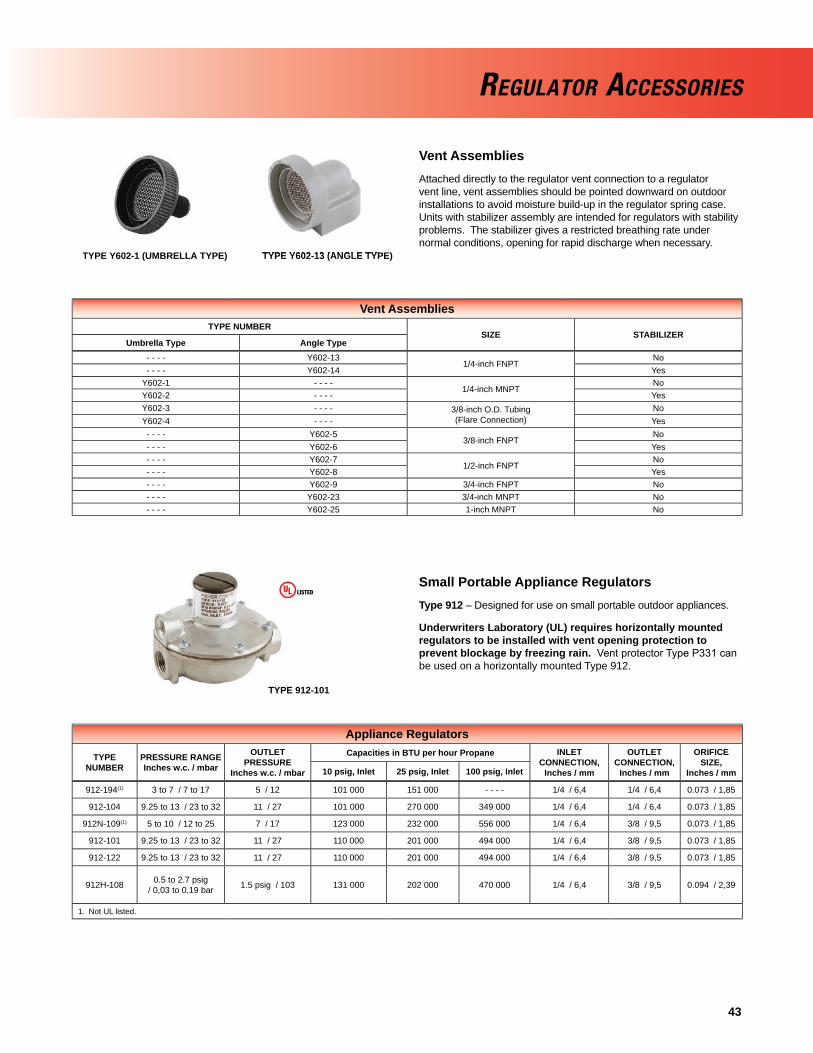
43
REGULATOR ACCESSORIES
Vent AssembliesAttached directly to the regulator vent connection to a regulator vent line, vent assemblies should be pointed downward on outdoor installations to avoid moisture build-up in the regulator spring case. Units with stabilizer assembly are intended for regulators with stability problems. The stabilizer gives a restricted breathing rate under normal conditions, opening for rapid discharge when necessary.
Small Portable Appliance RegulatorsType 912 – Designed for use on small portable outdoor appliances.
Underwriters Laboratory (UL) requires horizontally mounted regulators to be installed with vent opening protection to prevent blockage by freezing rain. Vent protector Type P331 can be used on a horizontally mounted Type 912.
Vent AssembliesTYPE NUMBER
SIZE STABILIZERUmbrella Type Angle Type
- - - - Y602-131/4-inch FNPT
No- - - - Y602-14 Yes
Y602-1 - - - -1/4-inch MNPT
NoY602-2 - - - - YesY602-3 - - - - 3/8-inch O.D. Tubing
(Flare Connection)No
Y602-4 - - - - Yes- - - - Y602-5
3/8-inch FNPTNo
- - - - Y602-6 Yes- - - - Y602-7
1/2-inch FNPTNo
- - - - Y602-8 Yes- - - - Y602-9 3/4-inch FNPT No- - - - Y602-23 3/4-inch MNPT No- - - - Y602-25 1-inch MNPT No
TYPE Y602-1 (UMBRELLA TYPE) TYPE Y602-13 (ANGLE TYPE)TYPE Y602-13 (ANGLE TYPE)
Appliance Regulators
TYPENUMBER
PRESSURE RANGEInches w.c. / mbar
OUTLETPRESSURE
Inches w.c. / mbar
Capacities in BTU per hour Propane INLETCONNECTION,
Inches / mm
OUTLETCONNECTION,
Inches / mm
ORIFICESIZE,
Inches / mm10 psig, Inlet 25 psig, Inlet 100 psig, Inlet
912-194(1) 3 to 7 / 7 to 17 5 / 12 101 000 151 000 - - - - 1/4 / 6,4 1/4 / 6,4 0.073 / 1,85
912-104 9.25 to 13 / 23 to 32 11 / 27 101 000 270 000 349 000 1/4 / 6,4 1/4 / 6,4 0.073 / 1,85
912N-109(1) 5 to 10 / 12 to 25 7 / 17 123 000 232 000 556 000 1/4 / 6,4 3/8 / 9,5 0.073 / 1,85
912-101 9.25 to 13 / 23 to 32 11 / 27 110 000 201 000 494 000 1/4 / 6,4 3/8 / 9,5 0.073 / 1,85
912-122 9.25 to 13 / 23 to 32 11 / 27 110 000 201 000 494 000 1/4 / 6,4 3/8 / 9,5 0.073 / 1,85
912H-108 0.5 to 2.7 psig / 0,03 to 0,19 bar 1.5 psig / 103 131 000 202 000 470 000 1/4 / 6,4 3/8 / 9,5 0.094 / 2,39
1. Not UL listed.
TYPE 912-101
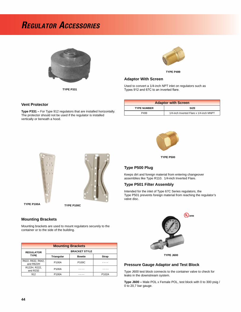
44
REGULATOR ACCESSORIES
Vent ProtectorType P331 – For Type 912 regulators that are installed horizontally. The protector should not be used if the regulator is installed vertically or beneath a hood.
TYPE P331
Adaptor With ScreenUsed to convert a 1/4-inch NPT inlet on regulators such as Types 912 and 67C to an inverted fl are.
Type P500 PlugKeeps dirt and foreign material from entering changeover assemblies like Type R110. 1/4-inch Inverted Flare.
Type P501 Filter AssemblyIntended for the inlet of Type 67C Series regulators, the Type P501 prevents foreign material from reaching the regulator’s valve disc.
Mounting BracketsREGULATOR
TYPEBRACKET STYLE
Triangular Bowtie StrapR622, R632, R642,
and R622H P100A P100C - - - -
R122H, R222, and R232 P100A - - - - - - - -
912 P100A - - - - P102A
Adaptor with ScreenTYPE NUMBER SIZE
P499 1/4-inch Inverted Flare x 1/4-inch MNPT
TYPE P100A TYPE P100C
TYPE P499
TYPE P500
Mounting BracketsMounting brackets are used to mount regulators securely to the container or to the side of the building.
Pressure Gauge Adaptor and Test BlockType J600 test block connects to the container valve to check for leaks in the downstream system.
Type J600 – Male POL x Female POL, test block with 0 to 300 psig / 0 to 20,7 bar gauge.
TYPE J600

45
REGULATOR ACCESSORIES
Test Gauge AssembliesThe 50 Series test gauges are used to check appliance line pressure after the regulator has been installed.
Pressure GaugesFisher® brand offers pressure gauges with bottom, back, or top connection for LP-Gas service. The back connection makes a more compact assembly on installations where space is limited.All gauges have a 2-inches (51 mm) diameter face/black Terluran®
plastic case.
TYPE 50-2 TYPE 50P-2
TYPE 50P-5
TYPE P400 TEE BLOCK
TYPE P414 TEE CHECK
BOTTOM CONNECTION BACK CONNECTION
Tee Blocks and ChecksTYPE OF MANIFOLD PIGTAIL
OR PIPING CONNECTION
REGULATORCONNECTION,
INCHESTee Block
(Without Check) Tee Check
P403 - - - -
Female POL
Female POL
P400 P410 Male POL
- - - - P413 1/4 MNPT
- - - - P414 1/4-inchInverted Flare 1/4 MNPT
Test Gauge Assemblies
TYPENUMBER
INLETCONNECTION HOSE PLASTIC
RANGE,INCHES W.C. /
mbar
50-2 1/4-inchMNPT No No
0 to 35/ 0 to 8750P-2
Female HoseYes Yes
50P-5 Yes No
Pressure GaugesPRESSURE GAUGE RANGE, psig / bar
Connection Size 0 to 15 / 0 to 1,0
0 to 30 / 0 to 2,1
0 to 60 / 0 to 4,1
0 to 160/ 0 to 11
0 to 300 / 0 to 20,7
0 to 400 / 0 to 27,6
Bottom 1/4-inch J500 J501 J502 J504 J506 J542/ 1
Back 1/4-inch J510 J511 J512 J514 J516 N/A
1. For LP-Gas or Anhydrous ammonia (NH3) service.
TYPE P414 TEE CHECK
BOTTOM CONNECTION
Tee Blocks and ChecksTee blocks are a 3-way POL connection that allows connection of two containers to a regulator inlet.
Tee checks allow the connection of two containers to a regulator inlet. A check disc inside the Tee check body permits fl ow only from the container with the highest vapor pressure.
Terluran® is a trademark of BASF.

46
1 VALVE CLOSE 2 JET BLEED 3 VALVE OPEN 4 LIMITED BLEED EQUALIZATION
Fisher® brand internal valves have gained wide field acceptance for use as primary shutoff valves, excess flow valves and back check valves(1). Internal valves are installed in the inlets and outlets (liquid or vapor) of pressure vessels and in piping systems to control the flow of LP-Gas and NH3 (anhydrous ammonia). The most frequent application is on bobtail and transport truck tanks, but they may also be used on large stationary storage tanks and on in-line installations. The valves can be used in conjunction with or without pumps and compressors.
Features and BenefitsPatented rapid equalization bleed area*• —provides fast valve response for quick opening.
Unique Serviceability Features*• —Removable gland packing, stainless trim parts, and poppet designed with integral wrench flat for easy maintenance.
Durable Design• —Stainless poppet and stem* interface smoothly for a long wear life.
Excess Flow Closure• —Functions when flow exceeds the valves rated capacity or piping is sheared off at the valve.
Back Check Feature• —Allows reverse flow, fill with or without actuator device in valve open position.
Spring loaded PTFE stub shaft packing•
PTFE wear pads and Rulon• TM Bushings at critical wear points
Manual, Cable or Air Open/Close Control•
Thermal Fusible links or plugs melt at 212° to 220°F / 100° to 104°C and allow valve closure in the event of a fire at the valve.•
Principle of OperationThe operational schematic below depicts threaded valves, however flanged styles operate in the same manner. For detailed information, refer to the Instruction Manual provided with the valve.
View #1 The valve is held closed by both tank pressure and the valve’s closing spring. There is no leakage past the resilient seats in the poppet to the valve outlet.
View #2 The valve is opened by moving the operating lever to approximately midpoint in its 70° travel. This allows the cam to place the rapid equalization portion of the valve stem in the pilot opening, permitting a larger amount of product to bleed downstream than if the operating lever were moved to the full open position.
View #3 When tank and downstream pressure are nearly equal after a few
INTERNAL VALVES
seconds, the excess flow spring pushes open the main poppet and the operating lever can be moved to the full open position.
If tank pressure is greater than the valve’s outlet pressure, the main poppet will remain in the closed position. If valve outlet piping is closed off by other valves, however, product bleeding through the pilot will increase until it nearly equals tank pressure and the main poppet opens. The main poppet will not open if valve outlet piping is not closed off so that the outlet pressure can approach tank pressure.
View #4 Once the main poppet opens, a flow greater than the valve’s excess flow spring rating or a sufficient surge in flow forces the main poppet closed against the excess flow spring. The pilot valve allows a small amount of product to bleed, but much less than view # 2 where the rapid equalization portion of the stem is placed in the pilot opening. When the operating lever is moved to the closed position, the valve closes completely and seals tightly (view #1).
1. Because of the integral back check function of these valves, selective filling of manifold storage tanks requires the use of additional shutoff valves.
jeT BLEED
lIMITed BLEED
lIMITed BLEED
FLOW
LIMITED BLEED
JET BLEED EQUALIZATIONVALVE OPEN FLOW
FLOWjeT BLEED
* Unique to the jet Bleed Internal™ Valve design only.

47
THREADED INTERNAL VALVES
Threaded Internal ValvesRegulator Technologies offers the widest variety of threaded internal valves in the industry. While their most frequent use is in the liquid and vapor openings of bobtail and transport trucks, the valves can also be used in stationary storage tanks, complying with NFPA 58 requirements. designed as primary shutoff valves, the units are designed with several features that help control product discharge.
Steel and stainless steel constructions are standard throughout with total stainless steel construction available. The valves have spring-loaded PTFe packing for an effective seal against leakage. Standard disc material is Nitrile (NBR), but PTFe, Perfl uoroelastomer (FFKM), Fluorocarbon (FKM), ethylenepropylene (ePdM), and Neoprene are available. (Note: PTFe seats are not bubble tight.)
All Fisher® brand internal valves are suitable for lP-Gas or anhydrous ammonia (NH3) service. Special construction is available for other compressed gases. All threaded internal valves have a compact, one-piece body design. They can be actuated manually, by cable control, or with an air cylinder.
Threaded Internal ValvesCONNECTIONS
INLET X OUTLET
TYPE NUMBER CLOSING FLOW GPM / l/min PROPANE(2) VAPOR CAPACITY SCFH / SCMH PROPANE(2)
Straight Body Tee Body Half Coupling Full Coupling 25 psig / 1,7 bar Inlet 100 psig / 6,9 bar Inlet
1-1/4-inch MNPT x1-1/4-inch FNPT
C407-10-03- - - - 30 / 114 - - - - 5600 / 159 9300 / 263
C407M-10-03(1)
C407-10-05- - - - 50 / 189 35 / 133 7800 / 221 13 200 / 374
C407M-10-05(1)
C407-10-08- - - - 80 / 303 65 / 246 11 200 / 317 19 200 / 544
C407M-10-08(1)
2-inch MNPT x2-inch FNPT
C477-16-10 C471-16-10 100 / 379 60 / 227 26 100 / 739 45 000 / 1274
C477-16-15 C471-16-15 150 / 568 90 / 341 39 400 / 1116 69 000 / 1954
C477-16-25 C471-16-25 250 / 946 130 / 492 - - - - - - - -
3-inch MNPT x3-inch FNPT
C477-24-16 C471-24-16 160 / 606 120 / 454 41 100 / 1164 71 000 / 2011
C477-24-26 C471-24-26 265 / 1003 230 / 871 71 800 / 2033 127 000 / 3596
C477-24-37 C471-24-37 375 / 1419 320 / 1211 99 000 / 2803 178 000 / 5040
C477-24-46 C471-24-46 460 / 1741 380 / 1438 - - - - - - - -
1. Includes a factory installed Type P340 / P341 latch. 2. Closing Flows and Vapor Capacities listed are with valve in “bottom of tank” position. See product bulletins for additional data.
C407 SERIES
C407-10 Series (1-1/4-inch / DN 32 Body Size) – An excellent valve for vapor return lines on bobtail trucks. Other applications include use as a main valve on small capacity pumping systems, anhydrous ammonia (NH3) nurse tanks and in-line installations.
C400 Series (2 and 3-inch Body Sizes)Regulator Technologies offers three different body styles in 2 and 3-inch NPT sizes so that the best body style can be selected for the particular application.
C477 Series (Straight-Through Body) – The most compact and economical unit in the Series, the C477 Series has one bottom outlet. The C477 Series can be used on bobtail, transport, stationary tank and in-line installations.
C471 Series (Tee Body) – This unit is designed with two outlets, bottom and side. The side outlet permits installing horizontal piping immediately adjacent to the tank without the need for extra pipe fi ttings. either connection can be used for truck fi lling or withdrawal. The C471 Series is used primarily on bobtails and transport trucks.
C477 SERIES C471 SERIES

48
“BOTTOM OF TANK” POSITION
“TOP OF TANK” POSITION
“HORIZONTAL” POSITION
INTERNAL VALVE TANK POSITIONS
THREADED INTERNAL VALVES

49
Threaded Valve Specifications
Pressure Rating: 400 psig / 27,6 bar WOG Temperature: Up to 150°F / 66°CBody: ductile iron (C471 and C477 Series) Cast steel (C407-10 Series)Packing: PTFeSeat Discs: Synthetic rubberStub Shaft and Stem: Stainless steel
A line break downstream of a pump may not actuate the excess flow valve. If any break occurs in the system or if the excess flow valve closes, the system should be shutdown immediately.
THREADED INTERNAL VALVES
FLOW RATE, GPM / l/min PROPANE
VALV
ED
IFFE
REN
TIA
LPR
ESSU
RE,
psi
g / b
ar
DO NOT USE the excess flow function incorporated into Fisher® C Series internal valves or F Series excess flow valves to satisfy the passive shutdown requirement in 49CFR§173.315(n)(2). DO NOT include the excess flow incorporated into Fisher C Series internal valves or F Series excess flow valves in a DCE certification under 49CFR§173.315(n)(2). The cargo tank manufacturer must install some other equipment that satisfies the requirement for passive shutdown capability under 49CFR§173.315(n)(2).
Failure to follow this warning could result in serious personal injury or property damage from fire or explosion in the event of an unintentional release of product during an unload operation.
C477/471-24 “Bottom of Tank” Position Flow Curve, Half Coupling
0
2
4
6
8
10
12
14
16
18
20
0 50 100 150 200 250 300 350 400
Valv
eD
ifffef
rernt
ialP
ress
ure,
psig
Flow, GPM Propane
C477-24-36VeVV rtical Up Position
111.8888883332.5114
V VVa VVaal aav ll
vve vveeD DD
i DDf iifff fffffffff ffff
e ffeeffffffr eerre rreerrrrr rrr
n eennt nntti tta iiaa
l aaP PPr PP
rre rreer rrrs eess
s ssssu ssuu
r uurre rree
, eep pps pp
ssi ssg iigg
CCC444777777-122644-133066VVVeVVeeVVVVVVVV rrrtrrttrrrrrrrr iiicccaaalll UUUppp PPPooosssiiitttiiiooonnn
Unit 1Unit 1
UUniitt 33
50/ 189
150/ 568
200/ 757
250/ 946
300/ 1136
350/ 1325
400/ 1514
100/ 379
00
20/ 1,4
18/ 1,2
16/ 1,1
14/ 0,97
12/ 0,83
10/ 0,69
8/ 0,55
6/ 0,41
4/ 0,28
2/ 0,14
450/ 1703
! WARNING
160 GPM / 605 l/min Rating265 GPM / 1003 l/min Rating375 GPM / 1419 l/min Rating460 GPM / 1741 l/min Rating
0
2
4
6
8
10
12
14
16
18
20
0 50 100 150 200 250 300 350 400
Valv
eD
iffffeff
rerrnt
ialP
ress
ure,
psig
Flow, GPM Propane
C477-24-36VeVV rtrr ical Up Position
Unit 1

50
THREADED INTERNAL VALVES
0
2
4
6
8
10
12
14
16
18
20
0 50 100 150 200 250 300
Valv
eD
ifffef
rernt
ialP
ress
urer
,psi
g
Flow, GPM Propane
C477-16-25Vertrr ical Up Position
21.2211
77.93
2.3671
2211
2
.0
1.3251111.888888883333
2.514
VVV aVVaa lll
vllvv evvee
DDDiii fiiff fffffffff fffff
effeeffff fffrrr erreerrrr rrrr
nnn tnntt ittii aiiaa
lll PPP rrr
erreeseess
sssssuuu r
rr erreerrrr rrrr,e,,
ppp sppss iii
giigg
CCC444777777---111666---122055VVVeVVVeeeVeerrrttrrrrtttrttttiiicccaaalll UUUppp PPPooosssiiitttiiiooonnn
Unit 1
UUUnit 3
C477/471-16 “Bottom of Tank” Position Flow Curve, Half Coupling
FLOW RATE, GPM / l/min PROPANE
0
20/ 1,4
18/ 1,2
16/ 1,1
14/ 0,97
12/ 0,83
10/ 0,69
8/ 0,55
6/ 0,41
4/ 0,28
2/ 0,14
VALV
ED
IFFE
REN
TIA
LPR
ESSU
RE,
psi
g / b
ar
50/ 189
150/ 568
200/ 757
250/ 946
300/ 1136
100/ 379
0
C477-24 Typical Reverse Flow Curve
VALVE CLOSED POSITION
VALVE OPEN POSITION
FLOW RATE, GPM / l/min PROPANE
VALV
ED
IFFE
REN
TIA
LPR
ESSU
RE,
psi
g / b
ar
50/ 189
150/ 568
200/ 757
250/ 946
300/ 1136
350/ 1325
400/ 1514
450/ 1703
500/ 1893
550/ 2082
600/ 2271
650/ 2460
700/ 2650
100/ 379
00
5 / 0,35
10 / 0,69
35 / 2,4
15 / 1,0
20 / 1,4
25 / 1,7
30 / 2,1
40 / 2,8
C477-16 Typical Reverse Flow Curve
VALVE OPEN POSITION
VALVE CLOSED POSITION
FLOW RATE, GPM / l/min PROPANE
VALV
ED
IFFE
REN
TIA
LPR
ESSU
RE,
psi
g / b
ar
50/ 189
150/ 568
200/ 757
250/ 946
300/ 1136
350/ 1325
100/ 379
00
5 / 0,35
10 / 0,6915 / 1,020 / 1,425 / 1,7
30 / 2,135 / 2,4
40 / 2,845 / 3,150 / 3,4
55 / 3,8
105 GPM / 397 l/min Rating150 GPM / 567 l/min Rating250 GPM / 946 l/min Rating
0
2
4
6
8
10
12
14
16
18
20
0 50 100 150 200 250 300
Valv
eD
ifffef
rernt
ialP
ress
urer
,psi
g
Flow, GPM Propane
C477-16-25Vertrr ical Up Position
21.2211
77.93
2.3671
2211
2
.0
1.3251111.888888883333
2.514
VVV aVVaa lll
vllvv evvee
DDDiii fiiff fffffffff fffff
effeeffff fffrrr erreerrrr rrrr
nnn tnntt ittii aiiaa
lll PPP rrr
erreeseess
sssssuuu r
rr erreerrrr rrrr,e,,
ppp sppss iii
giigg
CCC444777777---111666---122055VVVeVVVeeeVeerrrttrrrrtttrttttiiicccaaalll UUUppp PPPooosssiiitttiiiooonnn
Unit 1
UUUnit 3

51
Threaded Valves
TYPENUMBER
A, INCH(FNPT)
B, INCH(MNPT)
DIMENSIONS, INCHES / mmINSTALLATION CLEARANCE
DIAMETER, INCHES / mmC D E F H
C407-10 1.25 1.25 5.90 / 150 1.86 / 47 2.88 / 73 - - - - - - - - 5.00 / 127
C471-16 2 2 8.07 / 205 2.40 / 61 4.05 / 103 2.76 / 70 2.66 / 68 10.00 / 254
C471-24 3 3 9.00 / 229 2.60 / 66 4.57 / 116 3.25 / 83 3.26 / 83 13.38 / 340
C477-16 2 2 8.07 / 205 2.40 / 61 4.05 / 103 - - - - - - - - 10.00 / 254
C477-24 3 3 9.00 / 229 2.60 / 66 4.57 / 116 - - - - - - - - 13.38 / 340
THREADED INTERNAL VALVES
A - FNPT
SWING
C407-10 SERIES C477 SERIES
B - MNPT
APPROXIMATE TOPOF BOSS
OR COUPLING
CCLOSED
E
D
70°
C1/4-INCH
B-MNPT
D
E
A - FNPT
SWING70°
APPROXIMATE TOPOF BOSS ORCOUPLING
In-Line Adaptors
ZDIMENSIONS, INCHES / mm
X Y D
1-1/4-inch FNPT 4.70 / 119 2.75 / 70 2.05 / 52
2-inch FNPT 6.77 / 172 3.5 / 89 2.80 / 71
3-inch FNPT 7.53 / 191 4.5 / 114 3.80 / 97
D
IN-LINE ADAPTOR
Z
X
Y
E
1/4-INCH FNPT
APPROXIMATE TOP OF BOSS OR COUPLING
70° SWING
D
H
A
A
B
CCLOSED
C471 SERIES
F

52
Flanged Internal ValvesFlanged valves provide a sturdy and compact means of directly mounting a pump or piping connection. Special stud bolts, weakened with a groove on the outside diameter, are furnished with the valves to permit the pump or piping to shear off in the event of an accident, leaving the valve intact. A built-in excess fl ow valve reduces the chance of uncontrolled product discharge when fl ow exceeds the rated fl ow capacity.
All fl anged valves have an internal screen for pump protection that can be easily removed if the valve is used primarily for fi lling the tank. They also contain PTFe packing to resist stub shaft leakage. These valves can be activated manually, by cable control or by air cylinder (refer to pages 58 and 59).
3-inch / DN 80 Flanged SizesType C484-24 – A single-fl ange unit widely used on bobtail and transport trucks for a compact means of direct pump connection to the valve outlet. Another application for the Type C484-24 is on in-line installations.
Type C483-24 – A double-fl ange unit designed for special bobtail truck applications where the pump must be lowered to clear the truck frame or other obstacles. A special shear section in the body permits the lower section of the valve to shear off in the event of an accident, leaving the critical shutoff parts within the tank.
FLANGED INTERNAL VALVES
3-inch / DN 80 Flanged Internal ValvesTYPE NUMBER CLOSING FLOW, GPM / l/min PROPANE CLOSING FLOW, GPM / l/min NH3
Single Flange Double Flange Single Flanged,Bottom of Tank Position
Double Flanged,Bottom of Tank Position
Top of Tank Position,Single - Double Flanged
Single - Double Flanged,Bottom of Tank Position
C484-24-16 C483-24-16 160 / 606 160 / 606 180 / 681 - 180 / 681 144 / 545 - 144/ 545
C484-24-25 C483-24-26 250 / 946 265 / 1003 250 / 946 - 290 / 1098 239 / 905 - 226 / 855
C484-24-40 C483-24-40 400 / 1514 400 / 1514 400 / 1514 - 400 / 1514 361 / 1366 - 361 / 1366
VAPOR CAPACITY SCFH / SCMH PROPANE
100 psig / 6,9 bar Inlet,Single - Double Flanged, Standard Position
100 psig / 6,9 bar Inlet,Single - Double Flanged, Inverted Position
C484-24-16 C483-24-16 71 000 / 0,8 - 71 000 / 0,8 96 000 / 1,1 - 96 000 / 1,1
C484-24-25 C483-24-26 NOT lISTed - 127 000 / 1,4 NOT lISTed - 148 000 / 1,6
C484-24-40 C483-24-40 181 000 / 2,0 - 181 000 / 2,0 190 000 / 2,1 - 190 000 / 2,1
TYPE C483-24 TYPE C484-24

53
FLANGED INTERNAL VALVES
Types C483-24 and C484-24 Typical Closing Flow Curve, Standard Position
VALV
E D
IFFE
REN
TIA
L PR
ESSU
RE,
psi
g / b
ar
FLOW RATE, GPM / l/min PROPANE
0
2
4
6
8
10
12
14
16
18
20
0 50 100 150 200 250 300 350 400
Valv
eD
ifffef
rernt
ialP
ress
ure,
psig
Flow, GPM Propane
C477-24-36VeVV rtical Up Position
111.8888883332.5114
V VVa VVaal aav ll
vve vveeD DD
i DDf iifff fffffffff ffff
e ffeeffffffr eerre rreerrrrr rrr
n eennt nntti tta iiaa
l aaP PPr PP
rre rreer rrrs eess
s ssssu ssuu
r uurre rree
, eep pps pp
ssi ssg iigg
CCC444777777-122644-133066VVVeVVeeVVVVVVVV rrrtrrttrrrrrrrr iiicccaaalll UUUppp PPPooosssiiitttiiiooonnn
Unit 1Unit 1
UUniitt 33
20/ 1,4
18/ 1,2
16/ 1,1
14/ 0,97
12/ 0,83
10/ 0,69
8/ 0,55
6/ 0,41
4/ 0,28
2/ 0,14
400/ 1514
350/ 1325
300/ 1136
250/ 946
200/ 757
150/ 568
100/ 379
50/ 189
0
0
450/ 1703
Flanged Valve SpecificationsPressure Rating: 400 psig / 27,6 bar WOG Temperature: Up to 150°F / 66°CBody: Cast steel, WCC (Types C483 and C484-24) Stainless steel (Type C484-32)Packing: PTFeSeat Discs: Synthetic rubberStub Shaft and Stem: Stainless steelGaskets: Non-asbestos spiral wound graphite
A line break downstream of a pump may not actuate the excess flow valve. If any break occurs in the system or if the excess flow valve closes, the system should be shutdown immediately.
DO NOT USE the excess flow function incorporated into Fisher® C Series internal valves or F Series excess flow valves to satisfy the passive shutdown requirement in 49CFR§173.315(n)(2). DO NOT include the excess flow incorporated into Fisher C Series internal valves or F Series excess flow valves in a DCE certification under 49CFR§173.315(n)(2). The cargo tank manufacturer must install some other equipment that satisfies the requirement for passive shutdown capability under 49CFR§173.315(n)(2).
Failure to follow this warning could result in serious personal injury or property damage from fire or explosion in the event of an unintentional release of product during an unload operation.
! WARNING
0
2
4
6
8
10
12
14
16
18
20
0 50 100 150 200 250 300 350 400
Valv
eD
ifffef
rernt
ialP
ress
ure,
psig
Flow, GPM Propane
C477-24-36VeVV rtical Up Position
111.8888883332.5114
V VVa VVaal aav ll
vve vveeD DD
i DDf iifff fffffffff ffff
e ffeeffffffr eerre rreerrrrr rrr
n eennt nntti tta iiaa
l aaP PPr PP
rre rreer rrrs eess
s ssssu ssuu
r uurre rree
, eep pps pp
ssi ssg iigg
CCC444777777-122644-133066VVVeVVeeVVVVVVVV rrrtrrttrrrrrrrr iiicccaaalll UUUppp PPPooosssiiitttiiiooonnn
Unit 1Unit 1
UUniitt 33
160 GPM / 606 l/min RATING
250 GPM / 946 l/min RATING (TYPE C484 ONLY)
265 GPM / 1003 l/min RATING (TYPE C483 ONLY)
400 GPM / 1514 l/min RATING

54
TYPE C404-32 TYPE C404A32
TYPE C404-32 CAPACITY CURVE
TYPE C404M32
4-inch / DN 100 Flanged Size (Stainless Steel Construction)Type C404-32 – Used widely on transport trucks and large storage tanks, the 4-inch / dN 100 fl anged unit comes standard with all stainless steel construction for maximum protection against rust and corrosion. For easy fi eld maintenance, the seat ring is fi eld replaceable.
4-inch / DN 100 Flanged Internal ValvesTYPE NUMBER(1)
INLET, INCHES / DN
OUTLET,INCHES / DN
CLOSING FLOW,GPM / l/min PROPANE(2)
VAPOR CAPACITY ,SCFH / SCMH PROPANE
Cable Air Manual 25 psig / 1,7 bar Inlet
100 psig / 6,9 barInlet
C404-32-34 C404A-32-34 C404M-32-34
4 / 100 Cl300ASMe RF Modifi ed
5-7/8 / 149 mm diameter bore
4 / 100 Cl300 ASMe RF
340 / 1287 61 600 / 1745 104 800 / 2968
C404-32-40 C404A-32-40 C404M-32-40 400 / 1514 63 900 / 1810 108 600 / 3076
C404-32-60 C404A-32-60 C404M-32-60 600 / 2271 83 200 / 2356 141 500 / 4007
C404-32-80 C404A-32-80 C404M-32-80 800 / 3028 259 600 / 7352 356 200 / 10 088
C404-32-100 C404A-32-100 C404M-32-100 1000 / 3785 - - - - - - - -
1. 4-inch / dN 100 size available in single fl ange only. 2. Closing fl ow vertical down.
The Type C404-32 is the only internal valve that cannot be opened and closed by the Type P650 cable control (refer to page 59).
Factory installation of an air cylinder or manual operating handle (with remote release mechanism) is available on the 4-inch / dN 100 fl anged valves. Refer to ordering information below.
FLOW, GPM / l/min PROPANE
200/ 757
300/ 1136
400/ 1514
500/ 1893
600/ 2271
700/ 2650
800/ 3028
900/ 3407
1000/ 3785
100/ 379
00
8/ 0,55
9/ 0,62
6/ 0,41
7/ 0,48
4/ 0,28
5/ 0,35
1/ 0,07
2/ 0,14
3/ 0,21
VALV
E D
IFFE
REN
TIA
L PR
ESSU
RE,
psi
g / b
ar
FLANGED INTERNAL VALVES

55
C
B
A
E
6” STUD(8 REQUIRED)
D
In-Line Piping
ADIMENSIONS, INCHES / mm OUTLET
B C D E
ASME CL300 RF Flange Pipe Size Reducer Minimum ASME CL300 RF Flange
3-inch / dN 80 6 / 152 6 x 3 / 152 x 76 7.9 / 201 3-inch / dN 80
4-inch / dN 100 8 / 203 8 x 4 / 203 x 102 11.5 / 292 4-inch / dN 100
O.D. AND THICKNESS TO SUITCONTAINER SPECIFICATIONS
45°
MAX.1 / 25 MIN.
3/4 / 19 -10 UNCE
B
A
C
D
Studding Outlet
FLANGED INTERNAL VALVES
INCHES/ mm
Tank Connections
MODIFIEDCL300 ASME RF
FLANGE
DIMENSIONS, INCHES / mm MATINGFlANgE O.D., INCHES / mm
A BRF
CRF D E
DBC No. Size3-inch / dN 80 6.62 8 0.75 5.75 / 146 0.06 / 1,5 1.50 / 38 4.62 / 117 8.25 / 210
4-inch / dN 100 7.88 8 0.75 7.00 / 178 0.06 / 1,5 1.56 / 40 5.88 / 149 10.00 / 254

56
FLANGED INTERNAL VALVES
3-INCH / DN 80CL300 ASME RF FLANGE MODIFIED [4.62 / 117 DIAMETER BORE AND 5.75 / 148 mm RF]
70°SWING
A
B
4-INCH / DN 100 CL300 ASME RF FLANGE MODIFIED [5.88 / 149 DIAMETER BOREAND 7.00 RF]
A
B
1.56 / 39,6
4-INCH / DN 100CL300 ASME RF FLANGE
3-INCH / DN 80 CL300ASME RF FLANGEMODIFIED [4.62 / 117 DIAMETER BORE AND 5.75 / 148 mm RF]
70°
A
B
SWING
TYPE C484-24 TYPE C483-24
TYPE C404-32
Flanged Valves
TYPE NUMBER TANK CONNECTIONS,INCHES / DN
DIMENSIONS,INCHES / mm
A B
C484-24 3 / 80Cl300 RF Flange
6.75/ 171
2.56/ 65
C483-24 3 / 80 Cl300 RF Flange
5.33/ 135
5.62/ 143
C404-32 4 / 100 Cl300 RF Flange
7.55/ 192
3.48/ 88

57
Air Interlock SystemsAn air interlock system can be configured for transport and bobtail trucks with air brakes by using air cylinder actuated internal valves. This system simultaneously interlocks the internal operation with the truck air brakes without affecting normal air brake operation. It complies with dOT MC331 and NFPA 58 requirements regarding thermal and remote release feasibility.
AIR INTERLOCK HOOK-UP ON TRANSPORT TRUCK
AIR INTERLOCK HOOK-UP ON BOBTAIL TRUCK
INTERNAL VALVE CONTROLS
The air interlock system permits the air brakes to set before the internal valve opens – even if the truck operator forgets to set the brakes. The brakes cannot be released until the internal valve is closed.
In addition, a 4–way actuating valve can be used with Type C404A32 to pressure both sides of the air cylinder depending upon the position of the operating handle. This allows air pressure to close as well as to open the internal valve.
Brakeactuators(part of
brake system)
Relayvalve
Two-waycheck valve
Backpressurevalve Fuse
plugCylinderactuator
Service line
Internalvalve
Fuse plug
Emergency valve(hand valve)
Fuseplug
Four-wayactuating valve
Brake actuators(part of truck
air brakesystem)
Reservoir(part of truck air brake system)
To Port 1 connectionon actuating valve
Line fromcompressor
(supply)
Brake line(service)
Relayvalve
Two-waycheck valve
Backpressurevalve
Cylinderactuator Internal
valve
Fuse plug
Emergencyvalve
(hand valve)
Four-wayactuating valve
Fuse plug
Fuseplug

58
Cable ControlsFisher® brand cable controls and accessories can be furnished to remotely open and close all internal valves except the 4-inch / dN 100 fl anged size. This equipment can be used to comply with NFPA 58 and dOT requirements for MC331 cargo tanks.
Cable systems can also be used on stationary storage tanks at bulk plants and on in-line applications to increase safety during transfer operations. All fusible elements and links used in the cable control systems comply with NFPA 58 and MC331 requirements.
Type P650 or P651 Primary Cable Control – Capable of actuating all Fisher brand internal valves except the 4-inch / dN 100 Type C404-32, the Type P650 or P651 opens and closes the valve from a remote point, usually the rear of the bobtail or transport. Pulling the handle of the primary control opens the internal valve; pushing the handle closes the valve. There are three notches on the primary control that give a travel of 4, 5, or 6-inch / 102, 127, or 152 mm depending upon the travel required by the valve’s operating lever.
Included with each Type P650 primary control is a 20-foot / 6,1 m cable, Type P134 fusible links, a return spring and mounting hardware. If just the primary cable control is needed, order Type P651, which is available without any of the other accessories.
Type P163A or P164A Auxiliary Remote Release – These units allow the internal valve to be closed from a location other than the primary control point (Type P650 or P651). Pulling the auxiliary release handle trips the release mechanism on the primary control to close the internal valve.
The two assemblies are identical except for the length. Type P163A has an untrimmed length of 25 feet / 7,6 m and Type P164A has an untrimmed length of 50 feet / 15,2 m. Both cables can be trimmed to any length. Both releases can be installed through mounting brackets up to 3/8-inch / 9,5 mm thick.
INTERNAL VALVE ACCESSORIES
Internal Valve AccessoriesINTERNAL VALVE SIZE,
INCHES / DNPRIMARY CABLE
CONTROLAUXILIARY REMOTE
RELEASECABLE
ASSEMBLYLATCH/RELEASE
MECHANISM
1-1/4, 2, and 3 / 32, 50, and 80
(NPT or Flanged)Type P650 or P651(1) Type P163A or P164A Included
with Type P650
Type P341, P342 (C407-10 Series)
Type P340 (C400 Series)
4 / 100 Flanged Use Allegheny orWheaton Control Type P315 Type P314 Type P313(2)
1. Type P651 is a primary control only, no accessories. 2. Use with Type P315 remote release mechanism.
TYPE P650 TYPE P340TYPE P341 TYPE P313
Type P164B – a release assembly that uses 50 feet / 15 m of cable housing which does not require elaborate guiding like uncovered cables.
Type P164C – an Auxiliary Remote Release without cable is also available.
Latch/Remote Release MechanismsWith the exception of the 3-inch / dN 80 fl anged sizes, all Fisher brand internal valves can be fi tted with a manual latch/remote release mechanism. When the internal valve’s operating lever is manually moved to the open position, the lever can be latched in the open position. The lever can be released from a remote location by pulling on the cable attached to a pull ring, thus closing the internal valve. A built-in fusible element in the latch/release melts if exposed to fi re allowing the operating lever to return to the closed position.
Type P340 – Fits all 2 and 3-inch NPT internal valves (Types C471 and C477). Type P340 is easily installed in the fi eld by removing two of the three gland cap screws.
Type P341 – Fits 1-1/4-inch NPT C407 Series internal valves. Also available factory installed, Type C407M10.
Type P342 – Bi-directional latch/remote release for the 1-1/4-inch NPT C407-10 Series allows operation from two directions.
Type P313 – Fits 4-inch / dN 100 Type C404-32 internal valves. Also available factory installed, Type C404M32. The Type P315 remote release should be used with this release.
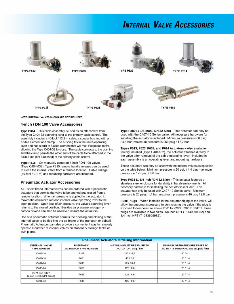
59
4-inch / DN 100 Valve AccessoriesType P314 – This cable assembly is used as an attachment from the Type C404-32 operating lever to the primary cable control. The assembly includes a 40-foot / 12,2 m cable, a special bushing with a fusible element and clamp. The bushing fi ts in the valve-operating lever and has a built-in fusible element that will melt if exposed to fi re, allowing the Type C404-32 to close. The cable connects to the bushing and the clamp permits the other end of the cable to be attached to the fusible link (not furnished) at the primary cable control.
Type P315 – On manually actuated 4-inch / dN 100 valves (Type C404M32), Type P315 remote handle release can be used to close the internal valve from a remote location. Cable linkage (30 feet / 9,1 m) and mounting hardware are included.
Pneumatic Actuator AccessoriesAll Fisher® brand internal valves can be ordered with a pneumatic actuators that permits the valve to be opened and closed from a remote location. When air pressure is applied to the actuator, it moves the actuator’s rod and internal valve operating lever to the open position. Upon loss of air pressure, the valve’s operating lever returns to the closed position. Besides air pressure, nitrogen or carbon dioxide can also be used to pressure the actuators.
Use of a pneumatic actuator permits the opening and closing of the internal valve to be tied into the air brake of the transport or bobtail. Pneumatic Actuators can also provide a convenient way to remotely operate a number of internal valves on stationary storage tanks at bulk plants.
Type P389 (1-1/4-inch / DN 32 Size) – This actuator can only be used with the C407-10 Series valve. All necessary hardware for installing the actuator is included. Minimum pressure is 60 psig / 4,1 bar; maximum pressure is 250 psig / 17,2 bar.
Types P613, P623, P639, and P614 Actuators – Also available factory installed (Type C404A32), the actuator attaches directly to the valve after removal of the cable-operating lever. Included in each assembly is an operating lever and mounting hardware.
These actuators can only be used with the internal valves as specifi ed on the table below. Minimum pressure is 20 psig / 1,4 bar; maximum pressure is 125 psig / 8,6 bar.
Type P631 (1-1/4 inch / DN 32 Size) – This actuator features a stainless steel enclosure for durability in harsh environments. All necesary hardware for installing the actuator is included. This actuator can only be used with C407-10 Series valve. Minimum pressure is 20 psig / 1,4 bar; maximum pressure is 40 psig / 2,8 bar.
Fuse Plugs – When installed in the actuator piping at the valve, will allow the pneumatic pressure to vent closing the valve if the plug is exposed to temperature above 208° to 220°F / 98° to 104°C. Fuse plugs are available in two sizes, 1/8-inch NPT (T1140399982) and 1/4-inch NPT (T1033699982).
Pneumatic Actuators Ordering InformationINTERNAL VALVE
TYPE NUMBERPNEUMATIC
ACTUATOR TYPE NUMBERMAXIMUM INLET PRESSURE TO
ACTUATOR, psig / barMINIMUM OPERATING PRESSURE TO
ACTIVATE INTERNAL VALVE, psig / bar
C407-10 P389 250 / 17,2 60 / 4,1
C407-10 P631 40 / 2,8 20 / 1,4
C484-24 P613 125 / 8,6 20 / 1,4
C483-24 P623 125 / 8,6 20 / 1,4
C471 and C477 (2 and 3-inch NPT Sizes) P639 125 / 8,6 20 / 1,4
C404-32 P614 125 / 8,6 20 / 1,4
INTERNAL VALVE ACCESSORIES
TYPE P315TYPE P315 TYPE P389
TYPE P613 TYPE P623 TYPE P614
TYPE P631TYPE P631
TYPE P639 TYPE P639
NOTE: INTERNAl VAlVES SHOWN ARE NOT INClUDED.

60
Snappy JoeTM Emergency Shutoff Valves for Bulk PlantsSnappy joeTM Type N550 emergency Shutoff Valves (eSVs) are designed for in-line installations, usually near a bulkhead. The valves provide a means of shutting off gas in the event of a hose rupture or piping break at the transfer area to avoid a large scale loss of lP-Gas or anhydrous ammonia (NH3).
The valves can be manually opened and closed at the installed location or closed remotely by either cable or air. A remote operating actuator is also available.
High Flow Capacity – The main poppet moves completely out of the fl ow stream for extremely low restriction-to-fl ow.
Operational Ease – Moving the operating lever to the vertical position opens the valve, making it simple to tell if the unit is open or closed. A pilot valve in the poppet opens as the lever is moved upward to pressurize the hose. Once equalized, the poppet moves quickly to the open position.
The valve is closed by simply pushing the lever down without fi rst having to trip a latch. The operating lever is easily reached from across a bulkhead. All sizes look similar and operate exactly the same, an important point in an emergency situation.
Fusible Element – The fusible element is located at the hub of the operating lever and stub shaft. When exposed to fi re, the element melts allowing the stub shaft to turn. The poppet then moves to the closed position, even if the operating lever has been wired open.
Rugged Construction – Heavy duty construction makes Snappy joeTM eSVs suitable for use as a “working” shutoff valve for the transfer area, even under frequent use. The internal closing spring is protected from the elements and tampering. All seats and seals use metal back-up seals for extended fi re resistance. The valves are rated 400 psig / 27,6 bar WOG.
Ease of Service – Serviceable without removal from the pipeline. Parts that wear are external and can be changed out in a matter of minutes. The packing can be changed with the valve in-line.
Cable Release – Standard valves are fi tted with a release mechanism for cable attachment. A cable connected to the wire loop allows closure from a safe remote location, such as the bulk plant entrance.
While the ordinary cable can be used, the Type P164B release assembly is available. This assembly uses 50 feet / 15 m of cable housing which does not require elaborate guiding like uncovered cables.
Pneumatic Operation – Remote pneumatic closure is available with Type P327D release. depending upon valve inlet pressure, a minimum supply pressure of 30 to 70 psig / 2,1 to 4,8 bar on the Type P327d allows the valve to be latched in the open position with manual closure possible at the valve. loss of supply pressure to the cylinder permits the eSV to close. Air, nitrogen, or CO2 can be used for the cylinder supply source. Maximum inlet pressure to the cylinder is 125 psig / 8,6 bar. Operating Temperature Range = -40° to 212°F / -40° to 100°C.
Type P539A pneumatic actuator permits opening and closing Fisher® brand N550 Series Snappy joeTM emergency shutoff valves (eSVs) both at the valve with the use of a pneumatic 4-way valve and from a remote location. The actuator opens the valve when pressure is applied. Minimum pressure is 20 psig / 1,4 bar and maximum pressure is 30 psig / 2,1 bar.
Upon loss of pressure, the N550 Series closes, assisted by the spring in the pneumatic actuator.
Fisher brand makes available a small 3-way control valve (T1139599012) for pneumatic eSV installation. This control valve can be used as primary control (open or close the eSV) or an auxiliary remote release (close only).
Placing the valve’s button in the upward position permits pressure to the cylinder. Pushing the button down exhausts pressure to close all valves connected to the system.
TYPE N550 (VALVE CLOSED) TYPE N550 WITH TYPE P327D TYPE N550 WITH TYPE P539A
EMERGENCY SHUTOFF VALVES

61
EMERGENCY SHUTOFF VALVES
TYPE N550 CAPACITY CURVE
FLOW, GPM / l/min PROPANE
VALV
E D
IFFE
REN
TIA
L PR
ESSU
RE,
psi
d / b
ar d
200/ 757
300/ 1136
400/ 1514
500/ 1893
600/ 2271
700/ 2650
800/ 3028
900/ 3407
1000/ 3785
100/ 379
0
5/ 0,35
10/ 0,69
15/ 1,03
20/ 1,38
25/ 1,72
Emergency Shutoff Valves
TYPE NUMBER BODY SIZE, INCHES
FLOW IN GPM / l/min PROPANE
ACCESSORIES
1 psid / 69 mbar d 2 psid / 0,14 bar d
N550-10 1-1/4 FNPT 50 / 189 75 / 284
Type P164B Cable ReleaseType P327d Pneumatic ReleaseType P539A Pneumatic Actuator
T1139599012 Control Valve
N550-16 2 FNPT 75 / 284 115 / 435
N550-24 3 FNPT 195 / 738 275 / 1041
TYPE N550-10 WITH P539A ACTUATORTYPE N550-10 WITH MANUAL LEVERTYPE N550-16 WITH P539A ACTUATORTYPE N550-16 WITH MANUAL LEVERTYPE N550-24 WITH P539A ACTUATORTYPE N550-24 WITH MANUAL LEVER

62
Snappy JoeTM Emergency Shutoff Valves for Railroad Tank CarsSnappy JoeTM Type N562 emergency Shutoff Valves (eSVs) are designed for railcar protection and attached to the shutoff valves on railroad tank cars (refer to installation drawing). Typically three Type N562s are used – two on the liquid lines and one on the vapor line. NFPA 58 regulations call for eSV protection on both sides of the transfer hose or piping.
Pneumatically operated, the valve is opened and closed by means of a standard quick-disconnect coupling (furnished). Approximately 20 to 60 psig / 1,4 to 4,1 bar is needed to open the valve, depending upon tank car pressure.
Remote closure from one or more points, such as the unloading riser, is accomplished by exhausting pressure from the valve’s piston chamber with a pneumatic control valve.
Application Flexibility/Field Serviceability – The Type N562 has a 2-inch NPT female coupling. Nipple lengths attached to the 2-inch NPT coupling are fi eld selectable based on specifi c application requirements (i.e. the size of the tank dome opening). These fi eld-installed nipples can be easily secured and replaced.
Wrenching Hex – A wrenching hex is built into the body and nipple preventing wear or damage when connecting or disconnecting. A 1/4-inch FNPT opening in the hex portion can be used to install a bleed valve.
Hardened Threads – The 2-inch FNPT threads on the nipple portion are of hardened stainless steel to reduce wear from repeated use.
Excess Flow Valve – With a poppet design similar to internal valve series, an excess fl ow spring is available. The spring has a closing fl ow of 200 GPM / 757 l/min propane at 13 psid / 0,90 bar d.
Dual Service – With all internal parts either stainless steel or plated steel, the valve can be used on anhydrous ammonia (NH3) service as well as LP-Gas.
HARDENED STAINLESSSTEEL PIPE THREADS
INTERNALTHREADNIPPLE
MAINPOPPET
EXCESS FLOWSPRING QUICK
DISCONNECTNIPPLE
WRENCHINGHEX
FUSE PLUG
PISTONSEATDISC
PILOTVALVE
EMERGENCY SHUTOFF VALVES
Type N562 Emergency Shutoff Valves TYPE
NUMBERSHUTOFF VALVE
CONNECTION, INCHESHOSE CONNECTION,
INCHES
N562-16 2 FNPT 2 FNPT
N562-18 2 FNPT 2-1/4 Male Acme
N562-26 2 FNPT 3-1/4 Male Acme
G200 SERIESBACK CHECK
VALVES
LIQUID HOSE
VAPOR
HOSE
UNLOADING
RISER
TYPE N550 ESV PNEUMATIC CLOSURE
PNEUMATICCONTROL
VALVE
PNEUMATICTUBING TOPRESSURE
SOURCEAT REMOTELOCATION
TYPE N562 ESV
TANK CARDOME
TANK CARSHUTOFF VALVES
TYPE N562

63
excess fl ow check valves are intended to close upon excessive discharge of vapor or liquid resulting from a break in the hose or piping system. They are used to protect cylinder, tank and piping systems, and are available in a large variety of sizes and body confi gurations.
When fl ow exceeds the valve’s setting, the valve closes and remains closed until the system equalizes. A built-in equalizing passage automatically opens the valve once pressure on both sides of the poppet is equal. Valves larger than 1/2-inch NPT have a drill size No. 60. Valves with a 1/2-inch NPT and smaller have a limited bypass to comply with NFPA 58.
A break or leak downstream of an excess fl ow valve, that does not allow a fl ow equal to the valve fl ow rating, will not actuate the valve and could cause a hazardous condition. For this reason, system operators should be familiar with the shutoff valves in the system so that necessary precautions can be taken in an emergency.
Care must be taken to be sure the valve’s closing rate is less than the capacity of the LP-Gas or anhydrous ammonia (NH3) system in which the valve is installed. Brass valves are not suitable for anhydrous ammonia (NH3) applications.
See the WARNINg on page 53, if these excess fl ow valves are to be used on DOT Cargo Tanks.
EXCESS FLOW VALVES
Excess Flow Check Valves
TYPENUMBER MATERIAL APPLICATION
INLETCONNECTION,
INCHES
OUTLETCONNECTION,
INCHES
UL RATED CLOSING FLOW, PROPANE(HORIZONTAL POSITION) DIFFERENTIAL
PRESSURE,psid / bar d
WORKINGPRESSURE,
psig / barLiquidGPM / l/min
Vapor SCFH / SCMH
25 psig / 1,7 bar Inlet
100 psig / 6,9 bar Inlet
F138 BrassIn-Line
1/4 MNPT 1/4 FNPT 1.8 / 6,8 377 / 10,7 641 / 18,2 1.4 / 0,097
250 / 17,2
F202 Brass Male POl 1/2 SAe Flare 1.9 / 7,2 634 / 17,9 1100 / 31,1 2.6 / 0,18F170 Brass
Tanks(Full or
Half Coupling)
3/4 MNPT 3/4 FNPT6.6 / 25,0 1184 / 33,5 2012 / 57,0 1.2 / 0,08
F100 Brass 8.4 / 31,8 2010 / 56,9 3417 / 96,8 2.4 / 0,17F101 Brass 20 / 76,0 3459 / 97,9 5880 / 167 8.5 / 0,59F102 Brass
1-1/4 MNPT 1-1/4 FNPT33 / 125 6300 / 178 10 630 / 301 10.7 / 0,74
F105 Brass 55 / 208 9982 / 283 16 967 / 480 10.7 / 0,74F106 Brass
2 MNPT 2 FNPT85 / 322 18 513 / 524 31 467 / 891 2.6 / 0,18
F107 Brass 100 / 379 20 796 / 589 35 349 / 1001 3.6 / 0,25F130 Brass
In-Line
1 FNPT 1 FNPT 25 / 94,6 5287 / 150 8986 / 254 3.3 / 0,23F131 Brass 1-1/2 FNPT 1-1/2 FNPT 60 / 227 11 694 / 331 19 877 / 563 4.7 / 0,32F132 Brass
2 FNPT 2 FNPT96 / 363 19 874 / 563 33 877 / 959 2.1 / 0,14
F133 Brass 155 / 587 29 202 / 827 49 718 / 1408 4.2 / 0,29
F134 Brass Tanks(Full or
Half Coupling)
1-1/2 MNPT x1 FNPT 1 FNPT 28 / 106 5181 / 147 8806 / 249 2.7 / 0,19
F135 Brass 2-1/2 MNPT x 1-1/2 FNPT 1-1/2 FNPT 60 / 227 12 000 / 340 20 290 / 575 5.2 / 0,35
F190 Steel
Tanks(1)
(Full orHalf Coupling)
2 MNPT 2 MNPT x1-1/4 FNPT
80 / 303 15 400 / 436 26 250 / 743 3.7 / 0,26F191 Steel 105 / 397 18 800 / 532 32 000 / 906 8.9 / 0,61F194 Steel
3 MNPT 2 MNPT 165 / 625 32 800 / 929 55 950 / 1584 3.1 / 0,21
F195 Steel 260 / 984 50 650 / 1434 86 350 / 2445 6.9 / 0,48F198 Steel
3 MNPT 3 MNPT x2 FNPT
165 / 625 33 000 / 934 56 250 / 1593 3.1 / 0,21F199 Steel 260 / 984 49 500 / 1402 84 350 / 2389 7.1 / 0,49
1. lP-Gas or NH3 service.
TYPE F138 F100 SERIES TYPE F130 TYPE F134 TYPE F190
! WARNING
TYPE F134TYPE F134 TYPE F190

64
Flush Mounted Internal Relief ValvesPrimarily for trucks transporting lP-Gas, anhydrous ammonia (NH3)or other compressed gases. Types H722 and H732 stainless steel relief valves resist rust and corrosion. Stainless steel makes it easy to remove the valve from the tank for periodic testing (as prescribed by dOT), and permits standard tank couplings instead of the more costly fl anged tank openings. Field-Repairable valve seats allow for seat replacement without affecting relief setpoint.
Tight fi tting protective caps (Types P297 and P298) are standard on the valve to ensure no debris blocks the valve discharge. Standard setpoints listed with Ul and approved by ASMe include 125, 156,
250, 265, 275, and 312 psig / 8,6; 10,8; 17,2; 18,3; 19,0; and 21,5 bar. Special setpoints are available from 100 to 400 psig / 6,9 to 27,6 bar with ASMe approvals. The fl ow area is 1.39 square inches for the Type H722 and 3.20 square inches for the Type H732.
A 1-1/2 and 2-1/2-inch hex size (Type P304 or P305) wrench can be inserted into the valve socket when installing/removing the valve to provide a means of attaching a standard wrench.
Large Relief ValvesTypes H282 and H5112 internal spring relief valves can be used in the Combo joeTM relief valve manifold or as separate units on stationary tanks. The valves are identical except for valve body materials – Type H282 of brass (lP-Gas service) and Type H5112 of 430 stainless steel (anhydrous ammonia (NH3) or lP-Gas service). Flow area is 3.20 square inches.
When used in ASMe tanks, internal spring relief valves have only the poppet and part of the body outside the tank. The adjusting screw and all other parts are inside the tank, safe from tampering. Field-Repairable valve seats allow for seat replacement without affecting relief setpoint. Standard setpoints listed with Ul and approved by
ASMe includes 125, 156, 225, 250, 265, 275, and 312 psig / 8,6; 10,8; 15,5; 17,2; 18,3; 19,0; and 21,5 bar. Special setpoints are available 100 to 400 psig / 6,9 to 27,6 bar with ASMe approvals.
The drain defl ector is furnished as standard on both the Types H282 and H5112. Type P104-24 pipeaway adaptor (3-inch FNPT) is available for use with either valve. A 3-1/2 inch wrench can be used when installing or removing the valve.
Flush Mounted Internal Relief Valves
TYPENUMBER
CONTAINERCONNECTION,
INCHES
START-TO-DISCHARGESETTING, psig / bar
FLOW CAPACITY, SCFM / SCMH AIR
FOR TANK WITH AREA UP TO(3):Ft2 / m2
PROTECTIVE CAP(INCLUDED)
UL ASME
H722-250
2 MNPT(1)
250 / 17,2 3660 / 6218 3024 / 5136 171 / 15,9
Type P297H722-265 265 / 18,3 3555 / 6042 3387 / 5753 166 / 15,4
H722-275 275 / 19,0 3714 / 6310 3509 / 5960 175 / 16,3
H732-250
3 MNPT(2)
250 / 17,2 10 508 / 17 853 8827 / 14 997 624 / 58,0
Type P298H732-265 265 / 18,3 11 220 / 19 063 9332 / 15 855 676 / 62,8
H732-275 275 / 19,0 11 736 / 19 940 9669 / 16 428 714 / 66,3
1. Order Type P304 (1-1/2-inch hex bar) installation wrench. 2. Order Type P305 (2-1/2-inch hex bar) installation wrench. 3. Based on Ul fl ow capacities.
INTERNAL RELIEF VALVES
Large Relief Valves
TYPENUMBER(2)
CONTAINERCONNECTION,
INCHESSERVICE CONSTRUCTION
MATERIALSTART-TO-DISCHARGE
SETTING, psig / bar
FLOW CAPACITY, SCFM / SCMH AIR
FOR TANK WITH AREA UP TO(1):
Ft2 / m2UL ASME
H282-250
2 MNPT
LP-Gas Brass250 / 17,2 11 050 / 18 774 9724 / 16 521 664 / 61,7
H282-275 275 / 19,0 12 220 / 20 763 10 651 / 18 096 750 / 69,7
H5112-250
NH3 or lP-Gas StainlessSteel
250 / 17,2 11 050 / 18 774 9724 / 16 521 664 / 61,7
H5112-265 265 / 18,3 11 814 / 20 072 10 280 / 17 466 719 / 66,8
H5112-275 275 / 19,0 12 220 / 20 763 10 651 / 18 096 750 / 69,7
1. Based on Ul fl ow capacities. 2. Use with a 3.5-inch hex size installation tool.
250, 265, 275, and 312 psig / 8,6; 10,8; 17,2; 18,3; 19,0; and 21,5 bar. Special setpoints are available from 100 to 400 psig / 6,9 to
ASMe includes 125, 156, 225, 250, 265, 275, and 312 psig / 8,6; 10,8; 15,5; 17,2; 18,3; 19,0; and 21,5 bar. Special setpoints are
TYPE H722 OR H732
TYPE H282 OR H5112

65
External Relief ValvesUsed on ASMe and dOT containers, all working parts of these valves are outside the container connection so they must be protected against mechanical damage.
The external relief valves use Brass as material of construction.
Protective caps are shipped with FisherTM brand external relief valves. Replacement caps may be ordered separately (refer below).
Small External Relief Valves
TYPE NUMBER(2) CONTAINERTYPE
START-TO-DISCHARGESETTINGS, psig / bar
CONTAINERCONNECTION,
INCHES
FLOW CAPACITY,SCFM / SCMH AIR ACCESSORY TYPE NUMBERS
UL Pipeaway Adaptor Protective Cap
H110-250
ASMe
250 / 17,21/4 MNPT 310 / 527 - - - - P206
H185-250 3/4 MNPT 2223 / 3777 - - - - P145
H185-275 275 / 19,0 3/4 MNPT 2456 / 4173 - - - - P143
H110-312 312 / 21,5 1/4 MNPT 390 / 663 - - - - P206
H148dOT or
Hydrostatic Relief375 / 25,9
1/2 MNPT 903 / 1534(1) P174
(1/2-inch FNPT) P206H173 3/4 MNPT
H123
Hydrostatic Relief
1/4 MNPT
- - - - - - - - P206
H120-120 120 / 8,3 1/4 MNPT
H124
450 / 31,0
1/4 MNPT
H144 1/2 MNPT
H174 3/4 MNPT
1. dOT cylinder water capacity 500 pounds / 227 kg, approved by Bureau of explosives and CGA. 2. Replacement valves for the Types H135 and H160 will be available in Spring 2011, if we do not provide you with detailed information for Ul approved Types H125 and H150 relief valves. Please contact your Fisher lP-Gas equipment distributor.
EXTERNAL RELIEF VALVES
TYPE P206TYPE H100 TYPE P174 TYPE H185

66
Globe and angle valves are widely used at bulk plants to control gas fl ow in the piping system, at storage tanks, on trucks, and at pumps or compressors. Their body confi guration permits installation in a straight section of pipe (globe body) or where it is desired to make a change in piping direction (angle body).
All units have a 1/4-inch FNPT plugged boss in the downstream side of the body. A hydrostatic relief valve (Type H124) or a vent valve (Type j402S) can be installed in this outlet.
Heavy-duty ductile iron (dI A395) valves for either lP-Gas or NH3service. Ranging in size from 1/2 to 3-inch / dN 15 to 80, each valve has spring loaded PTFe chevron packing for an effective seal against leakage. The valves are rated for 400 psig / 27,6 bar WOG and a maximum temperature of 150°F / 66°C.
Valve disc rotation stops as soon as the disc contacts the body seat to help minimize disc wear. Oversize ports in all units give high fl ow capacity.
Types N310 and N410 – Heavy-duty ductile iron valves for either lP-Gas or Anhydrous Ammonia (NH3) service. Ranging in size from 1/2 to 3-inch / dN 15 to 80 each valve has spring loaded PTFe chevron packing for sealing against leakage. Ball bearing valve disc construction on 1-1/4-inch / dN 32 and larger sizes, gives a strong connection to the stem to protect the disc under back-fl ow conditions.
Types N350 and N450 – economy globe and angle valves for lP-Gas service. With many of the construction features of the Types N310 and N410, these valves can be supplied in 1/2 and 3/4-inch / dN 15 to 80 sizes. PTFe spring-loaded packing provides an effective seal against leakage within the valve’s pressure range.
Globe and Angle Valves
SERVICEINLET AND OUTLET
CONNECTIONS,INCHES / DN
TYPE NUMBER
Heavy-Duty Version Economy Version
Globe Angle Globe Globe
LP-Gas and NH3
1/2 FNPT N301-04 N401-04 - - - - - - - -
3/4 FNPT N301-06 N401-06 - - - - - - - -
1 FNPT N301-08 N401-08 - - - - - - - -
1-1/4 FNPT N310-10 N410-10 - - - - - - - -
1-1/2 FNPT N310-12 N410-12 - - - - - - - -
2 FNPT N310-16 N410-16 - - - - - - - -
3 FNPT N310-24 N410-24 - - - - - - - -
3 / 80 ASMe Flange N310F-24 N410F-24 - - - - - - - -
LP-Gas1/2 FNPT - - - - - - - - N350-04 N450-04
3/4 FNPT - - - - - - - - N350-06 N450-06
GLOBE AND ANGLE VALVES
TYPE N310 GLOBE VALVE
TYPE N310-24 GLOBE VALVE
TYPE N410-24 ANGLE VALVE
TYPE N450 ANGLE VALVE

67
Back check valves allow fl ow in only one direction and are normally closed. They are installed in liquid fi lling connections on stationary storage tanks, bobtail delivery trucks and liquid transfer lines.
G100 Series G100 Series – used mainly in tank inlet connections, are offered in two styles of seat construction: metal-to-metal or soft seat. The soft seated construction is for the fi lling connection on bobtail delivery trucks. Because the valve gives tight shutoff, piping on the bobtail can be depressurized for maintenance or repair without leakage. The G100 Series has a 250 psi / 17,2 bar rating and bubbles at 0.25 psid / 17 mbar d.
Type G109 – was designed for in-line service at bulk plants with FNPT connections for easy installations. Specifi cations
Types G200 and G201
Pressure Rating: 400 psig / 28 bar WOGBody: ductile ironInternal Parts: Plated steel or stainless steelSeat Disc: Synthetic rubber with metal-to-metal backup
G200 SeriesG200 Series – back check valves are specifi cally intended for heavy-duty in-line service at the bulk plant’s transfer area. The valves are suitable for lP-Gas or Anhydrous Ammonia (NH3) service.
Back Check Valves
SEATCONSTRUCTION
CONTAINER ORINLET CONNECTION,
INCHES
OUTLETCONNECTION,
INCHES
PROPANE FLOWCAPACITY AT 10 psig / 0,69 bar
DIFFERENTIAL PRESSURE,GPM / l/min
TYPE NUMBER
Brass SteelDuctile Iron
No FlowIndicator
FlowIndicator
Metal-to-Metal
3/4 MNPT 3/4 FNPT 21 / 79,5 G100 - - - - - - - - - - - -1-1/4 MNPT 1-1/4 FNPT 55 / 208 G101 - - - - - - - - - - - -
2 MNPT 2 FNPT 150 / 568 G102 G112 - - - - - - - -2 FNPT 2 FNPT 150 / 568 G109 - - - - - - - - - - - -
3 MNPT 3 FNPT 250 / 946 - - - - G104 - - - - - - - -
Soft Seat
1-1/4 FNPT 1-1/4 FNPT 190 / 719 - - - - - - - - G200-10 G201-102 FNPT 2 FNPT 350 / 1325 - - - - - - - - G200-16 G201-16
2 MNPT 2 MNPT and 1-1/4 FNPT 137.5 / 520 - - - - G105 - - - - - - - -
3 FNPT 3 FNPT 800 / 3028 - - - - - - - - G200-24 G201-243 FNPT 2 MNPT 254 / 961 - - - - G106 - - - - - - - -3 MNPT 3 MNPT and 2 MNPT 254 / 961 - - - - G107 - - - - - - - -
BACK CHECK VALVES
Flow moves the spring loaded poppet to the open position as soon as pressure differential is created. When fl ow stops, the poppet closes. A soft seat construction gives tight shutoff so that piping can be blown down for maintenance.
With a body designed to reduce fl ow resistance, fl ow capacity is high. The 2-inch / dN 50 body size gives 350 GPM / 1325 l/min lP-Gas at 10 psig / 0,69 bar differential pressure.
The G200 Series is built to stay on the job with all internal parts of plated steel or stainless steel.
Type G201 – has a built-in fl ow indicator mechanism, (see illustration), which can be used to replace sight fl ow indicators.
G100 SERIES TYPE G105 TYPE G201
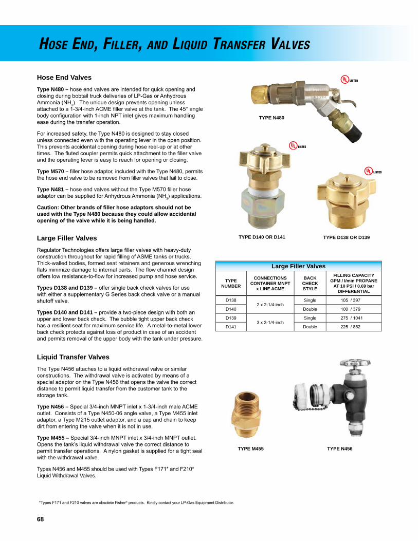
68
Hose End ValvesType N480 – hose end valves are intended for quick opening and closing during bobtail truck deliveries of lP-Gas or Anhydrous Ammonia (NH3). The unique design prevents opening unless attached to a 1-3/4-inch ACMe fi ller valve at the tank. The 45° angle body confi guration with 1-inch NPT inlet gives maximum handling ease during the transfer operation.
For increased safety, the Type N480 is designed to stay closed unless connected even with the operating lever in the open position. This prevents accidental opening during hose reel-up or at other times. The fl uted coupler permits quick attachment to the fi ller valve and the operating lever is easy to reach for opening or closing.
Type M570 – fi ller hose adaptor, included with the Type N480, permits the hose end valve to be removed from fi ller valves that fail to close.
Type N481 – hose end valves without the Type M570 fi ller hose adaptor can be supplied for Anhydrous Ammonia (NH3) applications.
Caution: Other brands of fi ller hose adaptors should not be used with the Type N480 because they could allow accidental opening of the valve while it is being handled.
Large Filler ValvesRegulator Technologies offers large fi ller valves with heavy-duty construction throughout for rapid fi lling of ASMe tanks or trucks. Thick-walled bodies, formed seat retainers and generous wrenching fl ats minimize damage to internal parts. The fl ow channel design offers low resistance-to-fl ow for increased pump and hose service.
Types D138 and D139 – offer single back check valves for use with either a supplementary G Series back check valve or a manual shutoff valve.
Types D140 and D141 – provide a two-piece design with both an upper and lower back check. The bubble tight upper back check has a resilient seat for maximum service life. A metal-to-metal lower back check protects against loss of product in case of an accident and permits removal of the upper body with the tank under pressure.
Liquid Transfer ValvesThe Type N456 attaches to a liquid withdrawal valve or similar constructions. The withdrawal valve is activated by means of a special adaptor on the Type N456 that opens the valve the correct distance to permit liquid transfer from the customer tank to the storage tank.
Type N456 – Special 3/4-inch MNPT inlet x 1-3/4-inch male ACMe outlet. Consists of a Type N450-06 angle valve, a Type M455 inlet adaptor, a Type M215 outlet adaptor, and a cap and chain to keep dirt from entering the valve when it is not in use.
Type M455 – Special 3/4-inch MNPT inlet x 3/4-inch MNPT outlet. Opens the tank’s liquid withdrawal valve the correct distance to permit transfer operations. A nylon gasket is supplied for a tight seal with the withdrawal valve.
Types N456 and M455 should be used with Types F171* and F210* liquid Withdrawal Valves.
HOSE END, FILLER, AND LIQUID TRANSFER VALVES
Large Filler Valves
TYPENUMBER
CONNECTIONSCONTAINER MNPT
x LINE ACME
BACKCHECKSTYLE
FILLING CAPACITYGPM / l/min PROPANE
AT 10 PSI / 0,69 bar DIFFERENTIAL
d1382 x 2-1/4-inch
Single 105 / 397
d140 double 100 / 379
d1393 x 3-1/4-inch
Single 275 / 1041
D141 double 225 / 852
TYPE N480
TYPE D140 OR D141 TYPE D138 OR D139
TYPE M455 TYPE N456
*Types F171 and F210 valves are obsolete Fisher® products. Kindly contact your lP-Gas equipment distributor.
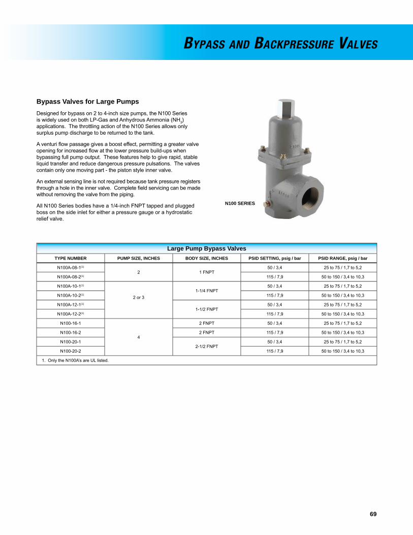
69
Bypass Valves for Large Pumpsdesigned for bypass on 2 to 4-inch size pumps, the N100 Series is widely used on both lP-Gas and Anhydrous Ammonia (NH3)applications. The throttling action of the N100 Series allows only surplus pump discharge to be returned to the tank.
A venturi fl ow passage gives a boost effect, permitting a greater valve opening for increased fl ow at the lower pressure build-ups when bypassing full pump output. These features help to give rapid, stable liquid transfer and reduce dangerous pressure pulsations. The valves contain only one moving part - the piston style inner valve.
An external sensing line is not required because tank pressure registers through a hole in the inner valve. Complete fi eld servicing can be made without removing the valve from the piping.
All N100 Series bodies have a 1/4-inch FNPT tapped and plugged boss on the side inlet for either a pressure gauge or a hydrostatic relief valve.
Large Pump Bypass ValvesTYPE NUMBER PUMP SIZE, INCHES BODY SIZE, INCHES PSID SETTING, psig / bar PSID RANGE, psig / bar
N100A-08-1(1)
2 1 FNPT50 / 3,4 25 to 75 / 1,7 to 5,2
N100A-08-2(1) 115 / 7,9 50 to 150 / 3,4 to 10,3
N100A-10-1(1)
2 or 3 1-1/4 FNPT
50 / 3,4 25 to 75 / 1,7 to 5,2
N100A-10-2(1) 115 / 7,9 50 to 150 / 3,4 to 10,3
N100A-12-1(1)
1-1/2 FNPT50 / 3,4 25 to 75 / 1,7 to 5,2
N100A-12-2(1) 115 / 7,9 50 to 150 / 3,4 to 10,3
N100-16-1
4
2 FNPT 50 / 3,4 25 to 75 / 1,7 to 5,2
N100-16-2 2 FNPT 115 / 7,9 50 to 150 / 3,4 to 10,3
N100-20-12-1/2 FNPT
50 / 3,4 25 to 75 / 1,7 to 5,2
N100-20-2 115 / 7,9 50 to 150 / 3,4 to 10,3
1. Only the N100A’s are Ul listed.
BYPASS AND BACKPRESSURE VALVES
N100 SERIES
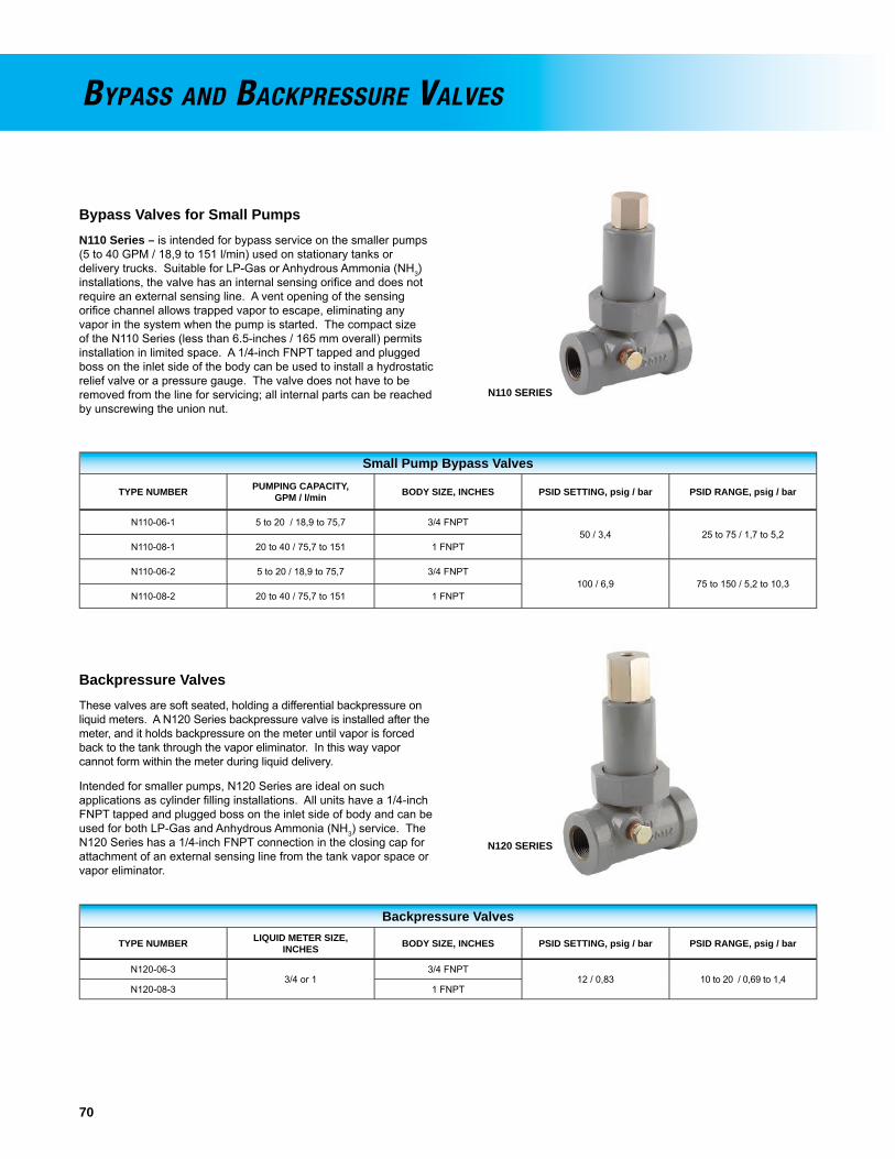
70
Bypass Valves for Small PumpsN110 Series – is intended for bypass service on the smaller pumps (5 to 40 GPM / 18,9 to 151 l/min) used on stationary tanks or delivery trucks. Suitable for lP-Gas or Anhydrous Ammonia (NH3)installations, the valve has an internal sensing orifi ce and does not require an external sensing line. A vent opening of the sensing orifi ce channel allows trapped vapor to escape, eliminating any vapor in the system when the pump is started. The compact size of the N110 Series (less than 6.5-inches / 165 mm overall) permits installation in limited space. A 1/4-inch FNPT tapped and plugged boss on the inlet side of the body can be used to install a hydrostatic relief valve or a pressure gauge. The valve does not have to be removed from the line for servicing; all internal parts can be reached by unscrewing the union nut.
Small Pump Bypass Valves
TYPE NUMBER PUMPING CAPACITY,GPM / l/min BODY SIZE, INCHES PSID SETTING, psig / bar PSID RANGE, psig / bar
N110-06-1 5 to 20 / 18,9 to 75,7 3/4 FNPT50 / 3,4 25 to 75 / 1,7 to 5,2
N110-08-1 20 to 40 / 75,7 to 151 1 FNPT
N110-06-2 5 to 20 / 18,9 to 75,7 3/4 FNPT100 / 6,9 75 to 150 / 5,2 to 10,3
N110-08-2 20 to 40 / 75,7 to 151 1 FNPT
Backpressure ValvesThese valves are soft seated, holding a differential backpressure on liquid meters. A N120 Series backpressure valve is installed after the meter, and it holds backpressure on the meter until vapor is forced back to the tank through the vapor eliminator. In this way vapor cannot form within the meter during liquid delivery.
Intended for smaller pumps, N120 Series are ideal on such applications as cylinder fi lling installations. All units have a 1/4-inch FNPT tapped and plugged boss on the inlet side of body and can be used for both lP-Gas and Anhydrous Ammonia (NH3) service. The N120 Series has a 1/4-inch FNPT connection in the closing cap for attachment of an external sensing line from the tank vapor space or vapor eliminator.
Backpressure Valves
TYPE NUMBER LIQUID METER SIZE,INCHES BODY SIZE, INCHES PSID SETTING, psig / bar PSID RANGE, psig / bar
N120-06-33/4 or 1
3/4 FNPT12 / 0,83 10 to 20 / 0,69 to 1,4
N120-08-3 1 FNPT
BYPASS AND BACKPRESSURE VALVES
N110 SERIES
N120 SERIES

71
Rotary GaugesFisher® brand rotary gauges can be used on stationary or mobile tanks to visually indicate the amount of LP-Gas or Anhydrous Ammonia (NH3) in the container. They are also used in fi lling the tank to the proper liquid level. On mobile applications and some large stationary storage tanks, hangers are recommended to support the horizontal length of the dip tube.
The gauge is operated by opening the small bleed orifi ce when the tube is in the vapor space of the tank. Moving the pointer on the dial causes the end of the tube to move until it contacts liquid in the container. At that point, discharge from the bleed orifi ce turns from vapor to liquid and the rotary gauge dial gives the volume percentage of liquid in the tank.
J31 Series – consists of heavy duty gauges that minimize vibration effects (swaying, bouncing) by a long (68-inches / 1,73 meters) stem tube extension. Gauges fi t 1-inch / 25,4 mm coupling container connections.
All gauges have stem and dip tubes with an extra large inside diameter. This assures that the correct liquid level can be obtained quickly.
A nylon packing sleeve and a friction ring for the pointer indicator gives smooth rotation and long service life. Steel and stainless steel materials resist rust or corrosion.
Rotary Gauges
LENGTH,INCHES / mm
LPG DIAL>1200
GALLON
LPG DIAL≤1200
GALLON
NH3 DIAL>1200
GALLON
NO DIAL>1200
GALLON
68/ 1727 Type J31L-1 Type J31S-1 Type J31A-1 Type J31X-1
69 to 92/ 1753 to 2337 Type J31L-2 Type J31S-2 Type J31A-2 Type J31X-2
93 to 108/ 2362 to 2743 Type J31L-3 Type J31S-3 Type J31A-3 Type J31X-3
109 to 140/ 2769 to 3556 Type J31L-3L Type J31S-3L Type J31A-3L Type J31X-3L
Dial Only Type P323 Type P322 Type P324 - - - -
Liquid Level Vent ValvesType J415 – with steel construction, can be used on either LP-Gas or Anhydrous Ammonia (NH3) service. They can also be installed on large bulk storage tanks at the maximum fi lling level. Standard valve comes with a 3/4-inch MNPT container connection and two 1/4-inch FNPT side outlets.
Type J415-1 – features the addition of a Type J402S liquid level vent valve and Type J542 (0 to 400 psig / 0 to 27,6 bar) pressure gauge installed.
Vent Valves and Fixed Maximum Liquid Level GaugesUsed in all kinds of LP-Gas containers to give positive visual indication of liquid reaching the maximum allowable liquid level.
Types J402S and J403S do not have dip tubes and must be used in containers where a dip tube has been welded in. Stainless steel constructions are for corrosive service.
Container ThermometersSuitable for any size tank in LP-Gas and NH3 service, the 2-inch / 51 mm diameter dial reads from -40° to 120°F / -40° to 49°C. They are dustproof and waterproof. Specify J700 Series for a 1/2-inch MNPT by a 4 inches / 102 mm length or Type J701 for a 1/2-inch MNPT by 6 inches / 152 mm length.
LIQUID LEVEL INDICATORS
J31 SERIES TYPE J415TYPE J415-1
TYPE J402S TYPE J403S
J700 SERIES ORTYPE J701

72
Female ACME Filler CouplingsFEMALEACME,INCHES
OTHERCONNECTION,
INCHES
LENGTH,INCHES / mm
TYPE NUMBER
Brass Steel
1-3/4
1/2 MNPT 3 / 76 1 M110 - - - -
3/4 MNPT3 / 76 1 M111 M631-6
6-1/8 / 156 2 - - - - M635-6
1 MNPT3 / 76 1 M112 M631-8
7 / 178 2 - - - - M635-82-1/4 1-1/4 MNPT 3-1/4 / 83 3 M120(1) M121
3-1/41-1/4 FNPT 1-1/2 / 38 4 M442 - - - -
2 MNPT 3-3/4 / 95 3 M130(1) M1334-1/4 3 MNPT 4-1/2 / 114 3 M664-24 M634-24
1. Steel Nipple
Female ACME Vapor Return CouplingsFEMALE
ACME, INCHESMALE NPT,
INCHESLENGTH,
INCHES / mm
TYPE NUMBER
Brass
1-3/43/4 7 / 178 6 - - - -
13-1/4 / 83 5 M151
7-3/8 / 187 6 - - - -2-1/4 1-1/4 3-3/8 / 86 7 M160
Male ACME AdaptorsMALE ACME,
INCHESTYPE NUMBER WASHER
DRAWING NUMBERBrass Steel Ductile Iron
1-1/4 x 1-1/4 M270 - - - - - - - - 1E81221-3/4 x 1-3/4 M273 M536-14 - - - - 1E81242-1/4 x 2-1/4 - - - - M536-18 - - - - 1E81263-1/4 x 3-1/4 - - - - M536-26 - - - - 1E81284-1/4 x 4-1/4 - - - - - - - - M536-34 T10948
Male ACME x Female NPT AdaptorsMALEACME,
INCHES
FEMALENPT,
INCHES
TYPE NUMBER WASHERDRAWINGNUMBERBrass Steel
1-3/4
1/4 8 M210 - - - -
1E81241/2 8 M212 - - - -3/4 8 M213 M526-61 8 M214 M526-8
2-1/41 9 M502-12/8 - - - -
1E81261-1/4 9 M502-16/10 M522-16/101-1/2 9 M502-16/12 - - - -
3-1/41-1/4 8 M250 - - - -
1E81282 8 M252 M528-163 8 M508-24 M528-24
4-1/4 3 8 M509-24 M529-24 T10948
COUPLINGS AND ADAPTORS
TYPE M270
Female ACME Vapor Return CouplingsVapor return couplings are available with 1-1/4 through 2-1/4-inch female ACME threads on one side and 3/8 through 1-1/4-inch male NPT threads on the other. Brass or steel construction.
Female ACME Filler CouplingsThese couplings allow connection of ACME threads to NPT. One side is 1-1/4 through 4-1/4-inch female ACME. The other side is 3/8 through 3-inch NPT. Available in brass or steel.
Male ACME by Female NPT AdaptorsThese adaptors provide 1-1/4 through 4-1/4-inch male ACME on one side and 1/4 through 3/4-inch female NPT threads on the other side. Brass or steel construction.
Male ACME AdaptorsThese adaptors are male ACME to male ACME in sizes 1-1/4 by 1-1/4-inch through 4-1/4 by 4-1/4-inch. Brass or steel construction.
1 2 3 4
5 6 7
8 9
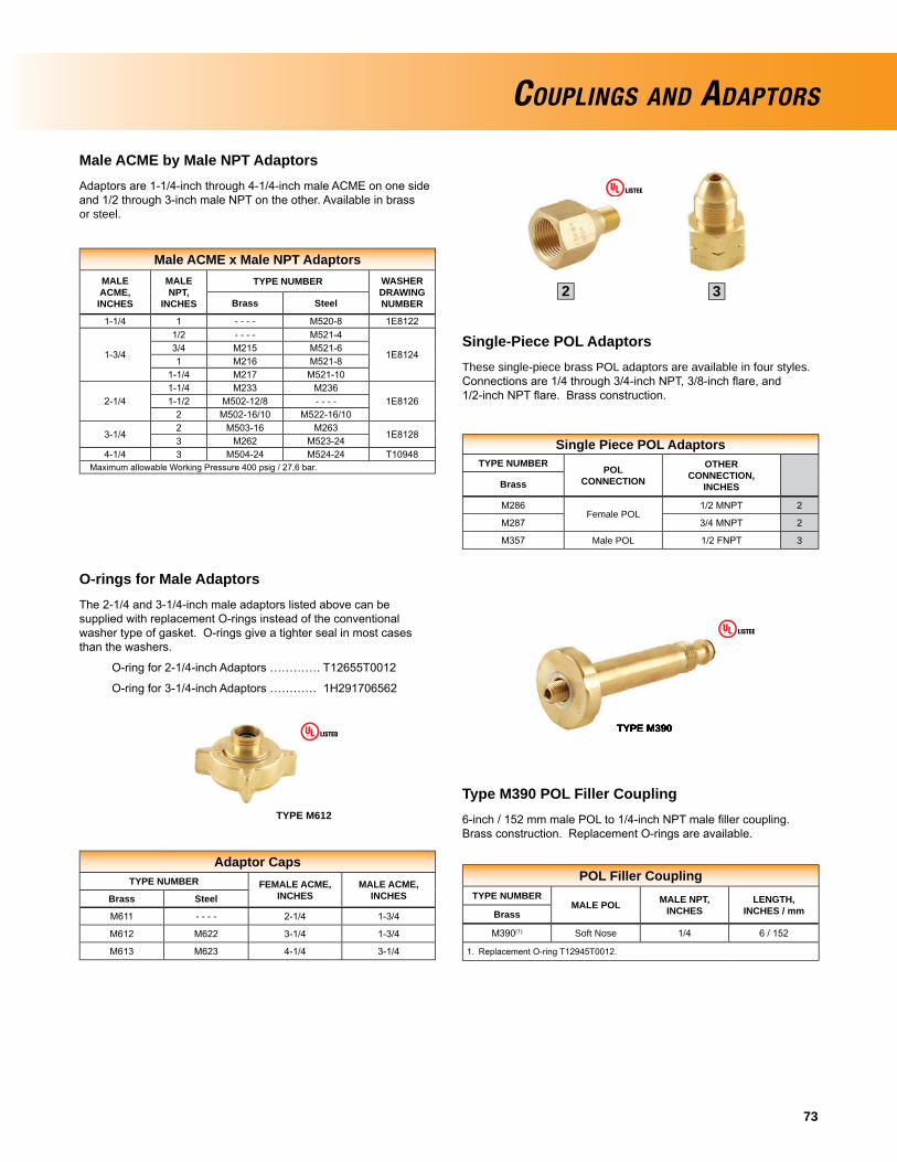
73
Male ACME x Male NPT AdaptorsMALEACME,INCHES
MALENPT,
INCHES
TYPE NUMBER WASHERDRAWINGNUMBERBrass Steel
1-1/4 1 - - - - M520-8 1E8122
1-3/4
1/2 - - - - M521-4
1E81243/4 M215 M521-61 M216 M521-8
1-1/4 M217 M521-10
2-1/41-1/4 M233 M236
1E81261-1/2 M502-12/8 - - - -2 M502-16/10 M522-16/10
3-1/42 M503-16 M263
1E81283 M262 M523-24
4-1/4 3 M504-24 M524-24 T10948 Maximum allowable Working Pressure 400 psig / 27,6 bar.
Single Piece POL AdaptorsTYPE NUMBER POL
CONNECTION
OTHERCONNECTION,
INCHESBrass
M286Female POL
1/2 MNPT 2
M287 3/4 MNPT 2
M357 Male POL 1/2 FNPT 3
COUPLINGS AND ADAPTORS
Male ACME by Male NPT AdaptorsAdaptors are 1-1/4-inch through 4-1/4-inch male ACME on one side and 1/2 through 3-inch male NPT on the other. Available in brass or steel.
Single-Piece POL AdaptorsThese single-piece brass POL adaptors are available in four styles. Connections are 1/4 through 3/4-inch NPT, 3/8-inch fl are, and 1/2-inch NPT fl are. Brass construction.
Adaptor CapsTYPE NUMBER FEMALE ACME,
INCHESMALE ACME,
INCHESBrass Steel
M611 - - - - 2-1/4 1-3/4
M612 M622 3-1/4 1-3/4
M613 M623 4-1/4 3-1/4
O-rings for Male AdaptorsThe 2-1/4 and 3-1/4-inch male adaptors listed above can be supplied with replacement O-rings instead of the conventional washer type of gasket. O-rings give a tighter seal in most cases than the washers.
O-ring for 2-1/4-inch Adaptors …………. T12655T0012
O-ring for 3-1/4-inch Adaptors ………… 1H291706562
TYPE M612
POL Filler CouplingTYPE NUMBER
MALE POL MALE NPT,INCHES
LENGTH,INCHES / mmBrass
M390(1) Soft Nose 1/4 6 / 152
1. Replacement O-ring T12945T0012.
TYPE M390
Type M390 POL Filler Coupling6-inch / 152 mm male POL to 1/4-inch NPT male fi ller coupling. Brass construction. Replacement O-rings are available.
TYPE M390
2 3

74
Seals and Plugs
DUST SEAL PLUG BODY SIZE,INCHES
Type M178 plastic - - - - 1-1/4 Male ACME
Type M179 plastic - - - - 1-3/4 Male ACME
Type M180 plastic - - - - 2-1/4 Male ACME
Type M181 plastic - - - - 3-1/4 Male ACME
- - - - Type M535-34 steel 4-1/4 Male ACME
Filler Hose AdaptorIntended for the outlet of a bobtail truck fi lling hose, the Type M570 enables the fi lling hose to be removed if the fi ller valve fails to close. An integral back check in the adaptor prevents gas from escaping in the event of a failure of the fi ller valve. The fi ller valve should be repaired as soon as possible and the Type M570 removed from the fi ller valve.
Filler Hose Adaptor
TYPE NUMBERFILLER VALVECONNECTION,
INCHES
HOSE END VALVECONNECTION,
INCHES
BODYMATERIAL
M570 1-3/4 Female ACME 1-3/4 Male ACME Brass
COUPLINGS AND ADAPTORS
TYPE M570
TYPE M178
Seals and Plugs
ACME plugs of various sizes and materials are used in female ACME threads to keep debris out of the piping systems.
Filler Valve AdaptorType M450A – allows methanol to be added through conventional designed double back check fi ller valves with a 1-3/4-inch male ACME fi ller connection and 3/4-inch FNPT outlet.
TYPE M450A
Relief Valve Pipeaway AdaptorPIPEAWAY ADAPTOR STYLE TYPE NUMBER VALVE TYPE
P104-24H282
H5112
P174
H125
H150
H148
H173
Pipeaway AdaptorDOT cylinder relief valves must be installed with a pipeaway adaptor to ensure that any discharge is directed away to a safe location.
TYPE P104-24
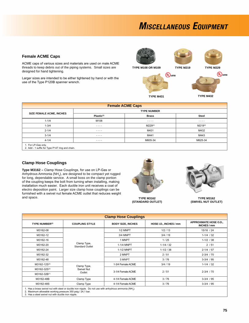
75
Female ACME Caps
SIZE FEMALE ACME, INCHESTYPE NUMBER
Plastic(1) Brass Steel
1-1/4 M108 - - - - - - - -
1-3/4 - - - - M229(2) M219(2)
2-1/4 - - - - M431 M432
3-1/4 - - - - M441 M443
4-1/4 - - - - M605-34 M625-34
1. For LP-Gas only. 2. Add - 1 suffi x for Type P147 ring and chain.
Clamp Hose CouplingsType M3162 – Clamp Hose Couplings, for use on LP-Gas or Anhydrous Ammonia (NH3), are designed to be compact yet rugged for long, dependable service. A small boss on the clamp portion of the coupling keeps the bolt from turning when installing, making installation much easier. Each ductile iron unit receives a coat of electro deposition paint. Larger size clamp hose couplings can be furnished with a swivel nut female ACME outlet that reduces weight and space.
Clamp Hose Couplings
TYPE NUMBER(2) COUPLING STYLE BODY SIZE, INCHES HOSE I.D., INCHES / mm APPROXIMATE HOSE O.D.,INCHES / mm
M3162-08
Clamp Type,Standard Outlet
1/2 MNPT 1/2 / 13 15/16 / 24
M3162-12 3/4 MNPT 3/4 / 19 1-1/4 / 32
M3162-16 1 MNPT 1 / 25 1-1/2 / 38
M3162-20 1-1/4 MNPT 1-1/4 / 32 2 / 51
M3162-24 1-1/2 MNPT 1-1/2 / 38 2-1/4 / 57
M3162-32 2 MNPT 2 / 51 2-3/4 / 70
M3162-48 3 MNPT 3 / 76 3-3/4 / 95
M3162-12S(3)Clamp Type,Swivel Nut
Outlet
1-3/4 Female ACME 3/4 / 19 1-1/4 / 32
M3162-32S(3)
3-1/4 Female ACME 2 / 51 2-3/4 / 70M3162-32B(1)
M3162-48B Clamp Type 4-1/4 Female ACME 3 / 76 3-3/4 / 95
M3162-48S Clamp Type 4-1/4 Female ACME 3 / 76 3-3/4 / 95
1. Has a brass swivel nut with steel or ductile iron nipple. Do not use with anhydrous ammonia (NH3). 2. Maximum allowable working pressure 350 psig / 24,1 bar. 3. Has a steel swivel nut with ductile iron nipple.
MISCELLANEOUS EQUIPMENT
TYPE M108 OR M109 TYPE M219 TYPE M229
TYPE M431 TYPE M432
TYPE M3162 (STANDARD OUTLET)
TYPE M3162 (SWIVEL NUT OUTLET)
Female ACME CapsACME caps of various sizes and materials are used on male ACME threads to keep debris out of the piping systems. Small sizes are designed for hand tightening.
Larger sizes are intended to be either tightened by hand or with the use of the Type P120B spanner wrench.
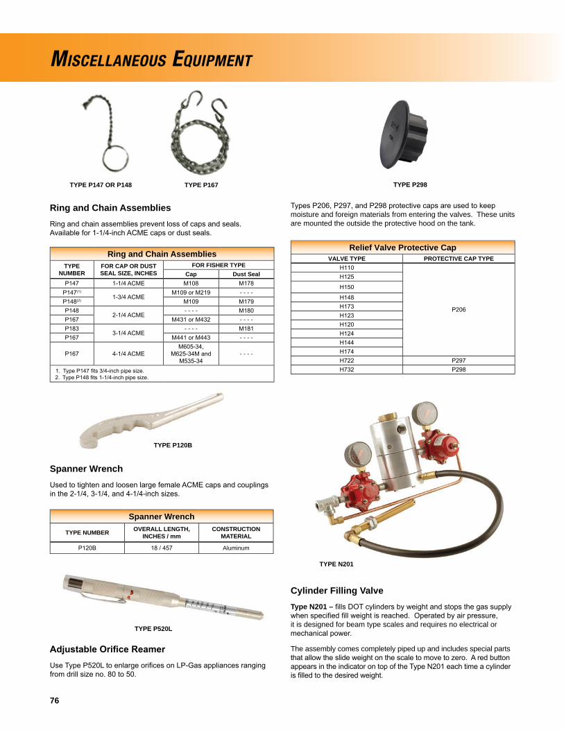
76
MISCELLANEOUS EQUIPMENT
Ring and Chain AssembliesTYPE
NUMBERFOR CAP OR DUST SEAL SIZE, INCHES
FOR FISHER TYPECap Dust Seal
P147 1-1/4 ACME M108 M178P147(1)
1-3/4 ACMEM109 or M219 - - - -
P148(2) M109 M179P148
2-1/4 ACME- - - - M180
P167 M431 or M432 - - - -P183
3-1/4 ACME- - - - M181
P167 M441 or M443 - - - -
P167 4-1/4 ACMEM605-34,
M625-34M andM535-34
- - - -
1. Type P147 fi ts 3/4-inch pipe size. 2. Type P148 fi ts 1-1/4-inch pipe size.
Spanner WrenchUsed to tighten and loosen large female ACME caps and couplings in the 2-1/4, 3-1/4, and 4-1/4-inch sizes.
Spanner Wrench
TYPE NUMBER OVERALL LENGTH,INCHES / mm
CONSTRUCTIONMATERIAL
P120B 18 / 457 Aluminum
Adjustable Orifi ce ReamerUse Type P520L to enlarge orifi ces on LP-Gas appliances ranging from drill size no. 80 to 50.
TYPE P120B
TYPE P520L
TYPE P167TYPE P147 OR P148
Ring and Chain AssembliesRing and chain assemblies prevent loss of caps and seals. Available for 1-1/4-inch ACME caps or dust seals.
Relief Valve Protective CapVALVE TYPE PROTECTIVE CAP TYPE
H110
P206
H125
H150
H148H173H123H120H124H144H174H722 P297H732 P298
TYPE P298
Types P206, P297, and P298 protective caps are used to keep moisture and foreign materials from entering the valves. These units are mounted the outside the protective hood on the tank.
Cylinder Filling ValveType N201 – fi lls DOT cylinders by weight and stops the gas supply when specifi ed fi ll weight is reached. Operated by air pressure, it is designed for beam type scales and requires no electrical or mechanical power.
The assembly comes completely piped up and includes special parts that allow the slide weight on the scale to move to zero. A red button appears in the indicator on top of the Type N201 each time a cylinder is fi lled to the desired weight.
TYPE N201

77 77

78
Expanding your knowledge of LP-Gas is quick and easy with absolutely no obligation and no cost to you.
1. Decide which LP-Gas bulletin(s) you would like.
2. Contact your local LP-Gas Regulators and Equipment Distributor to order.
Bulletin LP-10 (D450116T012): LP-Gas Serviceman’s Handbook:Popularfactfilled48-pagebookletincludesdataonregulatorselection, tank and cylinder location, pipe and tubing sizing, and much more.
Bulletin LP-12 (D450139T012): Regulator Chart. Handy reference guide for selecting Fisher regulators with convenient method of sizing pipe and tubing on the reverse side.
Bulletin LP-15 (D450144T012): Give A Regulator the Attention it Deserves. Explains how domestic direct-operated regulators work, gives installation and maintenance tips.
Bulletin LP-18 (D450145T012): How Drip Lips Can Prevent Regulator Freeze-Ups. Shows how drip-lip style vents can reduce the possibility of vent blockage due to freezing rain or sleet.
Bulletin LP-19 (D450061T012): Keeping Your Internal Valves Working. A thorough discussion about the operation, installation, maintenance, and trouble shooting procedures for Fisher internal valves.
Bulletin LP-24 (D450146T012): Plain Facts About Freezing Regulators. Describes how a regulator can freeze internally and tells ways to minimize freeze-up problems.
Bulletin LP-29 (D450143T012): Complying With NFPA 58 Transfer Area Rulings. Discusses how valves and accessory equipment can be used to satisfy NFPA 58 requirements regarding the transfer area at LP-Gas bulk plants.
Bulletin LP-32 (D450142T012): Inspecting LP-Gas Regulators: What to Look For. Discusses service life of a regulator, how to reduce chance of vent blockage, ways to inspect for internal corrosion.
LP-12 Regulator Chart gives a quick selection guide for LP-Gas regulators and pipe and tubing sizes.
LP-31 Catalog offers the most up-to-date LP product line and serves as a guide to the various Fisher Product that is appropriate for your LP application needs.
LP-10 Bulletin is the LP-Gas Serviceman’s handbook that provides sizing and installation instructions in accordance with standard codes and regulations.
LP Application Guide provides application and product data for the different LP products including detailed information on their specifi cations and capacities.
Remember, Regulator Technologies also provides literature in quantity forinstructional purposes for industry association schools, state
association schools, and dealer schools.Visit our web site at www.fi sherregulators.com or call
+1 800 558 5853 for anAuthorized LP-Gas Regulator and Equipment Distributor near you.
LITERATURE
Literature From Fisher®
The Next Best Thing To An LP-Gas Encyclopedia.
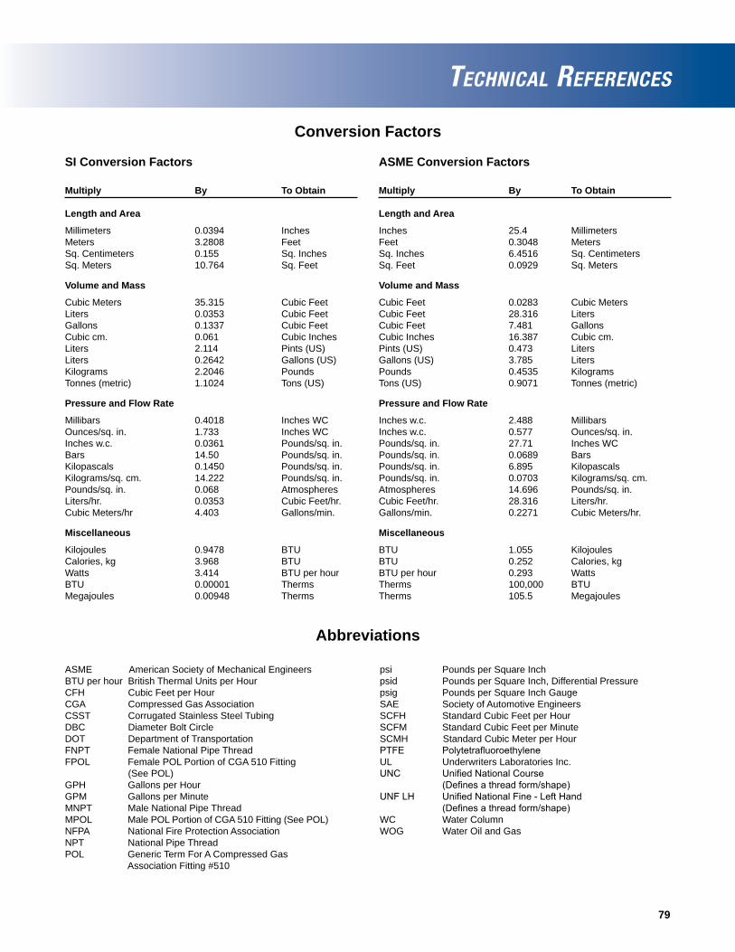
79
SI Conversion Factors
Multiply By To Obtain
Length and Area
Millimeters 0.0394 InchesMeters 3.2808 FeetSq. Centimeters 0.155 Sq. InchesSq. Meters 10.764 Sq. Feet
Volume and Mass
Cubic Meters 35.315 Cubic FeetLiters 0.0353 Cubic FeetGallons 0.1337 Cubic FeetCubic cm. 0.061 Cubic InchesLiters 2.114 Pints (US)Liters 0.2642 Gallons (US)Kilograms 2.2046 PoundsTonnes (metric) 1.1024 Tons (US)
Pressure and Flow Rate
Millibars 0.4018 Inches WCOunces/sq. in. 1.733 Inches WCInches w.c. 0.0361 Pounds/sq. in.Bars 14.50 Pounds/sq. in.Kilopascals 0.1450 Pounds/sq. in.Kilograms/sq. cm. 14.222 Pounds/sq. in.Pounds/sq. in. 0.068 AtmospheresLiters/hr. 0.0353 Cubic Feet/hr.Cubic Meters/hr 4.403 Gallons/min.
Miscellaneous
Kilojoules 0.9478 BTUCalories, kg 3.968 BTUWatts 3.414 BTU per hourBTU 0.00001 ThermsMegajoules 0.00948 Therms
Conversion Factors
ASME Conversion Factors
Multiply By To Obtain
Length and Area
Inches 25.4 MillimetersFeet 0.3048 MetersSq. Inches 6.4516 Sq. CentimetersSq. Feet 0.0929 Sq. Meters
Volume and Mass
Cubic Feet 0.0283 Cubic MetersCubic Feet 28.316 LitersCubic Feet 7.481 GallonsCubic Inches 16.387 Cubic cm.Pints (US) 0.473 LitersGallons (US) 3.785 LitersPounds 0.4535 KilogramsTons (US) 0.9071 Tonnes (metric)
Pressure and Flow Rate
Inches w.c. 2.488 MillibarsInches w.c. 0.577 Ounces/sq. in.Pounds/sq. in. 27.71 Inches WCPounds/sq. in. 0.0689 BarsPounds/sq. in. 6.895 KilopascalsPounds/sq. in. 0.0703 Kilograms/sq. cm.Atmospheres 14.696 Pounds/sq. in.Cubic Feet/hr. 28.316 Liters/hr.Gallons/min. 0.2271 Cubic Meters/hr.
Miscellaneous
BTU 1.055 KilojoulesBTU 0.252 Calories, kgBTU per hour 0.293 WattsTherms 100,000 BTUTherms 105.5 Megajoules
Abbreviations
ASME American Society of Mechanical EngineersBTU per hour British Thermal Units per HourCFH Cubic Feet per HourCGA Compressed Gas AssociationCSST Corrugated Stainless Steel TubingDBC Diameter Bolt CircleDOT Department of TransportationFNPT Female National Pipe ThreadFPOL Female POL Portion of CGA 510 Fitting (See POL)GPH Gallons per HourGPM Gallons per MinuteMNPT Male National Pipe ThreadMPOL Male POL Portion of CGA 510 Fitting (See POL)NFPA National Fire Protection AssociationNPT National Pipe ThreadPOL Generic Term For A Compressed Gas Association Fitting #510
psi Pounds per Square Inchpsid Pounds per Square Inch, Differential Pressurepsig Pounds per Square Inch GaugeSAE Society of Automotive EngineersSCFH Standard Cubic Feet per HourSCFM Standard Cubic Feet per MinuteSCMH Standard Cubic Meter per HourPTFE PolytetrafluoroethyleneUL Underwriters Laboratories Inc.UNC UnifiedNationalCourse (Definesathreadform/shape)UNFLH UnifiedNationalFine-LeftHand (Definesathreadform/shape)WC Water ColumnWOG Water Oil and Gas
TECHNICAL REFERENCES
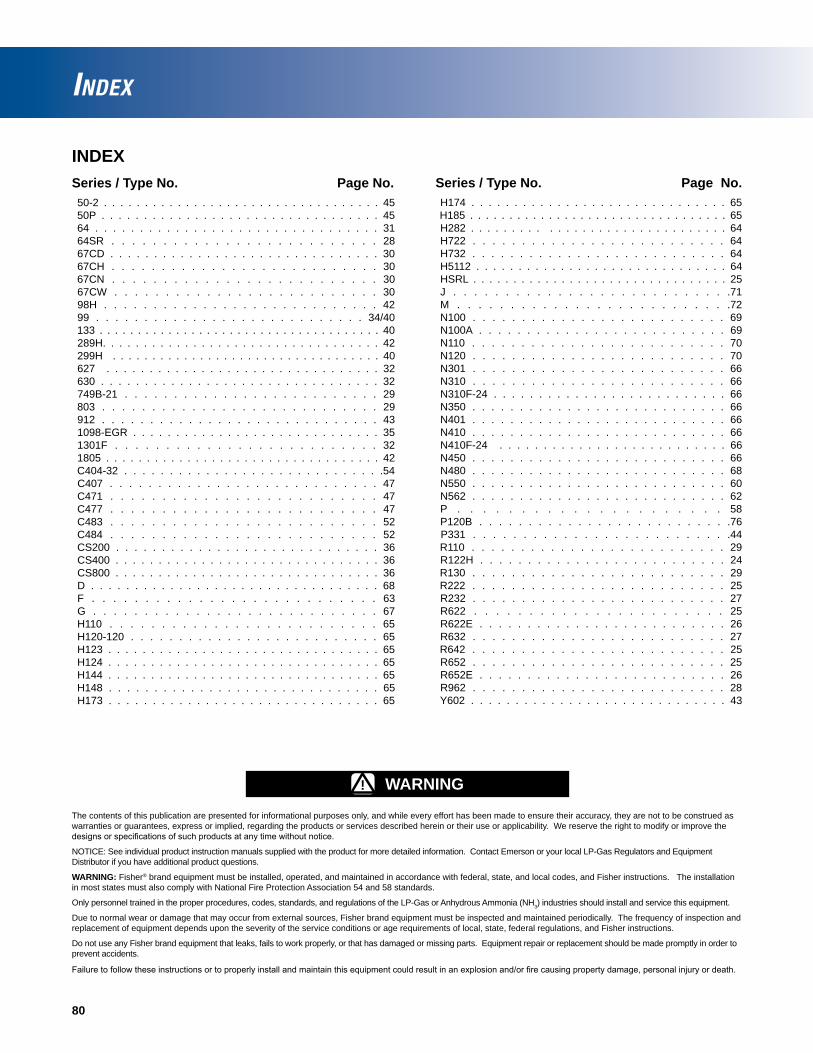
80
INDEXSeries / Type No. Page No. 50-2 . . . . . . . . . . . . . . . . . . . . . . . . . . . . . . . . . . 45 50P . . . . . . . . . . . . . . . . . . . . . . . . . . . . . . . . . 45 64 . . . . . . . . . . . . . . . . . . . . . . . . . . . . . . . . 31 64SR . . . . . . . . . . . . . . . . . . . . . . . . . . 28 67CD . . . . . . . . . . . . . . . . . . . . . . . . . . . . . . . 30 67CH . . . . . . . . . . . . . . . . . . . . . . . . . . . 30 67CN . . . . . . . . . . . . . . . . . . . . . . . . . . 30 67CW . . . . . . . . . . . . . . . . . . . . . . . . . . 30 98H . . . . . . . . . . . . . . . . . . . . . . . . . . . . 42 99 . . . . . . . . . . . . . . . . . . . . . . . . . . . . 34/40 133 . . . . . . . . . . . . . . . . . . . . . . . . . . . . . . . . . . . . . 40 289H. . . . . . . . . . . . . . . . . . . . . . . . . . . . . . . . . . 42 299H . . . . . . . . . . . . . . . . . . . . . . . . . . . . . . . . . . 40 627 . . . . . . . . . . . . . . . . . . . . . . . . . . . . . . . . 32 630 . . . . . . . . . . . . . . . . . . . . . . . . . . . . . . . . 32 749B-21 . . . . . . . . . . . . . . . . . . . . . . . . . . 29 803 . . . . . . . . . . . . . . . . . . . . . . . . . . . . 29 912 . . . . . . . . . . . . . . . . . . . . . . . . . . . . . 43 1098-EGR . . . . . . . . . . . . . . . . . . . . . . . . . . . . . 35 1301F . . . . . . . . . . . . . . . . . . . . . . . . . . 32 1805 . . . . . . . . . . . . . . . . . . . . . . . . . . . . . . . . . . 42 C404-32 . . . . . . . . . . . . . . . . . . . . . . . . . . . . .54 C407 . . . . . . . . . . . . . . . . . . . . . . . . . . . . 47 C471 . . . . . . . . . . . . . . . . . . . . . . . . . . 47 C477 . . . . . . . . . . . . . . . . . . . . . . . . . . 47 C483 . . . . . . . . . . . . . . . . . . . . . . . . . . 52 C484 . . . . . . . . . . . . . . . . . . . . . . . . . . 52 CS200 . . . . . . . . . . . . . . . . . . . . . . . . . . . . . 36 CS400 . . . . . . . . . . . . . . . . . . . . . . . . . . . . . . . 36 CS800 . . . . . . . . . . . . . . . . . . . . . . . . . . . . . . . 36 D . . . . . . . . . . . . . . . . . . . . . . . . . . . . . . . . . 68 F . . . . . . . . . . . . . . . . . . . . . . . . . . . 63 G . . . . . . . . . . . . . . . . . . . . . . . . . . . . 67 H110 . . . . . . . . . . . . . . . . . . . . . . . . . . 65 H120-120 . . . . . . . . . . . . . . . . . . . . . . . . . . 65 H123 . . . . . . . . . . . . . . . . . . . . . . . . . . . . . . . . 65 H124 . . . . . . . . . . . . . . . . . . . . . . . . . . . . . . . . 65 H144 . . . . . . . . . . . . . . . . . . . . . . . . . . . . . . . . 65 H148 . . . . . . . . . . . . . . . . . . . . . . . . . . . . . . 65 H173 . . . . . . . . . . . . . . . . . . . . . . . . . . . . . . . 65
Series / Type No. Page No.H174 . . . . . . . . . . . . . . . . . . . . . . . . . . . . . . 65
H185 . . . . . . . . . . . . . . . . . . . . . . . . . . . . . . . . . 65H282 . . . . . . . . . . . . . . . . . . . . . . . . . . . . . . . 64H722 . . . . . . . . . . . . . . . . . . . . . . . . . . 64H732 . . . . . . . . . . . . . . . . . . . . . . . . . . . 64H5112 . . . . . . . . . . . . . . . . . . . . . . . . . . . . . . 64HSRL . . . . . . . . . . . . . . . . . . . . . . . . . . . . . . . . 25J . . . . . . . . . . . . . . . . . . . . . . . . . . .71M . . . . . . . . . . . . . . . . . . . . . . . . . .72N100 . . . . . . . . . . . . . . . . . . . . . . . . . . 69N100A . . . . . . . . . . . . . . . . . . . . . . . . . . 69N110 . . . . . . . . . . . . . . . . . . . . . . . . . . 70N120 . . . . . . . . . . . . . . . . . . . . . . . . . . 70N301 . . . . . . . . . . . . . . . . . . . . . . . . . . 66N310 . . . . . . . . . . . . . . . . . . . . . . . . . . 66N310F-24 . . . . . . . . . . . . . . . . . . . . . . . . . . 66N350 . . . . . . . . . . . . . . . . . . . . . . . . . . . 66N401 . . . . . . . . . . . . . . . . . . . . . . . . . . . 66N410 . . . . . . . . . . . . . . . . . . . . . . . . . . . 66N410F-24 . . . . . . . . . . . . . . . . . . . . . . . . . . 66N450 . . . . . . . . . . . . . . . . . . . . . . . . . . . 66N480 . . . . . . . . . . . . . . . . . . . . . . . . . . . 68N550 . . . . . . . . . . . . . . . . . . . . . . . . . . . 60N562 . . . . . . . . . . . . . . . . . . . . . . . . . . . 62P . . . . . . . . . . . . . . . . . . . . . 58P120B . . . . . . . . . . . . . . . . . . . . . . . . . .76
P331 . . . . . . . . . . . . . . . . . . . . . . . . . .44 R110 . . . . . . . . . . . . . . . . . . . . . . . . . . 29
R122H . . . . . . . . . . . . . . . . . . . . . . . . . . 24 R130 . . . . . . . . . . . . . . . . . . . . . . . . . . 29 R222 . . . . . . . . . . . . . . . . . . . . . . . . . . 25
R232 . . . . . . . . . . . . . . . . . . . . . . . . . . 27R622 . . . . . . . . . . . . . . . . . . . . . . . 25R622E . . . . . . . . . . . . . . . . . . . . . . . . . . 26R632 . . . . . . . . . . . . . . . . . . . . . . . . . . 27
R642 . . . . . . . . . . . . . . . . . . . . . . . . . . 25R652 . . . . . . . . . . . . . . . . . . . . . . . . . . 25R652E . . . . . . . . . . . . . . . . . . . . . . . . . . 26R962 . . . . . . . . . . . . . . . . . . . . . . . . . . 28Y602 . . . . . . . . . . . . . . . . . . . . . . . . . . . . . 43
The contents of this publication are presented for informational purposes only, and while every effort has been made to ensure their accuracy, they are not to be construed as warranties or guarantees, express or implied, regarding the products or services described herein or their use or applicability. We reserve the right to modify or improve the designsorspecificationsofsuchproductsatanytimewithoutnotice.
NOTICE: See individual product instruction manuals supplied with the product for more detailed information. Contact Emerson or your local LP-Gas Regulators and Equipment Distributor if you have additional product questions.
WARNING: Fisher® brand equipment must be installed, operated, and maintained in accordance with federal, state, and local codes, and Fisher instructions. The installation in most states must also comply with National Fire Protection Association 54 and 58 standards.
Only personnel trained in the proper procedures, codes, standards, and regulations of the LP-Gas or Anhydrous Ammonia (NH3) industries should install and service this equipment.
Due to normal wear or damage that may occur from external sources, Fisher brand equipment must be inspected and maintained periodically. The frequency of inspection and replacement of equipment depends upon the severity of the service conditions or age requirements of local, state, federal regulations, and Fisher instructions.
Do not use any Fisher brand equipment that leaks, fails to work properly, or that has damaged or missing parts. Equipment repair or replacement should be made promptly in order to prevent accidents.
Failuretofollowtheseinstructionsortoproperlyinstallandmaintainthisequipmentcouldresultinanexplosionand/orfirecausingpropertydamage,personalinjuryordeath.
INDEX
! WARNING

INTERNATIONAL DISTRIBUTOR MAP
United States
Mexico
Outside U.S.Europe
Asia
Anywhere in the world, Emerson resources are available by telephone or on our website. Our distribution network includes an experienced sales and support team, with more than 2,000 technical experts
available from nearly 200 offi ces throughout the world.
Please visit our website to fi nd the LP-Gas Equipment Distributor near you.
www.fisherregulators.com
LP-Gas Equipment DistributorsEmerson sales, service, and technical support are close at hand.
The World’s Leading Supplier of LP-Gas Equipment

D450104T012 © 2011 Emerson Process Management Regulator Technologies, Inc. All rights reserved. Printed in the U.S.A. 3/11. Fisher, Emerson Process Management, and the Emerson Process Management design are marks of one of the Emerson Process Management group of companies. All other marks are the property of their respective owners.
Emerson Process Management Regulator Technologies, Inc.
Americas Worldwide Headquarters310 East University DriveMcKinney, Texas 75069-1872 USAT: +1 800 558 5853T: +1 972 548 3574F: +1 972 542 6433
TESCOM Corporation12616 Industrial BoulevardElk River, Minnesota 55330-2445 USAT: +1 800 447 1250T: +1 763 241 3238F: +1 763 241 3224
Emerson Process ManagementRegulator Technologies, Inc.
Europe Natural Gas : T: +39 051 4190611Industrial: T: +39 051 4190606LP-Gas: T: +420 2 710 35 607TESCOM: T: +49 (0) 38823 31 0
Emerson Process ManagementRegulator Technologies, Inc.
Asia PacificT: +65 6770 8337
Middle EastT: +971 4811 8100
For further information visit www.fi sherregulators.com