Catalogo Commercial Serie 300
24
1 TM T M 300/400 Series Pumps and Motors Pressure to 3500 PSI Pumps with flows to over 90 GPM Motors with outputs to over 150 HP TM
Transcript of Catalogo Commercial Serie 300

8/10/2019 Catalogo Commercial Serie 300
http://slidepdf.com/reader/full/catalogo-commercial-serie-300 1/241
TM
T M
300/400Series Pumand MotorsPressure to 3500 PSI
Pumps with flows to o90 GPM
Motors with outputs toover 150 HP
TM
8/10/2019 Catalogo Commercial Serie 300
http://slidepdf.com/reader/full/catalogo-commercial-serie-300 2/242
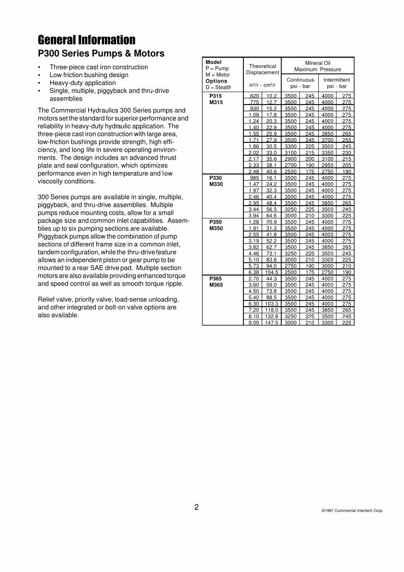
General InformationP300 Series Pumps & Motors
• Three-piece cast iron construction
• Low friction bushing design
• Heavy-duty application
• Single, multiple, piggyback and thru-drive
assembliesThe Commercial Hydraulics 300 Series pumps and
motors set the standard for superior performance andreliability in heavy-duty hydraulic application. Thethree-piece cast iron construction with large area,
low-friction bushings provide strength, high effi-ciency, and long life in severe operating environ-
ments. The design includes an advanced thrustplate and seal configuration, which optimizes
performance even in high temperature and lowviscosity conditions.
300 Series pumps are available in single, multiple,piggyback, and thru-drive assemblies. Multiple
pumps reduce mounting costs, allow for a smallpackage size and common inlet capabilities. Assem-
blies up to six pumping sections are available.Piggyback pumps allow the combination of pump
sections of different frame size in a common inlet,tandem configuration, while the thru-drive featureallows an independent piston or gear pump to be
mounted to a rear SAE drive pad. Multiple sectionmotors are also available providing enhanced torque
and speed control as well as smooth torque ripple.
Relief valve, priority valve, load-sense unloading,and other integrated or bolt-on valve options arealso available.
©1997 Commercial Intertech Co
P315 .620 10.2 3500 245 4000 275M315 .775 12.7 3500 245 4000 275
.930 15.2 3500 245 4000 2751.09 17.8 3500 245 4000 2751.24 20.3 3500 245 4000 2751.40 22.9 3500 245 4000 2751.55 25.9 3500 245 3850 2651.71 27.9 3500 245 3700 2551.86 30.5 3300 225 3500 2452.02 33.0 3100 215 3350 2302.17 35.6 2900 200 3100 2152.33 38.1 2700 190 2950 2052.48 40.6 2500 175 2750 190
P330 .985 16.1 3500 245 4000 275M330 1.47 24.2 3500 245 4000 275
1.97 32.3 3500 245 4000 2752.46 40.4 3500 245 4000 2752.95 48.4 3500 245 3850 2653.44 56.5 3250 225 3500 2453.94 64.6 3000 210 3300 225
P350 1.28 20.9 3500 245 4000 275M350 1.91 31.3 3500 245 4000 275
2.55 41.8 3500 245 4000 2753.19 52.2 3500 245 4000 2753.82 62.7 3500 245 3850 2654.46 73.1 3250 225 3500 2455.10 83.6 3000 210 3300 2255.73 94.0 2750 190 3000 2106.38 104.5 2500 175 2750 190
P365 2.70 44.3 3500 245 4000 275M365 3.60 59.0 3500 245 4000 275
4.50 73.8 3500 245 4000 2755.40 88.5 3500 245 4000 2756.30 103.3 3500 245 4000 2757.20 118.0 3500 245 3850 2658.10 132.8 3250 225 3500 2459.00 147.5 3000 210 3300 225
ModelP = PumpM = MotorOptionsD = Stealth
TheoreticalDisplacement
in3 /r - cm3 /r
Mineral OilMaximum Pressure
Continuouspsi - bar
Intermittentpsi - bar

8/10/2019 Catalogo Commercial Serie 300
http://slidepdf.com/reader/full/catalogo-commercial-serie-300 3/243
One-piece DriveShaft & Gear
Long Shaft Journals SuperiorBearing Surface
Internal Passage ConstantlyLubricates Bushings
Balanced Thrust PlatesMinimize Friction and Leakage
Extended Studs Availablefor Mounting Support
Large Passages for
Better Pump Feed
Cast Iron
Housings
Case Hardened GearsSAE 2- or 4-Bolt
Mountings
Split-flange or ODTPorts
High TemperatureSeals
Low-frictionBushing Coating
PL FactorEach section of a multiple pump or motor should be
regarded as a single unit with corresponding deliveryand power input requirements. Since the entire inputhorsepower is fed through a common drive shaft, the
power delivered to or from the unit is limited by thephysical strength of the shaft. This limit is defined as
a “PL” factor; “P” being the operating pressure and “L”the summation of gear widths.
In multiple units the “PL” must be calculated for thefirst connecting shaft as well as the drive shaft. Each
style or type of shaft has a unique “PL” factor asnoted in the table below.
Pressure X Total Gear Width = PL
PL MUST NOT EXCEED NUMBER SHOWN INCHART FOR APPROPRIATE SHAFT.
PL ChartShaft Style Integral Two-Piece
Shaft & Gear Style315SAE “A” Spline 4,450 -- (up to 1.25” GW)SAE “A” Key 3,600 --
SAE “B” Spline 13,400 --SAE “B” Key 9,900 --Connecting Shaft -- 5,550330SAE “B” Spline 8,450 6,250SAE “B” Key 6,250 6,250SAE “B-B” Spline 13,000 6,250SAE “B-B” Key 9,300 6,250SAE “C” Spline -- 6,250SAE “C” Key -- 6,250Connecting Shaft -- 6,250350SAE “B” Spline 6,450 4,500SAE “B” Key 4,750 4,750SAE “B-B” Spline 9,900 9,000SAE “B-B” Key 7,100 7,100
SAE “C” Spline 19,100 9,000SAE “C” Key 13,900 9,000Connecting Shaft -- 9,000365SAE “B” Spline 5,050 3,500SAE “B” Key 3,700 3,700SAE “B-B” Spline 7,750 5,350SAE “B-B” Key 5,550 5,550SAE “C” Spline 14,900 11,950SAE “C” Key 10,800 10,800Connecting Shaft -- 11,950

8/10/2019 Catalogo Commercial Serie 300
http://slidepdf.com/reader/full/catalogo-commercial-serie-300 4/244
General DataPump TypeHeavy duty, cast iron, external gear pump
MountingSAE standard flanges, ZF, others
PortingSAE split flanges and other types of threaded ports
(see table)
Shaft StyleSAE splined, keyed, and others
(see table)
DriveClockwise, counterclockwise, double. Direct drive
with flexible coupling is recommended. Pumps
subject to radial loads must be specified with an
outward bearing. Axial loading is not allowed.
SpeedFrom 400 to 3000 rev/min
Theoretical displacementsSee table
Maximum radial loads withoutboard bearingP 315 3200 N (only SEC - 90)
P 330 3500 N
P 350 5000 NP 365 6500 N
Inlet pressure30 psi/0,8 to 2,0 bar absolute at operating
temperature
Outlet pressure
See table
Hydraulic fluidsMineral oil, fire resistant fluids:
- water-oil emulsions 60/40, HFB- water-glycol, HFC
- phosphate-esters, HFD
Fluid temperatureMineral oil with standard seals:
0o F to 180o F (-20o C to +80o C)
Fire resistant fluids HFB, HFC
0o F to 180o F (-20o C to +60o C)
Fluid velocityFrom 7, 5 to 1600 cSt (50 to 7500 sus)
Recommended 15 to 75 cSt
FiltrationISO 4406 code:
- 19/16 at 2000 psi/ 140 bar
- 17/14 at 3000 psi/ 210 bar
- 15/12 at 4000 psi/ 275 bar
Flow velocityMineral oil and HFD:
- Inlet up to 8 fps/ 2,5 m/s
- Outlet up to 18 fps/ 6,0 m/s
Fire resistant fluids HFB, HFC
- Inlet up to 5 fps/ 1,5 m/s
- Outlet up to 13 fps/ 4,0 m/s
Multiple pump assembliesUp to 6 gear sections of the same model,
even with different gear widths
Piggyback assembliesSeveral models can be mounted together, one at the
rear of the other. Fluids are intermixing even from
separate reservoirs: 300/315, 350/315, 365/330,
365/330/315
Add-a-pump assembliesSimilar to piggyback, but fluids are not intermixing.
330/Al (Al: aluminum pumps)350/Al, 350/330, 350/350, 365/Al, 365/330, 365/350
Pumps with priority outletAvailable for models 315, 330, 350
• For operation outside given parameters, please
consult the Commercial representative in your area.
• The smallest gear width of each model is not
recommended for single units at the maximum
rated pressure
• Theoretical displacement is equal to the theoretical
flow at 1000 rev/min.

8/10/2019 Catalogo Commercial Serie 300
http://slidepdf.com/reader/full/catalogo-commercial-serie-300 5/245
Porting
ODT A B C D E
UNF mm mm mm mm
1/2” 3/4”-16 14,3 30,2 2,4 2,55
5/8” 7/8”-14 16,7 34,1 2,4 2,553/4” 1 1/16”-12 19,1 41,3 2,4 3,30
7/8” 1 3/16”-12 19,1 44,8 2,4 3,30
1” 1 5/16”-12 19,1 48,5 2,4 3,30
1 1/4” 1 5/8”-12 19,1 57,7 2,4 3,35
1 1/2” 1 7/8”-12 19,1 65,0 2,4 3,35
2” 2 1/2”-12 19,1 88,4 2,4 3,35
SAE Straight Thread (ODT)
SAE Flanged Ports Metric Thread (SSM)Port Size A B C D
inch mm mm mm mm mm0,50 12,7 17,5 38,1 M 8x1,25 23,90,75 19,1 22,2 47,6 M 10 x1,50 22,41,00 25,4 26,2 52,2 M 10 x1,50 22,4
1,25 31,8 30,2 58,7 M 10 x1,50 28,41,50 36,1 35,7 69,9 M 12 x1,75 26,92,00 50,8 42,9 77,8 M 12 x1,75 26,92,50 63,5 50,8 88,9 M 12 x1,75 30,2
SAE Flanged Ports UNC Thread (SSS)Port Size A B C D
inch mm mm mm mm mm0,50 12,7 17,5 38,1 5/16”-18 23,9
0,75 19,1 22,2 47,6 3/8”-16 22,4
1,00 25,4 26,2 52,2 3/8”-16 22,4
1,25 31,8 30,2 58,7 7/16”-14 28,4
1,50 36,1 35,7 69,9 1/2”-13 26,9
2,00 50,8 42,9 77,8 1/2”-13 26,92,50 63,5 50,8 88,9 1/2”-13 30,2
British Standard Pipe Parallel (BSPP)
BSPP A B C Dmm mm mm mm
0,50”-14 19,00 34,0 2,5 14,00,75”-14 24,50 40,0 2,5 16,01,00”-11 30,75 50,0 2,5 18,01,25”-11 39,50 58,0 2,5 20,01,50”-11 45,25 64,0 2,5 22,02,00”-11 56,25 78,0 3,0 24,0
Drive Shaft
Maximum Input Torque
Shaft Style P365P350P330P315
-
lb-ft Nm lb-ft Nmlb-ft Nmlb-ft Nm
-
-
-
-
-
-
-
-
-
-
-
-
-
-
-
-
-
--
-
-
-
SAE A
splined -
9 teeth
splined -
13 teeth
splined -
15 teeth
splined -
14 teeth
keyed
keyed
keyed
keyed
SAE B
SAE BB
SAE C
• integral: ;• 2 pieces: 2
80 109
62 84
242 328
-
-
-
167 226
;
2
;
2
;
2
;
2
;
2
;
2
;
2;
2
242 328 242 328 242 328
242 328242 328159 215
159 215
159 215
159 215
159 215
159 215
159 215
159 21590 122
55 74
2
; -
-
-
-
250 339
371 503
167 226 167 226 167 226
167 226167 226
371 503 371 503
371 503300 407
300 407
300 407
300 407
533 723
533 723
500 678
-
-
-
500 678500 678
300 407
708 960 708 960
250 339250 339
250 339 250 339
Connecting Shaft
DIN 5462 B8 x 32 x
36DIN 254 taper 1:5
8/10/2019 Catalogo Commercial Serie 300
http://slidepdf.com/reader/full/catalogo-commercial-serie-300 6/246
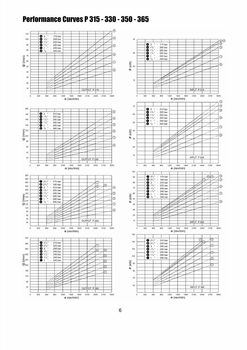
Performance Curves P 315 - 330 - 350 - 365

8/10/2019 Catalogo Commercial Serie 300
http://slidepdf.com/reader/full/catalogo-commercial-serie-300 7/247
Dimensional Data
Single Pumps & Motors
315
330
350
365
Dimensions Inches/mm
Model A B C** D* E F G H J(P) J(M)
4.27+GW 4.75 4.25 1.62 1.88 2.00 .75 3.27+GW 4.0 4.19108.5+GW 120.7108.0 41.1 47.8 50.8 19.1 83.1+GW 101.6 106.46.19+GW 5.88 6.88 1.62 3.12 2.56 .88 4.94+GW 4.81 5.00
157.2+GW 149.4 174.8 41.1 79.2 65.0 22.2 125.5+GW 122.2 127.07.06+GW 6.00 7.12 2.19 3.50 3.06 1.00 5.56+GW 5.75 5.75
179.3+GW 152.4 108.8 55.6 88.9 77.7 25.4 141.2+GW 146.1 146.17.31+GW 7.25 7.38 2.19 3.75 3.06 1.12 5.81+GW 6.25 6.25
185.7+GW 184.2 187.5 55.6 95.3 77.7 28.6 147.6+GW 158.8 158.8
315
330
350
365
Model
Dimensions Inches/mm
A B C** D* E F G H I J K L** M** N(P) N(M)7.05+T.GW 4.75 5.00 1.62 1.88 1.75 2.62 1.84 .34 .75 3.59+GW 2.25 2.75 4.0 4.19
179.1+T.GW 120.7 127.0 41.1 47.8 44.5 66.5 46.7 8.6 19.1 91.2+GW 57.2 69.9 101.6 106.49.88+T.GW 5.88 6.78 1.62 3.12 2.25 3.50 2.38 .62 .88 5.38+GW 3.09 3.69 4.81 5.00250.9+T.GW 149.4 172.2 41.1 79.2 57.2 88.9 60.5 15.7 22.2 136.7+GW 78.5 93.7 122.2 127.0
10.25+T.GW 6.00 7.69 2.19 3.50 2.25 3.50 2.50 .50 1.00 5.75+GW 3.56 4.12 5.75 5.75260.4+T.GW 152.4 195.3 55.6 88.9 57.2 88.9 63.5 12.7 25.4 146.1+GW 90.4 104.6 146.1 146.1
11.38+T.GW 7.25 8.38 2.19 3.75 2.62 4.00 2.88 .62 1.12 6.25+GW 3.69 4.69 6.25 6.25289.1+T.GW 184.2 212.9 55.6 95.3 66.5 101.6 73.3 15.7 28.6 158.8+GW 93.7 119.1 158.8 158.8
Tandem Pumps & Motors
WeightsThe following are the approximate weights of a
single 1” gear section in each frame size:P315 ........ 18 lbs. P330......... 36 lbs.
P350 ........ 51 lbs. P365......... 56 lbs.For each additional 1/4” of gear width add:P315 ............ 1 lb. P330..... 1 1/4 lbs.
P350 .... 1 1/2 lbs. P365..... 2 1/2 lbs.
* This dimension will vary with type of drive shaft. ** This dimension will vary with type of ports. T=Total.
Front View Side View Top View
Front View Side View Top View
To find the approximate weight of a multiplesection assembly, add the weight of each section as
a single. For the 330 frame size subtract 10% fromthis figure.
H
D E .50+ GW
F Shaft C
G
L
Port CL
B
A
D E .50+ GW
GShaft CL
Port CLA
.50+ GW
K
F
J
H
B
Port CLInlet Port C
L
N
CJ
P315 is 0.40 + GW.
P315 is 0.40 + GW.
I

8/10/2019 Catalogo Commercial Serie 300
http://slidepdf.com/reader/full/catalogo-commercial-serie-300 8/248
Note: In accordance with our policy of continuing product development, we reserve the right to change specifications shown in this catalog without notice.
315 Pump Performance Data
315 Motor Performance Data
900
1200
1500
1800
2100
2400
3000
Gear Widths
Speed 1” 1 1/4” 1 1/2” 1 3/4” 2”
RPM 3500 psi 3500 psi 3300 psi 2900 psi 2500 psiA B A B A B A B A B
7.1 665 8.3 830 9.6 940 10.9 965 12.2 95027 75.1 32 93.8 37 106.2 41 109.0 46 107.3
8.8 665 10.5 830 12.2 940 13.8 965 15.5 95033 75.1 40 93.8 46 106.2 52 109.0 59 107.3
10.6 660 12.6 825 14.7 935 16.7 955 18.8 94540 74.6 48 93.2 56 105.6 63 107.9 71 106.8
12.3 655 14.7 820 17.2 930 19.6 950 22.1 940
46 74.0 56 92.6 65 105.1 74 107.3 84 106.214.0 655 16.8 820 19.7 930 22.5 950 25.4 940
53 74.0 64 92.6 75 105.1 85 107.3 96 106.215.7 640 18.9 800 22.2 910 25.4 930 28.8 92059 72.3 72 90.4 84 102.8 96 105.1 109 103.9
19.0 640 23.0 800 27.2 905 31.2 925 35.3 91572 72.3 87 90.4 103 102.3 118 104.5 134 103.4
A: Input Flow GPM/LPM; B: Output Torque IN/LBS/Nm
Performance data shown are theaverage results based on a series oflaboratory tests of production units andare not necessarily representative of anyone unit. Tests were run with the oilreservoir temperature at 120°F andviscosity 150 SUS at 100°F.
Note: Pump output flow is at themaximum rated pressure (see page 13).
speed Gear Widthsrpm 1/2” 3/4” 1” 1 1/4” 1 1/2” 1 3/4” 2”
2.0 3.2 4.4 5.5 6.7 7.9 9.08 12 17 21 26 30 34
5 8 11 13 15 15 154 6 8 10 11 11 11
2.8 4.4 6.0 7.6 9.2 10.7 12.211 17 23 29 35 40 467 11 14 18 20 21 20
5 8 11 13 15 15 153.6 5.6 7.7 9.6 11.6 13.5 15.4
14 21 29 36 44 51 589 13 18 22 25 26 257 10 13 16 19 19 19
4.4 6.8 9.3 11.6 14.0 16.3 18.617 26 35 44 53 62 70
11 16 21 27 30 31 308 12 16 20 22 23 23
5.2 8.1 10.9 13.6 16.4 19.1 21.8
20 30 41 51 62 72 8312 19 25 31 35 36 35
9 14 18 23 26 27 266.0 9.3 12.5 15.6 18.8 21.9 25.1
23 35 47 59 71 83 9514 21 28 35 40 41 40
11 16 21 26 30 31 307.7 11.7 15.7 19.6 23.7 27.6 31.529 44 59 74 90 104 119
18 27 35 44 50 51 5113 20 26 33 37 38 38
output flow
input power GPM LPM
HP kW
GPM LPM
HP kW
GPM LPM HP
kW GPM
LPM HP
kW GPM
LPM HP kW
GPM LPM
HP kW
GPM
LPM HP
kW
900
1200
1500
1800
2100
2400
3000

8/10/2019 Catalogo Commercial Serie 300
http://slidepdf.com/reader/full/catalogo-commercial-serie-300 9/249
Note: In accordance with our policy of continuing product development, we reserve the right to change specifications shown in this catalog without notice.
330 Pump Performance Data
330 Motor Performance Data
900
1200
1500
1800
2100
2400
3000
Gear Widths
Speed 1” 1 1/4” 1 1/2” 1 3/4” 2”
RPM 3500 psi 3500 psi 3500 psi 3250 psi 3000 psiA B A B A B A B A B
10.1 1010 12.3 1270 14.5 1530 16.7 1665 19.0 177038 114.1 47 143.5 55 172.9 63 188.1 72 200.0
12.8 1005 15.7 1265 18.6 1525 21.4 1660 24.3 176049 113.6 59 142.9 70 172.3 81 187.6 92 198.9
15.6 1000 19.1 1255 22.6 1515 26.1 1650 29.6 175059 113.0 72 141.8 85 171.2 99 186.4 112 197.7
18.4 995 22.5 1250 26.6 1505 30.8 1640 34.9 1740
69 112.4 85 141.2 101 170.0 116 185.3 132 196.621.1 990 25.9 1240 30.7 1495 35.4 1625 40.2 1720
80 111.9 98 140.1 116 168.9 134 183.6 152 194.323.9 985 29.3 1235 34.7 1480 40.1 1605 45.5 1695
90 111.3 111 139.5 131 167.2 152 181.3 172 191.529.2 980 35.9 1230 42.6 1475 49.3 1595 56.0 1685110 110.7 136 139.0 161 166.7 186 180.2 212 190.4
A: Input Flow GPM/LPM; B: Output Torque IN/LBS/Nm
Performance data shown are theaverage results based on a series oflaboratory tests of production units andare not necessarily representative of anyone unit. Tests were run with the oilreservoir temperature at 120°F andviscosity 150 SUS at 100°F.
Note: Pump output flow is at themaximum rated pressure (see page 14).
speed Gear Widthsrpm 1/2” 3/4” 1” 1 1/4” 1 1/2” 1 3/4” 2”
3.2 5.1 7.0 8.8 10.6 12.4 14.312 19 26 33 40 47 549 13 17 21 26 28 29
6 10 13 16 19 21 22
4.5 7.0 9.5 12.0 14.5 16.9 19.417 26 36 45 55 64 7311 17 23 28 34 37 39
8 13 17 21 25 28 295.8 8.9 12.1 15.2 18.3 21.4 24.522 34 46 57 69 81 93
14 21 28 35 43 46 4911 16 21 26 32 34 36
7.1 10.8 14.7 18.4 22.1 25.9 29.627 41 55 70 84 98 112
17 26 34 43 51 55 5813 19 25 32 38 41 448.4 12.7 17.2 21.6 26.0 30.3 34.7
32 48 65 82 98 115 13120 30 40 50 60 65 68
15 22 30 37 44 48 519.6 14.7 19.8 24.8 29.8 34.8 39.8
36 55 75 94 113 132 15123 34 45 57 68 74 7817 25 34 42 51 55 58
12.2 18.5 24.9 31.2 37.5 43.8 50.146 70 94 118 142 166 190
28 43 57 71 85 92 9721 32 42 53 64 69 73
900
1200
1500
1800
2100
2400
3000
output flow input power
GPM LPM
HP kW
GPM LPM HP
kW GPM
LPM HP
kW GPM
LPM HP kW
GPM
LPM HP kW
GPM LPM HP
kW GPM
LPM HP
kW

8/10/2019 Catalogo Commercial Serie 300
http://slidepdf.com/reader/full/catalogo-commercial-serie-300 10/2410
Note: In accordance with our policy of continuing product development, we reserve the right to change specifications shown in this catalog without notice.
900
1200
1500
1800
2100
2400
Gear Widths
Speed 1” 1 1/4” 1 1/2” 1 3/4” 2” 2 1/4” 2 1/2”
RPM 3500 psi 3500 psi 3500 psi 3250 psi 3000 psi 2750 psi 2500 psiA B A B A B A B A B A B A B
13.4 1320 16.0 1670 18.6 2025 21.2 2225 23.8 2350 26.4 2425 28.9 245051 149.1 61 188.7 70 228.8 80 251.4 90 265.5 100 274.0 110 276.8
16.9 1315 20.4 1660 23.8 2015 27.2 2215 30.6 2340 34.0 2410 37.4 243564 148.6 77 187.6 90 227.7 103 250.3 116 264.4 129 272.3 142 275.1
20.5 1300 24.7 1640 28.9 1990 33.2 2195 37.4 2315 41.7 2385 45.9 241077 146.9 93 185.3 110 224.8 126 248.0 142 261.6 158 269.5 174 272.3
24.0 1295 29.0 1635 34.1 1980 39.2 2180 44.2 2300 49.3 2375 54.4 2395
91 146.3 110 184.7 129 223.7 148 246.3 167 259.9 187 268.3 206 270.627.5 1285 33.4 1620 39.3 1965 45.2 2165 51.1 2285 57.0 2355 62.9 2380
104 145.2 126 183.0 149 222.0 171 244.6 193 258.2 216 266.1 238 268.931.0 1265 37.7 1600 44.4 1940 51.2 2135 57.9 2255 64.6 2325 71.3 2350117 142.9 143 180.8 168 219.2 194 241.2 219 254.8 245 262.7 270 265.5
350 Pump Performance Data
350 Motor Performance Data
A: Input Flow GPM/LPM; B: Output Torque IN/LBS/Nm
Performance data shown arethe average results based on aseries of laboratory tests ofproduction units and are notnecessarily representative ofany one unit. Tests were runwith the oil reservoir tempera-ture at 120°F and viscosity
150 SUS at 100°F.
Note: Pump output flow is atthe maximum rated pressure(see page 16).
speed Gear Widthsrpm 1/2” 3/4” 1” 1 1/4” 1 1/2” 1 3/4” 2” 2 1/4” 2 1/2”
4.0 6.4 8.8 11.2 13.7 16.1 18.6 21.0 23.415 24 33 42 52 61 70 79 8911 17 22 28 33 36 38 39 40
8 12 17 21 25 27 28 29 30
5.6 8.8 12.1 15.4 18.7 21.9 25.2 28.4 31.721 33 46 58 71 83 95 108 12015 22 30 37 44 48 51 52 53
11 17 22 28 33 36 38 39 397.3 11.3 15.5 19.5 23.6 27.7 31.8 35.9 40.028 43 59 74 89 105 120 136 151
18 28 37 46 55 60 63 65 6614 21 28 34 41 45 47 49 49
8.9 13.8 18.8 23.6 28.6 33.5 38.4 43.3 48.334 52 71 89 108 127 145 164 183
22 33 44 55 67 72 76 78 7917 25 33 41 50 54 57 58 59
10.6 16.3 22.1 27.8 33.6 39.3 45.1 50.8 56.6
40 62 84 105 127 149 171 192 21426 39 52 65 78 84 89 91 92
19 29 39 48 58 63 66 68 6912.2 18.8 25.4 31.9 38.5 45.1 51.7 58.2 64.8
46 71 96 121 146 171 196 220 24530 44 59 74 89 96 101 105 10622 33 44 55 66 72 76 78 79
output flow input power
GPM LPM
HP kW
GPM LPM HP
kW GPM
LPM HP
kW GPM LPM
HP kW
GPM
LPM HP kW
GPM
LPM HP
kW
900
1200
1500
1800
2100
2400

8/10/2019 Catalogo Commercial Serie 300
http://slidepdf.com/reader/full/catalogo-commercial-serie-300 11/2411
900
1200
1500
1800
2100
2400
Gear Widths
Speed 1” 1 1/4” 1 1/2” 1 3/4” 2” 2 1/4” 2 1/2”
RPM 3500 psi 3500 psi 3500 psi 3500 psi 3500 psi 3250 psi 3000 psiA B A B A B A B A B A B A B
18.4 1865 22.0 2355 25.6 2860 29.2 3370 32.9 3850 36.5 4020 40.1 412570 210.7 83 266.1 97 323.1 111 380.8 124 435.0 138 454.2 152 466.1
23.3 1845 28.1 2330 32.9 2830 37.6 3335 42.4 3810 47.2 3980 52.0 4080
88 208.5 106 263.3 124 319.7 142 376.8 160 430.5 179 449.7 197 461.0
28.2 1815 34.1 2295 40.1 2780 46.0 3280 52.0 3750 57.9 3915 63.8 4020107 205.1 129 259.3 152 314.1 174 370.6 197 423.7 219 442.3 242 454.233.1 1805 40.2 2280 47.3 2765 54.4 3265 61.5 3730 68.6 3895 75.7 3995
125 203.9 152 257.6 179 312.4 206 368.9 233 421.4 260 440.1 287 451.437.9 1755 46.2 2220 54.4 2690 62.8 3160 71.1 3610 79.3 3770 87.6 3865
144 198.3 175 250.8 206 303.9 238 357.0 269 407.9 300 426.0 332 436.742.8 1705 52.3 2155 61.7 2615 71.2 3055 80.6 3490 90.1 3645 99.5 3740162 192.6 198 243.5 234 295.5 269 345.2 305 394.3 341 411.8 377 422.6
Note: In accordance with our policy of continuing product development, we reserve the right to change specifications shown in this catalog without notice.
365 Pump Performance Data
365 Motor Performance Data
A: Input Flow GPM/LPM; B: Output Torque IN/LBS/Nm
Performance data shown arethe average results based ona series of laboratory tests ofproduction units and are notnecessarily representative ofany one unit. Tests were runwith the oil reservoir tempera-ture at 120°F and viscosity
150 SUS at 100°F.
Note: Pump output flow is atthe maximum rated pressure(see page 18).
speed Gear Widths
rpm 3/4” 1” 1 1/4” 1 1/2” 1 3/4” 2” 2 1/4” 2 1/2”
8.0 11.5 14.9 18.4 21.8 25.4 28.8 32.330 44 57 70 83 96 109 122
24 31 39 47 55 63 66 6718 23 29 35 41 47 49 50
11.5 16.2 20.8 25.5 30.0 34.7 39.3 44.044 61 79 96 114 131 149 16631 42 52 63 73 84 88 90
23 31 39 47 55 63 65 6715.0 20.9 26.6 32.5 38.2 44.1 49.8 55.6
57 79 101 123 145 167 188 21139 52 66 79 92 105 110 112
29 39 49 59 68 78 82 8418.5 25.6 32.5 39.5 46.4 53.4 60.3 67.370 97 123 149 176 202 228 255
47 63 79 94 110 126 131 13535 47 59 70 82 94 98 101
22.0 30.2 38.3 46.5 54.6 62.8 70.8 79.083 114 145 176 207 238 268 299
55 73 92 110 128 147 153 15741 55 68 82 96 110 114 117
25.6 34.9 44.2 53.5 62.8 72.1 81.4 90.7
97 132 167 203 238 273 308 34363 84 105 126 147 168 175 180
47 63 78 94 110 125 131 134
900
1200
1500
1800
2100
2400
output input
GPM LPM HP
kW GPM
LPM HP
kW GPM LPM
HP kW
GPM LPM
HP kW
GPM LPM HP
kW GPM
LPM HP kW

8/10/2019 Catalogo Commercial Serie 300
http://slidepdf.com/reader/full/catalogo-commercial-serie-300 12/2412
315 Series Coding
Pump/Motor (1)P Pump
M Motor (no tandem motors available)
Unit (2)A Single Unit
B Tandem Unit (flush studs)
L Unit with Extended Studs
Shaft End Cover (3)1 Pump, cw w/o O.B. bearing
2 Pump, ccw w/o O.B. bearing
4 Pump, cw with O.B. bearing (Code 490 Only)
5 Pump, ccw with O.B. bearing (Code 590 Only)
9 Motor, bi-rot w/o O.B. bearing + 1/4” ODT drain
Shaft End Cover (4)90 4 bolt 72x100mm 80mm pilot
93 SAE “A” 2 bolt
95 Pad Mount for Clutch
96 SAE “B” 2 bolt
Port End Cover (5)
(Side Ported)IN OUT CW CCWı ı ı ı
SAE Split Flange (pump)
1” 3/4” EJ JE
1” 1/2” EK KE3/4” 3/4” EL LE
3/4” 1/2” EM ME
1” - OE EO
3/4” - OF FO
- 3/4” OJ JO
- 1/2” OL LO
SAE Split Flange (motor)
1” 1” DR-Double
3/4” 3/4” DS-Double
National Pipe Thread (pump)
1 1/4” 1” AJ JA1 1/4” 3/4” AK KA
1” 1” AL LA
1” 3/4” AM MA
3/4” 3/4” AR RA
National Pipe Thread (motor)
1” 1” DM-Double
3/4” 3/4” DN-Double
1/2” 1/2” DQ-Double
Unported (pump)
BI Unported
IN OUT CW CCWı ı ı ı
OD Tube Porting (pump)
1 1/4” 1” FB BF
1 1/4” 7/8” FC CF
1 1/4” 3/4” FG GF1 1/4” 5/8” FJ JF
1” 1” FL LF
1” 7/8” FV VF
1” 3/4” FW WF
1” 5/8” FX XF
7/8” 7/8” FY YF
7/8” 3/4” FZ ZF
7/8” 5/8” BC CB
7/8” 1/2” BG GB
3/4” 3/4” BJ JB
3/4” 5/8” BL LB
3/4” 1/2” BN NB
1 1/4” - BV VB1” - BW WB
7/8” - BX XB
3/4” - BY YB
- 1” BZ ZB
- 7/8” PD DP
- 3/4” PE EP
- 5/8” PM MP
- 1/2” PN NP
OD Tube Porting (motor)
1” 1” VN-Double
3/4” 3/4” VR-Double
1/2” 1/2” VQ-Double
(Side Ported) continuedIN OUT CW CCWı ı ı ı
BSPP Porting (pump)
1 1/4” 1” FN NF
1 1/4” 7/8” FP PF
1 1/4” 3/4” FR RF
1” 1” FS SF
1” 7/8” FT TF
1” 3/4” BP PB
7/8” 7/8” BQ QB
7/8” 3/4” BR RB
7/8” 1/2” BT TB
3/4” 3/4” BU UB
3/4” 1/2” PQ QP
1 1/4” - PR RP
1” - PS SP
7/8” - PT TP
3/4” - PV VP
- 1” P W WP
- 7/8” PX XP
- 3/4” PY YP
- 1/2” PZ ZP
IN OUT CW CCWı ı ı ı
BSPP Porting (motor)
1” 1” VY-Double
3/4” 3/4” VZ-Double
1/2” 1/2” VV-Double
Metric Split Flange (pump)
1” 3/4” EV VE
1” 1/2” EW WE
3/4” 3/4” EX XE
3/4” 1/2” EY YE
1” 0” OP PO
3/4” 0” O R RO
0” 3/4” OT TO
0” 1/2” OV VO
Metric Split Flange (motor)
1” 1” DV-Double
3/4” 3/4” DW-Double
(Rear Ported)
IN OUT CW CCWı ı ı ı
OD Tube Porting (pump)
1 1/4” 1” UC CU
1 1/4” 7/8” UF FU
1 1/4” 3/4” UN NU
1” 1” UD DU
1” 7/8” UP PU
1” 3/4” UQ QU
1” 5/8” UR RU
7/8” 7/8” LN NL
7/8” 3/4” LP PL
7/8” 5/8” LQ QL
3/4” 3/4” LR RL
3/4” 5/8” LS SL
3/4” 1/2” LT TL
OD Tube Porting (motor)
1” 1” RN-Double
3/4” 3/4” RQ-Double
1/2” 1/2” RS-Double
Gear Housing (6)AB Pump
EB Motor
IN OUT CW CCWı ı ı ı
BSPP Porting (pump)
1 1/4” 1” US SU
1 1/4” 7/8” UT TU
1 1/4” 3/4” UV VU
1” 1” UW WU
1” 7/8” UX XU
1” 3/4” UY YU
7/8” 7/8” LU UL
7/8” 3/4” LV VL
3/4 3/4 LX XL
3/4 1/2” LZ ZL
BSPP Porting (motor)
1” 1” RT-Double
3/4” 3/4” RV-Double1/2” 1/2” RW-Double
National Pipe Thread (motor)
1” 1” RX-Double
3/4” 3/4” RY-Double
1/2” 1/2” RZ-Double
(4)(1) (2) (3) (5) (6) (7) (8) (9) (6) (7) (10)
Tandem: Repeat if Necessary
3 1 5

8/10/2019 Catalogo Commercial Serie 300
http://slidepdf.com/reader/full/catalogo-commercial-serie-300 13/2413
Gear Width (7)Gear Width in.3/rev. cm3/rev. Max Pressure
03 3/8” .47 7.6 3500psi (241 bar)
05 1/2” .62 10.2 3500psi (241 bar)
06 5/8” .78 12.7 3500psi (241 bar)
07 3/4” .93 15.2 3500psi (241 bar)
08 7/8” 1.09 17.8 3500psi (241 bar)
10 1” 1.24 20.3 3500psi (241 bar)
11 1 1/8” 1.40 22.9 3500psi (241 bar)
12 1 1/4” 1.55 25.4 3500psi (241 bar)
13 1 3/8” 1.71 27.9 3500psi (241 bar)
15 1 1/2” 1.86 30.5 3300psi (228 bar)
16 1 5/8” 2.02 33.0 3100psi (214 bar)
17 1 3/4” 2.17 35.6 2900psi (200 bar)
18 1 7/8” 2.33 38.1 2700psi (186 bar)
20 2” 2.48 40.6 2500psi (172 bar)
Shaft Type (8)
(For Single or Tandem Units -unless noted)
97 SAE “A” Keyed
96 SAE “A” Splined
66 SAE “B” Keyed
65 SAE “B” Splined
60 Tapered, M12 x 1.5 thd. 3x5 mm Keyed; 1:5 taper (90 SEC Only)
56 Clutch Pump Tapered, 5/16 - 24 thd. (internal),
#6 Woodruff Keyed (single unit only); 1:4 taper
Bearing Carriers (9)(Dual Outlet - Pump Only)Outlets: for clockwise porting the top port number comes first;
for counter-clockwise porting the bottom port number comes first.
IN OUT CW CCWı ı ı
SAE Split Flange
1 1/4” 3/4” 3/4” CA AC
1 1/4” 3/4” 1/2” DA AD
1 1/4” 1/2” 1/2” EA AE
1” 3/4” 3/4” FA AF
1” 3/4” 1/2” GA AG
1” 1/2” 1/2” HA AH
OD Tube Porting
1 1/2” 1” 1” JG GJ
1 1/2” 1” 7/8” KG GK
1 1/2” 7/8” 7/8” LG GL
1 1/2” 1” 3/4” MG GM
1 1/2” 3/4” 3/4” NG GN
1 1/4” 1” 1” PG GP
1 1/4” 1” 7/8” QG GQ
1 1/4” 7/8” 7/8” RG GR
1 1/4” 1” 3/4” SG GS
1 1/4” 3/4” 3/4” TG GT
1 1/4” 3/4” 5/8” UG GU
1 1/4” 3/4” 1/2” VG GV
1 1/4” 5/8” 5/8” WG GW
1 1/4” 1/2” 1/2” XG GX
1” 1” 1” YG GY
1” 1” 7/8” ZG GZ
1” 7/8” 7/8” RC CR
1” 1” 3/4” SC CS
IN OUT CW CCWı ı ı
OD Tubing (continued)
1” 3/4” 3/4” TC CT
1” 3/4” 5/8” VC CV
1” 3/4” 1/2” WC CW
1” 5/8” 5/8” XC CX
1” 1/2” 1/2” YC CY
Metric Split Flange
1 1/4” 3/4” 3/4” BD DB
1 1/4” 3/4” 1/2” CD DC
1 1/4” 1/2” 1/2” ED DE
1” 3/4” 3/4” FD DF
1” 3/4” 1/2” GD DG
1” 1/2” 1/2” HD DH
BSPP Porting
1 1/2” 1” 1” HJ JH
1 1/2” 1” 7/8” KJ JK
1 1/2” 7/8” 7/8” LJ JL
1 1/2” 1” 3/4” MJ JM
1 1/2” 3/4” 3/4” NJ JN
1 1/4” 1” 1” PJ JP
1 1/4” 1” 7/8” QJ JQ
1 1/4” 7/8” 7/8” RJ JR
1 1/4” 1” 3/4” SJ JS
1 1/4” 3/4” 3/4” TJ JT
1 1/4” 3/4” 1/2” UJ JU
(Dual Outlet) continued
IN OUT CW CCWı ı ı
BSPP Porting (continued)
1 1/4” 1/2” 1/2” VJ JV
1” 1” 1” WJ JW
1” 1” 7/8” XJ JX
1” 7/8” 7/8” YJ JY
1” 1” 3/4” ZJ JZ1” 3/4” 3/4” JD DJ
1” 3/4” 1/2” KD DK
1” 1/2” 1/2” LD DL
(Single Outlet - Pump Only) Outlet for front section.
IN OUT CW CCWı ı ı ı
SAE Split Flange
1 1/4” 1 1/4” CJ JC
1 1/4” 1” CL LC
1 1/4” 3/4” CM MC
1 1/4” 1/2” HB BH
1” 1” HC CH1” 3/4” HF FH
1” 1/2” HL LH
3/4” 3/4” HM MH
3/4” 1/2” HN NH
OD Tube Porting
1 1/2” 1 1/2” KB BK
1 1/2” 1 1/4” KC CK
1 1/2” 1” KF FK
1 1/2” 7/8” KL LK
1 1/2” 3/4” KM MK
1 1/4” 1 1/4” KN NK
1 1/4” 1” KO OK1 1/4” 7/8” KP PK
1 1/4” 3/4” KQ QK
1 1/4” 5/8” MB BM
1 1/4” 1/2” ML LM
1” 1” MN NM
1” 7/8” MQ QM
1” 3/4” MR RM
1” 5/8” MS SM
1” 1/2” MT TM
3/4” 3/4” MU UM
3/4” 5/8” MV VM
3/4” 1/2” MW WM
Connecting Shaft (10)
For connecting tandem units.
1 Connecting Shaft
IN OUT CW CCWı ı ı ı
Metric Split Flange
1 1/4” 1 1/4” CN NC
1 1/4” 1” CP PC
1 1/4” 3/4” CQ QC
1 1/4” 1/2” HR RH
1” 1” HS SH1” 3/4” HT TH
1” 1/2” HU UH
3/4” 3/4” HV VH
3/4” 1/2” HW WH
BSPP Porting
1 1/2” 1 1/2” KR RK
1 1/2” 1 1/4” KS SK
1 1/2” 1” KT TK
1 1/2” 7/8” KU UK
1 1/2” 3/4” KV VK
1 1/4” 1 1/4” KW WK
1 1/4” 1” KX XK1 1/4” 7/8” KY YK
1 1/4” 3/4” KZ ZK
1 1/4” 1/2” HO OH
1” 1” HP PH
1” 7/8” HQ QH
1” 3/4” HX XH
1” 1/2” HY YH
3/4” 3/4” HZ ZH
3/4” 1/2” MX XM
Common Inlet Passage
No Ports C D

8/10/2019 Catalogo Commercial Serie 300
http://slidepdf.com/reader/full/catalogo-commercial-serie-300 14/2414
330 Series Coding
Pump/Motor (1)
P Pump
M Motor
Unit (2)A Single Unit
B Tandem Unit (flush studs)
C Single or Tandem w. two-piece shaft (O.B. bearing required)
L Unit with Extended Studs
Shaft End Cover (3)1 Pump, cw w/o O.B. bearing
2 Pump, ccw w/o O.B. bearing
4 Pump, cw with O.B. bearing
5 Pump, ccw with O.B. bearing
8 Motor, bi-rot w/ O.B. bearing + 1/4” ODT drain9 Motor, bi-rot w/o O.B. bearing + 1/4” ODT drain
18 Motor, bi-rot w/ O.B. bearing + 1/4” BSPP drain (78 only)
19 Motor, bi-rot w/o O.B. bearing + 1/4” BSPP drain (42 & 78 only)
Shaft End Cover (4)42 SAE 4 bolt “B”
78 SAE 4 bolt “C”
97 SAE 2 bolt “B”
Port End Cover (5)(Side Ported)
IN OUT CW CCW
ı ı ı ıSAE Split Flange (pump)
1 1/2”1 1/4” EJ JE
1 1/2” 1” EK KE
1 1/4”1 1/4” EL LE
1 1/4” 1” E M ME
1” 1” EN NE
1 1/2” - OF FO
1 1/4” - OG GO
1” - OJ JO
- 1 1/4” OM MO
- 1” O N NO
SAE Split Flange (motor) 1 1/4”1 1/4” CS-Double
1” 1” CT-Double
3/4” 3/4” CV-Double
OD Tube Porting (pump)
1 1/4” 1” FJ JF
1” 1” FL LF
1 1/4” - BG GB
1” - BJ JB
- 1” BN NB
IN OUT CW CCW
ı ı ı ıOD Tube Porting (motor)
1 1/4”1 1/4” VC-Double
1” 1” VN-Double
3/4” 3/4” VR-Double
Metric Split Flange (pump)
1 1/2”1 1/4” EV VE
1 1/2” 1” E W WE
1 1/4”1 1/4” EX XE
1 1/4” 1” EY YE
1” 1” EZ ZE
1 1/2” - OR RO
1 1/4” - OS SO1” - OT TO
- 1 1/4” OW WO
- 1” OX XO
Unported (pump)
BI Unported
Unported (motor)
BA Unported
(Side Ported)continued
IN OUT CW CCWı ı ı ı
Metric Split Flange (motor)
1 1/4”1 1/4” CX-Double
1” 1” CY-Double
3/4” 3/4” CZ-Double
Metric Straight Thread (motor)
1 1/4”1 1/4” VS-Double
1” 1” VT-Double
3/4” 3/4” VW-Double
IN OUT CW CCWı ı ı ı
BSPP Porting (pump)
1 1/4” 1” FS SF
1” 1” FT TF
1 1/4” - BQ QB
1” - BR RB
- 1” BU UB
BSPP Porting (motor)
1 1/4”1 1/4” VX-Double
1” 1” VY-Double
3/4” 3/4” VZ-Double
Gear Housing (6)
AB Pump
EB Motor
Gear Width (7)Gear Width in.3/rev. cm3/rev. Max Pressure
05 1/2” .99 16.1 3500psi (241 bar)
07 3/4” 1.48 24.2 3500psi (241 bar)
10 1” 1.97 32.3 3500psi (241 bar)
12 1 1/4” 2.46 40.4 3500psi (241 bar)
15 1 1/2” 2.96 48.4 3500psi (241 bar)
17 1 3/4” 3.45 56.5 3250psi (224 bar)
20 2” 3.94 64.6 3000psi (207 bar)
Shaft Type (8)
(For Single, Tandem or Two-piece Shaft -unless noted)
07 SAE “C” Spline (two-piece only)
25 SAE “B” Spline
30 SAE “B” Keyed
98 SAE “BB” Splined
43 SAE “BB” Keyed
(4)(2) (5) (6) (7) (8) (9) (6) (7) (10)
Tandem: Repeat if Necessary
(3)
3 3 0
(1)

8/10/2019 Catalogo Commercial Serie 300
http://slidepdf.com/reader/full/catalogo-commercial-serie-300 15/2415
Bearing Carriers (9)(Dual Outlet - Pump Only)
Outlets: for clockwise porting the top port number comes first;
for counter-clockwise porting the bottom port number comes first.
IN OUT CW CCWı ı ı
SAE Split Flange
2” 1 1/4” 1 1/4” AM MA
2” 1 1/4” 1” AN NA2” 1” 1” AP PA
1 1/2” 1 1/4” 1 1/4” AT TA
1 1/2” 1 1/4” 1” AU UA
1 1/2” 1” 1” AV VA
1 1/4” 1 1/4” 1 1/4” AW WA
1 1/4” 1 1/4” 1” AX XA
1 1/4” 1” 1” AY YA
1” 1” 1” AZ ZA
Metric Split Flange
2” 1 1/4” 1 1/4” DM MD
2” 1 1/4” 1” DN ND
2” 1” 1” DP PD1 1/2” 1 1/4” 1 1/4” DT TD
1 1/2” 1 1/4” 1” DU UD
1 1/2” 1” 1” DV VD
1 1/4” 1 1/4” 1 1/4” DW WD
1 1/4” 1 1/4” 1” DX XD
1” 1” 1” DZ ZD
IN OUT CW CCWı ı ı
OD Tube Porting
1 1/2” 1” 1” GV VG
1 1/4” 1” 1” GY YG1” 1” 1” GZ ZG
(Combined Outlet)
IN OUT CW CCWı ı ı ı
SAE Split Flange (pump)
2” 1 1/2” UN NU
2” 1 1/4” UO OU
1 1/2” 1 1/2” UP PU
1 1/2” 1 1/4” UQ QU
1 1/4” 1 1/4” UR RU
SAE Split Flange (motor)
1 1/2”1 1/2” BB-Double
1 1/4”1 1/4” CC-Double
1” 1” EE-Double
3/4” 3/4” FF-Double
OD Tube Porting (pump)
1 1/2” 1 1/4” PQ QP
1 1/4” 1 1/4” PR RP
OD Tube Porting (motor)
1 1/4”1 1/4” NN-Double1” 1” QQ-Double
3/4” 3/4” RR-Double
Common Inlet Passage (pump)
No Ports C D
Connecting Shaft (10)
For connecting tandem units.
1 Connecting Shaft
IN OUTı ı
Metric Split Flange (motor)
1 1/2” 1 1/2” HH-Double
1 1/4” 1 1/4” JJ-Double
1” 1” KK-Double
3/4” 3/4” LL-Double
BSPP Porting (motor)
1 1/4” 1 1/4” XX-Double
1” 1” YY-Double
3/4” 3/4” ZZ-Double
Metric Straight Thread (motor)
1 1/4” 1 1/4” TT-Double
1” 1” UU-Double
3/4” 3/4” VV-Double
IN OUT CWCCW
ı ı ı ı
Metric Split Flange 2” 1 1/2” HR RH
2” 1 1/4” HS SH
2” 1” HT TH
1 1/2” 1 1/2” HU UH
1 1/2” 1 1/4” HV VH
1 1/2” 1” HW WH
1 1/4” 1 1/4” HX XH
1 1/4” 1” HY YH
1” 1” HZ ZH
*
* Outlet port for rear section.
(Single Outlet - Pump Only)
Outlet is for front section.
IN OUT CW CCW
ı ı ı ı
SAE Split Flange 2” 1 1/2” HB BH
2” 1 1/4” HC CH
2” 1” HF FH
1 1/2” 1 1/2” HL LH
1 1/2” 1 1/4” HM MH
1 1/2” 1” HN NH
1 1/4” 1 1/4” HO OH
1 1/4” 1” HP PH
1” 1” HQ QH
1 1/4” 1” RS SR
OD Tube Porting
1 1/2” 1 1/4” - KM MK
1 1/2” 1” - KN NK
1 1/4” 1 1/4” - KO OK
1 1/4” 1” - KP PK
1” 1” - KQ QK

8/10/2019 Catalogo Commercial Serie 300
http://slidepdf.com/reader/full/catalogo-commercial-serie-300 16/2416
350 Series Coding
Pump/Motor (1)
P Pump
M Motor
Unit (2)A Single Unit
B Tandem Unit (flush studs)
C Single or Tandem w. two-piece shaft (O.B. bearing required)
L Unit with Extended Studs
Shaft End Cover (3)1 Pump, cw w/o O.B. bearing
2 Pump, ccw w/o O.B. bearing
4 Pump, cw with O.B. bearing
5 Pump, ccw with O.B. bearing
8 Motor, bi-rot w/ O.B. bearing + 1/4” ODT drain9 Motor, bi-rot w/o O.B. bearing + 1/4” ODT drain
18 Motor, bi-rot w/ O.B. bearing + 1/4” BSPP drain (78 Only)
19 Motor, bi-rot w/o O.B. bearing + 1/4” BSPP drain (78 Only)
Shaft End Cover (4)42 SAE 4 bolt “B”
46 SAE 2/4 bolt “B”
62 “ZF” 4 bolt (462 only) - 80 mm pilot, 80x80 mm
78 SAE 4 bolt “C”
97 SAE 2 bolt “B”
98 SAE 2 bolt “C”
Port End Cover (5)(Side Ported)
IN OUT CW CCWı ı ı ı
SAE Split Flange (pump)
2” 1 1/2” EC CE
2” 1 1/4” EF FE
2” 1” EG GE
1 1/2”1 1/2” EH HE
1 1/2”1 1/4” EJ JE
1 1/2” 1” EK KE
1 1/4”1 1/4” EL LE
1 1/4” 1” E M ME
1” 1” EN NE2” - OE EO
1 1/2” - OF FO
1 1/4” - OG GO
1” - OJ JO
- 1 1/2” OL LO
- 1 1/4” OM MO
- 1” O N NO
SAE Split Flange (motor)
1 1/2”1 1/2” CR-Double
1 1/4”1 1/4” CS-Double
1” 1” CT-Double
3/4” 3/4” CV-Double
IN OUT CW CCWı ı ı ı
OD Tube Porting (pump)
1 1/2”1 1/4” FB BF
1 1/2” 1” FC CF
1 1/4”1 1/4” FG GF
1 1/4” 1” FJ JF
1” 1” FL LF
1 1/2” - BC CB
1 1/4” - BG GB
1” - BJ JB
- 1 1/4” BL LB- 1” BN NB
OD Tube Porting (motor)
1 1/4”1 1/4” VC-Double
1” 1” VN-Double
3/4” 3/4” VR-Double
Unported (pump)
Unported BI IB
Unported (motor)
BA Unported
(Side Ported)continued
IN OUT CW CCWı ı ı ı
Metric Split Flange (pump)
2” 1 1/2” ER RE
2” 1 1/4” ES SE
2” 1” ET TE
1 1/2”1 1/2” EU UE
1 1/2”1 1/4” EV VE
1 1/2” 1” E W WE
1 1/4”1 1/4” EX XE
1 1/4” 1” EY YE
1” 1” EZ ZE
2” - OP PO
1 1/2” - OR RO
1 1/4” - OS SO
1” - OT TO
- 1 1/2” OV VO
- 1 1/4” OW WO
- 1” OX XO
Metric Split Flange (motor)
1 1/2”1 1/2” CW-Double
1 1/4”1 1/4” CX-Double
1” 1” CY-Double
3/4” 3/4” CZ-Double
IN OUT CW CCWı ı ı ı
Metric Straight Thread (motor)
1 1/4”1 1/4” VS-Double
1” 1” VT-Double
3/4” 3/4” VW-Double
BSPP Porting (pump)
1 1/2”1 1/4” FN NF
1 1/2” 1” FP PF
1 1/4”1 1/4” FR RF
1 1/4” 1” FS SF
1” 1” FT TF
1 1/2” - BP PB
1 1/4” - BQ QB
1” - BR RB
- 1 1/4” BT TB
- 1” BU UB
BSPP Porting (motor)
1 1/4”1 1/4” VX-Double
1” 1” VY-Double
3/4” 3/4” VZ-Double
Gear Housing (6)
AB PumpEB Motor
Gear Width (7)Gear Width in.3/rev. cm3/rev. Max Pressure
05 1/2” 1.28 20.9 3500psi (241 bar)
07 3/4” 1.91 31.3 3500psi (241 bar)
10 1” 2.55 41.8 3500psi (241 bar)
12 1 1/4” 3.19 52.2 3500psi (241 bar)
15 1 1/2” 3.83 62.7 3500psi (241 bar)
17 1 3/4” 4.46 73.1 3250psi (224 bar)
20 2” 5.10 83.6 3000psi (207 bar)
22 2 1/4” 5.74 94.0 2750psi (190 bar)25 2 1/2” 6.38 104.5 2500psi (172 bar)
(4)(2) (5) (6) (7) (8) (9) (6) (7) (10)
Tandem: Repeat if Necessary
(3)
3 5 0
(1)

8/10/2019 Catalogo Commercial Serie 300
http://slidepdf.com/reader/full/catalogo-commercial-serie-300 17/2417
Shaft Type (8)(For Single, Tandem or Two-piece Shaft -unless noted)
06 88X32X36 DIN 5462 Spline (two-piece only)
07 SAE “C” Spline
11 SAE “C” Keyed
25 SAE “B” Spline
43 SAE “BB” Keyed
73 SAE “C” Keyed Long (single and two-piece only)
98 SAE “BB” Splined (tandem only)
Bearing Carriers (9)
(Dual Outlet - Pump Only)Outlets: for clockwise porting the top port number comes first;
for counter-clockwise porting the bottom port number comes first.
IN OUT CW CCWı ı ı
SAE Split Flange
2 1/2” 1 1/4” 1 1/4” AF FA
2 1/2” 1 1/4” 1” AG GA
2 1/2” 1” 1” AH HA
2” 1 1/4” 1 1/4” AM MA
2” 1 1/4” 1” AN NA2” 1” 1” AP PA
1 1/2” 1 1/4” 1 1/4” AT TA
1 1/2” 1 1/4” 1” AU UA
1 1/2” 1” 1” AV VA
1 1/4” 1 1/4” 1 1/4” AW WA
1 1/4” 1 1/4” 1” AX XA
1 1/4” 1” 1” AY YA
1” 1” 1” AZ ZA
Metric Split Flange
2” 1 1/4” 1 1/4” DM MD
2” 1 1/4” 1” DN ND
2” 1” 1” DP PD
1 1/2” 1 1/4” 1 1/4” DT TD
1 1/2” 1 1/4” 1” DU UD
1 1/2” 1” 1” DV VD
1 1/4” 1 1/4” 1 1/4” DW WD
1 1/4” 1 1/4” 1” DX XD
1 1/4” 1” 1” DY YD
1” 1” 1” DZ ZD
IN OUT CW CCWı ı ı
OD Tube Porting
2” 1 1/4” 1 1/4” GM MG
2” 1 1/4” 1” GN NG
2” 1” 1” GP PG
1 1/2” 1 1/4” 1 1/4” GT TG
1 1/2” 1 1/4” 1” GU UG
1 1/2” 1” 1” GV VG
1 1/4” 1 1/4” 1 1/4”GW WG
1 1/4” 1 1/4” 1” GX XG
1 1/4” 1” 1” GY YG
1” 1” 1” GZ ZG
(Combined Outlet)IN OUT CW CCWı ı ı ı
SAE Split Flange (pump)
2” 1 1/2” UN NU
2” 1 1/4” UO OU
1 1/2” 1 1/2” UP PU
1 1/2” 1 1/4” UQ QU
1 1/4” 1 1/4” UR RU
SAE Split Flange (motor)
2” 2” AA-Double
1 1/2”1 1/2” BB-Double
1 1/4”1 1/4” CC-Double
1” 1” EE-Double
3/4” 3/4” FF-Double
OD Tube Porting (pump)
2” 1 1/2” PE EP2” 1 1/4” PM MP
1 1/2” 1 1/2” PN NP
1 1/2” 1 1/4” PQ QP
1 1/4” 1 1/4” PR RP
OD Tube Porting (motor)
1 1/2”1 1/2” MM-Double
1 1/4”1 1/4” NN-Double
1” 1” QQ-Double
3/4” 3/4” RR-Double
Common Inlet Passage
No Ports C D
Connecting Shaft (10)
For connecting tandem units.
1 Connecting Shaft
IN OUTı ı
Metric Split Flange (motor)
2” 2” GG-Double
1 1/2” 1 1/2” HH-Double
1 1/4” 1 1/4” JJ-Double
1” 1” KK-Double
3/4” 3/4” LL-Double
BSPP Porting (motor)
1 1/2” 1 1/2” WW-Double
1 1/4” 1 1/4” XX-Double
1” 1” YY-Double
3/4” 3/4” ZZ-Double
Metric Straight Thread (motor)
1 1/2” 1 1/2” SS-Double
1 1/4” 1 1/4” TT-Double1” 1” UU-Double
3/4” 3/4” VV-Double
(Single Outlet - Pump Only) Outlet for front section.
IN OUT CW CCW
ı ı ı ı
SAE Split Flange 2” 1 1/2” HB BH
2” 1 1/4” HC CH
2” 1” HF FH
1 1/2” 1 1/2” HL LH
1 1/2” 1 1/4” HM MH
1 1/2” 1” HN NH
1 1/4” 1 1/4” HO OH
1 1/4” 1” HP PH
1” 1” HQ QH
1 1/4” 1” RS SR
IN OUT CWCCW
ı ı ı ı
OD Tube Porting 2” 1 1/2” KB BK
2” 1 1/4” KC CK
2” 1” KF FK
1 1/2” 1 1/2” KL LK
1 1/2” 1 1/4” KM MK
1 1/2” 1” KN NK
1 1/4” 1 1/4” KO OK
1 1/4” 1” KP PK
1” 1” KQ QK
(Single Outlet)IN OUT CW CCWı ı ı ı
BSPP Porting
2” 1 1/2” KR RK
2” 1 1/4” KS SK
2” 1” KT TK
1 1/2” 1 1/2” KU UK
1 1/2” 1 1/4” KV VK
1 1/2” 1” KW WK
1 1/4” 1 1/4” KX XK
1 1/4” 1” KY YK
1” 1” KZ ZK
*
* Outlet port for rear section.

8/10/2019 Catalogo Commercial Serie 300
http://slidepdf.com/reader/full/catalogo-commercial-serie-300 18/2418
365 Series Coding
Pump/Motor (1)
P Pump
M Motor
Unit (2)A Single Unit
B Tandem Unit (flush studs)
C Single or Tandem w. two-piece shaft (O.B. bearing required)
L Unit Extended Studs
Shaft End Cover (3)1 Pump, cw w/o O.B. bearing
2 Pump, ccw w/o O.B. bearing
4 Pump, cw with O.B. bearing
5 Pump, ccw with O.B. bearing
8 Motor, bi-rot w/ O.B. bearing + 1/4” ODT drain9 Motor, bi-rot w/o O.B. bearing + 1/4” ODT drain
Shaft End Cover (4)42 SAE 4 bolt “B”
78 SAE 4 bolt “C”
97 SAE 2 bolt “B”
98 SAE 2 bolt “C”
Port End Cover (5)(Side Ported)
IN OUT CW CCWı ı ı ı
SAE Split Flange (pump) 2” 1 1/2” EC CE
2” 1 1/4” EF FE
2” 1” EG GE
1 1/2”1 1/2” EH HE
1 1/2”1 1/4” EJ JE
1 1/2” 1” EK KE
1 1/4”1 1/4” EL LE
1 1/4” 1” E M ME
1” 1” EN NE
2” - OE EO
1 1/2” - OF FO
1 1/4” - OG GO
1” - OJ JO- 1 1/2” OL LO
- 1 1/4” OM MO
- 1” O N NO
SAE Split Flange (motor)
1 1/2”1 1/2” CR-Double
1 1/4”1 1/4” CS-Double
1” 1” CT-Double
3/4” 3/4” CV-Double
IN OUT CW CCWı ı ı ı
OD Tube Porting (pump) 1 1/2”1 1/4” FB BF
1 1/2” 1” FC CF
1 1/4”1 1/4” FG GF
1 1/4” 1” FJ JF
1” 1” FL LF
1 1/2” - BC CB
1 1/4” - BG GB
1” - BJ JB
- 1 1/4” BL LB
- 1” BN NB
OD Tube Porting (motor)
1 1/4”1 1/4” VC-Double
1” 1” VN-Double
3/4” 3/4” VR-Double
Unported (pump)
Unported BI IB
Unported (motor)
BA Unported
(Side Ported)continued
IN OUT CW CCWı ı ı ı
Metric Split Flange (pump)
2” 1 1/2” ER RE
2” 1 1/4” ES SE
2” 1” ET TE
1 1/2”1 1/2” EU UE
1 1/2”1 1/4” EV VE
1 1/2” 1” E W WE
1 1/4”1 1/4” EX XE
1 1/4” 1” EY YE
1” 1” EZ ZE
2” - OP PO
1 1/2” - OR RO
1 1/4” - OS SO
1” - OT TO
- 1 1/2” OV VO
- 1 1/4” OW WO
- 1” OX XO
Metric Split Flange (motor)
1 1/2”1 1/2” CW-Double
1 1/4”1 1/4” CX-Double
1” 1” CY-Double
3/4” 3/4” CZ-Double
IN OUT CW CCWı ı ı ı
Metric Straight Thread (motor)
1 1/4”1 1/4” VS-Double
1” 1” VT-Double
3/4” 3/4” VW-Double
BSPP Porting (pump)
1 1/2”1 1/4” FN NF
1 1/2” 1” FP PF
1 1/4”1 1/4” FR RF
1 1/4” 1” FS SF
1” 1” FT TF
1 1/2” - BP PB
1 1/4” - BQ QB
1” - BR RB
- 1 1/4” BT TB
- 1” BU UB
BSPP Porting (motor)
1 1/4”1 1/4” VX-Double
1” 1” VY-Double
3/4” 3/4” VZ-Double
Gear Housing (6)
AB Pump
EB Motor
Gear Width (7)Gear Width in.3/rev. cm3/rev. Max Pressure
07 3/4” 2.70 44.3 3500psi (241 bar)
10 1” 3.60 59.0 3500psi (241 bar)
12 1 1/4” 4.50 73.8 3500psi (241 bar)
15 1 1/2” 5.40 88.5 3500psi (241 bar)
17 1 3/4” 6.30 103.3 3500psi (241 bar)
20 2” 7.20 118.0 3500psi (241 bar)
22 2 1/4” 8.10 132.8 3250psi (224 bar)
25 2 1/2” 9.00 147.5 3000psi (207 bar)
(4)(2) (5) (6) (7) (8) (9) (6) (7) (10)
Tandem: Repeat if Necessary
3 6 5
(1) (3)

8/10/2019 Catalogo Commercial Serie 300
http://slidepdf.com/reader/full/catalogo-commercial-serie-300 19/2419
Shaft Type (8)(For Single, Tandem or Two-piece Units -unless noted)
07 SAE “C” Spline (single and tandem only)
11 SAE “C” Keyed
25 SAE “B” Spline (single only)
Bearing Carriers (9)
(Dual Outlet - Pump Only)
Outlets: for clockwise porting the top port number comes first;for counter-clockwise porting the bottom port number comes first.
IN OUT CW CCW
ı ı ı
SAE Sp lit Flange
2 1/2” 1 1/2” 1 1/2” AC CA
2 1/2” 1 1/2” 1 1/4” AD DA
2 1/2” 1 1/2” 1” AE EA
2 1/2” 1 1/4” 1 1/4” AF FA
2 1/2” 1 1/4” 1” AG GA
2 1/2” 1” 1” AH HA
2” 1 1/2” 1 1/2” AJ JA
2” 1 1/2” 1 1/4” AK KA
2” 1 1/2” 1” AL LA
2” 1 1/4” 1 1/4” AM MA
2” 1 1/4” 1” AN NA
2” 1” 1” AP PA
1 1/2” 1 1/2” 1 1/2” AQ QA
1 1/2” 1 1/2” 1 1/4” AR RA
1 1/2” 1 1/2” 1” AS SA
1 1/2” 1 1/4” 1 1/4” AT TA
1 1/2” 1 1/4” 1” AU UA
1 1/2” 1” 1” AV VA
1 1/4” 1 1/4” 1 1/4” AW WA
1 1/4” 1 1/4” 1” AX XA
1 1/4” 1” 1” AY YA1” 1” 1” AZ ZA
OD Tube Porting
2” 1 1/2” 1 1/2” GJ JG
2” 1 1/2” 1 1/4” GK KG
2” 1 1/2” 1” GL LG
2” 1 1/4” 1 1/4” GM MG
2” 1 1/4” 1” GN NG
2” 1” 1” GP PG
1 1/2” 1 1/2” 1 1/2” GQ QG
1 1/2” 1 1/2” 1 1/4” GR RG
1 1/2” 1 1/2” 1” GS SG
1 1/2” 1 1/4” 1 1/4” GT TG1 1/2” 1 1/4” 1” GU UG
1 1/2” 1” 1” GV VG
1 1/4” 1 1/4” 1 1/4”GW WG
1 1/4” 1 1/4” 1” GX XG
1 1/4” 1” 1” GY YG
1” 1” 1” GZ ZG
(Combined Outlet)
IN OUT CW CCWı ı ı ı
SAE Split Flange (pump)
2 1/2” 1 1/2” UC CU
2 1/2” 1 1/4” UF FU
2” 1 1/2” UN NU
2” 1 1/4” UO OU
1 1/2” 1 1/2” UP PU
1 1/2” 1 1/4” UQ QU
1 1/4” 1 1/4” UR RU
SAE Split Flange (motor)
2” 2” AA-Double
1 1/2”1 1/2” BB-Double
1 1/4”1 1/4” CC-Double
1” 1” EE-Double
3/4” 3/4” FF-Double
OD Tube Porting (pump)
2” 1 1/2” PE EP
2” 1 1/4” PM MP1 1/2” 1 1/2” PN NP
1 1/2” 1 1/4” PQ QP
1 1/4” 1 1/4” PR RP
OD Tube Porting (motor)
1 1/2”1 1/2” MM-Double
1 1/4”1 1/4” NN-Double
1” 1” QQ-Double
3/4” 3/4” RR-Double
IN OUTı ı
Metric Split Flange (motor)
2” 2” GG-Double
1 1/2” 1 1/2” HH-Double
1 1/4” 1 1/4” JJ-Double
1” 1” KK-Double
3/4” 3/4” LL-Double
BSPP Porting (motor)
1 1/2” 1 1/2” WW-Double
1 1/4” 1 1/4” XX-Double
1” 1” YY-Double
3/4” 3/4” ZZ-Double
Metric Straight Thread (motor)
1 1/2” 1 1/2” SS-Double
1 1/4” 1 1/4” TT-Double
1” 1” UU-Double
3/4” 3/4” VV-Double
Common Inlet Passage
No Ports C D
Connecting Shaft (10)For connecting tandem units.
1 Connecting Shaft
(Single Outlet - Pump Only) Outlet for front section.
IN OUT CW CCWı ı ı ı
Metric Split Flange
2 1/2” 1 1/2” CN NC
2 1/2” 1 1/4” CP PC
2 1/2” 1” CQ QC
2” 1 1/2” HR RH
2” 1 1/4” HS SH2” 1” HT TH
1 1/2” 1 1/2” HU UH
1 1/2” 1 1/4” HV VH
1 1/2” 1” HW WH
1 1/4” 1 1/4” HX XH
1 1/4” 1” HY YH
1” 1” HZ ZH
SAE Split Flange
2 1/2” 1 1/2” CJ JC
2 1/2” 1 1/4” CL LC
2 1/2” 1” CM MC
2” 1 1/2” HB BH2” 1 1/4” HC CH
IN OUT CW CCWı ı ı ı
SAE Split Flange (continued)
2” 1” HF FH
1 1/2” 1 1/2” HL LH
1 1/2” 1 1/4” HM MH
1 1/2” 1” HN NH
1 1/4” 1 1/4” HO OH1 1/4” 1” HP PH
1” 1” HQ QH
2 1/2” 1 1/2” NR RN
1 1/4” 1” RS SR
OD Tube Porting
2” 1 1/2” KB BK
2” 1 1/4” KC CK
2” 1” KF FK
1 1/2” 1 1/2” KL LK
1 1/2” 1 1/4” KM MK
1 1/2” 1” KN NK
1 1/4” 1 1/4” KO OK
1 1/4” 1” KP PK
1” 1” KQ QK
IN OUT CW CCW
ı ı ı
Metric Split Flange
2 1/2” 1 1/2” 1 1/2” DB BD
2 1/2” 1 1/2” 1 1/4” DC CD
2 1/2” 1 1/2” 1” DE ED
2 1/2” 1 1/4” 1 1/4” DF FD
2 1/2” 1 1/4” 1” DG GD
2 1/2” 1” 1” DH HD
2” 1 1/2” 1 1/2” DJ JD
2” 1 1/2” 1 1/4” DK KD
2” 1 1/2” 1” DL LD
2” 1 1/4” 1 1/4” DM MD
2” 1 1/4” 1” DN ND
2” 1” 1” DP PD
1 1/2” 1 1/2” 1 1/2” DQ QD
1 1/2” 1 1/2” 1 1/4” DR RD
1 1/2” 1 1/2” 1” DS SD
1 1/2” 1 1/4” 1 1/4” DT TD
1 1/2” 1 1/4” 1” DU UD
1 1/2” 1” 1” DV VD
1 1/4” 1 1/4” 1 1/4” DW WD
1 1/4” 1 1/4” 1” DX XD
1 1/4” 1” 1” DY YD1” 1” 1” DZ ZD
BSPP Porting
2” 1 1/2” 1 1/2” JH HJ
2” 1 1/2” 1 1/4” JK KJ
2” 1 1/2” 1” JL LJ
2” 1 1/4” 1 1/4” JM MJ
2” 1 1/4” 1” JN NJ
2” 1” 1” JP PJ
1 1/2” 1 1/2” 1 1/2” JQ QJ
1 1/2” 1 1/2” 1 1/4” JR RJ
1 1/2” 1 1/2” 1” JS SJ
1 1/2” 1 1/4” 1 1/4” JT TJ
1 1/2” 1 1/4” 1” JU UJ
1 1/2” 1” 1” JV VJ
1 1/4” 1 1/4” 1 1/4” JW WJ
1 1/4” 1 1/4” 1” JX XJ
1 1/4” 1” 1” JY YJ
1” 1” 1” JZ ZJ
*
* Outlet port for rear section.
*

8/10/2019 Catalogo Commercial Serie 300
http://slidepdf.com/reader/full/catalogo-commercial-serie-300 20/2420
400 Series PumpsCommercial’s P400 series of high pressure, fixed
displacement gear pumps are available in single andmultiple assemblies. These units are rated for service
up to 4500 psi. They’re available in three modelsoffering you a displacement range from 1.5 to 5.5CIR.
These units are cast from high-strength iron which
provides the structural integrity needed at highpressures. Gear widths have been selected to keep
shaft deflections and bearing loads within acceptabledesign limits. Body seals have been strengthenedand the fastener pre-load increased to assure reliabil-
ity under high pressure conditions.
A wide variety of SAE B and C mounting flanges anddrive shaft configurations are available. Porting is
through SAE split flange or “O” ring fitting. Specialhardened steel alloy gears with integral drive shaft run
between pressure-balanced, bronze wear plates tomake these rugged pumps highly efficient. Longshaft journals provide superior bearing surfaces and
add to long service life.
Pumps can be assembled for rotation in eitherdirection. Motors are not available as of January1990.
Displacement per inch of gearP430 1.97 CIR
P450 2.55 CIR
P465 3.60 CIR
Performance DataThe performance data shown on the adjacent page
are the average results based on a series of labora-tory tests of production units and are not necessarily
representative of any one unit. Tests were run at4500 psi with the oil reservoir temperature at 180° Fand viscosity of 150 SUS @ 100.
Oil RecommendationsCommercial’s pumps work well on most good hydrau-
lic oil as well as synthetic and fire resistant fluids.Please check with our product support department
before using any fire resistant or non-petroleum basedfluid. Some of these products require special seals.
Viscosity – 50 SUS min. @ operating temperature. 7500 SUS max. @ starting temperature
Viscosity index – 90 minimumAnaline point – 175 minimum
Additives – Foam depressantRust inhibitors
Maximum recommended system operating tempera-ture is 180° F. or 83° C.
Dimensional DataSINGLE UNITS
MULTIPLE UNITS
P430
P450
P465
6.78 5.88 9.88 + GW5.38 + GW
172.2 149.3 250.9 + GW136.7 + GW
7.68 6.00 10.25 + GW5.75 + GW
195.1 152.4 254.6 + GW146.8 + GW
8.38 7.25 11.38 + GW6.25 + GW
212.8 184.1 289.0 + GW158.7 + GW
Inches
MM
Inches
MM
Inches
MM
Model A B C D
P430
P450
P465
6.88 5.88 6.19 + GW4.94 + GW
174.7 149.3 157.2 + GW125.5 + GW
7.12 6.00 7.06 + GW5.56 + GW
108.8 152.4 179.3 + GW141.2 + GW
7.38 7.25 7.31 + GW5.81 + GW
187.4 184.1 185.7 + GW147.6 + GW
Inches
MM
Inches
MM
Inches
MM
Model A B C D

8/10/2019 Catalogo Commercial Serie 300
http://slidepdf.com/reader/full/catalogo-commercial-serie-300 21/2421
INPUT HORSE POWER
P430 Pumps
0
0 500 1000 1500 2000 2500
20
40
60
80
1 1/4”
1”
3/4”
Speed (RPM)
0 500 1000 1500 2000 2500
INPUT HORSE POWER
1 1/2”
1 1/4”
1”
3/4”
P465 Pumps
0
45
90
135
Speed (RPM)
180
P450 Pumps
0 500 1000 1500 2000 2500
INPUT HORSE POWER 1 1/4”
1”
3/4”
25
50
75
100
0
Speed (RPM)
OUTPUT FLOW (gpm)
0
0 500 1000 1500 2000 2500
1
1
3/
10
20
30
Speed (RPM)
0 500 1000 1500 2000 2500
OUTPUT FLOW (gpm)
1
1
1
3
0
20
40
60
Speed (RPM)
0 500 1000 1500 2000 2500
OUTPUT FLOW (gpm)
1
1
3
0
10
20
30
40
Speed (RPM)

8/10/2019 Catalogo Commercial Serie 300
http://slidepdf.com/reader/full/catalogo-commercial-serie-300 22/2422
Special Assemblies for Gear Pumps and MotorsContact Product Support for more information.
Commercial Intertech Corp. became the market leading manufacturer of hydraulic gear pumps for mobileequipment by anticipating customer needs and developing engineering solutions to meet them. While
Commercial offers a broad range of standard gear pumps and motors for most applications, we recognize thatstandard equipment may not always be the best solution. Commercial Intertech is always ready and able todiscuss special applications and provide practical, cost effective, well engineered solutions to your special
hydraulic system needs. Here are a few examples of Commercial Intertech Corp.’s engineering and
manufacturing skills.
315 Series - Special Assemblies• P315/M315 gears with various drive shafts.
• P315 port end cover with built-in relief valve.Tandem use only - no inlet port available.
• P315 port end cover with side portsup to 1 I/2" S.F. inlet.
• P315 port end cover with integral priority valve.
Built-in relief valve on primary circuit.
• Clutch pump mount model available.
330 Series - Special
Assemblies• P330 dual outlet pump bearing carrier that will
accept a 2 1/2" S.F. inlet port.• P330/M330 gears with optional number of gear
teeth (10 tooth gears are standard; 13 toothgears are optional).
• P330/M330 gears with various driveshafts and gear widths.
• P330/315 piggyback.• P330 port end cover with side ports
up to 2" S.F. inlet.• Narrow P330 dual rotation port end cover that
accepts side and/or rear ports.
• Narrow P330 port end cover that accepts sideand/or rear ports.
• P330 port end cover that accepts rear threadedports.
• P330 port end cover with integral priority valve.No relief valve on primary circuit.
• P330 pad mount shaft end cover with two drive
shafts.
• P330 SAE "B" 2 bolt short shaft end cover.• FD330 flow divider assemblies.
350 Series - Special
Assemblies• P350/M350 gears with optional number of gear
teeth (10 tooth gears are standard; 13 toothgears are optional).
• P350/M350 gears with various driveshafts and gear widths.
• P350/315 piggyback.• P350 add-a-pump port end cover with the ability
to mount any pump that has an SAE "A" or "B"2 bolt mounting flange and SAE "A" or "B"
splined drive shaft.• P350 port end cover that is shorter and narrower
than standard P350 PEC. Accepts 1 1/2"
diameter beaded inlet tube.• P350/M350 SAE "C" 4 bolt, ductile iron
shaft end cover.• P350/M350 SAE "B" 2 bolt short
shaft end cover.• FD350 flow divider assemblies.
365 Series - Special
Assemblies• P365 bearing carriers with special porting
arrangments accept 3" S.F. inlet ports.• P365/M365 gears with various drive
shafts and gear widths.
• P365/330 piggyback.• P365 add-a-pump port end cover with the ability
to mount any pump that has an SAE "A" or "B" 2bolt mounting flange and SAE "A" or "B" splined
drive shaft.• M365 SAE "C" 4 bolt, compacted
graphite shaft end cover.
• FD365 flow divider assemblies.

8/10/2019 Catalogo Commercial Serie 300
http://slidepdf.com/reader/full/catalogo-commercial-serie-300 23/2423
P315 Tandem Pump with Integral Port End Priority Valve
By incorporating the priority flow valve and relief valve in the port end housing, this design puts the added flow of a tandem to good use without requiring excessive mounting space for a bolt-on valve.The integral priority flow valve provides primary and secondary flow ports. Flow in excess of that required by the priority circuit may be routed to a power beyond function. These units may be used
to provide power steering or braking requirements.
Pump with Shaft End Cover Ports
The unusual shape of this pump’s shaft end housing allows it to fit
tight mounting spaces while maintaining smooth hydraulic line connections. The housing features integral port lobes that allow straight hydraulic line connections without line kinks or space robbing line loops. Overall length of the pump is reduced by eliminating typical gear housing ports.
Load-sense Unloaders
These valves may be bolted to any standard pump outlet or used
in-line between the pump and a load-sense control valve. Two
sizes handle flows from 0-30 gpm and 30- 60 gpm at pressures to
3500 psi. The unloader effectively modulates pump output relative to
function pressure and flow requirements.
Through Shaft Pump
An innovative design, this piggyback unit is driven by a
common shaft that is actually the drive shaft of the machine to which it supplies two separate flows. The through shaft eliminates the need for a PTO, reduces the number of component parts and contributes
to a lighter more compact machine design.
Add-A-Pump
This special port end housing for P350 and P365 pumps allows a
separate pump to be mounted to the rear of the unit as needed for optional machine functions or to
provide flow from a separate reservoir. With bearing, lip seal and
drain already in place, this special can accommodate any add-on pump with SAE A or B two-bolt
mounting pattern and splined drive shaft.
Charge/Lube Pump
The design of this unit takes advantage of relatively low pressure operating requirements (450 psi.) to reduce the number of cast iron components required for its two pump sections from five pieces to three. Relief valves for both sections are built into the
pump body. The common journal carrier, one-piece steel drive shaft,and powdered metal driven gears contribute to the overall compact- ness of the design while providing charge and transmission lubrica- tion flows.

8/10/2019 Catalogo Commercial Serie 300
http://slidepdf.com/reader/full/catalogo-commercial-serie-300 24/24
AUSTRALIA
Commercial Hydraulics265 Ingles Street, P.O. Box 191
Port Melbourne, Victoria 3207
Phone: ++ 61 39 646 2017
Fax: ++ 61 39 646 2257
BRAZIL
Commercial Intertech do Brazil
Rua AMF do Brazil, 251
18120 Mairinque, Sao Paulo
Phone: ++ 55 11 7998 2333Fax: ++ 55 11 7998 2099
CANADA
Commercial Hydraulics
294 Queen St. East, Suite C
P.O. Box 450
Acton, Ontario L7J 2M6
Phone: ++ 519 853 0770
Phone: ++ 519 853 3837
FRANCECommercial Hydraulics
Astron S.a.r.l. BP 73
20, rue Pierre Mendès-France, Torcy
77202 Marne La Vallee, Cedex 01
Phone: ++ 33 1 64 62 11 00
Fax: ++ 33 1 64 62 10 93
GERMANY
Commercial Hydraulics/Rochlitz
Dresdener Str. 11509326 Geringswalde
Telefon: ++ 49 - 37382 82 0
Fax: ++ 49 - 37382 82 210
Commercial Hydraulics/
Sachsenhydraulik
GREAT BRITAIN
Commercial Hydraulics/KontakBelton Park, Londonthorpe Rd.
Grantham NG31 9SJ, Lincolnshire
Phone: ++ 44 1476 564105
Fax: ++ 44 1476 592739
Commercial Hydraulics/Ultra
Anson Business Park,
Cheltenham Road East, Nr Staverton
Airport, Gloucester. GL2 9QN
Phone: ++ 44 1452 857711Fax: ++ 44 1452 858222
Commercial Hydraulics/Keelavite
Tachbrook Park Drive, Tachbrook Park
Warwick CV34 6TU
Phone: ++ 44 1926 889 000
Fax: ++ 44 1926 889 239
ITALY
Commercial HydraulicsVia dell’ Agricoltura I/A
I- 37012 Bussolengo, Verona
Phone: ++ 39 45 676 7250
Fax: ++ 39 45 676 7229
SWEDEN
Commercial Hydraulics
Veddestavagen 24
S-175 62 Järfälla
Phone: ++ 46 8 445 7470
Fax: ++ 46 8 445 7475
USA
Commercial Hydraulics/Cylinder City
1532 93rd Lane, N.E.
P.O. Box 49920
Minneapolis, Minnesota 55449Phone: ++ 612 780 2550
Fax: ++ 612 780 2565
Commercial Hydraulics/Oildyne
5520 North Highway 169
Minneapolis, Minnesota 55428 4998Phone: ++ 612 533 1600
Fax: ++ 612 533 0082
Commercial Hydraulics/
Cylinder Division
20138 I-30; P.O. Box 647
Benton, Arkansas 72018 0647
Phone: ++ 501 794 0334
Fax: ++ 501 794 0732
Commercial Hydraulics7600 S. County Line Road, Suite #5
Burr Ridge, Illinois 60521
Phone: ++ 630 734 0014
Fax: ++ 630 734 0015
Commercial Hydraulics
2655 Villa Creek Drive, Suite 299
Dallas, Texas 75234 7311
Phone: ++ 214 241 1975
Fax: ++ 214 241 2128
Commercial Hydraulics/
Controls Division
373 Meuse Argonne
Hicksville, Ohio 43526
Phone: ++ 419 542 6611
USA
Commercial Hydraulics/Pump Division
101 Canterbury Road, P.O. Box 219
Kings Mountain, North Carolina
28086Phone: ++ 704 739 8232
Fax: ++ 704 739 2269
Commercial Hydraulics/
Pump Division
1775 Logan Ave.Youngstown, Ohio 44501
Phone: ++ 330 740 8376
Fax: ++ 330 740 8704
Commercial Hydraulics/
Cylinder Division
2701 Intertech Drive
Youngstown, Ohio 44509
Phone: ++ 330 740 8670
Fax: ++ 330 740 8636
Commercial Hydraulics/CEC
7850 Park Drive
Chanhassen, Minnesota 55317
Phone: ++ 612 474 0909
Fax: ++ 612 474 7908
CORPORATE HEADQUARTERS
Commercial Intertech Corp.
1775 Logan Ave.
Youngstown, Ohio 44501PO Box 239
Phone: ++ 330 746 8011
Fax: ++ 330 746 1148