Catálogo Belimo - Válvulas e Atuadores
24
Product Range Overview June 2010 Belimo Americas new facility in Sparks, NV
Transcript of Catálogo Belimo - Válvulas e Atuadores

Product Range OverviewJune 2010
Belimo Americas new facility in Sparks, NV
2
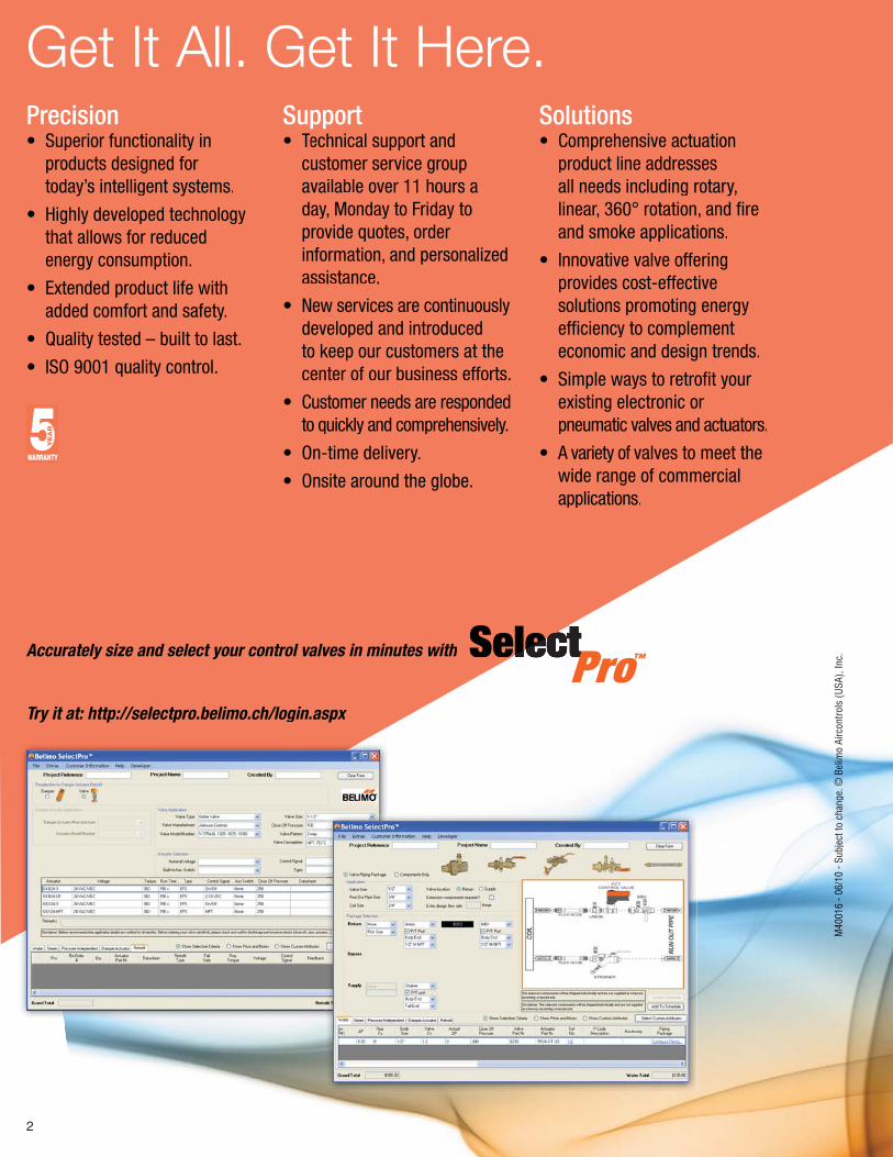
Get It All. Get It Here.Precision • Superior functionality in products designed for today’s intelligent systems.
• Highly developed technology that allows for reduced energy consumption.
• Extended product life with added comfort and safety.
• Quality tested – built to last.
• ISO 9001 quality control.
Support• Technical support and TT customer service group available over 11 hours a day, Monday to Friday to provide quotes, order information, and personalized assistance.
• New services are continuously developed and introduced to keep our customers at the center of our business efforts.
• Customer needs are responded to quickly and comprehensively.
• On-time delivery.
• Onsite around the globe.
Solutions• Comprehensive actuation product line addresses all needs including rotary, linear, 360° rotation, and fi re and smoke applications.
• Innovative valve offering provides cost-effective solutions promoting energy effi ciency to complement economic and design trends.
• Simple ways to retrofi t your existing electronic or pneumatic valves and actuators.
• A variety of valves to meet the wide range of commercial applications.
Accurately size and select your control valves in minutes with
Try it at: http://selectpro.belimo.ch/login.aspx
SelectPro™
000M
40M
404M
4M
4MMM
666661661010100- - - --
//6/060000 0 1001111
S S- - ub
jbjbjjec
tec
tee
tooot c
h c
hchchcan
gan
gan
ge. e.
B©
B©
BB©
©©©©©©
iiel
ielel
mo
mmmmmmmmmmmmmAi
rcon
trols
(USA
), In
c.
3
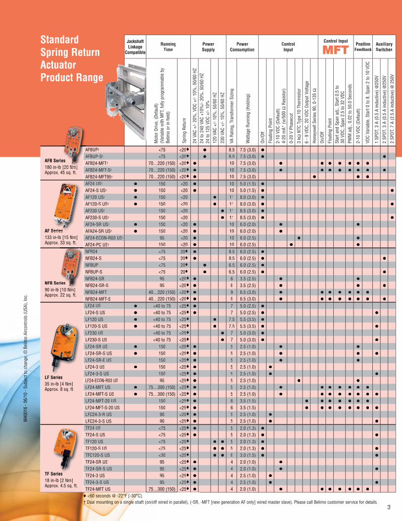
StandardSpring Return ActuatorProduct Range
Jackshaft Linkage
Compatible
RunningTime
PowerSupply
PowerConsumption
ControlInput
Control InputPosition
FeedbackAuxiliarySwitches
Mot
or D
rive,
(Def
ault)
(Var
iabl
e w
ith M
FT, f
ully
pro
gram
mab
le b
yBe
limo
or in
fiel
d)
Sprin
g Re
turn
24 V
AC +
/- 20
%, V
DC +
/- 10
%, 5
0/60
HZ
24 to
240
VAC
+10
%/-
20%
, 50/
60 H
Z24
to 1
25 V
DC +
/- 10
%12
0 VA
C +/
- 10%
, 50/
60 H
Z
230
VAC
+/- 1
0%, 5
0/60
HZ
VA R
atin
g, T
rans
form
er S
izing
Wat
tage
Run
ning
(Hol
ding
)
On/O
ff
Floa
ting
Poin
t
2-10
VDC
(Def
ault)
4-20
mA*
(w/5
00 Ω
Res
isto
r)
0-20
V P
hase
cut
3 kΩ
NTC
Typ
e 10
The
rmis
tor
6 - 9
VDC
, 20
VDC
Outp
ut V
olta
ge
Hone
ywel
l Ser
ies
90, 0
-135
Ω
On/O
ff
Floa
ting
Poin
tSt
art a
nd S
pan
adj.,
Sta
rt 0.
5 to
30 V
DC, S
pan
2.5
to 3
2 VD
C
PWM
adj
., 0.
02 to
50.
0 Se
cond
s
2-10
VDC
(Def
ault)
VDC
Varia
ble,
Sta
rt 0
to 8
, Spa
n 2
to 1
0 VD
C
1 SP
DT, 3
A (0
.5 A
indu
ctiv
e) @
250V
2 SP
DT, 3
A (0
.5 A
indu
ctiv
e) @
250V
2 SP
DT, 7
A (2
.5 A
indu
ctiv
e) @
250
V
AFB Seri180 in-lb [20 Nm] Approx. 45 sq. ft.
AFBUP† <75 <20♦ ● 8.5 7.5 (3.0) ●
AFBUP-S† <75 <20♦ ● 8.5 7.5 (3.0) ● ●
AFB24-MFT† 70…220 (150) <20♦ ● 10 7.5 (3.0) ● ● ● ● ● ● ●
AFB24-MFT-S† 70…220 (150) <20♦ ● 10 7.5 (3.0) ● ● ● ● ● ● ● ●
AFB24-MFT95† 70…220 (150) <20♦ ● 10 7.5 (3.0) ● ● ●
AF Series133 in-lb [15 Nm] Approx. 33 sq. ft.
AF24 US† ● 150 <20 ● 10 5.0 (1.5) ●
AF24-S US† ● 150 <20 ● 10 5.0 (1.5) ● ●
AF120 US† ● 150 <20 ● 11 8.0 (3.0) ●
AF120-S US† ● 150 <20 ● 11 8.0 (3.0) ● ●
AF230 US† 150 <20 ● 11 8.5 (3.0) ●
AF230-S US† 150 <20 ● 11 8.5 (3.0) ● ●
AF24-SR US† ● 150 <20 ● 10 6.0 (2.0) ● ●
AFA24-SR US† ● 150 <20 ● 10 6.0 (2.0) ●
AF24-ECON-R03 US† 95 <20 ● 10 6.0 (2.5) ● ●
AF24-PC US† 150 <20 ● 10 6.0 (2.5) ● ●
NFB Se90 in-lb [10 Nm]Approx. 22 sq. ft.
NFB24 <75 20♦ ● 8.5 6.0 (2.5) ●
NFB24-S <75 20♦ ● 8.5 6.0 (2.5) ● ●
NFBUP <75 20♦ ● 6.5 6.0 (2.5) ●
NFBUP-S <75 20♦ ● 6.5 6.0 (2.5) ● ●
NFB24-SR 95 <20♦ ● 6 3.5 (2.5) ● ●
NFB24-SR-S 95 <20♦ ● 6 3.5 (2.5) ● ● ●
NFB24-MFT 40…220 (150) <20♦ ● 9 6.5 (3.0) ● ● ● ● ● ● ●
NFB24-MFT-S 40…220 (150) <20♦ ● 9 6.5 (3.0) ● ● ● ● ● ● ● ●
LF Series35 in-lb [4 Nm]Approx. 8 sq. ft.
LF24 US ● <40 to 75 <25♦ ● 7 5.0 (2.5) ●
LF24-S US ● <40 to 75 <25♦ ● 7 5.0 (2.5) ● ●
LF120 US ● <40 to 75 <25♦ ● 7.5 5.5 (3.5) ●
LF120-S US ● <40 to 75 <25♦ ● 7.5 5.5 (3.5) ● ●
LF230 US <40 to 75 <25♦ ● 7 5.0 (3.0) ●
LF230-S US <40 to 75 <25♦ ● 7 5.0 (3.0) ● ●
LF24-SR US ● 150 <25♦ ● 5 2.5 (1.0) ● ●
LF24-SR-S US ● 150 <25♦ ● 5 2.5 (1.0) ● ● ●
LF24-SR-E US 150 <25♦ ● 5 2.5 (1.0) ● ●
LF24-3 US ● 150 <25♦ ● 5 2.5 (1.0) ●
LF24-3-S US 150 <25♦ ● 5 2.5 (1.0) ● ●
LF24-ECON-R03 US 95 <25♦ ● 5 2.5 (1.0) ● ●
LF24-MFT US ● 75…300 (150) <25♦ ● 5 2.5 (1.0) ● ● ● ● ● ● ●
LF24-MFT-S US ● 75…300 (150) <25♦ ● 5 2.5 (1.0) ● ● ● ● ● ● ● ●
LF24-MFT-20 US 150 <25♦ ● 6 3.5 (1.5) ● ● ● ● ● ● ●
LF24-MFT-S-20 US 150 <25♦ ● 6 3.5 (1.5) ● ● ● ● ● ● ● ●
LFC24-3-R US 90 <25♦ ● 5 2.5 (1.0) ●
LFC24-3-S US 90 <25♦ ● 5 2.5 (1.0) ● ●
TF Series18 in-lb [2 Nm]Approx. 4.5 sq. ft.
TF24 US <75 <25♦ ● 5 2.0 (1.3) ●
TF24-S US <75 <25♦ ● 5 2.0 (1.3) ● ●
TF120 US <75 <25♦ ● ● 5 2.0 (1.3) ●
TF120-S US <75 <25♦ ● ● 5 2.0 (1.3) ● ●
TFC120-S US <30 <25♦ ● ● 6 3.0 (1.5) ● ●
TF24-SR US 95 <25♦ ● 4 2.0 (1.0) ●
TF24-SR-S US 95 <25♦ ● 4 2.0 (1.0) ● ●
TF24-3 US 95 <25♦ ● 4 2.5 (1.0) ●
TF24-3-S US 95 <25♦ ● 4 2.5 (1.0) ● ●
TF24-MFT US 75…300 (150) <25♦ ● 4 2.0 (1.0) ● ● ● ● ● ● ●
♦♦♦♦♦♦♦♦♦ ♦ ♦♦♦♦♦ ♦♦♦♦♦♦♦♦♦♦♦ <60<60<60606060000600<600006 sese see seconcononnncoc ds dsds dsds @@ @ -@ --@ 22°22°22°22°°22°°2°2°22 FFFFFFFFF [F [FFFFFFF -30-30303030300000000000°°°°°°°C]°°°°°° . R, -MFT [new generation AF only] wired master slave). Please call Belimo customer service for details.†† D† D† D†† D†† D† D†††††† uuuuuuuaualuuuualuu mo moomountuntuntuntingingnging onononononnnnnnnnnnnnnn aaaaaaaa a a aaa aaa sinsinnnngleggglegleglgleglelegleglegleglggg shaft (on/off wired in parallel), (-SR
Series
S
Series
[10 Nm]erries
]
[20 Nm]
A A Aiees
m]
0M
404000M
4M
4MMMMMM
6160161010000
- - - - 06
/6/10
10
- S SS
ubj
ubjbjbjjjbjubjjbjjec
tec
tec
tec
tec
tec
tec
tec
tececececececee
otototo tototo toto c
h c
h c
ang
ange
. e.
e.
e.
e.
e.e.eB
© B
© B
iiiiilililieleo
mo
mmmmmmmmmmmmmmmmAi
rcon
trols
(USA
), In
c.
4
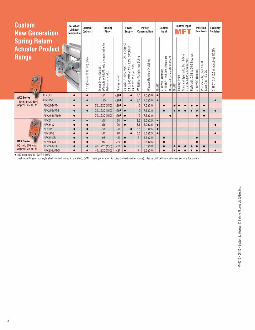
CustomNew GenerationSpring Return Actuator Product Range
Jackshaft Linkage
Compatible
CustomOptions
RunningTime
PowerSupply
PowerConsumption
ControlInput
Control InputPosition
FeedbackAuxiliarySwitches
10 ft
(3m
) or 1
6 ft
(5m
) cab
le
Mot
or D
rive,
(Def
ault)
(Var
iabl
e w
ith M
FT, f
ully
pro
gram
mab
le b
yBe
limo
or in
fiel
d)
Sprin
g Re
turn
24 V
AC +
/- 20
%, V
DC +
/- 10
%, 5
0/60
HZ
24 to
240
VAC
+10
%/-
20%
, 50/
60 H
Z24
to 1
25 V
DC +
/- 10
%
VA R
atin
g, T
rans
form
er S
izing
Wat
tage
Run
ning
(Hol
ding
)
On/O
ff2-
10 V
DC (D
efau
lt)4-
20 m
A* (w
/500
Ω R
esis
tor)
Hone
ywel
l Ser
ies
90, 0
-135
ΩOn
/Off
Floa
ting
Poin
tSt
art a
nd S
pan
adj.,
Sta
rt 0.
5 to
30 V
DC, S
pan
2.5
to 3
2 VD
C
PWM
adj
., 0.
02 to
50.
0 Se
cond
s
2-10
VDC
(Def
ault)
VDC
Varia
ble,
Sta
rt 0
to 8
,Sp
an 2
to 1
0 VD
C
2 SP
DT, 3
A (0
.5 A
indu
ctiv
e) @
250V
AFX Serie180 in-lb [20 Nm]Approx. 45 sq. ft.
AFXUP† ● ● <75 <20♦ ● 8.5 7.5 (3.0) ●
AFXUP-S† ● ● <75 <20♦ ● 8.5 7.5 (3.0) ● ●
AFX24-MFT† ● ● 70…220 (150) <20♦ ● 10 7.5 (3.0) ● ● ● ● ● ● ●
AFX24-MFT-S† ● ● 70…220 (150) <20♦ ● 10 7.5 (3.0) ● ● ● ● ● ● ● ●
AFX24-MFT95† ● 70…220 (150) <20♦ ● 10 7.5 (3.0) ● ● ●
NFX Ser90 in-lb [10 Nm]Approx. 22 sq. ft.
NFX24 ● ● <75 20 ● 8.5 6.0 (2.5) ●
NFX24-S ● ● <75 20 ● 8.5 6.0 (2.5) ● ●
NFXUP ● ● <75 20 ● 6.5 6.0 (2.5) ●
NFXUP-S ● ● <75 20 ● 6.5 6.0 (2.5) ● ●
NFX24-SR ● ● 95 <20 ● 6 3.5 (2.5) ● ●
NFX24-SR-S ● ● 95 <20 ● 6 3.5 (2.5) ● ● ●
NFX24-MFT ● ● 40…220 (150) <20 ● 9 6.5 (3.0) ● ● ● ● ● ● ●
NFX24-MFT-S ● ● 40…220 (150) <20 ● 9 6.5 (3.0) ● ● ● ● ● ● ● ●
♦ <60 seconds @ -22°F [-30°C].† Dual mounting on a single shaft (on/off wired in parallel), (-MFT [new generation AF only] wired master slave). Please call Belimo customer service for details.
[10 Nm]riies
es[20 N ]
A
Aees
M40
016
- 06/
10 -
Subj
ect t
o ch
ange
. © B
elim
o Ai
rcon
trols
(USA
), In
c.
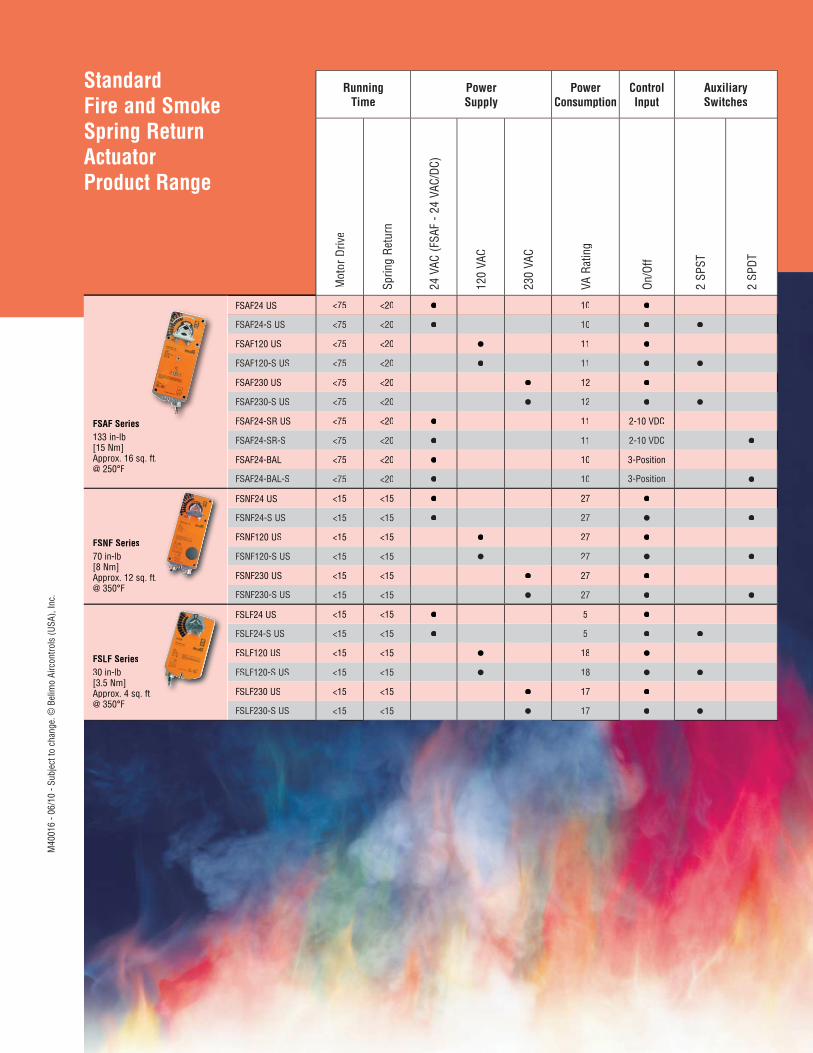
StandardFire and Smoke Spring Return ActuatorProduct Range
RunningTime
PowerSupply
PowerConsumption
ControlInput
AuxiliarySwitches
Mot
or D
rive
Sprin
g Re
turn
24 V
AC (F
SAF
- 24
VAC/
DC)
120
VAC
230
VAC
VA R
atin
g
On/O
ff
2 SP
ST
2 SP
DT
FSAF Series133 in-lb[15 Nm]Approx. 16 sq. ft.@ 250°F
FSAF24 US <75 <20 ● 10 ●
FSAF24-S US <75 <20 ● 10 ● ●
FSAF120 US <75 <20 ● 11 ●
FSAF120-S US <75 <20 ● 11 ● ●
FSAF230 US <75 <20 ● 12 ●
FSAF230-S US <75 <20 ● 12 ● ●
FSAF24-SR US <75 <20 ● 11 2-10 VDC
FSAF24-SR-S <75 <20 ● 11 2-10 VDC ●
FSAF24-BAL <75 <20 ● 10 3-Position
FSAF24-BAL-S <75 <20 ● 10 3-Position ●
FSNF Series70 in-lb[8 Nm]Approx. 12 sq. ft.@ 350°F
FSNF24 US <15 <15 ● 27 ●
FSNF24-S US <15 <15 ● 27 ● ●
FSNF120 US <15 <15 ● 27 ●
FSNF120-S US <15 <15 ● 27 ● ●
FSNF230 US <15 <15 ● 27 ●
FSNF230-S US <15 <15 ● 27 ● ●
FSLF Series30 in-lb[3.5 Nm]Approx. 4 sq. ft.@ 350°F
FSLF24 US <15 <15 ● 5 ●
FSLF24-S US <15 <15 ● 5 ● ●
FSLF120 US <15 <15 ● 18 ●
FSLF120-S US <15 <15 ● 18 ● ●
FSLF230 US <15 <15 ● 17 ●
FSLF230-S US <15 <15 ● 17 ● ●
M40
016
- 06/
10 -
Subj
ect t
o ch
ange
. © B
elim
o Ai
rcon
trols
(USA
), In
c.
6
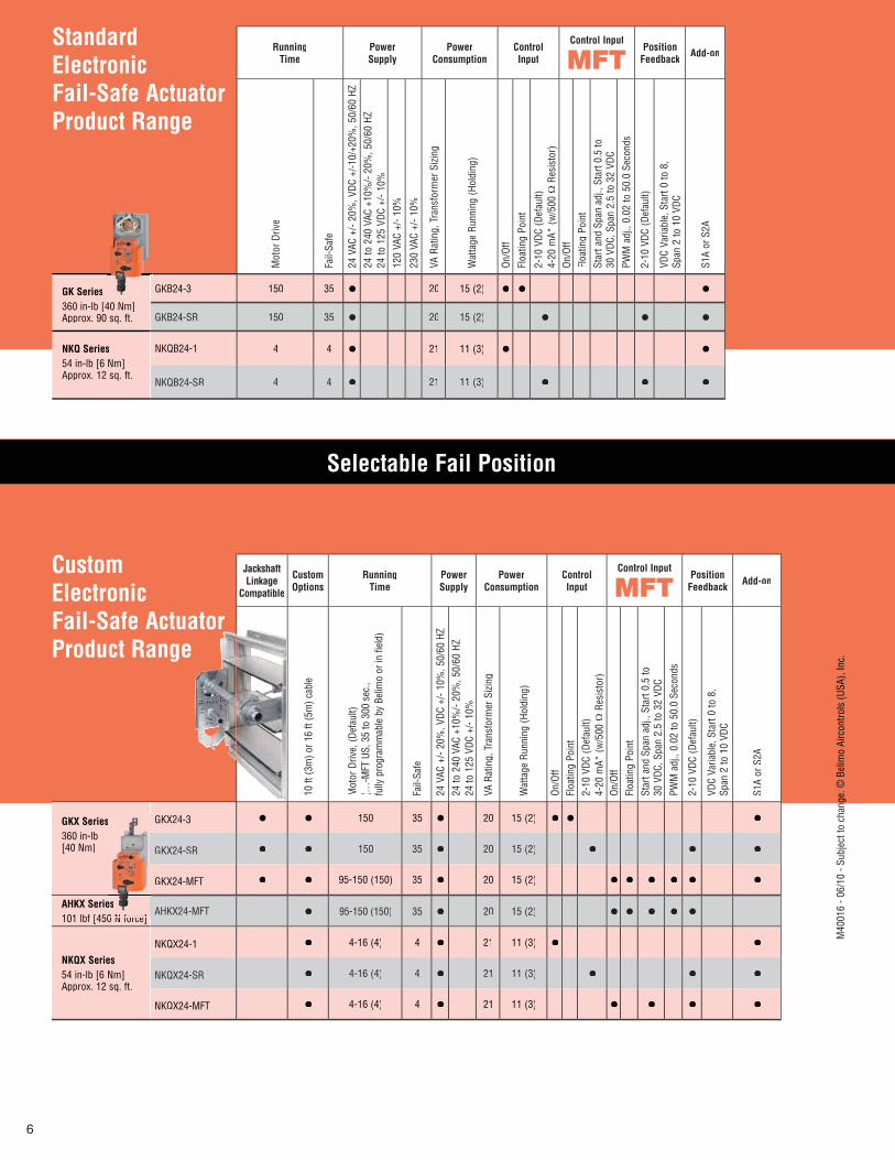
StandardElectronic Fail-Safe ActuatorProduct Range
RunningTime
PowerSupply
PowerConsumption
ControlInput
Control InputPosition
Feedback Add-on
Mot
or D
rive
Fail-
Safe
24 V
AC +
/- 20
%, V
DC +
/-10/
+20%
, 50/
60 H
Z24
to 2
40 V
AC +
10%
/- 20
%, 5
0/60
HZ
24 to
125
VDC
+/-
10%
120
VAC
+/- 1
0%
230
VAC
+/- 1
0%
VA R
atin
g, T
rans
form
er S
izing
Wat
tage
Run
ning
(Hol
ding
)
On/O
ff
Floa
ting
Poin
t
2-10
VDC
(Def
ault)
4-20
mA*
(w/5
00Ω
Res
isto
r)On
/Off
Floa
ting
Poin
tSt
art a
nd S
pan
adj.,
Sta
rt 0.
5 to
30 V
DC, S
pan
2.5
to 3
2 VD
C
PWM
adj
., 0.
02 to
50.
0 Se
cond
s
2-10
VDC
(Def
ault)
VDC
Varia
ble,
Sta
rt 0
to 8
,Sp
an 2
to 1
0 VD
C
S1A
or S
2A
GK Series360 in-lb [40 Nm]Approx. 90 sq. ft.
GKB24-3 150 35 ● 20 15 (2) ● ● ●
GKB24-SR 150 35 ● 20 15 (2) ● ● ●
NKQ Series54 in-lb [6 Nm]Approx. 12 sq. ft.
NKQB24-1 4 4 ● 21 11 (3) ● ●
NKQB24-SR 4 4 ● 21 11 (3) ● ● ●
CustomElectronic Fail-Safe Actuator Product Range
Jackshaft Linkage
Compatible
CustomOptions
RunningTime
PowerSupply
PowerConsumption
ControlInput
Control InputPosition
Feedback Add-on
10 ft
(3m
) or 1
6 ft
(5m
) cab
le
Mot
or D
rive,
(Def
ault)
(…-M
FT U
S, 3
5 to
300
sec
.,fu
lly p
rogr
amm
able
by
Belim
o or
in fi
eld)
Fail-
Safe
24 V
AC +
/- 20
%, V
DC +
/- 10
%, 5
0/60
HZ
24 to
240
VAC
+10
%/-
20%
, 50/
60 H
Z24
to 1
25 V
DC +
/- 10
%
VA R
atin
g, T
rans
form
er S
izing
Wat
tage
Run
ning
(Hol
ding
)
On/O
ffFl
oatin
g Po
int
2-10
VDC
(Def
ault)
4-20
mA*
(w/5
00 Ω
Res
isto
r)On
/Off
Floa
ting
Poin
tSt
art a
nd S
pan
adj.,
Sta
rt 0.
5 to
30 V
DC, S
pan
2.5
to 3
2 VD
C
PWM
adj
., 0.
02 to
50.
0 Se
cond
s
2-10
VDC
(Def
ault)
VDC
Varia
ble,
Sta
rt 0
to 8
,Sp
an 2
to 1
0 VD
C
S1A
or S
2A
GKX Series360 in-lb[40 Nm]
GKX24-3 ● ● 150 35 ● 20 15 (2) ● ● ●
GKX24-SR ● ● 150 35 ● 20 15 (2) ● ● ●
GKX24-MFT ● ● 95-150 (150) 35 ● 20 15 (2) ● ● ● ● ● ●
AHKX Serie101 lbf [450 N force]
AHKX24-MFT ● 95-150 (150) 35 ● 20 15 (2) ● ● ● ● ●
NKQX Series54 in-lb [6 Nm]Approx. 12 sq. ft.
NKQX24-1 ● 4-16 (4) 4 ● 21 11 (3) ● ●
NKQX24-SR ● 4-16 (4) 4 ● 21 11 (3) ● ● ●
NKQX24-MFT ● 4-16 (4) 4 ● 21 11 (3) ● ● ● ●
Selectable Fail Position
s
es0 N force]
M40
016
- 06/
10 -
Subj
ect t
o ch
ange
. © B
elim
o Ai
rcon
trols
(USA
), In
c.
7
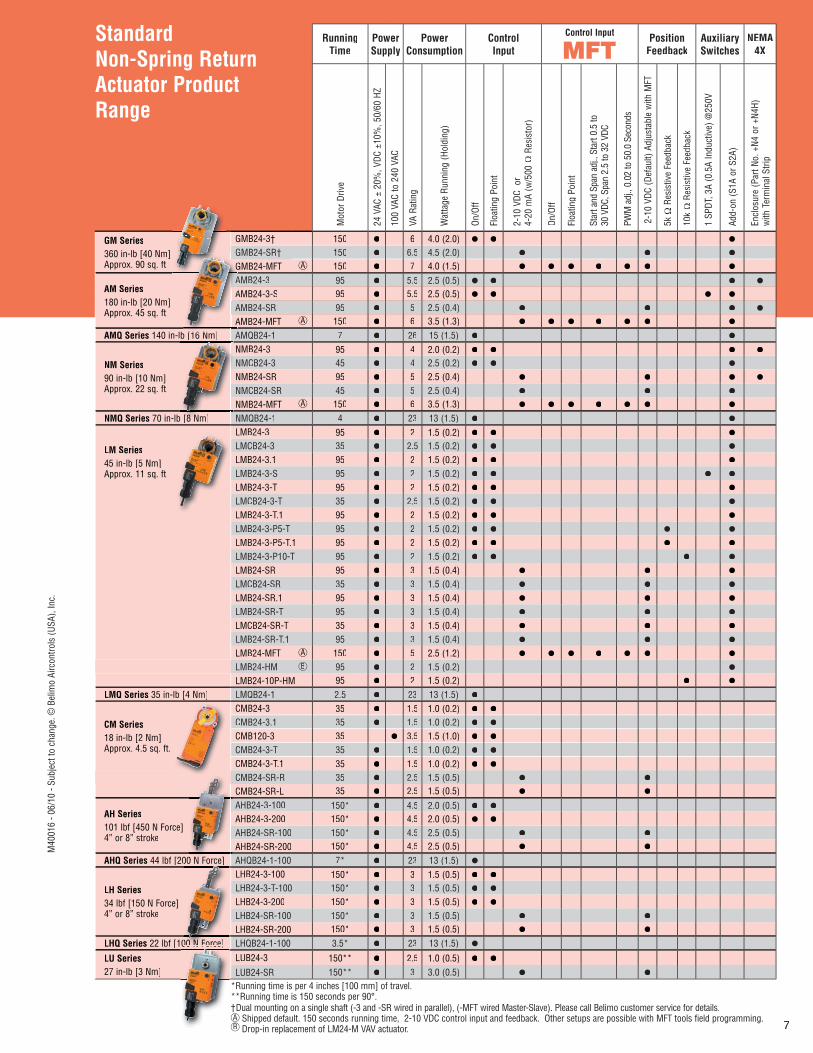
Standard Non-Spring Return Actuator Product Range
RunningTime
PowerSupply
PowerConsumption
ControlInput
Control Input Position Feedback
AuxiliarySwitches
NEMA4X
Mot
or D
rive
24 V
AC ±
20%
, VDC
±10
%, 5
0/60
HZ
100
VAC
to 2
40 V
AC
VA R
atin
g
Wat
tage
Run
ning
(Hol
ding
)
On/O
ff
Floa
ting
Poin
t
2-10
VDC
or
4-20
mA
(w/5
00 Ω
Res
isto
r)
On/O
ff
Floa
ting
Poin
t
Star
t and
Spa
n ad
j., S
tart
0.5
to30
VDC
, Spa
n 2.
5 to
32
VDC
PWM
adj
., 0.
02 to
50.
0 Se
cond
s
2-1
0 VD
C (D
efau
lt) A
djus
tabl
e w
ith M
FT
5kΩ
Res
istiv
e Fe
edba
ck
10k
Ω R
esis
tive
Feed
back
1 SP
DT, 3
A (0
.5A
Indu
ctiv
e) @
250V
Add-
on (S
1A o
r S2A
)
Encl
osur
e (P
art N
o. +
N4 o
r +N4
H)w
ith T
erm
inal
Stri
p
GM Series360 in-lb [40 Nm]Approx. 90 sq. ft.
GMB24-3† 150 ● 6 4.0 (2.0) ● ● ●
GMB24-SR† 150 ● 6.5 4.5 (2.0) ● ● ●
GMB24-MFT AA 150 ● 7 4.0 (1.5) ● ● ● ● ● ● ●
AM Series180 in-lb [20 Nm]Approx. 45 sq. ft.
AMB24-3 95 ● 5.5 2.5 (0.5) ● ● ● ●
AMB24-3-S 95 ● 5.5 2.5 (0.5) ● ● ● ●
AMB24-SR 95 ● 5 2.5 (0.4) ● ● ● ●
AMB24-MFT AA 150 ● 6 3.5 (1.3) ● ● ● ● ● ● ●
AMQ Series 140 in-lb [16 Nm] AMQB24-1 7 ● 26 15 (1.5) ● ●
NM Series90 in-lb [10 Nm]Approx. 22 sq. ft.
NMB24-3 95 ● 4 2.0 (0.2) ● ● ● ●
NMCB24-3 45 ● 4 2.5 (0.2) ● ● ●
NMB24-SR 95 ● 5 2.5 (0.4) ● ● ● ●
NMCB24-SR 45 ● 5 2.5 (0.4) ● ● ●
NMB24-MFT AA 150 ● 6 3.5 (1.3) ● ● ● ● ● ● ●
NMQ Series 70 in-lb [8 Nm] NMQB24-1 4 ● 23 13 (1.5) ● ●
LM Series45 in-lb [5 Nm]Approx. 11 sq. ft.
LMB24-3 95 ● 2 1.5 (0.2) ● ● ●
LMCB24-3 35 ● 2.5 1.5 (0.2) ● ● ●
LMB24-3.1 95 ● 2 1.5 (0.2) ● ● ●
LMB24-3-S 95 ● 2 1.5 (0.2) ● ● ● ●
LMB24-3-T 95 ● 2 1.5 (0.2) ● ● ●
LMCB24-3-T 35 ● 2.5 1.5 (0.2) ● ● ●
LMB24-3-T.1 95 ● 2 1.5 (0.2) ● ● ●
LMB24-3-P5-T 95 ● 2 1.5 (0.2) ● ● ● ●
LMB24-3-P5-T.1 95 ● 2 1.5 (0.2) ● ● ● ●
LMB24-3-P10-T 95 ● 2 1.5 (0.2) ● ● ● ●
LMB24-SR 95 ● 3 1.5 (0.4) ● ● ●
LMCB24-SR 35 ● 3 1.5 (0.4) ● ● ●
LMB24-SR.1 95 ● 3 1.5 (0.4) ● ● ●
LMB24-SR-T 95 ● 3 1.5 (0.4) ● ● ●
LMCB24-SR-T 35 ● 3 1.5 (0.4) ● ● ●
LMB24-SR-T.1 95 ● 3 1.5 (0.4) ● ● ●
LMB24-MFT AA 150 ● 5 2.5 (1.2) ● ● ● ● ● ● ●
LMB24-HM B 95 ● 2 1.5 (0.2) ●
LMB24-10P-HM 95 ● 2 1.5 (0.2) ● ●
LMQ Series 35 in-lb [4 Nm] LMQB24-1 2.5 ● 23 13 (1.5) ●
CM Series18 in-lb [2 Nm]Approx. 4.5 sq. ft.
CMB24-3 35 ● 1.5 1.0 (0.2) ● ●
CMB24-3.1 35 ● 1.5 1.0 (0.2) ● ●
CMB120-3 35 ● 3.5 1.5 (1.0) ● ●
CMB24-3-T 35 ● 1.5 1.0 (0.2) ● ●
CMB24-3-T.1 35 ● 1.5 1.0 (0.2) ● ●
CMB24-SR-R 35 ● 2.5 1.5 (0.5) ● ●
CMB24-SR-L 35 ● 2.5 1.5 (0.5) ● ●
AH Series101 lbf [450 N Force] 4” or 8” stroke
AHB24-3-100 150* ● 4.5 2.0 (0.5) ● ●
AHB24-3-200 150* ● 4.5 2.0 (0.5) ● ●
AHB24-SR-100 150* ● 4.5 2.5 (0.5) ● ●
AHB24-SR-200 150* ● 4.5 2.5 (0.5) ● ●
AHQ Series 44 lbf [200 N Force] AHQB24-1-100 7* ● 23 13 (1.5) ●
LH Series34 lbf [150 N Force] 4” or 8” stroke
LHB24-3-100 150* ● 3 1.5 (0.5) ● ●
LHB24-3-T-100 150* ● 3 1.5 (0.5) ● ●
LHB24-3-200 150* ● 3 1.5 (0.5) ● ●
LHB24-SR-100 150* ● 3 1.5 (0.5) ● ●
LHB24-SR-200 150* ● 3 1.5 (0.5) ● ●
LHQ Series 22 lbf [100 N Force] LHQB24-1-100 3.5* ● 23 13 (1.5) ●
LU Series27 in-lb [3 Nm]
LUB24-3 150** ● 2.5 1.0 (0.5) ● ●
LUB24-SR 150** ● 3 3.0 (0.5) ● ●
*Running time is per 4 inches [100 mm] of travel. **Running time is 150 seconds per 90°.† Dual mounting on a single shaft (-3 and -SR wired in parallel), (-MFT wired Master-Slave). Please call Belimo customer service for details.
Shipped default. 150 seconds running time, 2-10 VDC control input and feedback. Other setups are possible with MFT tools field programming.B Drop-in replacement of LM24-M VAV actuator.
b [16 Nm]
b [8 Nm]
0 N F ]00 N Force]
00 N Force]00 N Force]
G G A A A A
b [16 N ] A
M40
016
- 06/
10 -
Subj
ect t
o ch
ange
. © B
elim
o Ai
rcon
trols
(USA
), In
c.
8
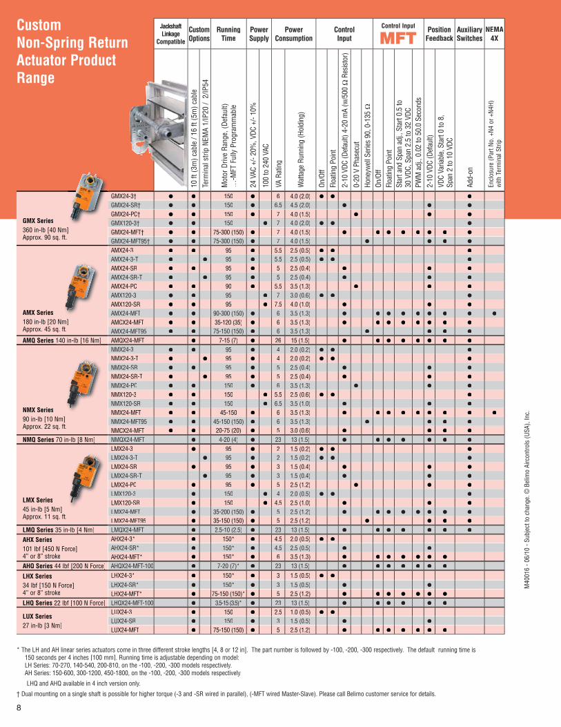
Custom Non-Spring ReturnActuator Product Range
JackshaftLinkage
Compatible
CustomOptions
RunningTime
PowerSupply
PowerConsumption
ControlInput
Control Input PositionFeedback
AuxiliarySwitches
NEMA4X
10 ft
(3m
) cab
le /
16 ft
(5m
) cab
le
Term
inal
stri
p NE
MA
1/IP
20 /
2/IP
54
Mot
or D
rive
Rang
e, (D
efau
lt)…
-MFT
Ful
ly P
rogr
amm
able
24 V
AC +
/- 20
%, V
DC +
/- 10
%
100
to 2
40 V
AC
VA R
atin
g
Wat
tage
Run
ning
(Hol
ding
)
On/O
ffFl
oatin
g Po
int
2-10
VDC
(Def
ault)
4-2
0 m
A (w
/500
ΩRe
sist
or)
0-20
V P
hase
cut
Hone
ywel
l Ser
ies
90, 0
-135
ΩOn
/Off
Floa
ting
Poin
tSt
art a
nd S
pan
adj.,
Sta
rt 0.
5 to
30 V
DC, S
pan
2.5
to 3
2 VD
CPW
M a
dj.,
0.02
to 5
0.0
Seco
nds
2-10
VDC
(Def
ault)
VDC
Varia
ble,
Sta
rt 0
to 8
,Sp
an 2
to 1
0 VD
C
Add-
on
Encl
osur
e (P
art N
o. +
N4 o
r +N4
H)w
ith T
erm
inal
Stri
p
GMX Series360 in-lb [40 Nm]Approx. 90 sq. ft.
GMX24-3† ● ● 150 ● 6 4.0 (2.0) ● ● ●
GMX24-SR† ● ● 150 ● 6.5 4.5 (2.0) ● ● ●
GMX24-PC† ● ● 150 ● 7 4.0 (1.5) ● ● ●
GMX120-3† ● ● 150 ● 7 4.0 (2.0) ● ● ●
GMX24-MFT† ● ● 75-300 (150) ● 7 4.0 (1.5) ● ● ● ● ● ● ● ●
GMX24-MFT95† ● ● 75-300 (150) ● 7 4.0 (1.5) ● ● ● ●
AMX Series180 in-lb [20 Nm]Approx. 45 sq. ft.
AMX24-3 ● ● 95 ● 5.5 2.5 (0.5) ● ● ●
AMX24-3-T ● ● 95 ● 5.5 2.5 (0.5) ● ● ●
AMX24-SR ● ● 95 ● 5 2.5 (0.4) ● ● ●
AMX24-SR-T ● ● 95 ● 5 2.5 (0.4) ● ● ●
AMX24-PC ● ● 90 ● 5.5 3.5 (1.3) ● ● ●
AMX120-3 ● ● 95 ● 7 3.0 (0.6) ● ● ●
AMX120-SR ● ● 95 ● 7.5 4.0 (1.0) ● ● ●
AMX24-MFT ● ● 90-300 (150) ● 6 3.5 (1.3) ● ● ● ● ● ● ● ● ●
AMCX24-MFT ● ● 35-120 (35) ● 6 3.5 (1.3) ● ● ● ● ● ● ● ●
AMX24-MFT95 ● ● 75-150 (150) ● 6 3.5 (1.3) ● ● ● ●
AMQ Series 140 in-lb [16 Nm] AMQX24-MFT ● 7-15 (7) ● 26 15 (1.5) ● ● ● ● ● ● ● ●
NMX Series90 in-lb [10 Nm]Approx. 22 sq. ft.
NMX24-3 ● ● 95 ● 4 2.0 (0.2) ● ● ●
NMX24-3-T ● ● 95 ● 4 2.0 (0.2) ● ● ●
NMX24-SR ● ● 95 ● 5 2.5 (0.4) ● ● ●
NMX24-SR-T ● ● 95 ● 5 2.5 (0.4) ● ● ●
NMX24-PC ● ● 150 ● 6 3.5 (1.3) ● ● ●
NMX120-3 ● ● 150 ● 5.5 2.5 (0.6) ● ● ●
NMX120-SR ● ● 150 ● 6.5 3.5 (1.0) ● ● ●
NMX24-MFT ● ● 45-150 ● 6 3.5 (1.3) ● ● ● ● ● ● ● ● ●
NMX24-MFT95 ● ● 45-150 (150) ● 6 3.5 (1.3) ● ● ● ●
NMCX24-MFT ● ● 20-75 (20) ● 5 3.0 (0.6) ● ● ● ●
NMQ Series 70 in-lb [8 Nm] NMQX24-MFT ● 4-20 (4) ● 23 13 (1.5) ● ● ● ● ● ● ●
LMX Series45 in-lb [5 Nm]Approx. 11 sq. ft.
LMX24-3 ● 95 ● 2 1.5 (0.2) ● ● ●
LMX24-3-T ● 95 ● 2 1.5 (0.2) ● ● ●
LMX24-SR ● 95 ● 3 1.5 (0.4) ● ● ●
LMX24-SR-T ● 95 ● 3 1.5 (0.4) ● ● ●
LMX24-PC ● 95 ● 5 2.5 (1.2) ● ● ●
LMX120-3 ● 150 ● 4 2.0 (0.5) ● ● ●
LMX120-SR ● 150 ● 4.5 2.5 (1.0) ● ● ●
LMX24-MFT ● 35-200 (150) ● 5 2.5 (1.2) ● ● ● ● ● ● ● ●
LMX24-MFT95 ● 35-150 (150) ● 5 2.5 (1.2) ● ● ● ●
LMQ Series 35 in-lb [4 Nm] LMQX24-MFT ● 2.5-10 (2.5) ● 23 13 (1.5) ● ● ● ● ● ● ●
AHX Series101 lbf [450 N Force]4” or 8” stroke
AHX24-3* ● 150* ● 4.5 2.0 (0.5) ● ●
AHX24-SR* ● 150* ● 4.5 2.5 (0.5) ● ●
AHX24-MFT* ● 150* ● 6 3.5 (1.3) ● ● ● ● ● ● ●
AHQ Series 44 lbf [200 N Force] AHQX24-MFT-100 ● 7-20 (7)* ● 23 13 (1.5) ● ● ● ● ● ● ●
LHX Series34 lbf [150 N Force]4” or 8” stroke
LHX24-3* ● 150* ● 3 1.5 (0.5) ● ●
LHX24-SR* ● 150* ● 3 1.5 (0.5) ● ●
LHX24-MFT* ● 75-150 (150)* ● 5 2.5 (1.2) ● ● ● ● ● ● ●
LHQ Series 22 lbf [100 N Force] LHQX24-MFT-100 ● 3.5-15 (3.5)* ● 23 13 (1.5) ● ● ● ● ● ●
LUX Series27 in-lb [3 Nm]
LUX24-3 ● 150 ● 2.5 1.0 (0.5) ● ●
LUX24-SR ● 150 ● 3 1.5 (0.5) ● ●
LUX24-MFT ● 75-150 (150) ● 5 2.5 (1.2) ● ● ● ● ● ● ●
* The LH and AH linear series actuators come in three different stroke lengths [4, 8 or 12 in]. The part number is followed by -100, -200, -300 respectively. The default running time is150 seconds per 4 inches [100 mm]. Running time is adjustable depending on model:LH Series: 70-270, 140-540, 200-810, on the -100, -200, -300 models respectively.AH Series: 150-600, 300-1200, 450-1800, on the -100, -200, -300 models respectively.
LHQ and AHQ available in 4 inch version only.
† Dual mounting on a single shaft is possible for higher torque (-3 and -SR wired in parallel), (-MFT wired Master-Slave). Please call Belimo customer service for details.
M40
016
- 06/
10 -
Subj
ect t
o ch
ange
. © B
elim
o Ai
rcon
trols
(USA
), In
c.
9
Control Valve Product Range
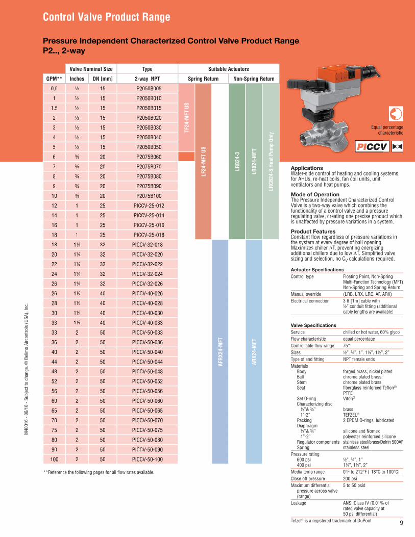
ApplicationsWater-side control of heating and cooling systems, for AHUs, re-heat coils, fan coil units, unitventilators and heat pumps.
Mode of OperationThe Pressure Independent Characterized Control Valve is a two-way valve which combines thefunctionality of a control valve and a pressureregulating valve, creating one precise product whichis unaffected by pressure variations in a system.
Product FeaturesConstant fl ow regardless of pressure variations inthe system at every degree of ball opening.Maximizes chiller ΔT, preventing energizingadditional chillers due to low ΔT. Simplifi ed valve sizing and selection, no Cv calculations required.
Actuator Specifi cationsControl type Floating Point, Non-Spring Multi-Function Technology (MFT) Non-Spring and Spring ReturnManual override (LRB, LRX, LRC, AF, ARX)Electrical connection 3 ft [1m] cable with ½” conduit fi tting (additional cable lengths are available)
Valve Specifi cationsService chilled or hot water, 60% glycolFlow characteristic equal percentageControllable fl ow range 75°Sizes ½”, ¾”, 1”, 1¼”, 1½”, 2”Type of end fi tting NPT female endsMaterials Body forged brass, nickel plated Ball chrome plated brass Stem chrome plated brass Seat fi berglass reinforced Tefl on® PTFE Set O-ring Viton® Characterizing disc ½”& ¾” brass 1”-2” TEFZEL® Packing 2 EPDM O-rings, lubricated Diaphragm ½”& ¾” silicone and Nomex 1”-2” polyester reinforced silicone Regulator components stainless steel/brass/Delrin 500AF Spring stainless steelPressure rating 600 psi ½”, ¾”, 1” 400 psi 1¼”, 1½”, 2” Media temp range 0°F to 212°F [-18°C to 100°C]Close off pressure 200 psi Maximum differential 5 to 50 psid pressure across valve (range)Leakage ANSI Class IV (0.01% of rated valve capacity at 50 psi differential)Tefzel® is a registered trademark of DuPont
Valve Nominal Size Type Suitable Actuators
GPM** Inches DN [mm] 2-way NPT Spring Return Non-Spring Return
0.5 ½ 15 P2050B005
TF24
-MFT
US
LF24
-MFT
US
LRB2
4-3
LRX2
4-M
FT
LRCB
24-3
Hea
t Pum
p On
ly
1 ½ 15 P2050B010
1.5 ½ 15 P2050B015
2 ½ 15 P2050B020
3 ½ 15 P2050B030
4 ½ 15 P2050B040
5 ½ 15 P2050B050
6 ¾ 20 P2075B060
7 ¾ 20 P2075B070
8 ¾ 20 P2075B080
9 ¾ 20 P2075B090
10 ¾ 20 P2075B100
12 1 25 PICCV-25-012
14 1 25 PICCV-25-014
16 1 25 PICCV-25-016
18 1 25 PICCV-25-018
18 1¼ 32 PICCV-32-018
AFRX
24-M
FT
ARX2
4-M
FT20 1¼ 32 PICCV-32-020
22 1¼ 32 PICCV-32-022
24 1¼ 32 PICCV-32-024
26 1¼ 32 PICCV-32-026
26 1½ 40 PICCV-40-026
28 1½ 40 PICCV-40-028
30 1½ 40 PICCV-40-030
33 1½ 40 PICCV-40-033
33 2 50 PICCV-50-033
36 2 50 PICCV-50-036
40 2 50 PICCV-50-040
44 2 50 PICCV-50-044
48 2 50 PICCV-50-048
52 2 50 PICCV-50-052
56 2 50 PICCV-50-056
60 2 50 PICCV-50-060
65 2 50 PICCV-50-065
70 2 50 PICCV-50-070
75 2 50 PICCV-50-075
80 2 50 PICCV-50-080
90 2 50 PICCV-50-090
100 2 50 PICCV-50-100
**Reference the following pages for all fl ow rates available.
Pressure Independent Characterized Control Valve Product Range P2.., 2-way
PI V
percentagearacteristic
PICCV
Equal cha
M40
016
- 06/
10 -
Subj
ect t
o ch
ange
. © B
elim
o Ai
rcon
trols
(USA
), In
c.
10
Control Valve Product Range
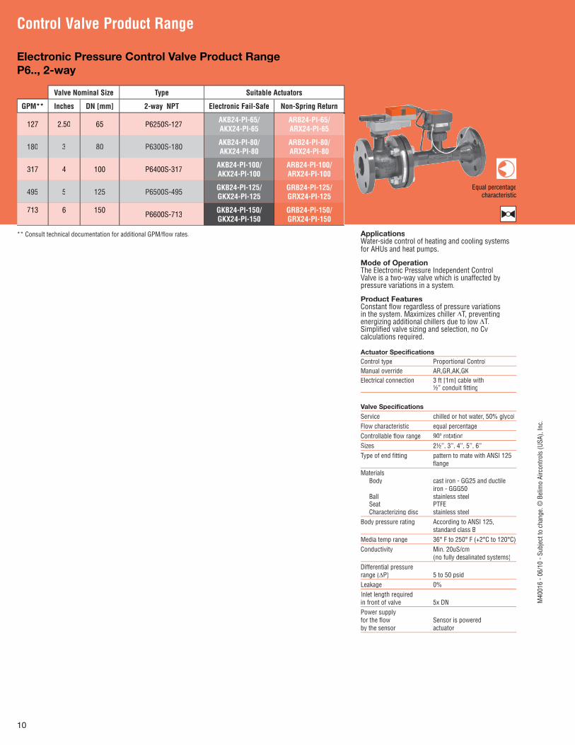
ApplicationsWater-side control of heating and cooling systemsfor AHUs and heat pumps.
Mode of OperationThe Electronic Pressure Independent ControlValve is a two-way valve which is unaffected bypressure variations in a system.
Product FeaturesConstant fl ow regardless of pressure variationsin the system. Maximizes chiller ΔT, preventing energizing additional chillers due to low ΔT.Simplifi ed valve sizing and selection, no Cvcalculations required.
Actuator Specifi cationsControl type Proportional ControlManual override AR,GR,AK,GKElectrical connection 3 ft [1m] cable with ½” conduit fi tting
Valve Specifi cationsService chilled or hot water, 50% glycolFlow characteristic equal percentageControllable fl ow range 90º rotationSizes 2½’’, 3’’, 4’’, 5’’, 6’’Type of end fi tting pattern to mate with ANSI 125 fl angeMaterials Body cast iron - GG25 and ductile iron - GGG50 Ball stainless steel Seat PTFE Characterizing disc stainless steelBody pressure rating According to ANSI 125, standard class BMedia temp range 36° F to 250° F (+2°C to 120°C)Conductivity Min. 20uS/cm (no fully desalinated systems)Differential pressure range (ΔP) 5 to 50 psidLeakage 0%Inlet length required in front of valve 5x DNPower supply for the fl ow Sensor is powered by the sensor actuator
Valve Nominal Size Type Suitable Actuators
GPM** Inches DN [mm] 2-way NPT Electronic Fail-Safe Non-Spring Return
127 2.50 65 P6250S-127 AKB24-PI-65/AKX24-PI-65
ARB24-PI-65/ARX24-PI-65
180 3 80 P6300S-180 AKB24-PI-80/AKX24-PI-80
ARB24-PI-80/ARX24-PI-80
317 4 100 P6400S-317 AKB24-PI-100/AKX24-PI-100
ARB24-PI-100/ARX24-PI-100
495 5 125 P6500S-495 GKB24-PI-125/GKX24-PI-125
GRB24-PI-125/GRX24-PI-125
713 6 150 P6600S-713 GKB24-PI-150/GKX24-PI-150
GRB24-PI-150/GRX24-PI-150
Electronic Pressure Control Valve Product Range P6.., 2-way
Equal percentagecharacteristic
** Consult technical documentation for additional GPM/fl ow rates.
M40
016
- 06/
10 -
Subj
ect t
o ch
ange
. © B
elim
o Ai
rcon
trols
(USA
), In
c.
11
Control Valve Product Range
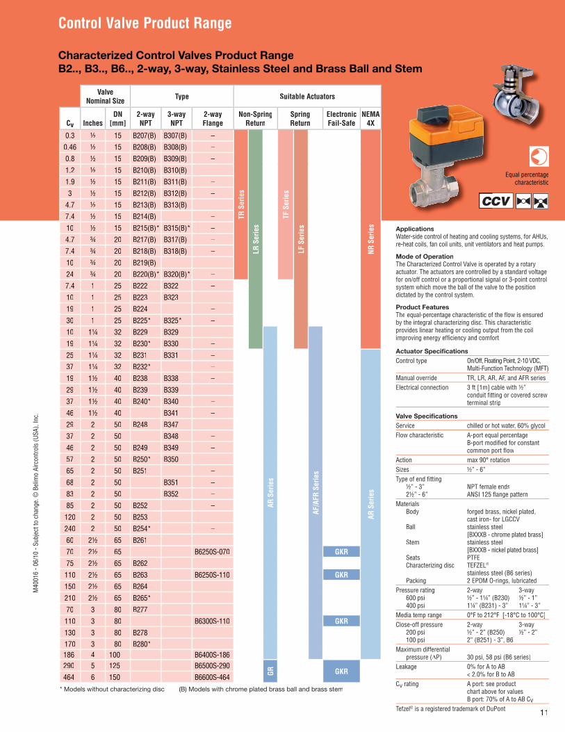
Characterized Control Valves Product RangeB2.., B3.., B6.., 2-way, 3-way, Stainless Steel and Brass Ball and Stem
CV
Equal percentagecharacteristic
ApplicationsWater-side control of heating and cooling systems, for AHUs, re-heat coils, fan coil units, unit ventilators and heat pumps.
Mode of OperationThe Characterized Control Valve is operated by a rotary actuator. The actuators are controlled by a standard voltagefor on/off control or a proportional signal or 3-point controlsystem which move the ball of the valve to the positiondictated by the control system.
Product FeaturesThe equal-percentage characteristic of the fl ow is ensuredby the integral characterizing disc. This characteristicprovides linear heating or cooling output from the coilimproving energy effi ciency and comfort.
Actuator Specifi cationsControl type On/Off, Floating Point, 2-10 VDC, Multi-Function Technology (MFT)Manual override TR, LR, AR, AF, and AFR seriesElectrical connection 3 ft [1m] cable with ½” conduit fi tting or covered screw terminal strip
Valve Specifi cationsService chilled or hot water, 60% glycolFlow characteristic A-port equal percentage B-port modifi ed for constant common port fl owAction max 90° rotationSizes ½” - 6”Type of end fi tting ½” - 3” NPT female ends 2½” - 6” ANSI 125 fl ange patternMaterials Body forged brass, nickel plated, cast iron- for LGCCV Ball stainless steel [BXXXB - chrome plated brass] Stem stainless steel [BXXXB - nickel plated brass] Seats PTFE Characterizing disc TEFZEL® stainless steel (B6 series) Packing 2 EPDM O-rings, lubricatedPressure rating 2-way 3-way 600 psi ½” - 1¼” (B230) ½” - 1” 400 psi 1¼” (B231) - 3” 1¼” - 3”Media temp range 0°F to 212°F [-18°C to 100°C]Close-off pressure 2-way 3-way 200 psi ½” - 2” (B250) ½” - 2” 100 psi 2” (B251) - 3”, B6Maximum differential pressure (ΔP) 30 psi, 58 psi (B6 series)Leakage 0% for A to AB < 2.0% for B to ABCv rating A port: see product chart above for values B port: 70% of A to AB CvTefzel® is a registered trademark of DuPont
ValveNominal Size Type Suitable Actuators
Cv InchesDN
[mm]2-wayNPT
3-wayNPT
2-wayFlange
Non-SpringReturn
Spring Return
ElectronicFail-Safe
NEMA 4X
0.3 ½ 15 B207(B) B307(B) –
TR S
erie
s
LR S
erie
s
TF S
erie
s
LF S
erie
s
NR S
erie
s
0.46 ½ 15 B208(B) B308(B) –
0.8 ½ 15 B209(B) B309(B) –
1.2 ½ 15 B210(B) B310(B) –
1.9 ½ 15 B211(B) B311(B) –
3 ½ 15 B212(B) B312(B) –
4.7 ½ 15 B213(B) B313(B) –
7.4 ½ 15 B214(B) –
10 ½ 15 B215(B)* B315(B)* –
4.7 ¾ 20 B217(B) B317(B) –
7.4 ¾ 20 B218(B) B318(B) –
10 ¾ 20 B219(B) –
24 ¾ 20 B220(B)* B320(B)* –
7.4 1 25 B222 B322 –
10 1 25 B223 B323 –
19 1 25 B224 –
30 1 25 B225* B325* –
10 1¼ 32 B229 B329 –
AR S
erie
s
AF/A
FR S
erie
s
19 1¼ 32 B230* B330 –
25 1¼ 32 B231 B331 –
AR S
erie
s37 1¼ 32 B232* –
19 1½ 40 B238 B338 –
29 1½ 40 B239 B339 –
37 1½ 40 B240* B340 –
46 1½ 40 B341 –
29 2 50 B248 B347 –
37 2 50 B348 –
46 2 50 B249 B349 –
57 2 50 B250* B350 –
65 2 50 B251 –
68 2 50 B351 –
83 2 50 B352 –
85 2 50 B252 –
120 2 50 B253 –
240 2 50 B254* –
60 2½ 65 B261
70 2½ 65 B6250S-070 GKR
75 2½ 65 B262
110 2½ 65 B263 B6250S-110 GKR
150 2½ 65 B264
210 2½ 65 B265*
70 3 80 B277
110 3 80 B6300S-110 GKR
130 3 80 B278170 3 80 B280*186 4 100 B6400S-186290 5 125 B6500S-290
GR GKR464 6 150 B6600S-464
* Models without characterizing disc (B) Models with chrome plated brass ball and brass stem
CC
M40
016
- 06/
10 -
Subj
ect t
o ch
ange
. © B
elim
o Ai
rcon
trols
(USA
), In
c.
12
Control Valve Product Range
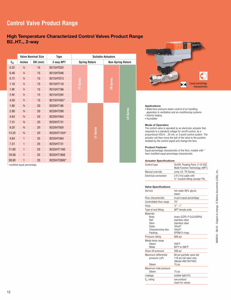
High Temperature Characterized Control Valves Product RangeB2..HT.., 2-way
eEqual percentageccharacteristic
Valve Nominal Size Type Suitable Actuators
Cv Inches DN [mm] 2-way NPT Spring Return Non-Spring Return
0.29 ½ 15 B215HT029
TF S
erie
s
TR S
erie
s
LR S
erie
s
0.46 ½ 15 B215HT046
0.73 ½ 15 B215HT073
1.16 ½ 15 B215HT116
1.86 ½ 15 B215HT186
2.90 ½ 15 B215HT290
4.55 ½ 15 B215HT455*
1.86 ¾ 20 B220HT186
LF S
erie
s
2.90 ¾ 20 B220HT290
4.64 ¾ 20 B220HT464
7.31 ¾ 20 B220HT731
9.28 ¾ 20 B220HT928
13.20 ¾ 20 B220HT1320*
4.64 1 25 B225HT464
7.31 1 25 B225HT731
11.60 1 25 B225HT1160
18.56 1 25 B225HT1856
28.00 1 25 B225HT2800** modifi ed equal percentage.
Actuator Specifi cationsControl type On/Off, Floating Point, 2-10 VDC Multi-Function Technology (MFT)Manual override (only LR, TR Series)Electrical connection 3 ft [1m] cable with ½” conduit fi tting (except TR)
Valve Specifi cationsService hot water 60% glycol, steamFlow characteristic A-port equal percentageControllable fl ow range 75°Sizes ½” - 1”Type of end fi tting NPT female endsMaterials Body brass (DZR) P-CuZn35Pb2 Ball stainless steel Stem stainless steel Seats Tefzel® Characterizing disc Tefzel® Packing EPDM O-ringsPressure rating 600 psiMedia temp range Steam 250°F Water 60°F to 266°FClose off pressure 200 psiMaximum differential 60 psi partially open ball pressure (ΔP) 116 psi full open only (Model #B215HT455) Steam 15 psiMaximum inlet pressure Steam 15 psiLeakage bubble tight 0%Cv rating see product chart for values
Applications• Water/low pressure steam control of air handling apparatus in ventilation and air-conditioning systems• District heating• Humidifi er
Mode of OperationThe control valve is operated by an electronic actuator thatresponds to a standard voltage for on/off control, by aproportional VDC/4…20 mA, or 3-point control system. Theactuator will then move the ball of the valve to the positiondictated by the control signal and change the fl ow.
Product FeaturesEqual-percentage characteristic of the fl ow; models with *have modifi ed equal percentage characteristic.
M40
016
- 06/
10 -
Subj
ect t
o ch
ange
. © B
elim
o Ai
rcon
trols
(USA
), In
c.
13
Control Valve Product Range
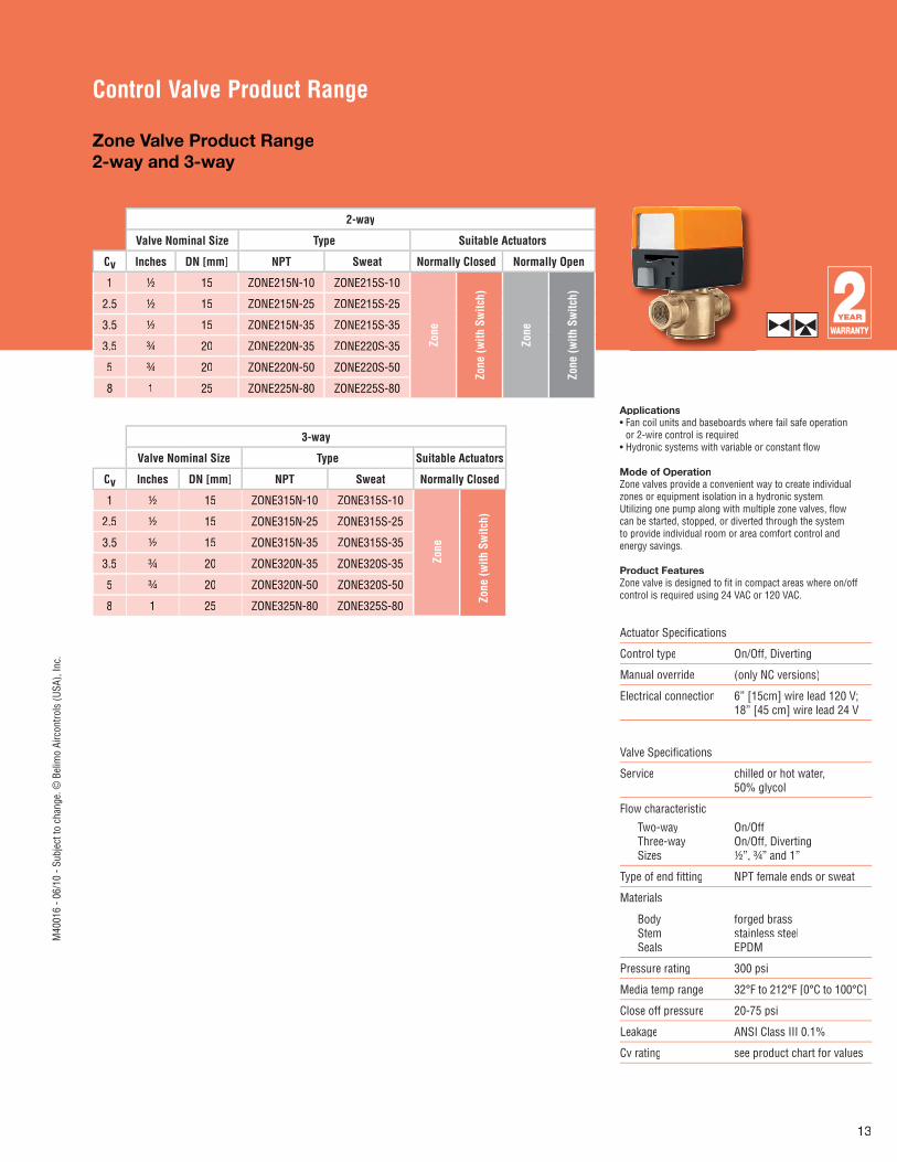
Zone Valve Product Range2-way and 3-way
Applications• Fan coil units and baseboards where fail safe operation
or 2-wire control is required• Hydronic systems with variable or constant fl ow
Mode of OperationZone valves provide a convenient way to create individualzones or equipment isolation in a hydronic system.Utilizing one pump along with multiple zone valves, fl owcan be started, stopped, or diverted through the systemto provide individual room or area comfort control andenergy savings.
Product FeaturesZone valve is designed to fi t in compact areas where on/offcontrol is required using 24 VAC or 120 VAC.
2-way2-way
Valve Nominal Size Type Suitable Actuators
Cv Inches DN [mm] NPT Sweat Normally Closed Normally Open
1 ½ 15 ZONE215N-10 ZONE215S-10
Zone
Zone
(with
Sw
itch)
Zone
Zone
(with
Sw
itch)
2.5 ½ 15 ZONE215N-25 ZONE215S-25
3.5 ½ 15 ZONE215N-35 ZONE215S-35
3.5 ¾ 20 ZONE220N-35 ZONE220S-35
5 ¾ 20 ZONE220N-50 ZONE220S-50
8 1 25 ZONE225N-80 ZONE225S-80
3-way
Valve Nominal Size Type Suitable Actuators
Cv Inches DN [mm] NPT Sweat Normally Closed
1 ½ 15 ZONE315N-10 ZONE315S-10
Zone
Zone
(with
Sw
itch)2.5 ½ 15 ZONE315N-25 ZONE315S-25
3.5 ½ 15 ZONE315N-35 ZONE315S-35
3.5 ¾ 20 ZONE320N-35 ZONE320S-35
5 ¾ 20 ZONE320N-50 ZONE320S-50
8 1 25 ZONE325N-80 ZONE325S-80
Actuator Specifi cations
Control type On/Off, Diverting
Manual override (only NC versions)
Electrical connection 6” [15cm] wire lead 120 V;18” [45 cm] wire lead 24 V
Valve Specifi cations
Service chilled or hot water, 50% glycol
Flow characteristic
Two-way Three-way Sizes
On/OffOn/Off, Diverting½”, ¾” and 1”
Type of end fi tting NPT female ends or sweat
Materials
Body Stem Seals
forged brassstainless steelEPDM
Pressure rating 300 psi
Media temp range 32°F to 212°F [0°C to 100°C]
Close off pressure 20-75 psi
Leakage ANSI Class III 0.1%
Cv rating see product chart for values
M40
016
- 06/
10 -
Subj
ect t
o ch
ange
. © B
elim
o Ai
rcon
trols
(USA
), In
c.
14
Control Valve Product Range
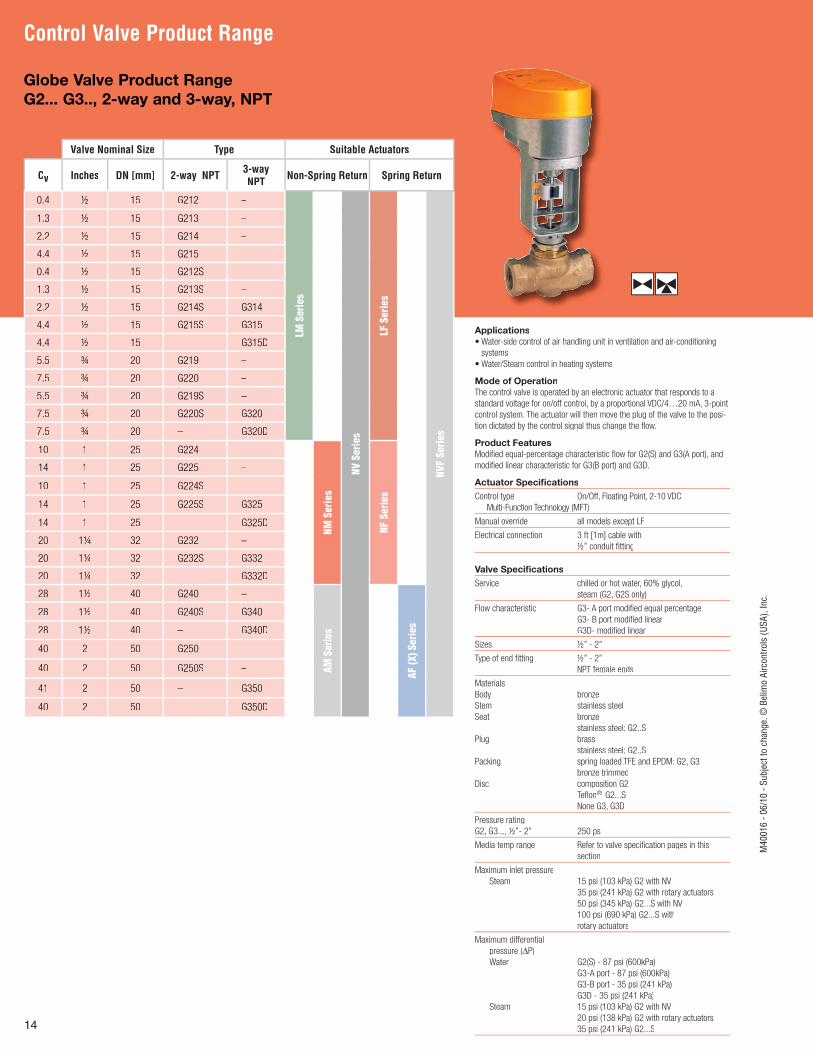
Globe Valve Product RangeG2... G3.., 2-way and 3-way, NPT
Valve Nominal Size Type Suitable Actuators
Cv Inches DN [mm] 2-way NPT 3-way NPT Non-Spring Return Spring Return
0.4 ½ 15 G212 –
LM S
erie
s
NV S
erie
s
LF S
erie
s
NVF
Serie
s
1.3 ½ 15 G213 –
2.2 ½ 15 G214 –
4.4 ½ 15 G215 –
0.4 ½ 15 G212S –
1.3 ½ 15 G213S –
2.2 ½ 15 G214S G314
4.4 ½ 15 G215S G315
4.4 ½ 15 – G315D
5.5 ¾ 20 G219 –
7.5 ¾ 20 G220 –
5.5 ¾ 20 G219S –
7.5 ¾ 20 G220S G320
7.5 ¾ 20 – G320D
10 1 25 G224 –
NM S
erie
s
NF S
erie
s
14 1 25 G225 –
10 1 25 G224S –
14 1 25 G225S G325
14 1 25 – G325D
20 1¼ 32 G232 –
20 1¼ 32 G232S G332
20 1¼ 32 – G332D
28 1½ 40 G240 –
AM S
erie
s
AF (X
) Ser
ies
28 1½ 40 G240S G340
28 1½ 40 – G340D
40 2 50 G250 –
40 2 50 G250S –
41 2 50 – G350
40 2 50 – G350D
Applications
• Water-side control of air handling unit in ventilation and air-conditioning
systems
• Water/Steam control in heating systems
Mode of Operation
The control valve is operated by an electronic actuator that responds to a
standard voltage for on/off control, by a proportional VDC/4…20 mA, 3-point
control system. The actuator will then move the plug of the valve to the posi-
tion dictated by the control signal thus change the fl ow.
Product Features
Modifi ed equal-percentage characteristic fl ow for G2(S) and G3(A port), and
modifi ed linear characteristic for G3(B port) and G3D.
Actuator Specifi cations
Control type On/Off, Floating Point, 2-10 VDC
Multi-Function Technology (MFT)
Manual override all models except LF
Electrical connection 3 ft [1m] cable with
½” conduit fi tting
Valve Specifi cations
Service chilled or hot water, 60% glycol,
steam (G2, G2S only)
Flow characteristic G3- A port modifi ed equal percentage
G3- B port modifi ed linear
G3D- modifi ed linear
Sizes ½” - 2”
Type of end fi tting ½” - 2”
NPT female ends
Materials
Body bronze
Stem stainless steel
Seat bronze
stainless steel: G2..S
Plug brass
stainless steel: G2..S
Packing spring loaded TFE and EPDM: G2, G3
bronze trimmed
Disc composition G2
Tefl on® G2...S
None G3, G3D
Pressure rating
G2, G3..., ½”- 2” 250 psi
Media temp range Refer to valve specifi cation pages in this
section
Maximum inlet pressure
Steam 15 psi (103 kPa) G2 with NV
35 psi (241 kPa) G2 with rotary actuators
50 psi (345 kPa) G2...S with NV
100 psi (690 kPa) G2...S with
rotary actuators
Maximum differential
pressure (Δ(( P)
Water G2(S) - 87 psi (600kPa)
G3-A port - 87 psi (600kPa)
G3-B port - 35 psi (241 kPa)
G3D - 35 psi (241 kPa)
Steam 15 psi (103 kPa) G2 with NV
20 psi (138 kPa) G2 with rotary actuators
35 psi (241 kPa) G2...S
M40
016
- 06/
10 -
Subj
ect t
o ch
ange
. © B
elim
o Ai
rcon
trols
(USA
), In
c.
15
Control Valve Product Range
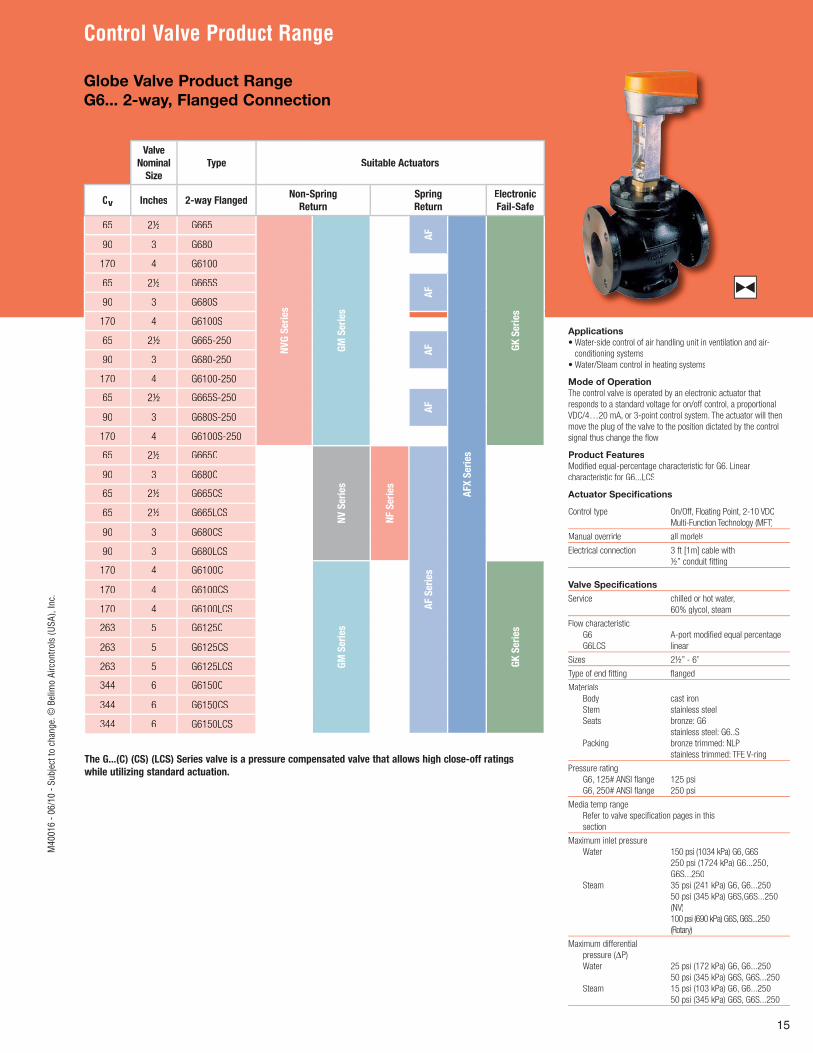
Globe Valve Product Range G6... 2-way, Flanged Connection
Valve
Nominal
Size
Type Suitable Actuators
Cv Inches 2-way FlangedNon-Spring
Return
Spring
Return
Electronic
Fail-Safe
65 2½ G665
NV
G S
eri
es
GM
Seri
es
AF
AFX
Seri
es
GK
Seri
es
90 3 G680
170 4 G6100
65 2½ G665S
AF
90 3 G680S
170 4 G6100S
65 2½ G665-250
AF
90 3 G680-250
170 4 G6100-250
65 2½ G665S-250
AF
90 3 G680S-250
170 4 G6100S-250
65 2½ G665C
NV
Seri
es
NF S
eri
es
AF S
eri
es
90 3 G680C
65 2½ G665CS
65 2½ G665LCS
90 3 G680CS
90 3 G680LCS
170 4 G6100C
GM
Seri
es
GK
Seri
es
170 4 G6100CS
170 4 G6100LCS
263 5 G6125C
263 5 G6125CS
263 5 G6125LCS
344 6 G6150C
344 6 G6150CS
344 6 G6150LCS
The G...(C) (CS) (LCS) Series valve is a pressure compensated valve that allows high close-off ratings
while utilizing standard actuation.
Applications
• Water-side control of air handling unit in ventilation and air-
conditioning systems
• Water/Steam control in heating systems
Mode of Operation
The control valve is operated by an electronic actuator that
responds to a standard voltage for on/off control, a proportional
VDC/4…20 mA, or 3-point control system. The actuator will then
move the plug of the valve to the position dictated by the control
signal thus change the fl ow.
Product Features
Modifi ed equal-percentage characteristic for G6. Linear
characteristic for G6...LCS
Actuator Specifi cations
Control type On/Off, Floating Point, 2-10 VDC
Multi-Function Technology (MFT)
Manual override all models
Electrical connection 3 ft [1m] cable with
½” conduit fi tting
Valve Specifi cations
Service chilled or hot water,
60% glycol, steam
Flow characteristic
G6 A-port modifi ed equal percentage
G6LCS linear
Sizes 2½” - 6”
Type of end fi tting fl anged
Materials
Body cast iron
Stem stainless steel
Seats bronze: G6
stainless steel: G6..S
Packing bronze trimmed: NLP
stainless trimmed: TFE V-ring
Pressure rating
G6, 125# ANSI fl ange 125 psi
G6, 250# ANSI fl ange 250 psi
Media temp range
Refer to valve specifi cation pages in this
section
Maximum inlet pressure
Water 150 psi (1034 kPa) G6, G6S
250 psi (1724 kPa) G6...250,
G6S...250
Steam 35 psi (241 kPa) G6, G6...250
50 psi (345 kPa) G6S,G6S...250
(NV)
100 psi (690 kPa) G6S, G6S...250
(Rotary)
Maximum differential
pressure (Δ(( P)
Water 25 psi (172 kPa) G6, G6...250
50 psi (345 kPa) G6S, G6S...250
Steam 15 psi (103 kPa) G6, G6...250
50 psi (345 kPa) G6S, G6S...250
M40
016
- 06/
10 -
Subj
ect t
o ch
ange
. © B
elim
o Ai
rcon
trols
(USA
), In
c.
16
Control Valve Product Range
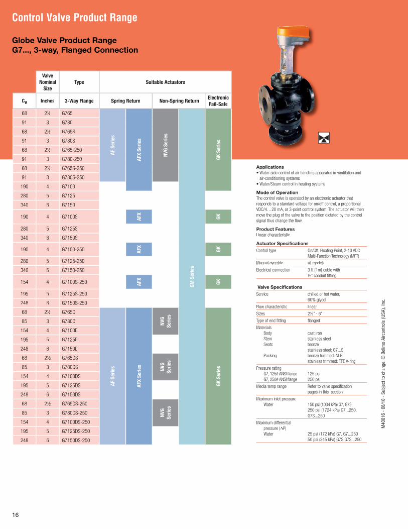
Globe Valve Product Range G7..., 3-way, Flanged Connection
Applications
• Water-side control of air handling apparatus in ventilation and
air-conditioning systems
• Water/Steam control in heating systems
Mode of Operation
The control valve is operated by an electronic actuator that
responds to a standard voltage for on/off control, a proportional
VDC/4…20 mA, or 3-point control system. The actuator will then
move the plug of the valve to the position dictated by the control
signal thus change the fl ow.
Product Features
Linear characteristic
Actuator Specifi cations
Control type On/Off, Floating Point, 2-10 VDC
Multi-Function Technology (MFT)
Manual override all models
Electrical connection 3 ft [1m] cable with
½” conduit fi tting
Valve Specifi cations
Service chilled or hot water,
60% glycol
Flow characteristic linear
Sizes 2½” - 6”
Type of end fi tting fl anged
Materials
Body cast iron
Stem stainless steel
Seats bronze
stainless steel: G7...S
Packing bronze trimmed: NLP
stainless trimmed: TFE V-ring
Pressure rating
G7, 125# ANSI fl ange 125 psi
G7, 250# ANSI fl ange 250 psi
Media temp range Refer to valve specifi cation
pages in this section
Maximum inlet pressure
Water 150 psi (1034 kPa) G7, G7S
250 psi (1724 kPa) G7...250,
G7S...250
Maximum differential
pressure (Δ(( P)
Water 25 psi (172 kPa) G7, G7...250
50 psi (345 kPa) G7S,G7S...250
Valve
Nominal
Size
Type Suitable Actuators
CCvv InchesInches 3-Way Flange3-Way Flange Spring ReturnSpring Return Non-Spring ReturnNon-Spring ReturnElectronic Electronic
Fail-SafeFail-Safe
68 2½ G765A
F S
eri
es
AFX
Seri
es
NV
G S
eri
es
GM
Seri
es
GK
Seri
es
91 3 G780
68 2½ G765S
91 3 G780S
68 2½ G765-250
91 3 G780-250
68 2½ G765S-250
91 3 G780S-250
190 4 G7100
280 5 G7125
340 6 G7150
190 4 G7100S AFX
GK
280 5 G7125S
340 6 G7150S
190 4 G7100-250 AFX
GK
280 5 G7125-250
340 6 G7150-250
154 4 G7100S-250 AFX
GK
195 5 G7125S-250
248 6 G7150S-250
68 2½ G765D
AF S
eri
es
AFX
Seri
es
NV
G
Seri
es
GK
Seri
es
85 3 G780D
154 4 G7100D
195 5 G7125D
248 6 G7150D
68 2½ G765DS
NV
G
Seri
es
85 3 G780DS
154 4 G7100DS
195 5 G7125DS
248 6 G7150DS
68 2½ G765DS-250
NV
G
Seri
es
85 3 G780DS-250
154 4 G7100DS-250
195 5 G7125DS-250
248 6 G7150DS-250
M40
016
- 06/
10 -
Subj
ect t
o ch
ange
. © B
elim
o Ai
rcon
trols
(USA
), In
c.
17
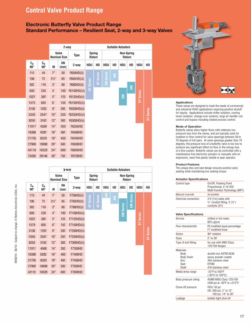
Electronic Butterfl y Valve Product RangeStandard Performance – Resilient Seat, 2-way and 3-way Valves
Actuator Specifi cationsControl type On/Off, Floating Point, Proportional, 2-10 VDC Multi-Function Technology (MFT)Manual override all modelsElectrical connection 3 ft [1m] cable with ½” conduit fi tting, 2 (½”) conduits (SY)
Valve Specifi cationsService chilled or hot water, 60% glycolFlow characteristic F6 modifi ed equal percentage F7 modifi ed linearAction 90° rotationSizes 2” to 30”Type of end fi tting for use with ANSI Class 125/150 fl angesMaterials Body ductile iron ASTM A536 Body fi nish epoxy powder coated Disc 304 stainless steel Seat EPDM Shaft 416 stainless steelMedia temp range -22°F to 250°F (-30°C to 120°C) Body pressure rating ASME/ANSI Class 125/150 (200 psi at -30°F to +275°F)Close-off pressure HDU: 50 psi HD: 200 psi, 2” to 12” 150 psi, 14” to 30”Leakage bubble tight shut-off
ApplicationsThese valves are designed to meet the needs of commercialand industrial HVAC applications requiring positive shutofffor liquids. Applications include chiller isolation, coolingtower isolation, change-over systems, large air handler coilcontrol and bypass including related process control.
Mode of OperationButterfl y valves allow higher fl ows with relatively lowpressure loss from the valves, and are typically used forisolation or fl ow control for valve openings between 30 to70 degrees of full open. At valve openings greater than 70degrees, the pressure loss of a butterfl y valve is too low toproduce any signifi cant effect on fl ow or the energy lossof a fl ow system. Butterfl y valves can be controlled with amaintenance-free electronic actuator or manually with anergonomic, wear-free plastic handle or gear operator.
Product FeaturesThe unique disc and seat design ensures positive valveseating while maintaining low seating torque.
2-way Suitable Actuators
ValveNominal Size Type Spring
ReturnNon-Spring
Return
Cv90°
Cv 60° IN
DN [mm] 2-way HDU HD HDU HD HDU HD HDU HD
115 44 2” 50 F650HD(U)
AF S
erie
s
AF S
erie
s
AM S
erie
s
AM
SY S
erie
s
SY S
erie
s
196 75 2½” 65 F665HD(U)
302 116 3” 80 F680HD(U)
GM600 230 4” 100 F6100HD(U)
GM1022 392 5” 125 F6125HD(U)
1579 605 6” 150 F6150HD(U)
3136 1202 8” 200 F6200HD(U)
5340 2047 10” 250 F6250HD(U)
8250 3162 12” 300 F6300HD(U)
11917 4568 14” 350 F6350HD
16388 6282 16” 400 F6400HD
21705 8320 18” 450 F6450HD
27908 10698 20” 500 F6500HD
43116 16528 24” 600 F6600HD
73426 28146 30” 750 F6750HD
Suitable Actuators
ValveNominal Size Type Spring
ReturnNon-Spring
Return
CCvv90°90°
CCvv60°60° ININ
DNDN[mm][mm] 3-way3-way HDUHDU HDHD HDUHDU HDHD HDUHDU HDHD HDUHDU HDHD
115 44 2” 50 F750HD(U)
AF S
erie
s
AF S
erie
s AM
AM
GM S
erie
s
SY S
erie
s
SY S
erie
s
196 75 2½” 65 F765HD(U)
GM S
erie
s
302 116 3” 80 F780HD(U)
600 230 4” 100 F7100HD(U)
1022 392 5” 125 F7125HD(U)
1579 605 6” 150 F7150HD(U)
3136 1202 8” 200 F7200HD(U)
5340 2047 10” 250 F7250HD(U)
8250 3162 12” 300 F7300HD(U)
11917 4568 14” 350 F7350HD
16388 6282 16” 400 F7400HD
21705 8320 18” 450 F7450HD
27908 10698 20” 500 F7500HD
43116 16528 24” 600 F7600HD
Control Valve Product RangeM
4001
6 - 0
6/10
- Su
bjec
t to
chan
ge. ©
Bel
imo
Airc
ontro
ls (U
SA),
Inc.
18
Control Valve Product Range
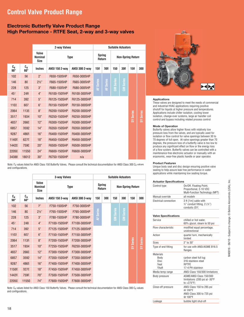
Electronic Butterfl y Valve Product RangeHigh Performance - RTFE Seat, 2-way and 3-way valves
2-way Valves Suitable Actuators
Valve Nominal
SizeType Spring
Return Non-Spring Return
Cv90°
Cv60° Inches ANSI 150 2-way ANSI 300 2-way 150 300 150 300 150 300
102 56 2” F650-150SHP F650-300SHP
AF S
erie
s
AF S
erie
s
GM S
erie
s
GM S
erie
s
SY S
erie
s
SY S
erie
s
146 80 2½” F665-150SHP F665-300SHP
228 125 3” F680-150SHP F680-300SHP
451 248 4” F6100-150SHP F6100-300SHP
714 392 5” F6125-150SHP F6125-300SHP
1103 607 6” F6150-150SHP F6150-300SHP
2064 1135 8” F6200-150SHP F6200-300SHP
3517 1934 10” F6250-150SHP F6250-300SHP
4837 2660 12” F6300-150SHP F6300-300SHP
6857 3592 14” F6350-150SHP F6350-300SHP
9287 4865 16” F6400-150SHP F6400-300SHP
11400 6270 18” F6450-150SHP F6450-300SHP
14420 7590 20” F6500-150SHP F6500-300SHP
22050 11550 24” F6600-150SHP F6600-300SHP
34388 18012 30” F6750-150SHP n/a
Note: Cv values listed for ANSI Class 150 Butterfl y Valves. Please consult the technical documentation for ANSI Class 300 Cv v valuesvand confi gurations.
3-way Valves Suitable Actuators
Valve Nominal
SizeType Spring
Return Non-Spring Return
Cv90°
Cv60° Inches ANSI 150 3-way ANSI 300 3-way 150 300 150 300 150 300
102 56 2” F750-150SHP F750-300SHP
AF S
erie
s
GM S
erie
s
GM S
erie
s
SY S
erie
s
SY S
erie
s
146 80 2½” F765-150SHP F765-300SHP
228 125 3” F780-150SHP F780-300SHP
451 248 4” F7100-150SHP F7100-300SHP
714 392 5” F7125-150SHP F7125-300SHP
1103 607 6” F7150-150SHP F7150-300SHP
2064 1135 8” F7200-150SHP F7200-300SHP
3517 1934 10” F7250-150SHP F6250-300SHP
4837 2660 12” F7300-150SHP F7300-300SHP
6857 3592 14” F7350-150SHP F7350-300SHP
9287 4865 16” F7400-150SHP F7400-300SHP
11500 3270 18” F7450-150SHP F7450-300SHP
14420 7590 20” F7500-150SHP F7500-300SHP
22050 11550 24” F7600-150SHP F7600-300SHP
Note: Cv values listed for ANSI Class 150 Butterfl y Valves. Please consult the technical documentation for ANSI Class 300 Cv v valuesvand confi gurations.
Actuator Specifi cationsControl type On/Off, Floating Point, Proportional, 2-10 VDC Multi-Function Technology (MFT)Manual override all modelsElectrical connection 3 ft [1m] cable with ½” conduit fi tting, 2 (½”) conduits (SY)
Valve Specifi cationsService chilled or hot water, 60% glycol, steam to 50 psiFlow characteristic modifi ed equal percentage, unidirectionalAction quarter turn, mechanically limitedSizes 2” to 30”Type of end fi tting for use with ANSI/ASME B16.5 fl angesMaterials Body carbon steel full lug Disc 316 stainless steel Seat RPTFE Shaft 17-4 PH stainlessMedia temp range ANSI Class 150/300 limitationsBody pressure ASME/ANSI Class 150/300 limitations (200 psi at -30°F to +275°F)Close-off pressure ANSI Class 150 to 285 psi @ 100°F ANSI Class 300 to 725 psi @ 100°F Leakage bubble tight shut-off
ApplicationsThese valves are designed to meet the needs of commercialand industrial HVAC applications requiring positiveshutoff for liquids at higher pressure and temperatures.Applications include chiller isolation, cooling towerisolation, change-over systems, large air handler coilcontrol and bypass including related process control.
Mode of OperationButterfl y valves allow higher fl ows with relatively lowpressure loss from the valves, and are typically used forisolation or fl ow control for valve openings between 30 to70 degrees of full open. At valve openings greater than 70degrees, the pressure loss of a butterfl y valve is too low toproduce any signifi cant effect on fl ow or the energy lossof a fl ow system. Butterfl y valves can be controlled with amaintenance-free electronic actuator or manually with anergonomic, wear-free plastic handle or gear operator.
Product FeaturesUnique body seat and disc design ensuring positive valvesealing to help assure leak free performance in waterapplications while maintaining low seating torque.
M40
016
- 06/
10 -
Subj
ect t
o ch
ange
. © B
elim
o Ai
rcon
trols
(USA
), In
c.
19
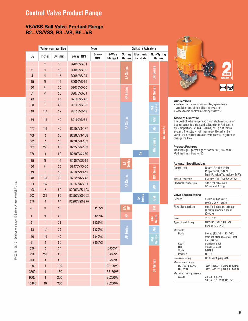
Control Valve Product Range
VS/VSS Ball Valve Product RangeB2...VS/VSS, B3...VS, B6...VS
Applications• Water-side control of air handling apparatus in
ventilation and air-conditioning systems• Water/Steam control in heating systems Mode of OperationThe control valve is operated by an electronic actuatorthat responds to a standard voltage for on/off control,by a proportional VDC/4…20 mA, or 3-point controlsystem. The actuator will then move the ball of thevalve to the position dictated by the control signal thuschange the fl ow.
Valve Nominal Size Type Suitable Actuators
Cv Inches DN [mm] 2-way NPT 3-way NPT
2-Way Flanged
Spring Return
Electronic Fail-Safe
Non-SpringReturn
1 ½ 15 B2050VS-01
LF S
erie
s
LM S
erie
s
SY S
erie
s
2 ½ 15 B2050VS-02
4 ½ 15 B2050VS-04
15 ½ 15 B2050VS-15
30 ¾ 20 B2075VS-30
NF S
erie
s
NM S
erie
s
51 ¾ 20 B2075VS-51
43 1 25 B2100VS-43
68 1 25 B2100VS-68
AF S
erie
s
AM
Serie
s
48 1¼ 32 B2125VS-48
84 1½ 40 B2150VS-84 GM
177 1½ 40 B2150VS-177 AM
108 2 50 B2200VS-108
GM S
erie
s
389 2 50 B2200VS-389
503 2½ 65 B2250VS-503
370 3 80 B2300VS-370 GK
15 ½ 15 B2050VSS-15
LF
Serie
s
30 ¾ 20 B2075VSS-30
NM S
erie
s
43 1 25 B2100VSS-43
AF S
erie
s
48 1¼ 32 B2125VSS-48
84 1½ 40 B2150VSS-84
AM
108 2 50 B2200VSS-108
503 2½ 65 B2250VSS-503
GKSe
ries
GM370 3 80 B2300VSS-370
4.8 ½ 15 B315VS LF/
NF LM
11 ¾ 20 B320VS NF
NM
Serie
s
21 1 25 B325VS
AF S
erie
s
33 1¼ 32 B332VS AM
49 1½ 40 B340VS
GM
Serie
s
91 2 50 B350VS
330 2 50 B650VS
SY S
erie
s
420 2½ 65 B665VS
600 3 80 B680VS
1200 4 100 B6100VS
3300 6 150 B6150VS
9000 8 200 B6200VS
12400 10 250 B6250VS
Product FeaturesModifi ed equal percentage of fl ow for B2, B3 and B6.Modifi ed linear fl ow for B3.
Actuator Specifi cationsControl type On/Off, Floating Point, Proportional, 2-10 VDC Multi-Function Technology (MFT)Manual override LM, NM, GM, AM, SY, AF, GKElectrical connection 3 ft [1m] cable with ½” conduit fi tting
Valve Specifi cationsService chilled or hot water, (60% glycol), steamFlow characteristic modifi ed equal percentage (2-way), modifi ed linear (3-way)
Sizes ½” to 10”Type of end fi tting NPT (B2...VS & B3.. VS) fl anged (B6...VS) Materials Body bronze (B2...VS & B3...VS), stainless steel (B2...VSS), cast iron (B6...VS) Stem stainless steel Ball stainless steel Seats MPTFE Packing RPTFEPressure rating Up to 2000 psig WOGMedia temp range B2...VS, B3...VS -22°F to 280°F [-30°C to 138°C] B2...VSS -22°F to 298°F [-30°C to 148°C]Maximum inlet pressure Steam 35 psi B2...VS 50 psi B2...VSS, B6...VS
M40
016
- 06/
10 -
Subj
ect t
o ch
ange
. © B
elim
o Ai
rcon
trols
(USA
), In
c.
20
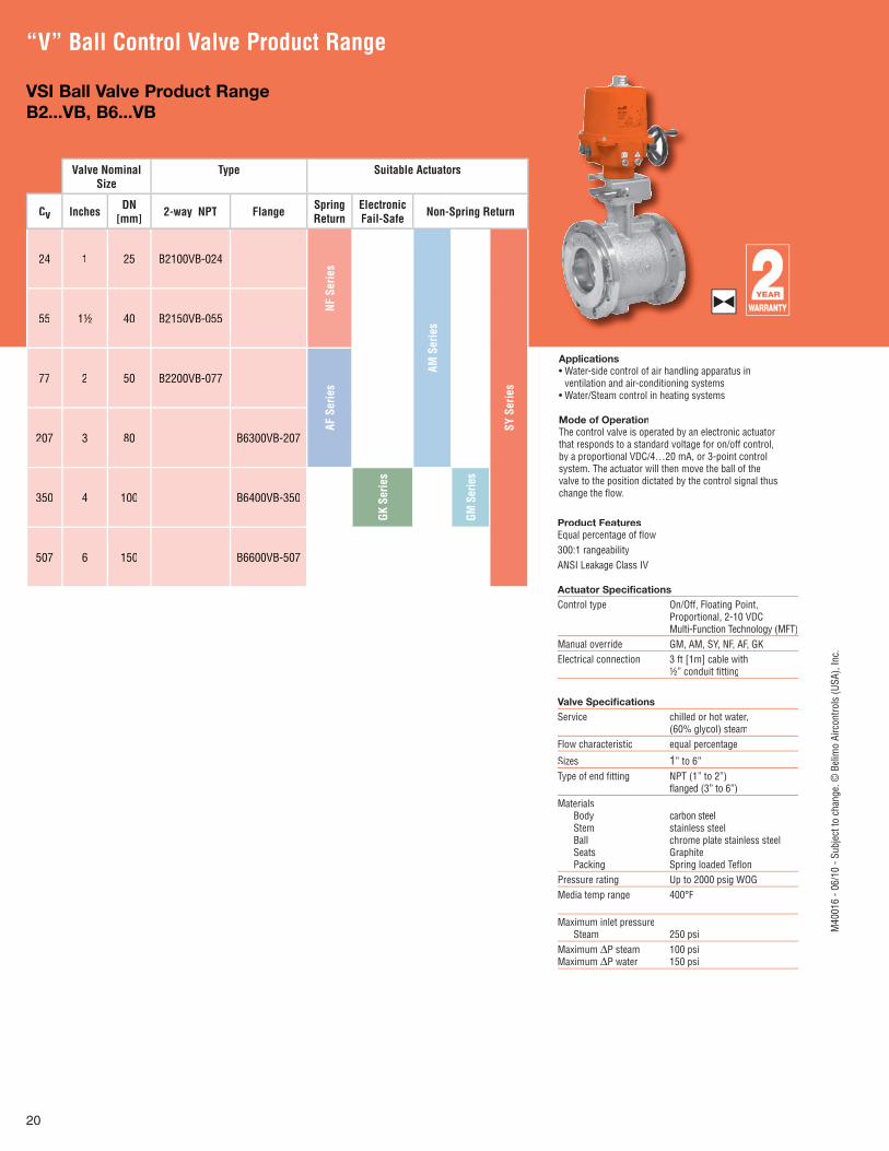
“V” Ball Control Valve Product Range
VSI Ball Valve Product RangeB2...VB, B6...VB
Applications• Water-side control of air handling apparatus in
ventilation and air-conditioning systems• Water/Steam control in heating systems Mode of OperationThe control valve is operated by an electronic actuatorthat responds to a standard voltage for on/off control,by a proportional VDC/4…20 mA, or 3-point controlsystem. The actuator will then move the ball of thevalve to the position dictated by the control signal thuschange the fl ow.
Valve NominalSize
Type Suitable Actuators
Cv Inches DN [mm] 2-way NPT Flange Spring
ReturnElectronic Fail-Safe Non-Spring Return
24 1 25 B2100VB-024
NF S
erie
s
AM S
erie
s
SY S
erie
s
55 1½ 40 B2150VB-055
77 2 50 B2200VB-077
AF S
erie
s
207 3 80 B6300VB-207
350 4 100 B6400VB-350
GK S
erie
s
GM S
erie
s
507 6 150 B6600VB-507
Product FeaturesEqual percentage of fl ow300:1 rangeabilityANSI Leakage Class IV
Actuator Specifi cationsControl type On/Off, Floating Point, Proportional, 2-10 VDC Multi-Function Technology (MFT)Manual override GM, AM, SY, NF, AF, GKElectrical connection 3 ft [1m] cable with ½” conduit fi tting
Valve Specifi cationsService chilled or hot water, (60% glycol) steamFlow characteristic equal percentage
Sizes 1” to 6”Type of end fi tting NPT (1” to 2”) fl anged (3” to 6”)Materials Body carbon steel Stem stainless steel Ball chrome plate stainless steel Seats Graphite Packing Spring loaded Tefl onPressure rating Up to 2000 psig WOGMedia temp range 400°F
Maximum inlet pressure Steam 250 psiMaximum ΔP steam 100 psiMaximum ΔP water 150 psi
M40
016
- 06/
10 -
Subj
ect t
o ch
ange
. © B
elim
o Ai
rcon
trols
(USA
), In
c.
21
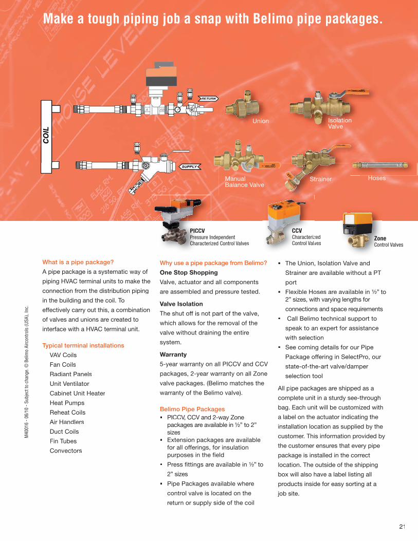
PICCVndependent Pressure Ized Control ValvesCharacteri
CCVzedCharacterizvesControl Valv
ne Zontrol ValvesCon
Make a tough piping job a snap with Belimo pipe packages.
What is a pipe package?
A pipe package is a systematic way of
piping HVAC terminal units to make the
connection from the distribution piping
in the building and the coil. To
effectively carry out this, a combination
of valves and unions are created to
interface with a HVAC terminal unit.
Typical terminal installations
VAV Coils
Fan Coils
Radiant Panels
Unit Ventilator
Cabinet Unit Heater
Heat Pumps
Reheat Coils
Air Handlers
Duct Coils
Fin Tubes
Convectors
Why use a pipe package from Belimo?
One Stop Shopping
Valve, actuator and all components
are assembled and pressure tested.
Valve Isolation
The shut off is not part of the valve,
which allows for the removal of the
valve without draining the entire
system.
Warranty
5-year warranty on all PICCV and CCV
packages, 2-year warranty on all Zone
valve packages. (Belimo matches the
warranty of the Belimo valve).
Belimo Pipe Packages PICCV, CCV and 2-way Zone packages are available in ½” to 2” sizes Extension packages are available for all offerings, for insulation purposes in the fi eld
Press fi ttings are available in ½” to
2” sizes
Pipe Packages available where
control valve is located on the
return or supply side of the coil
The Union, Isolation Valve and
Strainer are available without a PT
port
Flexible Hoses are available in ½” to 2” sizes, with varying lengths for
connections and space requirements
Call Belimo technical support to
speak to an expert for assistance
with selection
See coming details for our Pipe
Package offering in SelectPro, our
state-of-the-art valve/damper
selection tool
All pipe packages are shipped as a
complete unit in a sturdy see-through
bag. Each unit will be customized with
a label on the actuator indicating the
installation location as supplied by the
customer. This information provided by
the customer ensures that every pipe
package is installed in the correct
location. The outside of the shipping
box will also have a label listing all
products inside for easy sorting at a
job site.
Strainer
Union Isolation Valve
Manual Balance Valve
Hoses
UUUnUnion
M40
016
- 06/
10 -
Subj
ect t
o ch
ange
. © B
elim
o Ai
rcon
trols
(USA
), In
c.

22
Retrofi t Solutions for valve and damper actuators which increase the quality and reliability of your entire system.
Discover Belimo‘s Retrofi t Resource Team
dedicated to offering you options, support and
guidance.
Belimo has a dedicated team of retrofi t professionals to provide you the
guidance and resource for getting the most from your HVAC system. If you
are experiencing broken or outdated actuators, valves that are not perfor-
ming or are causing unnecessary energy consumption; Belimo dedicated
retrofi t team can help you.
Belimo has a complete in-house machine shop with the ability to fabricate
custom linkages for valve automation. Product mediums include stainless
steel, cold rolled steel or brass. With our machining capabilities and our re-
trofi t team we can design and create custom retrofi t linkage solutions for your
existing valves, regardless of the manufacturer.
Belimo actuators and valves lead the industry in cutting-edge technology
and value. Whether electronic or pneumatic, there is a simple way to retrofi t.
Replacement solutions are available
for Siemens®, Johnson Controls®,
Honeywell®, Invensys®, Robertshaw®,
Siebe, Barber Colman®, Landis®,
Powers®, Warren®, Apollo®, Bray®,
Centerline®, Challenger®, Chemtrol®,
Dezurik®, Flowseal®, FNW®, Gruvlok®,
Hammond®, Keystone®, K-LOK®,
Metrafl ex®, Milwaukee®, Mueller®,
Nibco®, PDC®, Quartermaster®,
Victaulic®, Watts® and many more.
Belimo Retrofi t Installations:
Valve Retrofi tYale Kroon HallNew Haven, CT
Valve Retrofi tAetnaDenver, CO
Valve Retrofi tAssisi HeightsSisters of St. FrancisRochester, MN
Actuator Retrofi tNew York TimesNew York City, NY
Actuator Retrofi tUniversity ofConnecticut (UCONN),Storrs, CT
Hennepin County Courthouse, Minneapolis, MNCrown Plaza, Williamsburg, VABank of America, San Francisco,CAFairchild Air Force Base, Seattle, WASeattle University, Seattle, WASt. Anthony’s Medical Center, St Louis, MO
am
ort and New UGSL1200 Linkage
for Siemens® 599
M40
016
- 06/
10 -
Subj
ect t
o ch
ange
. © B
elim
o Ai
rcon
trols
(USA
), In
c.
1
2
3
Ordering Example
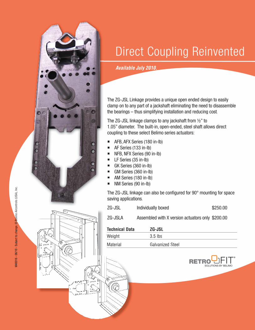
The ZG-JSL Linkage provides a unique open ended design to easily clamp on to any part of a jackshaft eliminating the need to disassemblethe bearings – thus simplifying installation and reducing cost.
The ZG-JSL linkage clamps to any jackshaft from ½” to1.05” diameter. The built-in, open-ended, steel shaft allows direct coupling to these select Belimo series actuators:
AFB, AFX Series (180 in-lb) AF Series (133 in-lb) NFB, NFX Series (90 in-lb) LF Series (35 in-lb) GK Series (360 in-lb) GM Series (360 in-lb) AM Series (180 in-lb) NM Series (90 in-lb)
The ZG-JSL linkage can also be confi gured for 90° mounting for spacesaving applications.
ZG-JSL Individually boxed $250.00
ZG-JSLA Assembled with X version actuators only $200.00
Technical Data ZG-JSLWeight 3.5 lbs
Material Galvanized Steel
rface for easy ordering
Direct Coupling ReinventedAvailable July 2010.
M40
016
- 06/
10 -
Subj
ect t
o ch
ange
. © B
elim
© B
elim
o Ai
rcon
trols
(USA
), In
c.
Belimo Platinum Distributors
US
A ACR Supply Company Inc.2719 Hillsborough RoadDurham, NC 27705Phone: 919-286-2228With branches in NC
Aireco Supply9120 Washington BoulevardSavage, MD 20763-0414Phone: 301-953-8800With branches in MD, VA
Amcon Controls, Inc.11906 Warfield StreetSan Antonio,TX 78216Phone: 210-349-6161Houston, TX branch 713-464-7002
Applied AutomationA Wilson Mohr Company3186 South Washington Street, #230Salt Lake City, UT 84115Phone: 801-486-6454
Boston Aircontrols, Inc.8 Blanchard RoadBurlington, MA 01803Phone: 781-272-5800
Charles D. Jones Co.445 Bryant Street, Unit #1Denver, CO 80204-4800Phone: 800-777-0910With branches in CO, MO, KS
Climatic Control Div/ICD5061 W. State StreetMilwaukee, WI 53208Phone: 800-242-1656With branches in WI
Cochrane Supply and Engineering, Inc.30303 Stephenson HighwayMadison Heights, MI 48071-1633Phone: 800-482-4894With branches in MI and Maumee, OH
Columbus Temperature Control1053 E. 5th AvenueColumbus, OH 43201Phone: 800-837-1837
Controlco5600 Imhoff Drive, Suite GConcord, CA 94520Phone: 925-602-7728With branches in CA, NV
Control Products9101 Jameel, Suite 130Houston, TX 77447Phone: 713-690-6300
Edward C. Smyers & Co.223 Fort Pitt BoulevardPittsburgh, PA 15222-1505Phone: 412-471-3222
Engineered Control Systems4805 N.W. 79th AvenueSuite 11Miami, FL 33166Phone: 305-418-8901With branches in FL
G & O Thermal Supply5435 N. Northwest HighwayChicago, IL 60630Phone: 773-763-1300With branches in IL
Industrial Controls Distributors LLC1776 Bloomsbury AvenueWanamassa, NJ 07712Phone: 800-631-2112With branches inGA, KY, IN, MA, ME, NC, NY, OH, PA, TN
Interstate HVAC Controls30 Vineland StreetBrighton, MA 02135 Phone: 617-782-9000
Jackson Controls1708 E. 10th StreetIndianapolis, IN 46201Phone: 317-231-2200
M & M Controls9E West Aylesbury RoadTimonium, MD 21093Phone: 410-252-1221With a branch in Alexandria, VA
MICONTROLS, Inc.6516 5th Place SouthSeattle, WA 98124Phone: 800-877-8026With branches in WA, OR
Meier Supply123 Brown StreetJohnson City, NY 13790 Phone: 607-797-7700With branches in NY, PA
Minvalco, Inc.3340 Gorham AvenueMinneapolis, MN 55426-4267Phone: 952-920-0131With branches in MN
RSD/Refrigeration Supply Distribution26021 Atlantic Ocean DriveLake Forest, CA 92630Phone: 949-380-7878With branches inCA, NV, OR, AK, AZ, ID, UT, WA, MT
Saint Louis Boiler Supply, Co. 617 Hanley Industrial CourtSt. Louis, MO 63144Phone: 314-962-9242
South Side Control Supply, Co. 488 N. Milwaukee AvenueChicago, IL 60610-3923Phone: 312-226-4900With branches in IL, IN
Stromquist and Company4620 Atlanta RoadSmyrna, GA 30080Phone: 404-794-3440With a branch in Orlando, FL
Temperature Control Systems10315 Brockwood RoadDallas, TX 75238Phone: 214-343-1444With branches in OK, TX
Tower Equipment Co., Inc.1320 West Broad StreetStratford, CT 06615Phone: 800-346-4647
Twinco Supply Corporation55 Craven StreetHuntington Station, NY 11746-2143Phone: 800-794-3188With branches in NY
Wilson-Mohr, Inc.12610 West Airport Blvd, Suite 100Sugarland, TX 77478Phone: 281-295-8850
For a complete list of distributorsin Canada, please visit ourwebsite: www.belimo.caor call toll free: 866-805-7089C
AN
AD
A
Belimo worldwide: www.belimo.com
BELIMO AmericasUSA Locations, 43 Old Ridgebury Road, Danbury, CT 06810Tel. 800-543-9038, Fax 800-228-8283, [email protected]
1049 Fortunato Loop, Sparks, NV 89436Tel. 800-987-9042, Fax 800-987-8875, [email protected]
Canada Locations, 14/16 – 5716 Coopers Avenue, Mississauga, Ontario L4Z 2E8Tel. 866-805-7089, Fax 905-712-3124, [email protected]
merica & The Caribbean Customer Service,Latin Amm Tel. 203-791-8396, Fax 203-791-9139, [email protected]
M40
016
- 06/
10 -
Subj
ect t
o ch
ange
. © B
elim
o Ai
rcon
trols
(USA
), In
c.0
- S