CATALOGED BY WUb[, - DTIC · cataloged by wub[, . t1. /9,j do not destroy s.. .. return to wadc...
42
CATALOGED BY WUb[, . T1. /9,j DO NOT DESTROY S.. .. RETURN To WADC TECHNICAL REPORT 541-83 7'C,'-fNrCAL DOCUMENT WADC TECHNA R R -3 CONTROL SECTION ADtq0 g WCOSI.3 FILE COPY, /} 9 PRELIMINARY MICROSCOPIC STUDIES OF CERMETS AT HIGH TEMPERATURES EARLE T. MONTGOMERY THOMAS S. SHEVLIN HAROLD M. GREENHOUSE HERBERT W. NEWKIRK THE OHIO STATE UNIVERSITY RESEARCH FOUNDATION APRIL 1955 Statement A Approved for Public Release W WRIGHT AIR DEVELOPMENT CENTER
Transcript of CATALOGED BY WUb[, - DTIC · cataloged by wub[, . t1. /9,j do not destroy s.. .. return to wadc...

CATALOGED BY WUb[, .T1. /9,j DO NOT DESTROY
S.. .. RETURN ToWADC TECHNICAL REPORT 541-83 7'C,'-fNrCAL DOCUMENT
WADC TECHNA R R -3 CONTROL SECTION
ADtq0 g WCOSI.3
FILE COPY,
/} 9
PRELIMINARY MICROSCOPIC STUDIES
OF CERMETS AT HIGH TEMPERATURES
EARLE T. MONTGOMERY
THOMAS S. SHEVLIN
HAROLD M. GREENHOUSE
HERBERT W. NEWKIRK
THE OHIO STATE UNIVERSITY RESEARCH FOUNDATION
APRIL 1955
Statement AApproved for Public Release
W
WRIGHT AIR DEVELOPMENT CENTER

NOTICE
When Government drawings, specifications, or other data areusedfor any purpose other than in connection with a definitely related Govern-ment procurement operation, the United States Government thereby In-curs no responsibility nor any obligation whatsoever; and the fact thatthe Government may have formulated, furnished, or in any way suppliedthe said drawings, specifications, or other data, is not to be regardedby implication or otherwise as in any manner licensing the holder orany other person or corporation, or conveying any rights or permissionto manufacture, use, or sell anypatented invention that may in any waybe related thereto.

WADC TECHNICAL REPORT 54-33
PRELIMINARY MICROSCOPIC STUDIES
OF CERMETS AT HIGH TEMPERATURES
EARLE T. MONTGOMERY
THOMAS S. SHEVLIN
HAROLD M. GREENHOUSE
HERBERT W. NEWKIRK
THE OHIO STATE UNIVERSITY RESEARCH FOUNDATION
APRIL 1955
MATERIALS LABORATORY
CONTRACT No. AF 33(038)-16911
PROJECT No. 7350
WRIGHT AIR DEVELOPMENT CENTER
AIR RESEARCH AND DEVELOPMENT COMMAND
UNITED STATES AIR FORCE
WRIGHT-PATTERSON AIR FORCE BASE, OHIO
Carpenter Litho & Prtg. Co., Springfield, 0.200 - 14 October 1955

FOFRORD
This report was prepared by the Ohio State UniversityResearch Foundation unler USAF Contract No. 33(038)-16911.This work was accomplished during the period of September1952 to September 1953. The contract was initiated underProject No. 7350, "Ceramic and Cermet Materials", Task No*73500 "Ceramic and Cermet Materials Development, formerlyRDO No. 605-233. "Ceramic and Cermet Materials Development",and was administered under the direction of the MaterialsLaboratory, Directorate of Research, Wright Air DevelopmentCenter, with Lt. Robert S. Thompsen acting as the projectengineer.
Personnel participating in the research and prepara-tion of the report include T. S. Sheilin, H. M. Greenhouse,H. Wo Newkirk, L. T. Trostel, Sr., G. A. Bole and E. ToMontgomery.
VIADC TR 54-33

ABSTRACT
This report covers the determination of some of the physical
properties of cermet IIIB not previously repcrted. It also covers
the design, construction, and testing of special equipment required
for the study of the microstructure of TiC base cermets.
The initial study of possible phase changes and changes in
microstructure of some TiC base cermets, with time, at high tempera-
tures is reported. A tentative theory is advanced in explanation
of the steep slope of the stress-rupture curves for TiC+Ni cermets
of the type produced by Kennametal, Inc.
In preparation for this study the following special equipment
was built: a high-temperature x-ray camera, a vacuum quench fur-
nace, and apparatus for the determination of coefficients of
thermal conductivity at temperatures to 17000 F. This equipment
is described in detail.
A preliminary evaluation of the potenti4jlties of "iB 2 and
MoSi 2 as components of a cermet is discussed.
PJBLICATI ON HEVIE
This report has been reviewed and is approved.
FOR THE COIANDER:
M. R. WHITMORETechnical DirectorMaterials LaboratoryDirectorate of Research
WADC TR 54-33 tit
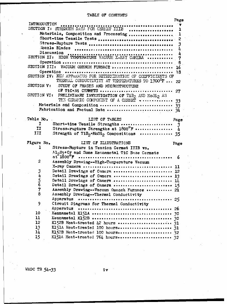
TABLE OF CONTENTSPageINTRODUCTION .,....,..... ..... ,.0.00... 'v
SECTION I: STRENGTH DATI FOR CM1:ET IIIB 1............... 1Materials, Composition and Processing ..... ,*.*.........*.a 1Short-time Tensile Tests ......... .................. e... 2Stress-Rupture Tests ....... *0000.. . *.0..*606..e.44...00* 3
Discussion oze Bade 0,0 ..... .................. ......... ** 4SECTION II: HIGH TEMPERATURE VACUUM X-RAY CAERA 7.,....".. 7
Operation ... . .. . . . . .. . . . . . . ... . . ,... 8SECTION III, VACUUMQ UENCH FURNACE. ........... 16
Operation a...... .............. .................... *** *. isSECTION IV: NE1I APPR4ATUS FOR DET' NATI01 OF COEFFICIENTS OF
TIRMA1L CODUCTIVITY AT T2-1FERATURES TO 1700OF ... 22SECTION V: STUDY OF PHASES AND MICROSTRUCTURE
OF TIC+Ni CERMFTS ............... **...............* 27SECTION VI: PRELIMINARY INVESTIGATION OF TiE2 A4,D MoSi 2 AS
THE CERAU IC C%1POHEM-NT OF A CEM11?T ............. o 33Materials and Composition .............. 33Fabrication and Factual Data ........................... 34
Table No. LIST OF TABLES PageI Short-time Tensile Strengths ..................... 3
II Stress-rupture Strengths at 1800OF e ............... 4III Strength of TiB2 +MoSi 2 Compositions ............. 35
Figure No. LIST OF ILLUSTRATIONS Page1 Stress-Rupture in Tension Cermet IIIB vs.
Al 2 03 +Cr and Some Kennametal TiC BRse CermetsatO1800OF *......... ........... .............. .. 6
2 Assembly Drawing--High-Temperature VacuumX-ray Camera e ..... **........*. .......... 11
3 Detail Drawings of Camera •m....................... 124 Detail Drawings of Camera ............... 135 Detail Drawings of Camera i....... so...........146 Detail Drawings of Camera ....... 157 Assembly Drawing--Vacuum Quench Furnace ....... 218 Assembly Drawing--Thermal Conductivity
Apparatus ... 0 ,*.... .............. g. ..... . 259 Circuit Diagrams for Thermal Conductivity
Apparatus ,.......... ............... 2610 Kennametal K151A 3011 Kennametal K152B •••....................... •, • •. • 3012 KI52B Heat-treated 42 hours 3113 K151A Heat-treated 100 hours................ ..... 3114 K152B Heat-treated 100 hours. .................... 3215 K151A Heat-treated 764 hours.. .................... 32
VIADC TR 54-33 iv

INTRODUCTION
This is a summary report and consists essentially of thematerial contained in six bimonthly reports submitted under thecontract to the Materials Laboratory, Directorate of Research,Wright Air Development Center, Wright-Patterson Air Force Base,Ohio. The research and development program covered by thereport is a continuation of the work reported in WADC TechnicalReport No. 53-287. The principal studies were two in number.
1. The evaluation of the physical properties of the prom-ising cermet III B having the composition 55.4 TiC + 17.9 TiB2 +10.0 Si + 16.7 Co was continued. The stress-to-rupture curvefor 1800°F was determined and solid nozzle-diaphragm partitionblades of airfoil contour were fabricated and tested by thePower Plant Laboratory, Directorate of Laboratories, WADC.
2. One of the best cermet compositions developed to dateis composed of titanium carbide bonded with 20 to 30 per cent ofnickel, a nickel-molybdenum alloy, or a nickel-chromium alloy.A cermet of this type produced by Kennametal, Inc., Latrobe,Pennsylvania, has been extensively tested in the form of bothnozzle blades and rotor blades. This type of cermet meets mostof the requirements for a blading material except that it isquite brittle and its stress-to-rupture curve shows as steepa slope as the curves for the better blade alloys. It wasconsidered highly desirable to determine the cause of thisrapid loss of strength, with time, at temperatures between16000 and 1800 0 F.
Extensive preparations were made for this study, and pre-liminary data together with a tentative explanation of thecause of strength deterioration are included in this report.In preparation for this study, a high-temperature x-ray camerawas built and a special vacuum quench furnace was designed andconstructed. As supplementary equipment for the evaluation ofthis and other cermets, an elaborate apparatus has beendesigned and built with which to determine coefficients ofthermal conductivity at temperatures to 17000 F.
A third study has been initiated during this period andcarried on as time has permitted. It involves a study of thepossibilities of using MOSi 2 and TiB2, singly or in combination, asthe ceramic component of a high-temperature cermet. This studyis closely tied to efforts to improve the heat-shock resistanceof cermet III B, which proved to be unsatisfactory in thisrespect presumably because the cobalt binder metal is converted,in sintering, to brittle cobalt monosilicide leaving no ductilemetal phase in the cermet.
WADC TR 54-33 v

SECTION I
STRENGTH DATA FOR CERMET III B
The development of cermet body III B has been coveredin a previous report. Further data on the strength of thiscermet and its resistance to thermal cycling are given here.
1. MATERIALS
The following materials were used in making the testspecimens:
TiC: Minus 325 mesh containing 80.4% Ti; 19.5% total C;0.10% free C; 0.08% total Fe; Norton Company.
TiB2 : Minus 20 mesh containing 66.51% Ti, 31.1% B and 1.7%C + 0.69% minor impurities. (1.2% estimated free C);Norton Company.
Si: Minus 325 mesh, 97% Si; Charles Hardy, Inc.
Co: Minus 300 mesh, 97.5% Co; Charles Hardy, Inc.
2. COMPOSITION
The composition in weight per cent is 55.4% TiC, 17.9%TiB2 , 10.0% Si, 16.7% Co.
3. PROCESSING
(a) Milling
Batches containing 500 grams of the above compositionwere milled 50 hours in a one-quart steel mill, using benzeneas the vehicle and cobalt-bonded tungsten carbide slugs asthe grinding medium.
(b) Forming
Following air drying and drying overnight at 1000C theabove batch was pressed hydrostatically at 35,000 psi in theform of a blank. This blank was crushed in a mortar andscreened through a 65-mesh screen. The prepressed granulatedbatch was then packed in thin-walled rubber tubes retained in
WADe Th 54-33 1

appropriate lengths of perforated brass pipe. The air wasevacuated from the powder and the ends of the rubber tubingclosed. As a result of subjecting this assembly to a hydro-static pressure of 35,000 psi, cylindrical rod blanks approxi-mately 0.6 inch in diameter by 12 inches long were obtained.
( c) Fi•ring'
The rod blanks were fired in a furnace consisting of agas-tight refractory porcelain tube heated within a tubularGlobar element surrounded with suitable insulating refractories.They were heated at a rate of approximately 400OF per hour to asoaking temperature of 2760-27900F, and held at this temperaturefor 1.5 hours.
(d) Grinding
The fired rod blanks approximately 0.5 inch in diameterbyl0 inches long were ground on a modified lathe speciallydesigned for this purpose to form tensile test, specimens approx-imately 9 inches long by 0.375 inch in diameter containing anecked center section ground on a 4.69-inch radius. This producesa necked length 1.5 inches long containing a minimum centersection 0.250 inch in diameter.
SHORT-TIME TENSILE TESTS
The tensile test specimens were sandblasted on the ends andwrapped with two turns of 1-inch wide asbestos tape cementedwith sodium silicate to provide for gripping and accomodation inthe jaw assemblies. The tensile test machine employs coldgrips and incorporates pneumatic loading, jaw aligning, andfurnace heating features of proven value in the tensile testingof brittle materials. The load is applied smoothly by cylinder-gas pressure acting on a hydraulic piston and cylinder. Alignmentbetween the heads which contain the Jaws is preserved duringmounting and throughout the loading cycle by guide rods press-fitted into one head, and sliding in the other head. A small,platinum-wound furnace fits around the specimen and betweenthe heads, which are cooled with dry ice for these tests. Speci-mens were tested at 750F, 1800OF, 20000F, and 2200oF and theresults are shown in Table I.
WADC TR 54-33 2

TABLE I. SHORT-TIME TENSILE STRENGTHS
Temperature OF Breaking Stress, psi
75 0 F 26,70028,100
1800OF 26,82228,914
2000OF 39,36333,567
2200OF 20,10913,380
STRESS-RUPTURE TESTS
1. SPECIMENS
Standard rod specimens identical with those describedfor short-time tensile tests were prepared for stress-to-rupture testing.
2. TESTING
The equipment used is similar to that described for short-time tensile testing and in addition provides for maintenanceof a constant mechanically applied load and a constant sustainedtemperature, with the necessary auxiliary equipment for tempera-ture check purposes and timing the duration bf the test run.
This equipment has been previously described in detail. 1
The rods initially tested failed at relatively low loadingsand at the relatively cool locations between the furnace and thewater-cooled grips where the temperature is between 800 and 9000F..This type of failure is attributed to low-temperature oxidation.Since this composition develops oxidation resistance upon heatingto a relatively high temperature, through the production of aborosilicate glass skin, the practice of subjecting all rods toa preoxidizing treatment for 24 hours at 2000OF was adopted.
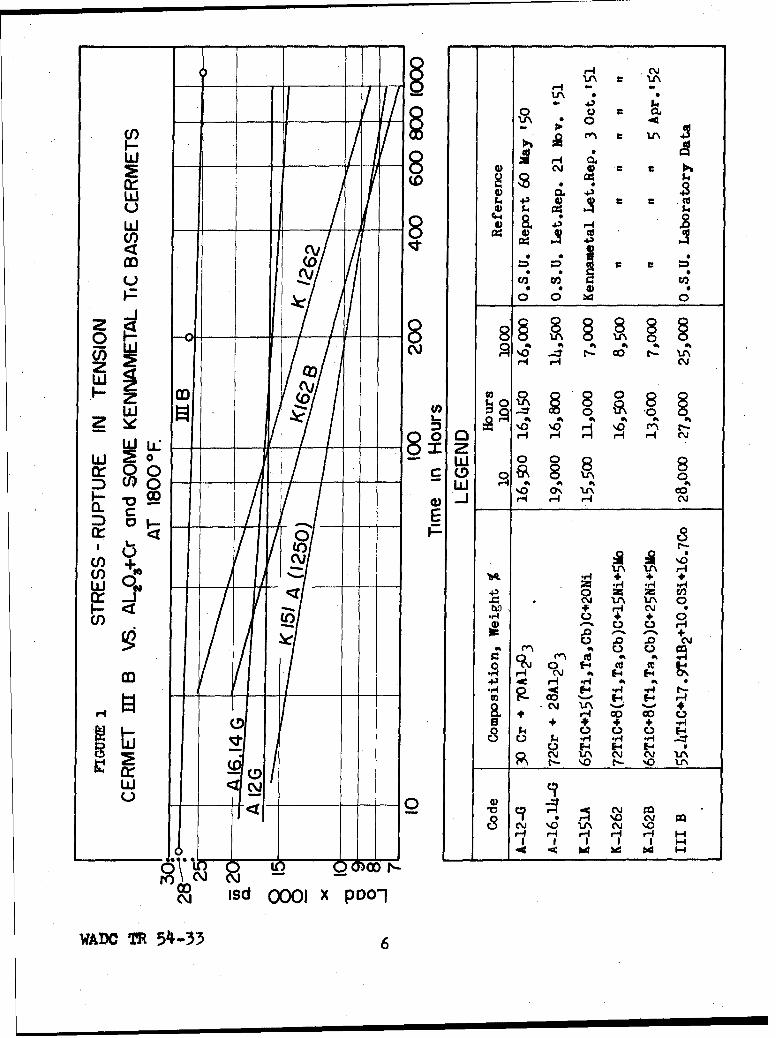
The final stress-to-rupture data at 1800OF for this cermetare shown in Table II and the stress-to-rupture curve is shownin Figure 1. For comparison there are shown in this same
1 A. Rief Blackburn and Thomas S. Shevlin: Equipment for Process-
in& and Testing Cermet Solid Bodies. J. Am. Ceram. Soc., Nov.,1949.
WADC TR 54-333

figure the curves for two chromium - alumina cermets andfor three Kennametal TiC base cermets.
TABLE II
Stress-Rupture Strengths in Tension at 1800OF
Test Stress, Time to RemarksNo. psi failure
117 28,000 1.5 minutes Broke in the neck118 27,000 202 hours "i
WADC* 25,000 2,700 Broke outside neck115 22,000 1,058 " "114 20,000 1,253 " ""
* This rod tested by Materials Laboratory, Directorate ofResearch, WADC.
NOZZLE BLADES
Solid nozzle blades of a simulated airfoil shape conformingto Air Materiel Command drawing X51D9692 were fabricated ofcomposition III B and sintered in a new furnace conforming inall respects to the furnace used for sintering the tensile-testrods.
Thin bar specimens of this composition displayed good heat-shock resistance in laboratory tests but when the solid nozzleblades were subjected to the present standard cycling test atthe Power Plant Laboratory, Directorate of Laboratories, WADC,they failed completely in the first few cycles.
LAs the study of this composition progressed it was deter-mined that, as the end product of sintering, the cobalt isconverted entirely to cobalt monosilicide. The fact that inthb sintered product there is no metal left, as such, but isreplaced by a brittle silicide which serves as the binderphase, may explain why this composition is not resistant toheat-shock.
DISCUSSION WITH RESPECT TO CERMET III B
This composition first attracted favorable attention becauseit is a cermet with a TiC base which is remarkably resistantto high-temperature oxidation by virtue of a borosilicate glassskin which develops on the surface upon heating in an oxidizingatmosphere.
WADC TR 54 -33

Further development disclosed excellent short-time tensilestrengths to 2200OF and a stress-rupture curve at 1800OF higherand flatter than the curves for any other known cermet. Nozzleblades of this composition failed in standardized thermal cyclingtests. It is also anticipated that these blades will be brittlebecause they contain no ductile metal phase.
Continuing research will undertake to get a sufficient metalcontent into this composition to overcome its present deficiencieswithout too Preat a sacrifice in high-temperature strength,particularly stress-rupture strength.
WADO TR 54-33 5
HC
-- * 0
N , M
w I I I 0)v 0.:cn, 8e o
w <
10 . b4 0
0 --- 8N ~ A\ -1 rl- ca t- uN
0 J H- H- c'.J
z co
Lai H 0 0
0 1. Ho H' H (Vj
I. I, 0
a o -- 0D %0 Nco
U)J 1ft .r4 + + 0,
0. r4 r
(1) ~ ~~-') HzV a . -
-- -\ 14 1-
(n N + C;
.,-4 Af r( .0 4c H - -4
~vS ~ o r' 'o 0.r
_ _9 0) C. C4 -
(V IO tP j (V l in
,NC\ N
N~~~' in OO p
WADO TR 54"-33 6
SECTION II
HIGH-TEMPERATURE VACUUM X-RAY CAMERA
A high-temperature x-ray camera was built to permit astudy of the phases present in carbide base cermets at gasturbine engine operating temperatures or other significanthigh temperatures.
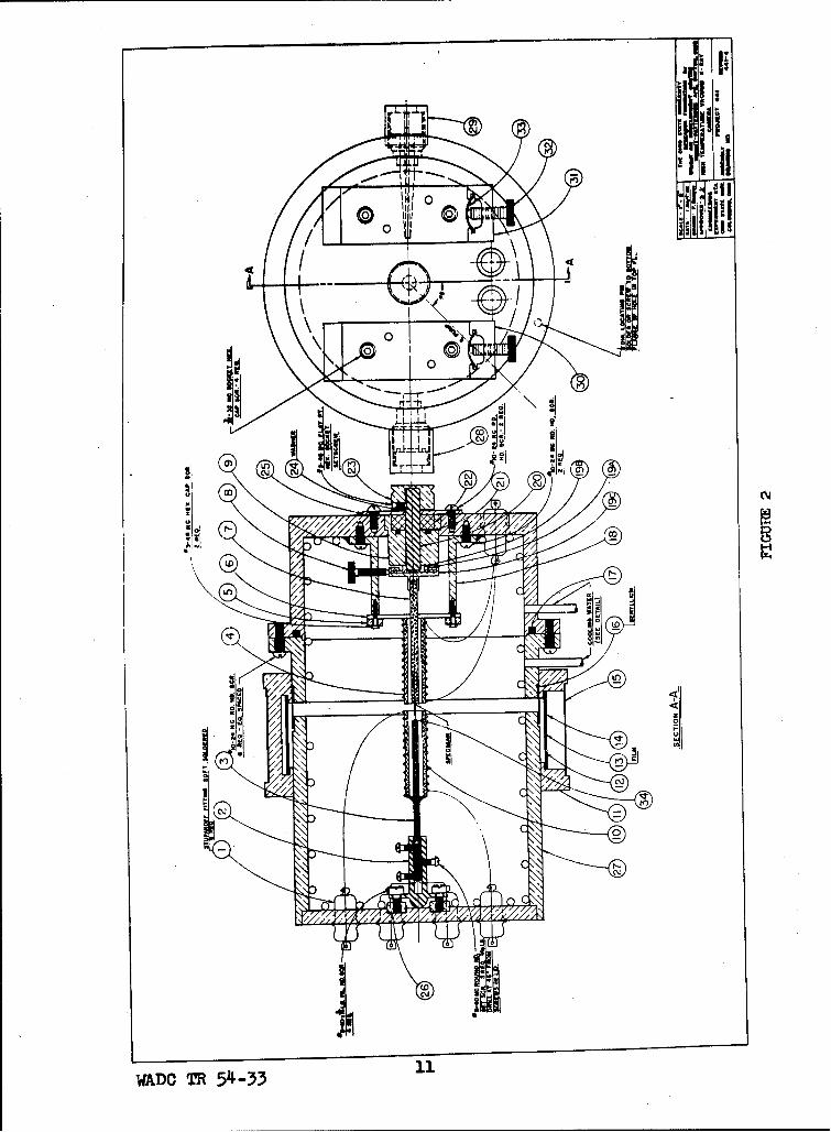
Drawing No. 441-4l, Figure 2, is the assembly drawingof the camera. It is essentially a 114.6 mm powder camerautilizing thin rod specimens which rotate slowly. Theoperating temperature range of this camera is from roomtemperature to 2732 0 F (15000C).
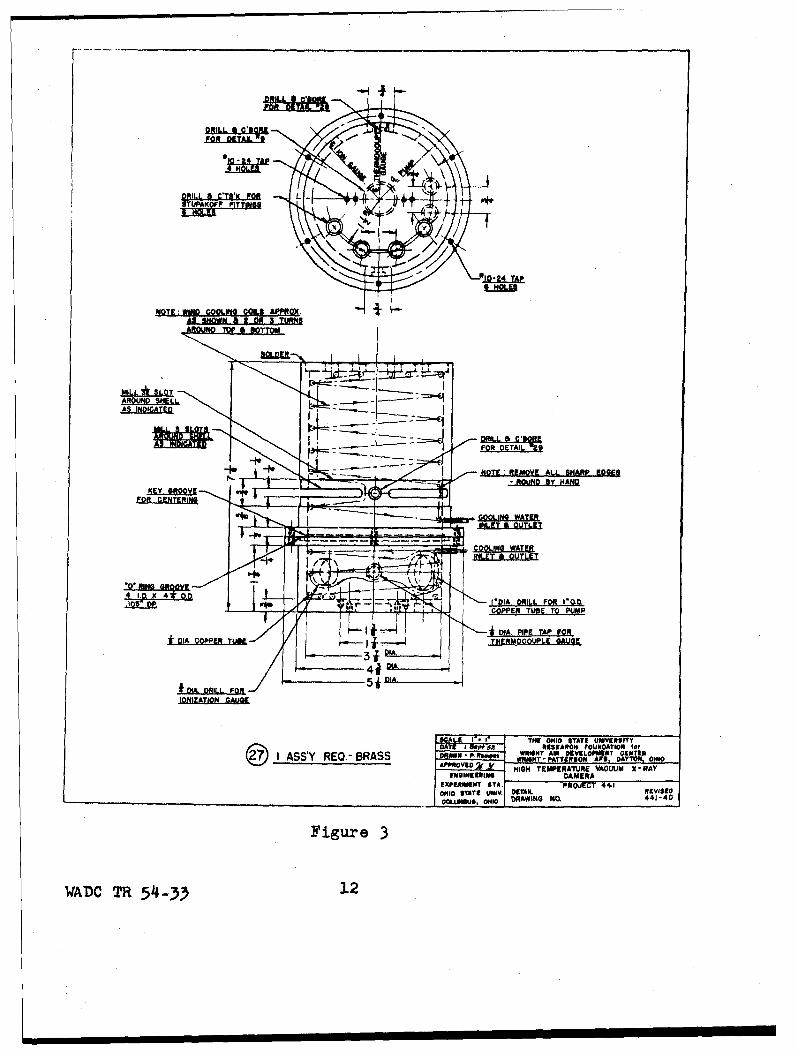
The brass case, Detail No. 27, Figure 3, consists ofan upper and a lower half. The lower half was machined inone piece. The upper half was made in two parts, the cylin-der with the flange being one part and the top plate beingthe other. The cooling coil in the upper half also consistsof two parts, the coil on the inside of the cylinder and thecoil attached to the top plate. All cooling coils were soft-soldered in place. The top plate was soldered in placeconcurrently with the Joining of the two cooling-coil sections.
The furnace, Detail No. 10, Figure 4., consists of twoidentical parts which are connected in series outside thecamera. A suspension of alumina in water was used to paintover the platinum wire windings to about 1/8-inch thickness.
Beryllium foil windows, Reference No. 16, Figure 2,are used in the camera. Low-vapor-pressure hard black wax(Apiezon W) was used to cement the beryllium foil windowsto the brass case and experimentation under vacuum indicatesthis cementing medium to be satisfactory.
The film holder, Detail No. 11, Figure 5, slides overthe outside of the camera. The film holder can be removedwithout affecting the vacuum or the temperature, therebypermitting the photographing of the same sample at differenttemperatures without the necessity of shutting down theapparatus each time.
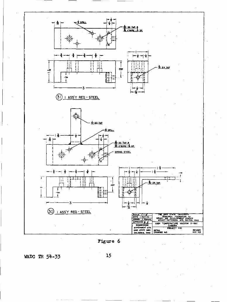
The collimator, Detail No. 29, Figure 4 is of thecircular pinhole type, while the beam-trap, Detail No. 28,Figure 4, is simpler and different from the usual type inthat it does not extend inward to the sample. This simpledesign is possible because in a vacuum there is no scatteringof the x-ray beam by air or other gasses.
WADC TR 54-33 7

The vacuum is obtained using a 1403 Welsh mechanicalpump and a two-inch National Research Corp. (NRC) oildiffusion pump. The vacuum is measured using a NRC 501thermocouple gauge and a NRC 507 ionization gauge. Asingle NRC combination thermocouple and ionization controlcircuit is used with these gauges.
A Pt, Pt-Rh thermocouple, Reference No. 34, Figure 2, is
used to measure the temperature.
Operation of the Camera
Operation of this camera and accessories indicates thatall major difficulties have been overcome and that it willoperate successfully. Before heating the platinum-wireresistange furnace, the camera was evacuated to a pressureof ixl0-O mm Hg. When this furnace was heated, even atthe rapid rate of 900°F per hour, the first outgassing didnot cause the pressure to rise above 5xi0"5 mm Hg. At 20000F(10930C) the cooling coils kept the temperature of theberyllium-foil window, as well as the entire camera, wellbelow room temperature. The Apiezon "W" wax kept theberyllium-foil window vacuum tight, and at 2000OF the pressuredid not rise above lxlO'5 mm Hg.
The camera furnace was originally wound with 31-gaugeplatinum wire. At 20000F it drew 3.5 amperes at 35 volts.When we proceeded to raise the temperature above 20000F thewinding of the upper half of the furnace burned out. Thismay have been due to some flaw in the wire or to too light agauge, and not to contamination of the wire by the cementcovering it, since only 100% A1203 was used with no binderof any kind. A 26-gauge platinum + 20% rhodium wire wasused for the new winding. It is of some interest to notethat after the burn-out it took about one hour for the fur-nace temperature to reach approximately room temperature.It is of considerable interest to note that after the firstthorough outgassing, a vacuum of 5xi0"7 mm Hg could bemaintained.
It was originally planned to calibrate the Pt, Pt-Rhthermocouple against the thermal expansion of MgO. Calcula-tions indicated that this method of temperature calibrationwould be unsatisfactory as the thermal expansion of MgO isknown with insufficient accuracy for this purpose. Calibra-tion could be made using the known melting points of puremetals. It is our opinion that the accuracy of the thermo-couple is sufficient for the present intended purposes.
The identification of new phases as well as the deter-mination of the amount of solid solution in the system Ti +metal at elevated temperatures necessitates preliminary
WADO TR 54-33 8

high temperature x-ray work. This involves the separatedetermination of the thermal expansion of TiC and of themetal. These data must be known so they can be correlatedwith the high temperature x-ray data for the cermet underinvestigation.
WADC TR 54-33 9

Reference Numbers - Figures 2, 3, 4P, 5 and 6
1. Stupakoff Fittings - 6 required2. Steel holder for alumina thermocouple tubing3. 2 hole alumina thermocouple tubing4. Alumina sample holder5. Brass plate - 2 required6. Alumina tubing - 2 required7. Alumina rod8. Thumb screw9. Brass bushing for Garlock seal and shaft10. Platinum wire-resistance furnace11. Film holder12. Black paper13. Film14. Brass sheet15. Brass sheet16. Beryllium foil 0.012 inch thick17. "0" Rings - (1/8" W) 4" 1.0. x 4'1/4" O.D.18. Brass Post - 2 required19. Holder for centering sample20. Steel shaft21. "0" Ring - (1/16" W) 1/2" I.D. x 5/8" O.D.22. Garlock Klozure, Model 51, Part #51X386323. Pulley24. Washer25. Brass plate26. Brass ring27. Brass Shell28. X-ray beam-trap assembly29. Collimator assembly30. Base support---beam-trap end31. Base support---collimator end32. Thumb screws - 2 required33. Steel springs - 2 required34. Pt, Pt-Rh thermocouple
WADC TR 54-33 10
c lii
OD C14
0 C\
WADC TR 54l-33 1
DRILL. ,, CTK FoR L -(i4 -J+---} e*
NOTE:WINO COOLEIG 0O.5 APPROX. ,AS SNOMN SI 2 OR 3 TURNS
ML*IL LOAROUND S"ELAS INDCATED
101 DETA1. •
I,-NOTE ;REMOVE ALL SHARP EDGEG S, ROUND Oty HANDv
I'VIA. DRILL FOR I1R.bCOPPER TB OPM
DIA. PIPE TAP fORf*I ---.FRML THERMOCOUPLE GAUGE
IONIZATION GALO&E
A A A 1 I THE 0"10 STATE UNIVERSITV
DA RESEARH FOUNDATION for
ASS'Y REQ -BRASS DRAWN P m. m WRIA.-NT AW DEV LT 0519 OAPPROVED . HIGH TEMPERATURE VACUUM X-RAY
ENGINEERINm CAMERAEXPEREIINT $TA. PROJECT4, 4OHIO *TATE UNIV. 0TAhIL ReVISIDOGiMUMHS. 0OH4O DRAWING NO. 441-4D
Figure 3
WADC TR 54-33 12

lp I
!' I Il
i1*-
IS4
v .- 0 L" .__,,.• ®
"WA"C TR 54-"

APPROX. .000 THICK
14+
® I REQ.- BRASSD 0t°I ER I - 0TH END$
I I V pTAPPROX. .006 THICH
441
14+
I REQ.-BRASS
i- IT T THE OHIO SLTATE UNIVERSITY52 RESAWC POIJNDATION 1,,A W I RITLf DEVELOPMENT CENTEnQJ)~~~~I ASYRE.- RSSAPRVDPATTEIUON API, DAYTON, OHIO
ýASSY RQ. BRAS APROV0 1_kHIGH TEMPERATURE VACUUM X -RAYENSISEERviH CAMERA________
EXPERIMENT ST.PROJECT 441OHIO STATE UNIV DETAIL REVISEDCOL.UMBUS, OHIO DRAWING NO. 441- 4G.
Figure 5
WADC TR 54-33 14
-. 1, URI, L(tlIII I t
II " -. III III• -
I ASS'Y REQ.- STEEL
20 TAP
I •_• • ••P.
/SPRING STEEL
L+
-~ rl1 ~ I~I l ~ 24 TAP
•, • ,Iii ~ li
3
I ASS'Y REQ.- STEEL THE SDATE I 5.•epI" ot RESEARCH FOUNDATION for
DRAWN P. Rp WRIGHT AIR DEVELOPMENT CENTERDRAWN -WRIGHT- PATTERSON AFR, DAYTON, OHIOAPPROVED 2, HIGH TEMPERATURE VACUUM X-RAY
ENGINEERING CAMERAEXPERIMENT TA.' PROJECT 441O0O STATE UWV. OfAx. REVISEDCOLUMRUS, oHIO DRAWING NO. 441-40
Figure 6
WADC TR 54-33 15

SECTION III
VACUUM QUENCH FURNACE
A furnace was designed and built to permit heatingspecimens in vacuo and then quenching them in vacuo forthe purpose of freezing any high-temperature phasev andsignificant physical characteristics.
Drawing No. 441-5, Figure 7, shows the vacuum quenchfurnace and accessories. For purposes of description itmay be considered as consisting of the furnace, the heatingchamber, the quenching system, the vacuum system, and thetemperature control system.
The vertical split-type furnace contains a firingzone 4.5 x 4.5 x 6.0 inches, appropriately insulated anddesigned for service to 25000Y. It is resistance heatedby means of four standard Globar elements. These are ina series circuit with an electrical power source whichwas readily available. The split feature was incorporat-ed to facilitate loading, making the specimen supportassembly and the heating chamber removable as a unit.
The heating chamber is a MoDanel refractory porcelaintube. This is sealed to the specimen support assembly atthe top and to the vacuum pumping system at the bottom,through the use of "0" rings. The convenient removal andreplacement of the tube, necessary in the loading ofspecimens, is thus provided for.
The quenching system is shown in the detail of Figure7. It consists of a cuenching receptacle and a specimensupport-release device. The quenching receptacle is adrilled copper block resting on a water-cooled support,which may or may not contain a liquid quenching medium.However, common practice is-to use vacuum-pump oil withinthe receptacle. One to four specimens may be supportedin the furnace at one time and can be dropped into thereceptacle independently. Each specimen, provided witha bail, is supported by threading the bail over a finetungsten wire stretched between the common lead and oneof the four electrically insulated leads located aroundthe common lead. These leads are 0.050-inch molybdenumwire. The electrically insulated wires are contained infine alumina tubes from the end in the hot zone of thechamber to near the end which emerges from the fixtureat the top of the chamber. A vacuum seal is effected byembedding the ends of these tubes and the protruding wiresin Apiezon "W" wax at the point where they emerge from thefixture. The common lead is uninsulated and is connected
WADC TRm 5-33 16

to the fixture built up from a standard wrought-copper tee.It is positioned in the hot zone by attachment to a two-holethermocouple insulating tube which is centrally located.The wires of the supporting system are positioned relativeto one another by their manner of mounting in the coppertee fixture at the top of the McDanel tube.
Any one specimen can be dropped by fusing the wire overwhich its bail is hung. This is done by passing a suffi-ciently heavy current through the supporting tungsten wire.
The vacuum system is made up of vacuum pumps, gauges,and the heating chamber. The pumping system consists of aDistillation Products Industries MC275 oil diffusion pumpbacked by a Welch 1403B mechanical pump. Three vacuum gaugesare used. A McLeod gauge is used for intermittent measure-ment of the pressure in the forearm of the diffusion pump,a thermocouple gauge is used to follow the pressure changesnear the throat of the diffusion pump during boiler heat-up, and a Philips gauge is used to measure the pressure atthe copper tee fixture on top of the heating chamber, duringoperation at low pressure. This location of the Philipsgauge was selected so that the pressure measured during opera-tion would be the highest permanent gas pressure in the system.The gauge is mounted in the tubulation seal attached to thecopper tee fixture. This fixture, in conjunction with theheating chamber, completes the closed vacuum system.
Titanium chips are located in the hot zone of the tubewhich serves as the heating chamber for the specimens,These chips are used as a getter for the permanent gasesoxygen and nitrogen which may be present in small amounts.In one sense they may be considered a part of the pumpingsystem.
The temperature control system consists of the powertransformer, a bank of resistors, sensing thermocouple, anda Foxboro control-point controller. Manual setting or adjust-ment of the three power-regulating components allows anydesired temperature up to approximately 2500OF to be main-tained for long periods of time. To establish and controlat a given temperature, the desired temperature is set onthe control-point controller. Power is increased manuallyover a period of time by advancing the setting of the powertransformer until slightly more power is supplied than isrequired to maintain the control temperature with thefurnace at equilibrium. At this time the sensing couplesignals the control instrument which activates a switchplacing power-dissipating resistors in series with thetransformer and the furnace. These can be adjusted to dissi-pate approximately 10% of the power supplied by the trans-former. When the furnace temperature falls below the controlpoint, the instrument, signaled by the sensing couple, again
WADO TR 54-33 17

activates the switch and shunts the series-connected resistorsso that all the power available from the transformer isapplied to heat the furnace. This temperature control systemmight appear to require anticipators to smooth out thefluctuations accompanying signalling and response. However,the specific heat and insulating effects of the tube, and thevacuum within the tube which is used as the heating chamber,are so effective in stabilizing the temperature of the speci-mens that a check thermocouple with its Junction in themidst of these specimens indicates no temperature fluctuation.
In operation, four specimens provided with bails aresupported on four wires stretched between the common leadand each of the four surrounding leads. The system is assembled,the gauges are mounted, and the vacuum pumps started. Thefurnace is brought to temperature and allowed to equilibrateat the control point which has routinely been 2000"F. After atime lapse, usually 24 hours or longer, one or morespecimensore dropped by fusing the support wire, using a 110-voltsource at less than 15 amperes. To do this, the groundedsupport fixture serves as the terminal for the common lead,and the appropriate independently insulated lead serves asthe other terminal. The specimen drops into the quenchingreceptacle.
As pointed out earlier, the selected operating tempera-ture is usually 20000F, and this can be controlled veryclosely in the vicinity of the specimens. Fluctuations,being so small as to be undetectable with the ordinary port-able laboratory potentiometer, are believed to be less thanlop.
Pressures of 2xl0"5 mm Hg are maintained at 2000OF as amatter of routine. These are measured at the tabulation sealshown in Figure 7.
Two methods of dropping the specimens have been used:(1) by slowly melting the supporting wire with a graduallyincreasing current, and (2) by vaporizing the wire with adirect application of full current. The first method isless positive, in that the wire may fuse through at one pointbut still support the specimen. The second method ispositive and preferred. The resulting deposition of vaporizedmetal within the heating chamber may prove to be a disadvantage,but so far has not proven troublesome.
02eration of the Furnace
A vacuum of 2xi0-5 mm Hg can be maintained when thefurnace is at 20000Y. Although this vacuum results in anoxygen pressure of less than lxlO-5 mm Hg, there is sufficient
MAM TR 54 -3 3

oxygen passing through the system in a 24-hour period to forma very thin oxide layer on a polished specimen being heldat temperature. Calculations taking into account the pressure
,in the system and the pumping speed of the oil diffusion pumpagree with the experimental evidence. A static helium atmos-phere was used in the hope of reducing the total oxygen contentso that no oxidation could take place. Results indicate thatmore oxidation takes place when using helium than when using avacuum. Therefore, the furnace will be used in conjunctionwith the vacuum system and a titanium getter will be insertedin the furnace to react preferentially with the small amountof oxygen that enters the system.
The specimen finally adopted is a disc 3/8 inch in dia-meter by 3/16 inch thick, polished on one face. After beingheld at temperature for the desired period of time, the sampleis quenched by dropping it into the water-cooled cup contain-ing diffusion pump oil. To determine the efficiency of quench-ing in oil, five identical specimens of Kennametal compositionK152B were heat-treated and quenched as follows:
(1) Sample heated to 20000F in vacuum, held there42 hours, and quenched in oil.
(2) Sample heated to 2000OF in vacuum, held there42 hours, and allowed to cool with the furnace.
(3) Sample heated to 20000F in air, held there42 hours, and quenched in oil.
(4) Sample heated 200001 in air, held there 42hours, and quenched in salt water.
(5) Sample heated to 20000F in air, held there42 hours, then removed from the furnace andallowed to cool in air.
Results indicate that for specimens held at temperaturefor 42 hours the method of quenching has no effect on theresulting microstructure of the cermet. At the moment neitherthe method nor the speed of quenching appears to be significant.
These 42-hour samples were investigated metallographioallygiving results as follows:
J lJ No distinct new phase has appeared.No change in the carbide grain size was found.(3) No rounding of the carbide grains was noted.(4) The nickel phase appears more mottled.
WAD T 54-3 19

There is some mottling of the nickel phase before theoermet has undergone any heat treatment, but this effect ismuch more pronounced after heat-treating and quenching..Further investigations will be conducted to determine whatcauses this mottled appearance.
WAD• TR 5-33 20
' , , i i i i i i ii i i iI I I

|
Hinges
SIOKVA Vocable Tronsformer
--"" , .060molybdenum•lr'• i • • lit v• pt-Rh wres!@'-- .r•o.,..•• ng
" i• Ap4zon type W., Waxib --'""'- wrought Copper 'T'
J-- • ....... Joint
OieepatcqlRsmetors
------- 7 • ° I €-------------' Tubulohon
tlJ-ve • •) NRC type 1304
Swhen open • high
;j•ll•'• rHlits l!)oclrl sr when closed
-- • • , ," ,• ,. , ".• FoxhOrO Control Instrument
wire brsld "" • "" '• "''• Thsrmoc•4)le€onnector meulotmg tubing \
streps •'•'Pt W. Pt-nh
Tl•srmocouple TI chips
porc:elom tube sooted.top Ik hot, tn 1:)'rlflge
AN-III?-8ICog•... mocouple /
insulating tubing 4.vd•Alumlnl tuboe
US .4, W"" C-IS insulating flrebrlo#
l'oa lidos, I' top and bO•. I-*4 --
"-.- €:- I0 u•lSUlO •lfl g firebrickIre'on oil sides
m
r-
r- • •'• . Vocuum goge
4- I0• blockI I .. Illsore ,xlx"l "s" pipe legs 'r°n connlct;n •
S• Wster €ooled lupport"• E•• l
for
J• I ,u,•.•,•u. •.•.
21

SECTION IV
NEW APPARATUS FOR THE DETERMINATION OF COEFFICIENTSOF THERMAL CONDUCTIVITY AT TEMPERATURES TO 17000F
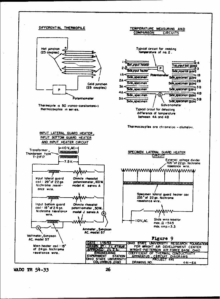
The apparatus, shown in Drawing No. 441-6, Figure 8,built to determine the coefficients 8f thermal conductivityof specimens at temperatures to 1700 F, makes use of astandard specimen and an unknown specimen. It consists ofan input heater unit, a system of guard heaters, a through-put water calorimeter, a system of thermocouples for temp-erature measurement, and a number of variable externalresistors for temperature control. Drawing No. 441-6A,Figure 9, shows the electrical wiring diagram for theapparatus and the circuits for the thermocouples.
The standard specimen, whose thermal conductivity isknown, and the unknown specimen, whose thermal conductivityis to be determined, are cylinders 1.0 inch in diameter and 5.0Inches long. They are joined end to end by a thin slurry ofalumina cement to form a composite specimen 1.0 inch in dia-meter by 10.0 inches long. The joint between the top of thespecimen and the calorimeter is Wood's metal.
The input heater unit consists of 15 inches of 24-gaugenichrome resistance wire wound as a toroid coil embeddedin an alumina plaque. The amount of heat that is generatedis controlled by an external dropping resistor in series withthe heater winding. A Simpson ammeter, Model 57, is used tomeasure the current for the purpose of calculating the amountof heat furnished.
An input bottom guard heater also consists of 15 inchesof 24-gauge niohrome resistance wire in an alumina plaque. Itstemperature is controlled by external variable resistors tomatch the temperature of the bottom of the input heater unit.
The input lateral guard heater is made of 29 inches of22-gauge nichrome resistance wire wound on a 1.875-inch O.D.MoDanel refractory porcelain tube. This winding is coveredwith a cement composed of alumina and plastic fire clay. Thetemperature of this heater is matched to that of the sideof the input heater unit by the same method as in the inputbottom guard heater.
A speclmen lateral guard heater also is made of 1.875-inchO.D. McDanel refractory porcelain tube wound with 235 inches of22-gauge niohrome resistance wire and covered with the aluminaand plastic fire clay cement. This continuous winding, however,
SR 54 -33 22

is divided into five equal parts by the addition of fourintermediate taps, permitting the temperature of each individ-ual section to be matched to that of the specimen oppositeit at that point. The temperatures of the sections of thespecimen lateral guard.heater are controlled by a series ofvoltage dividers in parallel with the winding.
The entire assembly is surrounded with a split-typefurnace insulation made of C-20 insulating brick held togetherby a hinged case.
The temperatures of the specimens and the variousheaters are measured and compared by means of chromel-alumelthermocouples. The temperatures at the side and bottom ofthe input heater unit and at points along the specimen corres-ponding to the steps of the specimen lateral guard heater aremeasured. The temperatures of these points are compared withthe temperatures of points on the guard heaters opposite themby connecting together the thermocouples at the two pointsbeing compared'and reading the resulting differential voltage.
The throughput water calorimeter, of the constant-flowtype, is constructed of copper. This calorimeter is used tocheck the amount of heat transmitted through the compositespecimen and to maintain the cold end at room temperature.
Since the temperature difference between the water flowingin and the water flowing out of the calorimeter is small, adifferential thermopile is used to measure this temperaturedifference. This thermopile is composed of 50 Iron-constantanthermocouples connected together so as to multiply by a factorof 25 the actual temperature difference between the two watertemperatures. These thermocouples pass through rubber stopperswhich seat' in copper cups. The sections of the thermocouplesthat are immersed in water are waterproofed by painting acovering of General Electric black air-drying varnish, No. 457,over the bare wires.
Under ideal equilibrium conditions the heat passingthrough the unknown specimen in a given time may be expressedas any one of the following equivalent values:
(1) The heat equivalent of the electricalenergy input at the input heater.
(2) The heat passing through the standardspecimen for which the thermal conduc-tivity is known and for which the temp-erature gradient is measured during test.
(3) The heat absorbed in the calorimeter.
WADO TR 54-33 23

Since K = HU/AAT, and we have three independent measure-ments of H, we can calculate three independent values of Kfrom H, the physical dimensions of the unknown specimens andthe temperature measurements that give AT. Thus, three valuesof thermal conductivity which should check one another areobtained as a result of measurements made under a single equilib-rated heat-flow condition.
WADC TR _54-33 24

Hinge
NOTE:hspti heater unit,
spec-men lateral guard
NOTE: heater,and lower port
Scale of assembly of throughput colori-
6%l'-0" meter ore packed with
SScore of detoil Si-O-Cell powder12;~ l- O" when assenbled.
NOTE:Colorimeter and
.thermopile coveredwith fib•rous inslation. Throughput Water
___...._ _ _Calorimeter
fxf angle ironToroidol input
Differential Thermopile col
"'Rubber hose I!-I
l6g. s-heet couplings
_ Li,..tDifferential Input Heater Unit
Class 20Sc~o,;?o-III --
refractory Input lateral Input bottom
insuloton guard coil guard coil
Specimen Lateral Input Bottom 8h Lateral
Guard Heater Guard Heater
"DATE : 1 /5 STATE IVERSITY RESEARCH FOUND IN* u FOR WRIGHT AIR DEVELOPMJT CENTERL, --- WRIGHT- PATTRO AIR- FORCE BASE, OHIO
XPEF~tMRNT STT EF OF THERMAL~ CONDUCTIVITY APPAR~rU
Figure 8 &w UT U IT DRAWING PROJECT 441 441-6
WADC TR 5 4-33 25
DIFFERENTIAL THERMOPILE TEMPERATURE MEASURING ANDCOMPARISON CIRCUITS
Hot juncthn Typical crcuit for rtdKing(25 couples),., te ,ature of no. 2.
"2 /2A
Cold junction 2A"dJc~-S&AePw-j w- Zx B(25 couples) 3A -
Si d,,Ac, men SXe,spwecmn 3 a
~otntmee 5~ 58
Thermopile is 50 Iron(+)-constontoeml-) S Galvanometerthermocouples in series. Typical crcuit for detecting
difference of temperaturebetween 4A and 48
Thermocouples ore chromel(÷) - olumelf-).
INPUT LATERAL GUARD HEATER.INPUT BOTTOM GUARO HEATER
AND INPUT HEATER CIRCUIT
Transformer, 11 ... ACThordorson typer,1D SPECIMEN LATERAL GUARD HEATER
T-21FI7 CIRCUIT
7.5 V-- External voltage divider705"of 22go. Nichrome
Input lateral guard Ohnute rheostat
coil: 29*of 229 p Aotentmometer, ImOWNichrome resist- model K series A
once wire. ;:4MiSpecmen lateral cuard heater CENE
o Nc235"Of 22Wgo. NichromEreisstance wOre.
Nnhoerssac oe iecoil1: 15'*of 24 go. potentiometer ,50W.
wire. Ir o C ld ierssoS" max.0 = 54.5
AmmeterM Son pson
AC. model 57Voltmeter, SimpsonAC. model 57 Figur'e 9J~ ~ ~ ~ N S l 11 TATIE UNIVERSITY RESEARC FOUNDATION
Men hooter coil * IS" "R FOR WRIGHT AIR DEVELOPMENT CENTERof 24g0. Nichrome WRIGHT- PATTERSON AIR FORCE BA•g 10EPRMN APARTU .*i T DIAGRAMS
WAD~o T 54-33 2

SECTION V
STUDY OF PHASES AND MICROSTRUCTURE OF TIC+Ni CERMETS
As stated in the introduction, one of the principalphases of this year's program was a study of phase changesor changes in microstructure with time at high temperatures,which might explain the steep slope of the stress-to-rupturecurves for the Kennametal type of TiC base cermets.
The high-temperature vacuum x-ray camera was built toobtain diffraction patterns of the phases present at engineoperating temperatures, for comparison with phases presentat normal atmospheric temperatures, and also to determineif solid solution of TIC in Ni is taking place at thesetemperatures.
The vacuum quench furnace was built so specimens mightbe heated in vacuo at high temperatures and quenched invacuo to freeze any significant phase changes produced bythe combination of temperature and time. It also servesthe purpose of freezing the microstructure of these heat-treated specimens for study by use of the metallograph.Where grain growth occurs it is important to know whetherthe observed grain size was present in the hot specimen orwhether the grain growth occurred during cooling.
As discussed in the section of this report dealingwith the vacuum quench furnace, no new phase was found inquenched specimens which had been heat-treated 42 hours at20000F. This was also found to be true for specimens heat-treated for 200 and 300 hours. This practically eliminatesthe possibility of any new stable phase in these specimenswhile still in the hot condition. The determination ofx-ray diffraction patterns at high temperatures has there-fore been held in abeyance until further fundamental dataare assembled which will permit an evaluation of TiC insolution in the nickel. The x-ray diffraction pattern ata given high temperature will show an expanded crystallattice due to thermal expansion. In addition, there willbe a change in the lattice dimensions if there is anysubstitutional solid solution taking place. The amountof solution can be measured quantitatively assuming asubstitution of Ti atoms for Ni atoms in the nickel. Itis first necessary, however, to determine separately thethermal expansion of TiC and of Ni at the selected temp-erature.
WADC TR 54-33 27
With respect to grain growth, the freezing of specimensheat-treated for varying lengths of time at 2000OF assuresthat grain size shown in photomicrographs of polished sectionsof the quenched specimens o rresponds exactly with the sizeof the grains while at 2000F7.
Studies were conducted on Kennametal compositions K151Aand K152B. Figures 10 and 11 are photomicrographs of K151Aand K152B as originally sintered and before they had undergoneany heat treatment. It will be noted that the carbide grainsare discrete and angular, and the nickel phase shows a littlemottling. Figure 12 is a photomicrograph of K152B after aheat treatment of 42 hours at 2000OF in vacuum followed byquenching in oil. The carbide grains have remained discreteand angular but the mottled appearance of the nickel hasincreased considerably. X-ray diffraction studies of thissample show that it is still a two-phase system, with neithersolution of the carbide in the nickel nor the presence ofany nickel in the carbide. This seems to indicate that themottling in the nickel is due to fine grains or a fineprecipitate of TIC. Greater resolution of the mottled nickelis not possible with visual optics, and plans are being madeto investigate this structure under the electron microscope.
Figures 13 and 14 show specimens of these two compositionsheat-treated 100 hours at 20000F in vacuo and quenched in oilin vacuo. Figure 13 especially shows the carbide grains in theprocess of coalescing. Boundary lines still show where theoriginal grains are in contact. The electron microscope will beused to study the nature of this incipient interfacial bond.
Figure 15 is a photomicrograph of a specimen of K151Awhich, for another investigation, had been heat-treated in airfor 764 hours at 2000OF and not quenched. This picture showsa very pronounced growth of the carbide grains by coalescing,and a squeezing out of the nickel into large lakes.
20000F rather than 18000F was selected as the temperaturefor heat-treating in order to accelerate the significant changestaking place when specimens are heated for long periods of time.It is assumed that the same changes take place at 1800OFthough probably not at the same rate. The preliminary investi-gations completed this year indicate strongly (1) that nosignificant phase changes occur in the subject specimens duringheating for long periods of time at 18000F or at 20000F, but(2) that significant grain growth does occur by coalescing ofthe TiC grains into large carbide masses, probably through themechanism of solution of TiC in the nickel and reprecipitationon the larger TIC grains. At the same time the nickel issqueezed out into large interstitial lakes.
WADC TR 5 4-33 28

Further work must be done to confirm the data and theideas presented here in preliminary form. Samples will beheat-treated for longer times, and all samples will beinvestigated metallographically, by x-ray diffraction andwith the electron microscope. In addition, cermet III Bwill also be investigated in an identical manner so that wemay compare its microstructure with that of K151A and K152B.
A reasonable explanation of the steep slope of the stress-rupture curve for this material is as follows. The coalescingof the carbide grains and the creation of large nickel lakescauses a decrease in the carbide - metal Interfacial area.This results in a decrease in the number of carbide-to-metalbonds, and an increase in the number of metal-to-metal bonds.The metal-to-metal bond is very weak at high temperatures, asis evidenced by the steep stress-rupture curves for metals.The structure formed by the coalescing of TiC grains at 2000OFis not nearly so strong as that formed at the sintering temp-erature of the cermet (Approx. 30000F) because of the incom-plete bonding at this relatively low temperature. Althoughthe bond strength between carbide molecules is a constant,independent of the sintering temperature, the bondingstrength between grains is proportional to the number ofcarbide-to-carbide bonds formed, the latter being a functionof the sintering temperature. It is therefore presently believ-ed that the weakening of the K152B body at 18000F results fromthe fact that a decrease in the number of strong carbide-to-metal bonds and an increase in the number of weak metal-to-metal bonds, with only a relatively small increase in thenumber of strong carbide-to-carbide bonds, produce an over-alldecrease in the bond strength in the body.
WAD( TR 54-33 29

-Figure 10. Kennametal K151A as sintered inproduction. Unetched. Max. resolution at2000X.
Figure 11. Kennametal K152B as sintered inproduction. Unetched. Max. resolution at2000X.
30WADO TR 54-33

Figure 12. K152B heat-treated 42 hours *t2000°F in vacuo and quenched in oil in vaouo.Unetched. Max. resolution at 2000X.
Figure 13. K151A heat-treated 100 hours at2000oF in vacuo and quenched in oil in vaouo.Unetohed. Max. resolution at 2000X.
WADC TR 54-33 31

Figure 14. K152B heat-treated 100 hours at20000F in vacuo and quenched in oil in vaouo.Unetched. Max. resolution at 2000X.
Figure 15. KISIA heat-treated 764 hours at20000F in air and cooled in air at 750F.Unetched. Max. resolution at 2000X.
WADC TR 54-33 32
SECTION VI
PRELIMINARY INVESTIGATION Of TiB2 AND MoSi 2AS THE CERAMIC COMPONENT OF A CERMET
Investigations of hot-pressed MoSi by NACA have indicatedthat this materoal has good strength ang excellent oxidationresistance, Work done in this laboratory on sintered MoSi 2resulted in strength and oxidation data which agreed very wellwith the data for hot-pressed MoSi 2 . Although thismaterial isvery brittle, it was thought, because of its excellent oxidationresistance, that it might be used in conjunction with some metalor alloy in the synthesis of a high-temperature material, or inconjunction with TiB2 as a ceramic base which could be metalbonded.
There were two general plans of investigation:
(1) Metal-bonding of MoSi 2 to improve its ductility.
(2) Adding MoSi 2 to some component such as TiB2 tomake an oxiiation-resistant base which could thenbe metal bonded; sources of both boron and siliconbeing needed to form a borosilicate glass in thesintered product.
1. MATERIALS
The following materials were used:
MoSi 2 : Minus 100 mesh containing 63.44% Mo, 36.45% Si, 0.17%impurities; Electro Metallurgical Division of UnionCarbide and Carbon Corp.
TiB : Minus 20 mesh containing 66.51% Ti, 31.1% B, 1.7%total C, 0.69% minor impurities (1.2% estimated freeC); Norton Company.
CO: Minus 300 mesh, 97.5% Co; Charles Hardy.
Ni: Minus 300 mesh, 99% Ni; Charles Hardy.
Cr: Minus 325 mesh, 98% Cr; Charles Hardy./
2. COMPOSITION/
The following compositions were investigated initially:
2 NACA Research Memorandum E50F22 August 1950.
WADO TR 54-33 33

A. Metal Bonded MoSi 2 :70% MoSi 2 + 30% Cr70% MoSi 2 + 30% Ni70% MoSi 2 + 30% Co
B. TiB2 * MoSi 2 Base:80% TiB2 + 20% MoSi 2
3. FABRICATION
(a) Metal Bonded MoSi 2
The MoSi 9 was milled alone for 24 hours in a hardenedsteel mill using cobalt-bonded tungsten carbide slugs andbenzene as the vehicle. All compositions were wet-mixed inbenzene and then oven dried. Compositions were formed intobars and re-pressed hydrostatically. Separate lots of thesebars were fired at 2500oF and at 27000F in a helium atmos-phere with a one-hour soak at temperature.
(b) TiB2 + MoSi2 Base
The MoSi 2 and TiB2 were milled separately for 24 hoursin a hardened steel mill using cobalt-bonded tungsten carbideslugs and benzene as the vehicle. The MoSi 2 and TiB2 were thenwet mixed together in benzene and oven dried. Small pelletswere formed and re-pressed hydrostatically. These pellets werefired at 25000F, 27000F, and 2900oF in a helium atmosphere witha one-hour soak at temperature.
4. FACTUAL DATA
(a) Metal Bonded MoSi 2
The MoSi 2 + Ni and MoSi 2 + Co compositions producedporous bars with very little strength. The maximum modulus-of-rupture was 10,000 psi but most of the bars could be brokeneasily in the hand. These poor results were due to silicideforming reactions between the MoSi 2 and the Ni or Co. Althoughthe reaction between MoSi and Cr was not as great as with Nior Co, the bars were still very porous and the maximum modulus-of-rupture in this case was only 14,000 psi. These poor resultsdid not warrant the further testing of these compositions.
(b) TiB2 + MoSi 2 Base
Pellets of 80% TiB2 + 20% MoSi 2 fired at 25000F and at27000F were very porous (20-30 percent), The firing at 29000Fresulted in a porosity of 2.0 to 3.0 percent. These latterpellets were tested for oxidation resistance at 2000°F bymeasuring the weight gain due to oxidation. The oxidation
WADC TR5 -33 34

resistance was excellent; the oxidation parameter K inmg 2 /cm4/min was 0.001 after 100 hours, and over 90% of thegain in wdight took place during the first 24 hours. Verylittle or no volatile oxide is produced. This is comparableto MoSi 2 alone and considerably better than SiC.
The next step was to press and sinter bars of the compo-sitions shown in Table TII. These bars were sintered in
,helium at 29000F. All showed excellent oxidation resistanceat 20000F. The porosities and strengths are shown in TableIII.
TABLE III
Strength of TiB2 + MoSi 2 Compositions
Composition Sintering Temp., Apparent Modulus of% OF., held 1 hr. porosity,% rupture, psi
80 TiB2 + 20 Meal2 2900 6 34,00090 " .10 2 2900 16 42,50095 " + 5 " 2900 12 32,000
These porosities indicated that a higher firing temperaturemight be desirable to get maximum strength. Additional barsof 90% TiB2 + 10% MoSi 2 were made and fired in the inductionfurnace in a helium atmosphere at 3150OF held for 1 hour. Theaverage modulus-of-rupture was 70,000 psi. While the porositydecreased to somewhat less than that of the specimens fired at290001, the 3150OF specimens were still porous. Further firingsof the 90% TIB2 4 10% MoSi 2 composition failed to reproduce the70,000 psi modulus-of-rupture. All subsequent moduli of rupturewere less than 50,000 psi.
While no phase diagram has been developed for TiB2 - MoSi 2 ,it is known that there Is a chemical reaction at about 7 to 8percent of MoSi 2 which presumably accounts for the porosity ofmixtures of these two components when larger percentages of MoSi 2are present.
It has been found that the 95% TiB2 + 5.0% MoSi 2 compositioncan be sintered dense with an apparent porosity Lsso than 0.5%over a reasonable range of temperature and still consistentlyshow cold moduli of rupture of over 50,000 psi. It was thereforedecided to concentrate first on the metal bonding of this compo-sition since it is oxidation resistant and appears to be the morepromising ceramic component for a cermet body. Work on the metalbonding of this composition with nickel, cobalt, and chromiumhas been started, but as yet the optimum firing temperatures havenot been determined,
WADO TR 54-33 35