Catalog LV 10.1 · 2013, Chapter 12 - sotuu.net LV 10.1 · 2013 12 12 For further technical product...
42
Siemens LV 10.1 · 2013 12 12 For further technical product information: Service&Support Portal: www.siemens.com/lowvoltage/ technical-support → Product List: Technical specifications → Entry List: Updates / Downloads / FAQs / Manuals / Operating instructions / Characteristic curves / Certificates 12/2 Introduction Transfer switches 12/5 3KC ATC5300 transfer control devices Monitoring devices for electrical values 12/9 5SV8 residual current monitors 12/12 5TT3 voltage relays 12/16 5TT3 current relays 12/18 5TT6 priority switches 12/19 5TT3 fuse monitors 12/20 5TT3 phase and phase sequence monitors 12/21 5TT3 insulation monitors for industrial applications 12/22 7LQ3 monitors for medical premises Monitoring devices for plants and equipment 12/29 5TT3 fault signaling units 12/30 5TT5 EMERGENCY STOP modules 12/31 5TT3 level relays 12/33 5TT3 line circuit relays 12/34 5TT3 p.f. monitors 12/35 5TT3 motor protection relays Charging infrastructure for electric vehicles 12/36 CM-100 charging controllers acc. to IEC 61851 12/38 CM-230 charging controllers acc. to IEC 61851 12/39 5TT3 charging units Monitoring Devices © Siemens AG 2013
Transcript of Catalog LV 10.1 · 2013, Chapter 12 - sotuu.net LV 10.1 · 2013 12 12 For further technical product...

Siemens LV 10.1 · 2013
12
12
For further technical product information:
Service&Support Portal:www.siemens.com/lowvoltage/technical-support
→ Product List: Technical specifications
→ Entry List: Updates / Downloads / FAQs /Manuals / Operating instructions / Characteristic curves / Certificates
12/2 Introduction
Transfer switches12/5 3KC ATC5300 transfer control
devices
Monitoring devices for electrical values
12/9 5SV8 residual current monitors12/12 5TT3 voltage relays12/16 5TT3 current relays12/18 5TT6 priority switches12/19 5TT3 fuse monitors12/20 5TT3 phase and phase sequence
monitors12/21 5TT3 insulation monitors for industrial
applications12/22 7LQ3 monitors for medical premises
Monitoring devices for plants and equipment
12/29 5TT3 fault signaling units12/30 5TT5 EMERGENCY STOP modules12/31 5TT3 level relays12/33 5TT3 line circuit relays12/34 5TT3 p.f. monitors12/35 5TT3 motor protection relays
Charging infrastructure for electric vehicles
12/36 CM-100 charging controllers acc. to IEC 61851
12/38 CM-230 charging controllers acc. to IEC 61851
12/39 5TT3 charging units
Monitoring Devices
LV10-1_12_EN.book Seite 1 Freitag, 15. Februar 2013 11:06 11
© Siemens AG 2013
Monitoring Devices
Introduction
12/2 Siemens LV 10.1 · 2013
12
■ Overview
Devices Page Application Standards Used in
Non
-res
iden
tial
bui
ldin
gs
Res
iden
tial
bui
ldin
gs
Ind
ustr
y
Transfer switches3KC ATC5300 transfer control devices
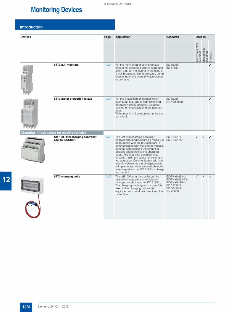
12/5 The 3KC ATC5300 transfer control device, equipped with two motor-driven circuit breakers, serves as a transfer system that automatically or manually switches between two power supply systems in low-voltage power distribu-tion applications.
IEC 60947-6-1; VDE 0660-114
✓ ✓ ✓
Monitoring devices for electrical values5SV8 residual current monitors 12/9 To increase system availability and
operating safety through continuous monitoring of residual current in electri-cal systems and signaling if a defined threshold is exceeded.
IEC 62020; EN 62020 ✓ -- ✓
5TT3 voltage relays 12/12 Monitoring the voltage of emergency lighting in public buildings, short-time failures of 20 ms, for ensuring opera-tional parameters for devices or system components or monitoring the neutral conductor for breaks.
IEC 60255; EN 62020 ✓ -- ✓
5TT3 current relays 12/16 Monitoring of emergency and signal lighting and motors.
All current relays can be short-time overloaded and connected either with direct measurement or through trans-formers.
IEC 60255 ✓ -- ✓
5TT6 priority switches 12/18 For a reduction of the connection fee in accordance with German Federal Reg-ulations on Tariffs when used in systems with electric storage heaters where the continuous-flow heaters are switched with priority.
IEC 60669; BTO § 6 Section 4
-- ✓ --
5TT3 fuse monitors 12/19 Monitoring of all types of low-voltage fuses.
Can be used in asymmetric systems afflicted with harmonics and regenera-tive feedback motors.
IEC 60255 ✓ -- ✓
LV10-1_12_EN.book Seite 2 Freitag, 15. Februar 2013 11:06 11
© Siemens AG 2013
12
Monitoring Devices
Introduction
12/3Siemens LV 10.1 · 2013
Devices Page Application Standards Used in
Non
-res
iden
tial
bui
ldin
gs
Res
iden
tial
bui
ldin
gs
Ind
ustr
y
5TT3 phase and phase sequence monitors
12/20 For the visual signaling of phase failures or phase sequences in three-phase systems.
The phase sequence is arbitrary. The device is also suitable for 1, 2 or 3-phase operation.
IEC 60255 -- -- ✓
5TT3 insulation monitors for indus-trial applications
12/21 To increase system availability and operating safety through continuous monitoring of the isolation resistance in non-grounded direct voltage or AC volt-age systems.
IEC 60255;IEC 61557
-- -- ✓
7LQ3 monitors for medical premises
12/22 For the insulation monitoring of a medical IT system or the load current monitoring of an IT system transformer for a non-permissible temperature rise.
Monitoring of the voltage supply with automatic switchover.
EN 61557-8; IEC 61557-8; DIN VDE 0100-710; IEC 60364-7-710
✓ -- --
Monitoring devices for plants and equipment5TT3 fault signaling units 12/29 Evaluation and display of fault alarms
and alarm signals for monitoring indus-trial plants and control systems. With 4 inputs and connections for 39 expansion fault signaling units.
IEC 60255 ✓ -- ✓
5TT5 EMERGENCY STOP modules 12/30 For EMERGENCY-OFF switching in accordance with the Directive 98/37/EC on Safety of Machines. Safe types of circuits for machines, plants or test stations in industrial, commercial and private enterprise applications.
According to the Machinery Directive 98/37/EC; EN 954-1
✓ -- ✓
5TT3 level relays 12/31 Control of liquid levels in containers with 3 electrode connections for 1-step and 2-step level control. High immunity to interference of the measuring circuit isolated from the system.
IEC 60255, DIN VDE 0435
✓ -- ✓
5TT3 line circuit relays 12/33 For disconnecting the voltage of unused lines when loads are disabled.
IEC 60255, DIN VDE 0435
-- ✓ --
LV10-1_12_EN.book Seite 3 Freitag, 15. Februar 2013 11:06 11
© Siemens AG 2013
Monitoring Devices
Introduction
12/4 Siemens LV 10.1 · 2013
12
Devices Page Application Standards Used in
Non
-res
iden
tial
bui
ldin
gs
Res
iden
tial
bui
ldin
gs
Ind
ustr
y
5TT3 p.f. monitors 12/34 For the monitoring of asynchronous motors for underload and no-load oper-ation, e.g. fan monitoring in the case of V-belt breakage, filter blockages, pump monitoring in the event of valve closure or dry runs.
IEC 60255, IEC 61557
-- -- ✓
5TT3 motor protection relays 12/35 For the prevention of thermal motor overloads, e.g. due to high switching frequency, single-phasing, disabled cooling or excessive ambient tempera-tures. With detection of wire breaks in the sen-sor circuit.
IEC 60255, DIN VDE 0435
-- -- ✓
Charging infrastructure for electric vehiclesCM-100 / 230 charging controller acc. to IEC61851
12/36 The CM-100 charging controller enables charging in charging mode 3 in accordance with the IEC standard. It communicates with the electric vehicle, controls and monitors the switching devices and identifies the charging cable. The charging controller thus ensures maximum safety for the charg-ing operation. Communication with the electric vehicle via the charging cable is implemented via a pulse-width modu-lated signal acc. to IEC 61851-1 charg-ing mode 3.
IEC 61851-1 IEC 61851-22
✓ ✓ ✓
5TT3 charging units 12/39 The WB100A charging units can be used to charge electric vehicles in charging mode 3 acc. to IEC 61851. The charging cable type 1 or type 2 is fixed to the charging unit and is equipped with residual current and line protection.
IEC/EN 61851-1; IEC/EN 61851-22; IEC/EN 62196-1; IEC 62196-2; IEC 60439-3; DIN 43880
✓ ✓ ✓
LV10-1_12_EN.book Seite 4 Freitag, 15. Februar 2013 11:06 11
© Siemens AG 2013
Monitoring DevicesTransfer Switches
3KC ATC5300 transfer control devices
12/5Siemens LV 10.1 · 2013
12
■ Overview
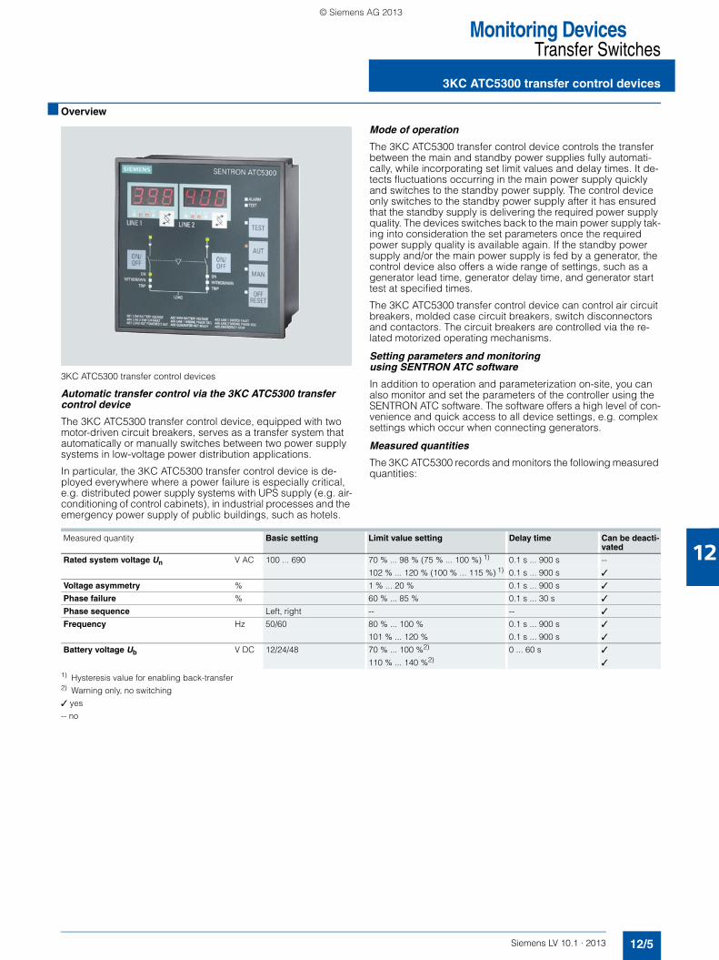
3KC ATC5300 transfer control devices
Automatic transfer control via the 3KC ATC5300 transfer control device
The 3KC ATC5300 transfer control device, equipped with two motor-driven circuit breakers, serves as a transfer system that automatically or manually switches between two power supply systems in low-voltage power distribution applications.
In particular, the 3KC ATC5300 transfer control device is de-ployed everywhere where a power failure is especially critical, e.g. distributed power supply systems with UPS supply (e.g. air-conditioning of control cabinets), in industrial processes and the emergency power supply of public buildings, such as hotels.
Mode of operation
The 3KC ATC5300 transfer control device controls the transfer between the main and standby power supplies fully automati-cally, while incorporating set limit values and delay times. It de-tects fluctuations occurring in the main power supply quickly and switches to the standby power supply. The control device only switches to the standby power supply after it has ensured that the standby supply is delivering the required power supply quality. The devices switches back to the main power supply tak-ing into consideration the set parameters once the required power supply quality is available again. If the standby power supply and/or the main power supply is fed by a generator, the control device also offers a wide range of settings, such as a generator lead time, generator delay time, and generator start test at specified times.
The 3KC ATC5300 transfer control device can control air circuit breakers, molded case circuit breakers, switch disconnectors and contactors. The circuit breakers are controlled via the re-lated motorized operating mechanisms.
Setting parameters and monitoring using SENTRON ATC software
In addition to operation and parameterization on-site, you can also monitor and set the parameters of the controller using the SENTRON ATC software. The software offers a high level of con-venience and quick access to all device settings, e.g. complex settings which occur when connecting generators.
Measured quantities
The 3KC ATC5300 records and monitors the following measured quantities:
1) Hysteresis value for enabling back-transfer2) Warning only, no switching
✓ yes
-- no
Measured quantity Basic setting Limit value setting Delay time Can be deacti-vated
Rated system voltage Un V AC 100 ... 690 70 % ... 98 % (75 % ... 100 %) 1) 0.1 s ... 900 s --
102 % ... 120 % (100 % ... 115 %) 1) 0.1 s ... 900 s ✓
Voltage asymmetry % 1 % ... 20 % 0.1 s ... 900 s ✓
Phase failure % 60 % ... 85 % 0.1 s ... 30 s ✓
Phase sequence Left, right -- -- ✓
Frequency Hz 50/60 80 % ... 100 % 0.1 s ... 900 s ✓
101 % ... 120 % 0.1 s ... 900 s ✓
Battery voltage Ub V DC 12/24/48 70 % ... 100 %2) 0 ... 60 s ✓
110 % ... 140 %2) ✓
LV10-1_12_EN.book Seite 5 Freitag, 15. Februar 2013 11:06 11
© Siemens AG 2013

Monitoring DevicesTransfer Switches
3KC ATC5300 transfer control devices
12/6 Siemens LV 10.1 · 2013
12
■ Benefits
The advantages of the 3KC ATC5300 transfer control device at a glance:• Controls molded case circuit breakers (MCCBs), air circuit
breakers (ACBs), switch disconnectors (LBSs), or contactors• Two measuring inputs for single-phase and multi-phase power
supply systems• Option for switching between system to system, generator to
system, system to generator, and generator to generator con-figurations
• Direct measurement of three-phase industrial systems rang-ing up to 400 V ACL-N or 690 V ACL-L (converter costs, no as-sembly and installation costs for transformers)
• Has two voltage supply units to cover all standard AC/DC volt-age supplies, alternative supply via main and standby system possible
• Low space requirements due to door installation and compact design
• Two displays for monitoring the normal/standby system and displaying the phase and interlinked cable voltages
• Setting control parameters for generator activation require-ments
• Calendar clock• 8 digital inputs, 6 of which are programmable and 7 relay out-
puts, 5 of which are programmable• 4 selectable operating modes: off, manual, automatic, test• Data, parameter and logged events (e.g. power failure, faults)
remain accessible and unaltered even after a power failure or restarting a device
• Status display of the connected switches or contactors• Logging and statistical processing of occurring events possi-
ble • Easy system integration through integrated MODBUS inter-
face (RTU and ASCII) for integrating e.g. into a power man-agement system
• The illuminated LED display makes reading measured values and parameters easy, even in unfavorable lighting conditions
• The SENTRON ATC programming software saves consider-able time when setting parameters and setting up the 3KC ATC5300 transfer control device
• Generator test run function for mandatory testing intervals• Command option for switching to the second set of protection
parameters in the ETU76B (air circuit breaker 3WL).
■ Integration
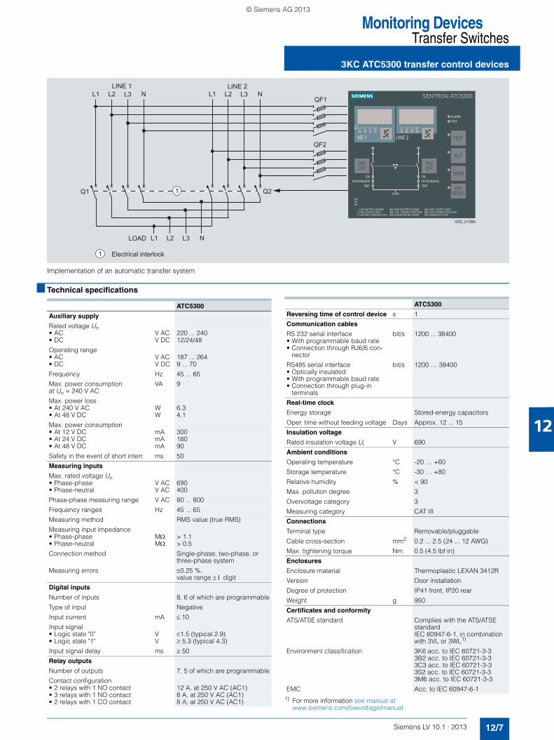
Implementation of an automatic transfer system
The 3KC ATC5300 transfer control device is used to automati-cally and manually switch from a main power supply to a standby power supply and vice versa. In the event that system faults occur, the 3KC ATC5300 transfer control device controls the switching operations fully automatically. This ensures a very high level of operational continuity.
The 3KC ATC5300 transfer control device allows the implemen-tation of an automatic transfer control in conjunction with molded case circuit breakers (MCCBs), air circuit breakers (ACBs), switch disconnectors (LBSs), or contactors.
The following devices are ideally matched to the 3KC ATC5300 transfer control system:• 3VL molded case circuit breakers• 3WL air circuit breakers
Component interaction• Feed-in system line 1 (main system) and line 2 (standby sys-
tem) are connected to the 3KC ATC5300 transfer control sys-tem.
• In case of system anomalies, the 3KC ATC5300 transfer con-trol device activates components Q1 and Q2 accordingly.
• Q1 and Q2 can be implemented with molded case circuit breakers (MCCBs), air circuit breakers (ACBs), switch discon-nectors (LBSs), or contactors
Q1 and Q2, configured with circuit breakers
All SENTRON circuit breakers connected to the 3KC ATC5300 transfer control device must be equipped with the following ac-cessories:• 3VL MCCBs
The following is also required for each MCCB:- One motorized operating mechanism- One alarm switch- Two auxiliary switches 1 NO/1 NC
• 3WL ACBs The following is also required for each 3WL ACB:- One motorized operating mechanism- One closing solenoid- One auxiliary release (shunt release)- One tripped signal switch- One auxiliary switch block 2 NO/2 NC (standard fittings)
LV10-1_12_EN.book Seite 6 Freitag, 15. Februar 2013 11:06 11
© Siemens AG 2013
12
Monitoring DevicesTransfer Switches
3KC ATC5300 transfer control devices
12/7Siemens LV 10.1 · 2013
Implementation of an automatic transfer system
■ Technical specifications
1) For more information see manual at: www.siemens.com/lowvoltage/manual.
x x x x x x x x
1 Electrical interlock
LOAD
LINE 2LINE 1L1 L2 L3 NL1 L2 L3 N
L1 L2 L3 N
Q1 Q2
QF1
QF2
I202_01380
1
ATC5300
Auxiliary supply
Rated voltage Un• AC V AC 220 ... 240• DC V DC 12/24/48
Operating range• AC V AC 187 ... 264• DC V DC 9 ... 70
Frequency Hz 45 ... 65
Max. power consumption at Un = 240 V AC
VA 9
Max. power loss• At 240 V AC W 6.3• At 48 V DC W 4.1
Max. power consumption• At 12 V DC mA 300• At 24 V DC mA 180• At 48 V DC mA 90
Safety in the event of short interr. ms 50
Measuring inputs
Max. rated voltage Un• Phase-phase V AC 690• Phase-neutral V AC 400
Phase-phase measuring range V AC 80 ... 800
Frequency ranges Hz 45 ... 65
Measuring method RMS value (true RMS)
Measuring input impedance• Phase-phase MΩ > 1.1• Phase-neutral MΩ > 0.5
Connection method Single-phase, two-phase, or three-phase system
Measuring errors ±0.25 %, value range ± 1 digit
Digital inputs
Number of inputs 8, 6 of which are programmable
Type of input Negative
Input current mA ≤ 10
Input signal• Logic state "0" V ≤1.5 (typical 2.9)• Logic state "1" V ≥ 5.3 (typical 4.3)
Input signal delay ms ≥ 50
Relay outputs
Number of outputs 7, 5 of which are programmable
Contact configuration• 2 relays with 1 NO contact 12 A, at 250 V AC (AC1)• 3 relays with 1 NO contact 8 A, at 250 V AC (AC1)• 2 relays with 1 CO contact 8 A, at 250 V AC (AC1)
ATC5300
Reversing time of control device s 1
Communication cables
RS 232 serial interface • With programmable baud rate• Connection through RJ6/6 con-
nector
bit/s 1200 ... 38400
RS485 serial interface • Optically insulated• With programmable baud rate• Connection through plug-in
terminals
bit/s 1200 … 38400
Real-time clock
Energy storage Stored-energy capacitors
Oper. time without feeding voltage Days Approx. 12 ... 15
Insulation voltage
Rated insulation voltage Ui V 690
Ambient conditions
Operating temperature °C -20 … +60
Storage temperature °C -30 … +80
Relative humidity % < 90
Max. pollution degree 3
Overvoltage category 3
Measuring category CAT III
Connections
Terminal type Removable/pluggable
Cable cross-section mm2 0.2 ... 2.5 (24 ... 12 AWG)
Max. tightening torque Nm 0.5 (4.5 lbf·in)
Enclosures
Enclosure material Thermoplastic LEXAN 3412R
Version Door installation
Degree of protection IP41 front, IP20 rear
Weight g 950
Certificates and conformity
ATS/ATSE standard Complies with the ATS/ATSE standard IEC 60947-6-1, in combinationwith 3VL or 3WL1)
Environment classification 3K6 acc. to IEC 60721-3-33B2 acc. to IEC 60721-3-33C3 acc. to IEC 60721-3-33S2 acc. to IEC 60721-3-33M6 acc. to IEC 60721-3-3
EMC Acc. to IEC 60947-6-1
LV10-1_12_EN.book Seite 7 Freitag, 15. Februar 2013 11:06 11
© Siemens AG 2013

Monitoring DevicesTransfer Switches
3KC ATC5300 transfer control devices
12/8 Siemens LV 10.1 · 2013
12
* You can order this quantity or a multiple thereof.
■ Selection and ordering data
Version DT Order No. Priceper PU
PU(UNIT,
SET, M)
PS* PG Weightper PU
approx. kg
Screw connection
3KC9 000-8TL30
3KC ATC5300 transfer control devices Control panel instrument 144 x 144 x 94 mm with the following features:
• Screw terminal connection
• AC/DC power supply unit
• 220 … 240 V AC, 45 ... 60 Hz
• 9 ... 70 V DC
• Rated setting range: 100 AC…690 V
3KC9 000-8TL30 1 1 unit 143 1.004
3KC9 000-8TL70
SENTRON ATC software
Software for setting parameters and remote control operations, incl. connection cable from control device to PC,cable length 1.8 m
• CD incl. software and manuals.
• Minimum hardware and software requirements:- Pentium, 64 MB RAM- COM interface (serial RS 232)- CD drive- Windows 95/98/2000/XP/Vista/Windows 7
3KC9 000-8TL70 1 1 unit 143 0.209
LV10-1_12_EN.book Seite 8 Freitag, 15. Februar 2013 11:06 11
© Siemens AG 2013
Monitoring DevicesMonitoring Devices for Electrical Values
5SV8 residual current monitors
12/9Siemens LV 10.1 · 2013
12
■ Overview
Plant safety and operating safety are becoming increasingly im-portant alongside the protection of personnel. Shutdowns due to the unexpected tripping of protective devices cause high costs. It is possible to detect residual currents in the electrical installa-tion before the protective device responds.
Residual current monitors (RCM) monitor residual current in electrical installations and issue a signal when the residual cur-rent exceeds a set value.
RCMs are used primarily in plants where a fault should result in a signal but not in disconnection. This enables plant operators to detect faults and eliminate their causes before the protective de-vices disconnect the installation, which increases plant and op-erating safety and cuts costs.
The summation current transformer detects all conductors re-quired to conduct the current, i.e. including the neutral conduc-tor where applicable. In a fault-free system, the magnetizing ef-fects of the conductors through which current is flowing cancel each other out for the summation current transformer, i.e. the sum of all currents is zero. If a residual current is flowing due to an insulation fault, a residual magnetic field is left in the core of the transformer and produces a voltage. This voltage is evalu-ated using the electronics of the RCM. The switched contact can be used e.g. to operate an acoustic/optical signaling device, a higher-level control system or a circuit breaker.
Time characteristic of the rated residual current ΙΔn
■ Benefits
• Higher plant availability and operating safety through perma-nent monitoring of residual currents
• Adjustable limit values for residual current and response time enable timely detection and signaling – plant shutdowns are often avoidable
• Devices for every application: The summation current transformers are available in various sizes, the RCMs can be used optionally for signaling and/or switching
• Additional fire protection can be implemented using the mon-itoring system
■ Technical specifications
1) INS: instantaneous, SEL: selective.
100 % n
50 %
t
n
nR
esid
ual c
urre
nt
Time
Alarm
Disconnection
I202
_160
44
RCM analog RCM digital RCM digital, 4 channels
Standards EN 62020, IEC 62020Approvals UL
Rated operational voltage Ue V AC 230• Frequency Hz 50/60
Rated residual current ΙΔn• Type A A 0.03 ... 3 0.03 ... 3 0.03 ... 3• Type AC A 3 ... 5 3 ... 30 3 ... 30
Response time tv s 0.02 ... 5 0.02 ... 10, INS, SEL1) 0.02 ... 10, INS, SEL1)
Relay contacts 1 × alarm 1 × alarm, 1 × tripping operation
1 × alarm, 4 × tripping operation
• Rated voltage V AC 230 230 230• Rated current A 6 6 6
Summation current transformer mm ∅ 20 ... 210
Maximum cable length RCM/CT (shielded cable) m 10
Conductor cross-section mm2 1.5
Test/Reset Yes/Yes
External tripping operation/external reset --/Yes Yes/Yes Yes/Yes
Mounting width MW 2 3 3
Degree of protection• Contacts IP20• Front IP41
Operating temperature °C -10 ... +50
LV10-1_12_EN.book Seite 9 Freitag, 15. Februar 2013 11:06 11
© Siemens AG 2013
Monitoring DevicesMonitoring Devices for Electrical Values
5SV8 residual current monitors
12/10 Siemens LV 10.1 · 2013
12
* You can order this quantity or a multiple thereof.
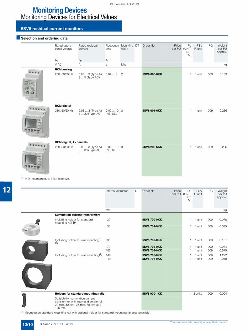
■ Selection and ordering data
1) INS: instantaneous, SEL: selective.
1) Mounting on standard mounting rail with optional holder for standard mounting rail also possible.
Rated opera-tional voltage
Rated residual current
Response time
Mounting width
DT Order No. Priceper PU
PU(UNIT,
SET,M)
PS*/P. unit
PG Weightper PU
approx.
Ue IΔn tv V AC A s MW kg
RCM analog
230, 50/60 Hz 0.03 ... 3 (Type A) 3 ... 5 (Type AC)
0.02 ... 5 2 5SV8 000-6KK 1 1 unit 009 0.163
RCM digital
230, 50/60 Hz 0.03 ... 3 (Type A) 3 ... 30 (Type AC)
0.02 ... 10, INS, SEL1)
3 5SV8 001-6KK 1 1 unit 009 0.236
RCM digital, 4 channels
230, 50/60 Hz 0.03 ... 3 (Type A) 3 ... 30 (Type AC)
0.02 ... 10, INS, SEL1)
3 5SV8 200-6KK 1 1 unit 009 0.236
Internal diameter DT Order No. Priceper PU
PU(UNIT,
SET,M)
PS*/P. unit
PG Weightper PU
approx.
mm kg
Summation current transformers
Including holder for standard mounting rail u
20 5SV8 700-0KK 1 1 unit 009 0.076
30 5SV8 701-0KK 1 1 unit 009 0.095
Including holder for wall mounting1)
u35 5SV8 702-0KK 1 1 unit 009 0.161
70 5SV8 703-0KK 1 1 unit 009 0.274105 5SV8 704-0KK 1 1 unit 009 0.545
Including holder for wall mountingu 140 5SV8 705-0KK 1 1 unit 009 1.222210 5SV8 706-0KK 1 1 unit 009 2.040
Holders for standard mounting rails 5SV8 900-1KK 1 2 units 009 0.004
Suitable for summation current transformer with internal diameter of 20 mm, 30 mm, 35 mm, 70 mm and 105 mm
LV10-1_12_EN.book Seite 10 Freitag, 15. Februar 2013 11:06 11
© Siemens AG 2013
12
Monitoring DevicesMonitoring Devices for Electrical Values
5SV8 residual current monitors
12/11Siemens LV 10.1 · 2013
■ Dimensional drawings
Residual current monitor
Summation current transformer
RCM analog, 5SV8 000-6KK RCM digital, 5SV8 001-6KK, 5SV8 200-6KK
I2_1
1602
7
36
45 67 8544
68654 44
686
I2_1
6028
45 67 85
Summation current transformer, 5SV8 700-0KK Summation current transformer, 5SV8 701-0KK
Type Dimen-sions
A B C D E F G
5SV8 702-0KK 100 79 26 49 35 35 43
5SV8 703-0KK 130 110 32 66 70 52 57
5SV8 704-0KK 170 146 38 94 105 72 73
5SV8 705-0KK 230 196 49 123 140 97 98
5SV8 706-0KK 299 284 69 161 210 141 142
Summation current transformers, 5SV8 702-0KK, 5SV8 703-0KK, 5SV8 704-0KK, 5SV8 705-0KK, 5SV8 706-0KK
I2_116029
Ø46
Ø20
2460
32I2_16030
Ø59
Ø30
3070
32
ØE
G46
6,5
B
F33A
D
8
C
I202_16031
LV10-1_12_EN.book Seite 11 Freitag, 15. Februar 2013 11:06 11
© Siemens AG 2013
Monitoring DevicesMonitoring Devices for Electrical Values
5TT3 voltage relays
12/12 Siemens LV 10.1 · 2013
12
■ Overview
Voltage relays are used for device and plant protection, supply-ing safety light devices and the detection of N-conductor breaks and short-time voltage interruptions.
They are available as undervoltage, overvoltage and un-der/overvoltage relays. The devices are equipped with different functions, depending on their intended use, and comply with the pertinent regulations.
■ Benefits
• Complete voltage protection in a compact design for overvolt-age and undervoltage monitoring in a single device
• Plants and devices are reliably and easily protected by phase-failure relays
• Overvoltages and consequential damage due to high volt-ages are prevented through N-conductor monitoring
• Asymmetry monitoring in the voltage relay also protects three-phase AC motors against operation with voltage skew
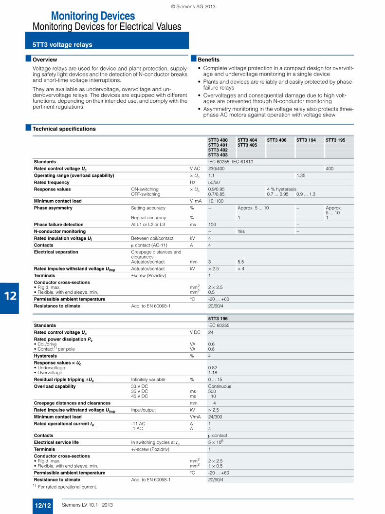
■ Technical specifications
1) For rated operational current.
5TT3 400 5TT3 404 5TT3 406 5TT3 194 5TT3 1955TT3 401 5TT3 4055TT3 4025TT3 403
Standards IEC 60255; IEC 61810
Rated control voltage Uc V AC 230/400 400
Operating range (overload capability) × Uc 1.1 1.35
Rated frequency Hz 50/60
Response values ON-switching × Uc 0.9/0.95 4 % hysteresisOFF-switching 0.7/0.85 0.7 ... 0.95 0.9 ... 1.3
Minimum contact load V; mA 10; 100
Phase asymmetry Setting accuracy % -- Approx. 5 ... 10 -- Approx. 5 ... 10
Repeat accuracy % -- 1 -- 1
Phase failure detection At L1 or L2 or L3 ms 100 --
N-conductor monitoring -- Yes --
Rated insulation voltage Ui Between coil/contact kV 4
Contacts μ contact (AC-11) A 4
Electrical separation Creepage distances and clearancesActuator/contact mm 3 5.5
Rated impulse withstand voltage Uimp Actuator/contact kV > 2.5 > 4
Terminals ±screw (Pozidriv) 1
Conductor cross-sections• Rigid, max. mm2 2 × 2.5• Flexible, with end sleeve, min. mm2 0.5
Permissible ambient temperature °C -20 ... +60
Resistance to climate Acc. to EN 60068-1 20/60/4
5TT3 196
Standards IEC 60255
Rated control voltage Uc V DC 24
Rated power dissipation Pv• Coil/drive VA 0.6• Contact1) per pole VA 0.8
Hysteresis % 4
Response values × Uc • Undervoltage 0.82• Overvoltage 1.18
Residual ripple tripping ΔUc Infinitely variable % 0 ... 15
Overload capability 33 V DC Continuous35 V DC ms 50045 V DC ms 10
Creepage distances and clearances mm 4
Rated impulse withstand voltage Uimp Input/output kV > 2.5
Minimum contact load V/mA 24/300
Rated operational current Ie -11 AC A 1-1 AC A 4
Contacts μ contact
Electrical service life In switching cycles at Ie 5 × 10⁵
Terminals +/-screw (Pozidriv) 1
Conductor cross-sections• Rigid, max. mm2 2 × 2.5• Flexible, with end sleeve, min. mm2 1 × 0.5
Permissible ambient temperature °C -20 ... +60
Resistance to climate Acc. to EN 60068-1 20/60/4
LV10-1_12_EN.book Seite 12 Freitag, 15. Februar 2013 11:06 11
© Siemens AG 2013
12
Monitoring DevicesMonitoring Devices for Electrical Values
5TT3 voltage relays
12/13Siemens LV 10.1 · 2013
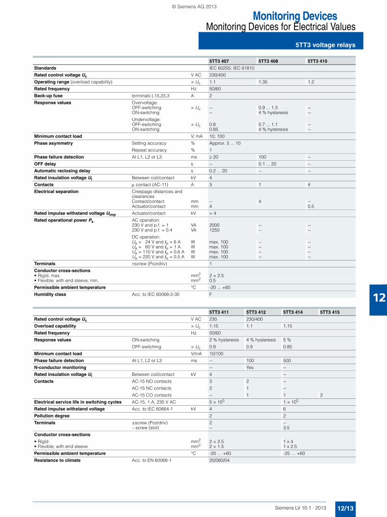
5TT3 407 5TT3 408 5TT3 410
Standards IEC 60255; IEC 61810
Rated control voltage Uc V AC 230/400
Operating range (overload capability) × Uc 1.1 1.35 1.2
Rated frequency Hz 50/60
Back-up fuse terminals L1/L2/L3 A 2
Response values Overvoltage:OFF-switching × Uc -- 0.9 ... 1.3 --ON-switching -- 4 % hysteresis --
Undervoltage:OFF-switching × Uc 0.8 0.7 ... 1.1 --ON-switching 0.85 4 % hysteresis --
Minimum contact load V; mA 10; 100
Phase asymmetry Setting accuracy % Approx. 5 ... 10
Repeat accuracy % 1
Phase failure detection At L1, L2 or L3 ms ≥ 20 100 --
OFF delay s -- 0.1 ... 20 --
Automatic reclosing delay s 0.2 ... 20 -- --
Rated insulation voltage Ui Between coil/contact kV 4
Contacts μ contact (AC-11) A 3 1 4
Electrical separation Creepage distances and clearances Contact/contact mm -- 4 --Actuator/contact mm 4 5.5
Rated impulse withstand voltage Uimp Actuator/contact kV > 4
Rated operational power Ps AC operation:230 V and p.f. = 1 VA 2000 -- --230 V and p.f. = 0.4 VA 1250 -- --
DC operation:Ue = 24 V and Ie = 6 A W max. 100 -- --Ue = 60 V and Ie = 1 A W max. 100 -- --Ue = 110 V and Ie = 0.6 A W max. 100 -- --Ue = 220 V and Ie = 0.5 A W max. 100 -- --
Terminals ±screw (Pozidriv) 1
Conductor cross-sections• Rigid, max. mm2 2 × 2.5• Flexible, with end sleeve, min. mm2 0.5
Permissible ambient temperature °C -20 ... +60
Humidity class Acc. to IEC 60068-2-30 F
5TT3 411 5TT3 412 5TT3 414 5TT3 415
Rated control voltage Uc V AC 230 230/400
Overload capability × Uc 1.15 1.1 1.15
Rated frequency Hz 50/60
Response values ON-switching 2 % hysteresis 4 % hysteresis 5 %
OFF-switching × Uc 0.9 0.9 0.85
Minimum contact load V/mA 10/100
Phase failure detection At L1, L2 or L3 ms -- 100 500
N-conductor monitoring -- Yes --
Rated insulation voltage Ui Between coil/contact kV 4 --
Contacts AC-15 NO contacts 3 2 --
AC-15 NC contacts 2 1 --
AC-15 CO contacts -- 1 1 2
Electrical service life in switching cycles AC-15, 1 A, 230 V AC 5 × 10⁵ 1 × 10⁵
Rated impulse withstand voltage Acc. to IEC 60664-1 kV 4 6
Pollution degree 2 2
Terminals ±screw (Pozidriv) 2 --– screw (slot) -- 3.5
Conductor cross-sections
• Rigid mm2 2 × 2.5 1 x 4• Flexible, with end sleeve mm2 2 × 1.5 1 x 2.5
Permissible ambient temperature °C -20 … +60 -25 … +60
Resistance to climate Acc. to EN 60068-1 20/060/04
LV10-1_12_EN.book Seite 13 Freitag, 15. Februar 2013 11:06 11
© Siemens AG 2013

Monitoring DevicesMonitoring Devices for Electrical Values
5TT3 voltage relays
12/14 Siemens LV 10.1 · 2013
12
* You can order this quantity or a multiple thereof.
■ Selection and ordering data
Contacts Ue Ie Uc Mounting width
DT Order No. Priceper PU
PU(UNIT,
SET, M)
PS*/P. unit
PG Weightper PU
approx.
V AC A V MW kg
Overvoltage relays
5TT3 194
For the monitoring of 1, 2 or 3 phases against N, switching thresholds: 0.9 ... 1.3 × Uc, 4 % hysteresis, adjustable
2 CO 230 4 230/400 AC 2 5TT3 194 1 1 unit 027 0.132
For the monitoring of 3 phases against N, with N-conductor monitoring, switching thresholds: 0.9 ... 1.3 × Uc, 4 % hysteresis, adjustable
2 CO 230 4 230/400 AC 2 5TT3 195 1 1 unit 027 0.132
Direct voltage monitors
5TT3 196
for monitoring a 24-V direct voltage system;undervoltage Ufrom = 0.82overvoltage Ufrom = 1.18residual ripple 0 % ... 15 %, adjustable
1 NO and 1 NC, 230 5 24 DC 1 5TT3 196 1 1 unit 027 0.074
Undervoltage relays
5TT3 400
5TT3 402
5TT4 404
5TT3 414
For the monitoring of 1, 2 or 3 phases against N, with phase failure detection,
• Switching thresholds: 0.7 and 0.9 x Uc, not adjustable
1 CO 230 4 230/400 AC 1 } 5TT3 400 1 1 unit 027 0.081
2 CO 230 4 230/400 AC 2 } 5TT3 402 1 1 unit 027 0.126
• Switching thresholds: 0.9 ... 0.95 ×Uc
2 CO 230 4 230/400 AC 2 5TT3 403 1 1 unit 027 0.126
For the monitoring of 1, 2 or 3 phases against N, with phase failure detection, switching thresholds: 0.85 and 0.95 x Uc, not adjustable
1 CO 230 4 230/400 AC 1 } 5TT3 401 1 1 unit 027 0.079
For the monitoring of 3 phases against N, with asymmetry, reverse voltage and phase failure detection, with N-conductor monitoring
• Switching thresholds: 0.7 and 0.9 x Uc, not adjustable
2 CO 230 4 230/400 AC 2 5TT3 404 1 1 unit 027 0.130
• Switching thresholds: 0.7 ... 0.95 × Uc, 5 % hysteresis, adjustable
2 CO 230 4 230/400 AC 2 5TT3 406 1 1 unit 027 0.131
For the monitoring of 3 phases against N, with asymmetry, reverse voltage and phase failure detection, with N-conductor monitoring, switching thresholds: 0.85 and 0.95 x Uc, not adjustable
2 CO 230 4 230/400 AC 2 5TT3 405 1 1 unit 027 0.128
For the monitoring of 1, 2 or 3 phases against N, switching thresholds: 0.85 x Uc, not adjustableresponse delay 0.5 soff-delay 60 s
1 CO 230 4 230/400 AC 1 5TT3 414 1 1 unit 027 0.070
• with TEST pushbutton
2 CO 230 4 230/400 AC 1 5TT3 415 1 1 unit 027 0.080
LV10-1_12_EN.book Seite 14 Freitag, 15. Februar 2013 11:06 11
© Siemens AG 2013
12
Monitoring DevicesMonitoring Devices for Electrical Values
5TT3 voltage relays
12/15Siemens LV 10.1 · 2013* You can order this quantity or a multiple thereof.
Contacts Ue Ie Uc Mounting width
DT Order No. Priceper PU
PU(UNIT,
SET,M)
PS*/P. unit
PG Weightper PU
approx.
V AC A V AC MW kg
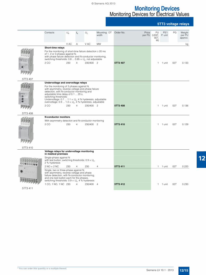
5TT3 407
Short-time relays
For the monitoring of short-time failure detection ≥ 20 ms of 1, 2 or 3 phases against N, with phase failure detection and N-conductor monitoring,switching thresholds: 0.8 ... 0.85 × Uc, not adjustable
2 CO 230 4 230/400 2 5TT3 407 1 1 unit 027 0.133
5TT3 408
Undervoltage and overvoltage relays
For the monitoring of 3 phases against N, with asymmetry, reverse voltage and phase failure detection, with N-conductor monitoring and adjustable time delay of 0.1 ... 20 s, switching thresholds: Undervoltage: 0.7 ... 1.1 × Uc, 4 % hysteresis, adjustable overvoltage: 0.9 ... 1.3 × Uc, 4 % hysteresis, adjustable
2 CO 230 4 230/400 2 5TT3 408 1 1 unit 027 0.136
5TT3 410
N-conductor monitors
With asymmetry detection and N-conductor monitoring
2 CO 230 4 230/400 2 5TT3 410 1 1 unit 027 0.129
Voltage relays for undervoltage monitoring in medical premises
5TT3 411
Single-phase against N with test button, switching thresholds: 0.9 × Un, 2 % hysteresis
2 NO + 2 NC 230 4 230 4 5TT3 411 1 1 unit 027 0.220
Single, two or three-phase against N, with asymmetry, reverse voltage and phase failure detection, with N-conductor monitoring, and one test button each for the phases, switching thresholds: 0.9 × Un, 4 % hysteresis
1 CO, 1 NO, 1 NC 230 4 230/400 4 5TT3 412 1 1 unit 027 0.230
LV10-1_12_EN.book Seite 15 Freitag, 15. Februar 2013 11:06 11
© Siemens AG 2013

Monitoring DevicesMonitoring Devices for Electrical Values
5TT3 current relays
12/16 Siemens LV 10.1 · 2013
12
■ Overview
Current relays monitor single and three-phase systems for the flow of current, e.g. in emergency lighting installations, and the loading of motors. They are available as undercurrent, overcur-rent and under/overcurrent relays.
■ Benefits
• Devices with an extremely broad range of applications of min-imum 0.1 A to maximum 15 A without transformer
• Permanent overload capability up to 20 A or 30 A max. for up to 3 seconds, protect the function against uncontrolled plant states and increase plant availability
• Range changing enables the precise setting of current values through a high resolution
• Ultra compact current relays require only the smallest of space and save costs
■ Technical specifications
5TT6 111 5TT6 112Standards IEC 60255Rated control current Ic A 1 ... 10Rated control voltage Uc V AC 230Primary operating range ×Uc 0.9 ... 1.1Overload capability, continuous A 15Overload capability, short-time At 50 °C ambient
temperature max. 3 sA 20
Rated frequency Hz 50/60Response values ON-switching Infinitely variable
OFF-switching permanent, 4 % hysteresis
Switching delay tv Infinitely adjustable s 0.1 ... 20Response time Non-adjustable ms Current corresponds to the rated operational power of the
continuous-flow heater
Minimum contact load V; mA 10; 100Rated insulation voltage Ui Between coil/contact kV 2.5Contactsμ contact (AC-15) NO contacts A 3
NC contacts A 1
Electrical separation Creepage distances mm 3Actuator/contact
Rated impulse withstand voltage Uimp Actuator/contact kV > 4Terminals ±screw (Pozidriv) 1Conductor cross-sections Rigid max. mm2 2 × 2.5
Flexible, with end sleeve min. mm2 1 × 0.5
Permissible ambient temperature °C -20 ... +60Resistance to climate Acc. to EN 60068-1 20/60/4
5TT6 113 5TT6 114 5TT6 115 5TT6 120
Standards IEC 60255
Rated control current Ic 4 ranges 1 rangeA 0.1 ... 1 0.5 ... 5A 0.5 ... 5A 1 ... 10A 1.5 ... 15
Rated control voltage Uc V AC 230
Primary operating range ×Uc 0.9 ... 1.1Overload capability, continuous A 20 15Overload capab. independ. of measuring range max. 3 s A 30
Rated frequency Hz 50/60
Response values ON-switching Infinitely variableOFF-switching permanent, 4 % hysteresis
Switching delay tv Infinitely adjustable s 0.1 ... 20
Response time Non-adjustable ms see: www.siemens.com/lowvoltage/manual
Minimum contact load V; mA 10; 100
Rated insulation voltage Ui Between coil/contact kV 2.5
Contactsμ contact (AC-15) NO contacts A 5
NC contacts A 1
Electrical separation Creepage distances mm 3Actuator/contact
Rated impulse withstand voltage Uimp Actuator/contact kV > 4
Terminals ±screw (Pozidriv) 1
Conductor cross-sections Rigid max. mm2 2 × 2.5Flexible, with end sleeve min. mm2 1 × 0.5
Permissible ambient temperature °C -20 ... +60
Resistance to climate Acc. to EN 60068-1 20/60/4
LV10-1_12_EN.book Seite 16 Freitag, 15. Februar 2013 11:06 11
© Siemens AG 2013
12
Monitoring DevicesMonitoring Devices for Electrical Values
5TT3 current relays
12/17Siemens LV 10.1 · 2013* You can order this quantity or a multiple thereof.
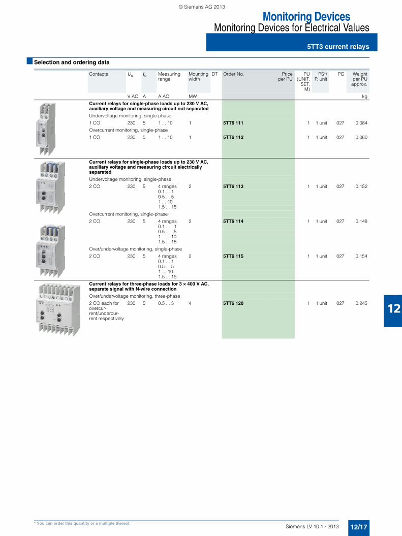
■ Selection and ordering data
Contacts Ue Ie Measuring range
Mounting width
DT Order No. Priceper PU
PU(UNIT,
SET,M)
PS*/P. unit
PG Weightper PU
approx.
V AC A A AC MW kg
Current relays for single-phase loads up to 230 V AC, auxiliary voltage and measuring circuit not separated
Undervoltage monitoring, single-phase
1 CO 230 5 1 ... 10 1 5TT6 111 1 1 unit 027 0.084
Overcurrent monitoring, single-phase
1 CO 230 5 1 ... 10 1 5TT6 112 1 1 unit 027 0.080
Current relays for single-phase loads up to 230 V AC, auxiliary voltage and measuring circuit electrically separated
Undervoltage monitoring, single-phase
2 CO 230 5 4 ranges 2 5TT6 113 1 1 unit 027 0.1520.1 ... 10.5 ... 51 ... 101.5 ... 15
Overcurrent monitoring, single-phase
2 CO 230 5 4 ranges 2 5TT6 114 1 1 unit 027 0.1480.1 ... 10.5 ... 51 ... 101.5 ... 15
Over/undervoltage monitoring, single-phase
2 CO 230 5 4 ranges 2 5TT6 115 1 1 unit 027 0.1540.1 ... 10.5 ... 51 ... 101.5 ... 15
Current relays for three-phase loads for 3 × 400 V AC, separate signal with N-wire connection
Over/undervoltage monitoring, three-phase
2 CO each for overcur-rent/undercur-rent respectively
230 5 0.5 ... 5 4 5TT6 120 1 1 unit 027 0.245
LV10-1_12_EN.book Seite 17 Freitag, 15. Februar 2013 11:06 11
© Siemens AG 2013
Monitoring DevicesMonitoring Devices for Electrical Values
5TT6 priority switches
12/18 Siemens LV 10.1 · 2013* You can order this quantity or a multiple thereof.
12
■ Overview
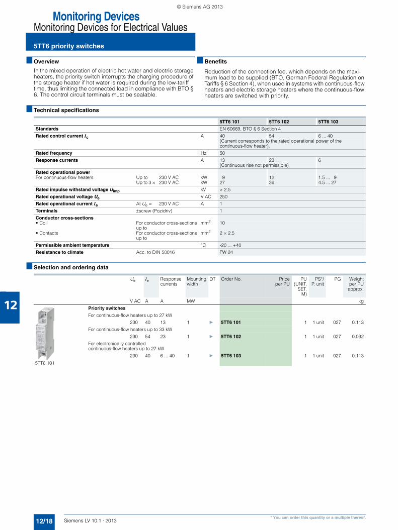
In the mixed operation of electric hot water and electric storage heaters, the priority switch interrupts the charging procedure of the storage heater if hot water is required during the low-tariff time, thus limiting the connected load in compliance with BTO § 6. The control circuit terminals must be sealable.
■ Benefits
Reduction of the connection fee, which depends on the maxi-mum load to be supplied (BTO, German Federal Regulation on Tariffs § 6 Section 4), when used in systems with continuous-flow heaters and electric storage heaters where the continuous-flow heaters are switched with priority.
■ Technical specifications
■ Selection and ordering data
5TT6 101 5TT6 102 5TT6 103
Standards EN 60669, BTO § 6 Section 4
Rated control current Ic A 40 54 6 ... 40 (Current corresponds to the rated operational power of the continuous-flow heater).
Rated frequency Hz 50
Response currents A 13 23 6(Continuous rise not permissible)
Rated operational powerFor continuous-flow heaters Up to 230 V AC kW 9 12 1.5 ... 9
Up to 3 × 230 V AC kW 27 36 4.5 ... 27
Rated impulse withstand voltage Uimp kV > 2.5
Rated operational voltage Ue V AC 250
Rated operational current Ie At Ue = 230 V AC A 1
Terminals ±screw (Pozidriv) 1
Conductor cross-sections• Coil For conductor cross-sections
up tomm2 10
• Contacts For conductor cross-sections up to
mm2 2 × 2.5
Permissible ambient temperature °C -20 ... +40
Resistance to climate Acc. to DIN 50016 FW 24
Ue Ie Response currents
Mounting width
DT Order No. Priceper PU
PU(UNIT,
SET,M)
PS*/P. unit
PG Weightper PU
approx.
V AC A A MW kg
5TT6 101
Priority switches
For continuous-flow heaters up to 27 kW
230 40 13 1 } 5TT6 101 1 1 unit 027 0.113
For continuous-flow heaters up to 33 kW
230 54 23 1 } 5TT6 102 1 1 unit 027 0.092
For electronically controlled continuous-flow heaters up to 27 kW
230 40 6 ... 40 1 } 5TT6 103 1 1 unit 027 0.113
LV10-1_12_EN.book Seite 18 Freitag, 15. Februar 2013 11:06 11
© Siemens AG 2013
12
Monitoring DevicesMonitoring Devices for Electrical Values
5TT3 fuse monitors
12/19Siemens LV 10.1 · 2013* You can order this quantity or a multiple thereof.
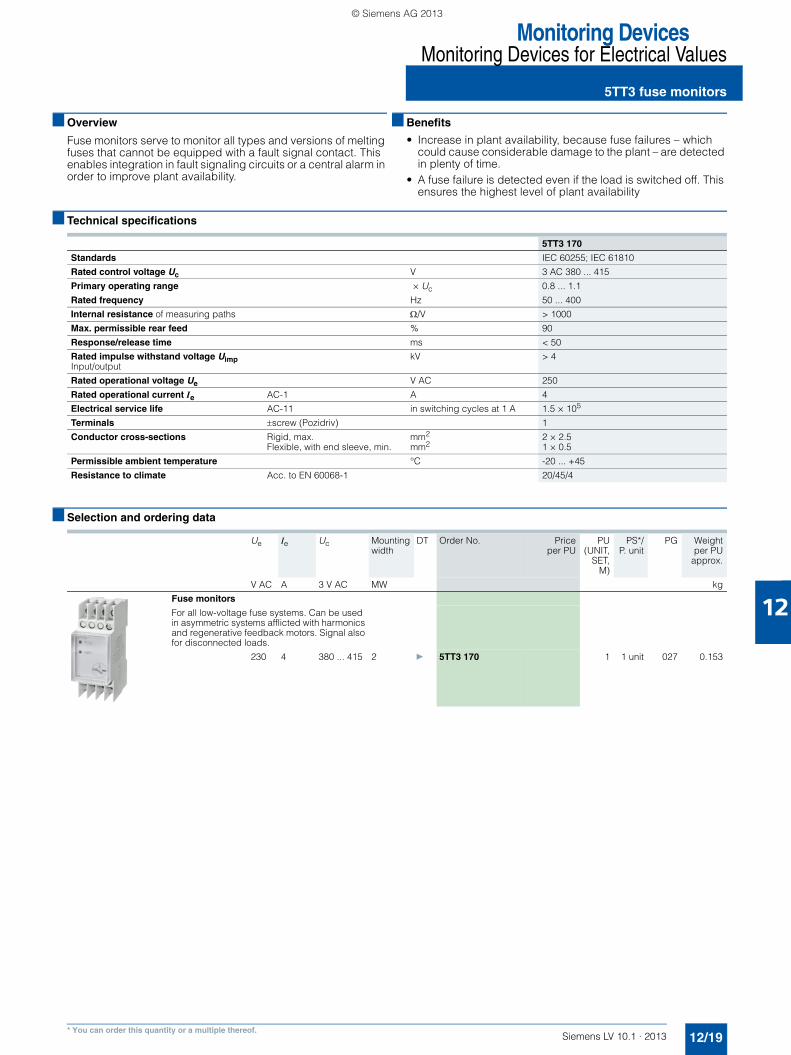
■ Overview
Fuse monitors serve to monitor all types and versions of melting fuses that cannot be equipped with a fault signal contact. This enables integration in fault signaling circuits or a central alarm in order to improve plant availability.
■ Benefits
• Increase in plant availability, because fuse failures – which could cause considerable damage to the plant – are detected in plenty of time.
• A fuse failure is detected even if the load is switched off. This ensures the highest level of plant availability
■ Technical specifications
■ Selection and ordering data
5TT3 170
Standards IEC 60255; IEC 61810
Rated control voltage Uc V 3 AC 380 ... 415
Primary operating range × Uc 0.8 ... 1.1
Rated frequency Hz 50 ... 400
Internal resistance of measuring paths Ω/V > 1000
Max. permissible rear feed % 90
Response/release time ms < 50
Rated impulse withstand voltage UimpInput/output
kV > 4
Rated operational voltage Ue V AC 250
Rated operational current Ie AC-1 A 4
Electrical service life AC-11 in switching cycles at 1 A 1.5 × 10⁵
Terminals ±screw (Pozidriv) 1
Conductor cross-sections Rigid, max. mm2 2 × 2.5Flexible, with end sleeve, min. mm2 1 × 0.5
Permissible ambient temperature °C -20 ... +45
Resistance to climate Acc. to EN 60068-1 20/45/4
Ue Ie Uc Mounting width
DT Order No. Priceper PU
PU(UNIT,
SET,M)
PS*/P. unit
PG Weightper PU
approx.
V AC A 3 V AC MW kg
Fuse monitors
For all low-voltage fuse systems. Can be used in asymmetric systems afflicted with harmonics and regenerative feedback motors. Signal also for disconnected loads.
230 4 380 ... 415 2 } 5TT3 170 1 1 unit 027 0.153
LV10-1_12_EN.book Seite 19 Freitag, 15. Februar 2013 11:06 11
© Siemens AG 2013

Monitoring DevicesMonitoring Devices for Electrical Values
5TT3 phase and phase sequence monitors
12/20 Siemens LV 10.1 · 2013* You can order this quantity or a multiple thereof.
12
■ Overview
Phase monitors monitor the voltages in three-phase system and signal the power failure of one or more phases over a floating contact. Phase sequence monitors monitor the phase sequence in three-phase systems and signal any changes in the phase se-quence – change of rotating field – over a floating changeover contact.
■ Benefits
• The three-phase LED display in the phase monitor and the LED display in the phase sequence monitors provide constant information on the switching state of the plant
• The compact design in 1 MW saves space
■ Technical specifications
■ Selection and ordering data
5TT3 421 5TT3 423
Standards IEC 60255
Rated control voltage Uc V AC 230/400 400
Primary operating range ×Uc 0.8 ... 1.1
Rated frequency Hz 50/60
Rated power dissipation Pv Electronics VA 9Contacts VA 0.2
Rated operational voltage Ue V AC 250
Rated operational current Ie A 4
Minimum contact load V; mA 10; 100
Rated insulation voltage Ui Between coil/contact kV 4
Contacts μ contact (AC-11) A 3
Electrical separation Creepage distances and clearancesActuator/contact mm 4
Rated impulse withstand voltage Uimp Actuator/contact kV > 2.5
Terminals ±screw (Pozidriv) 1
Conductor cross-sections Rigid, max. mm2 2 × 2.5Flexible, with end sleeve, min. mm2 --
Degree of protection Acc. to EN 60529 IP20, with connected conductors
Safety class Acc. to EN 61140/VDE 0140-1 II
Permissible ambient temperature °C -20 ... +60
Resistance to climate Acc. to EN 60068-1 20/60/4
Contacts Ue Ie Uc Mounting width
DT Order No. Priceper PU
PU(UNIT,
SET,M)
PS*/P. unit
PG Weightper PU
approx.
V AC A V AC MW kg
Phase monitors
With 3 green LEDs for 3 phases
1 CO 250 4 230/400 1 } 5TT3 421 1 1 unit 027 0.080
Phase sequence monitors
With one green LED, which lights up for right-rotating field
1 CO 250 4 400 1 } 5TT3 423 1 1 unit 027 0.080
LV10-1_12_EN.book Seite 20 Freitag, 15. Februar 2013 11:06 11
© Siemens AG 2013
12
Monitoring DevicesMonitoring Devices for Electrical Values
5TT3 insulation monitorsfor industrial applications
12/21Siemens LV 10.1 · 2013* You can order this quantity or a multiple thereof.
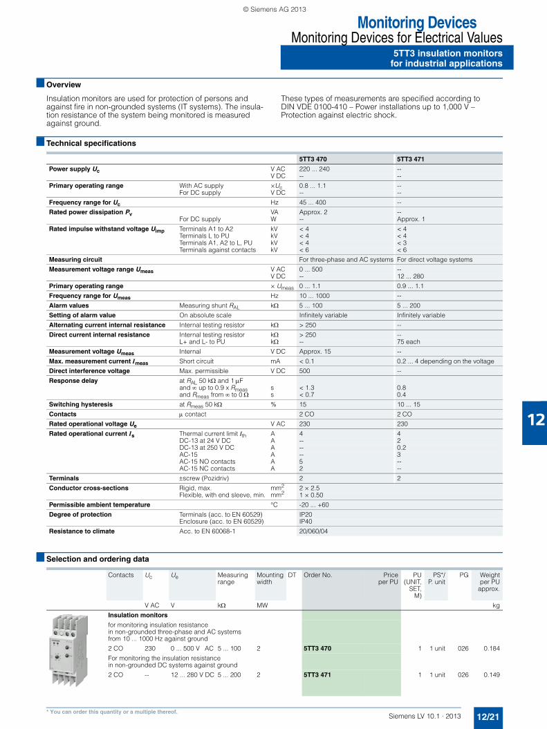
■ Overview
Insulation monitors are used for protection of persons and against fire in non-grounded systems (IT systems). The insula-tion resistance of the system being monitored is measured against ground.
These types of measurements are specified according to DIN VDE 0100-410 – Power installations up to 1,000 V – Protection against electric shock.
■ Technical specifications
■ Selection and ordering data
5TT3 470 5TT3 471
Power supply Uc V AC 220 ... 240 --V DC -- --
Primary operating range With AC supply ×Uc 0.8 ... 1.1 --For DC supply V DC -- --
Frequency range for Uc Hz 45 ... 400 --
Rated power dissipation Pv VA Approx. 2 --For DC supply W -- Approx. 1
Rated impulse withstand voltage Uimp Terminals A1 to A2 kV < 4 < 4Terminals L to PU kV < 4 < 4Terminals A1, A2 to L, PU kV < 4 < 3Terminals against contacts kV < 6 < 6
Measuring circuit For three-phase and AC systems For direct voltage systems
Measurement voltage range Umeas V AC 0 ... 500 --V DC -- 12 ... 280
Primary operating range × Umeas 0 ... 1.1 0.9 ... 1.1
Frequency range for Umeas Hz 10 ... 1000 --
Alarm values Measuring shunt RAL kΩ 5 ... 100 5 ... 200
Setting of alarm value On absolute scale Infinitely variable Infinitely variable
Alternating current internal resistance Internal testing resistor kΩ > 250 --
Direct current internal resistance Internal testing resistor kΩ > 250 --L+ and L- to PU kΩ -- 75 each
Measurement voltage Umeas Internal V DC Approx. 15 --
Max. measurement current Imeas Short circuit mA < 0.1 0.2 ... 4 depending on the voltage
Direct interference voltage Max. permissible V DC 500 --
Response delay at RAL 50 kΩ and 1 μFand ∞ up to 0.9 x Rmeas s < 1.3 0.8and Rmeas from ∞ to 0 Ω s < 0.7 0.4
Switching hysteresis at Rmeas 50 kΩ % 15 10 ... 15
Contacts μ contact 2 CO 2 CO
Rated operational voltage Ue V AC 230 230
Rated operational current Is Thermal current limit Ith A 4 4DC-13 at 24 V DC A -- 2DC-13 at 250 V DC A -- 0.2AC-15 A -- 3AC-15 NO contacts A 5 --AC-15 NC contacts A 2 --
Terminals ±screw (Pozidriv) 2 2
Conductor cross-sections Rigid, max. mm2 2 × 2.5Flexible, with end sleeve, min. mm2 1 × 0.50
Permissible ambient temperature °C -20 ... +60
Degree of protection Terminals (acc. to EN 60529) IP20Enclosure (acc. to EN 60529) IP40
Resistance to climate Acc. to EN 60068-1 20/060/04
Contacts Uc Ue Measuring range
Mounting width
DT Order No. Priceper PU
PU(UNIT,
SET,M)
PS*/P. unit
PG Weightper PU
approx.
V AC V kΩ MW kg
Insulation monitors
for monitoring insulation resistance in non-grounded three-phase and AC systemsfrom 10 ... 1000 Hz against ground
2 CO 230 0 ... 500 V AC 5 ... 100 2 5TT3 470 1 1 unit 026 0.184
For monitoring the insulation resistance in non-grounded DC systems against ground
2 CO -- 12 ... 280 V DC 5 ... 200 2 5TT3 471 1 1 unit 026 0.149
LV10-1_12_EN.book Seite 21 Freitag, 15. Februar 2013 11:06 11
© Siemens AG 2013
Monitoring DevicesMonitoring Devices for Electrical Values
7LQ3 insulation monitors for medical premises
12/22 Siemens LV 10.1 · 2013
12
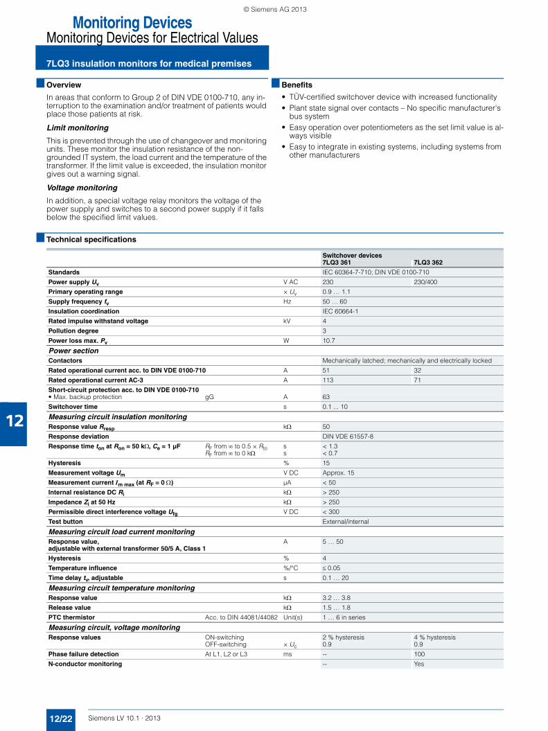
■ Overview
In areas that conform to Group 2 of DIN VDE 0100-710, any in-terruption to the examination and/or treatment of patients would place those patients at risk.
Limit monitoring
This is prevented through the use of changeover and monitoring units. These monitor the insulation resistance of the non-grounded IT system, the load current and the temperature of the transformer. If the limit value is exceeded, the insulation monitor gives out a warning signal.
Voltage monitoring
In addition, a special voltage relay monitors the voltage of the power supply and switches to a second power supply if it falls below the specified limit values.
■ Benefits
• TÜV-certified switchover device with increased functionality• Plant state signal over contacts – No specific manufacturer's
bus system• Easy operation over potentiometers as the set limit value is al-
ways visible • Easy to integrate in existing systems, including systems from
other manufacturers
■ Technical specifications
Switchover devices7LQ3 361 7LQ3 362
Standards IEC 60364-7-710; DIN VDE 0100-710
Power supply Uv V AC 230 230/400
Primary operating range × Uv 0.9 … 1.1
Supply frequency fv Hz 50 … 60
Insulation coordination IEC 60664-1
Rated impulse withstand voltage kV 4
Pollution degree 3
Power loss max. Pv W 10.7
Power sectionContactors Mechanically latched; mechanically and electrically locked
Rated operational current acc. to DIN VDE 0100-710 A 51 32
Rated operational current AC-3 A 113 71
Short-circuit protection acc. to DIN VDE 0100-710 • Max. backup protection gG A 63
Switchover time s 0.1 ... 10
Measuring circuit insulation monitoringResponse value Rresp kΩ 50
Response deviation DIN VDE 61557-8
Response time ton at Ron = 50 kΩ, Ce = 1 μF RF from ∞ to 0.5 × Rto s < 1.3RF from ∞ to 0 kΩ s < 0.7
Hysteresis % 15
Measurement voltage Um V DC Approx. 15
Measurement current Im max (at RF = 0 Ω) µA < 50
Internal resistance DC Ri kΩ > 250
Impedance Zi at 50 Hz kΩ > 250
Permissible direct interference voltage Ufg V DC < 300
Test button External/internal
Measuring circuit load current monitoringResponse value, adjustable with external transformer 50/5 A, Class 1
A 5 … 50
Hysteresis % 4
Temperature influence %/°C ≤ 0.05
Time delay tv, adjustable s 0.1 … 20
Measuring circuit temperature monitoringResponse value kΩ 3.2 … 3.8
Release value kΩ 1.5 … 1.8
PTC thermistor Acc. to DIN 44081/44082 Unit(s) 1 … 6 in series
Measuring circuit, voltage monitoringResponse values ON-switching 2 % hysteresis 4 % hysteresis
OFF-switching × Uc 0.9 0.9
Phase failure detection At L1, L2 or L3 ms -- 100
N-conductor monitoring -- Yes
LV10-1_12_EN.book Seite 22 Freitag, 15. Februar 2013 11:06 11
© Siemens AG 2013

12
Monitoring DevicesMonitoring Devices for Electrical Values
7LQ3 insulation monitors for medical premises
12/23Siemens LV 10.1 · 2013
Switchover devices7LQ3 361 7LQ3 362
ConnectionTerminals
• Load circuit Feeder terminals mm² 4 ... 16Output terminals
• Communication Status signals mm² 2.5Fault indications
Environmental conditionsPermissible ambient temperature °C -20 ... 45
Mounting position Vertical
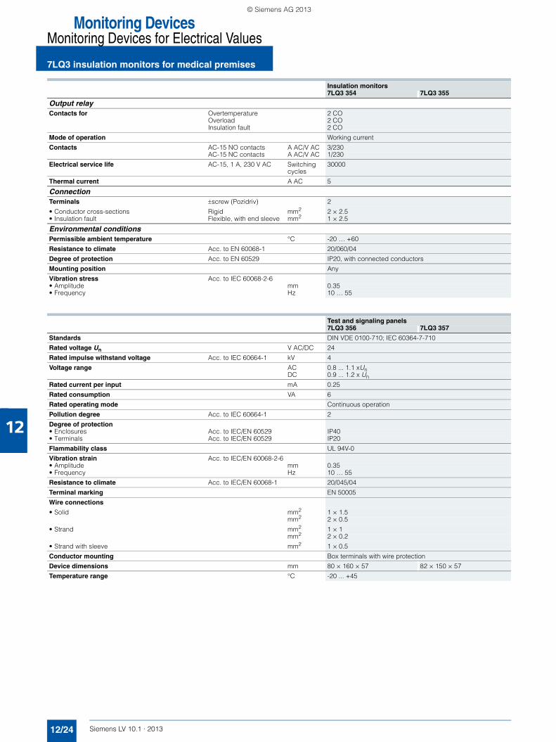
Insulation monitors7LQ3 354 7LQ3 355
Standards EN 61557-8
Power supply Uv V AC 230
Primary operating range × Uv 0.9 … 1.1
Supply frequency fv Hz 50 … 60
Power loss max. Pv VA Approx. 7
Rated system voltage Un (measuring circuit) V AC 0 … 300
Rated frequency fn Hz 10 … 1000
EMC immunity to interference IEC 61000-6-2
EMC emitted interference IEC 61000-6-3
Insulation coordination IEC 60664-1
Rated impulse withstand voltage kV 4
Pollution degree 3
Flammability class UL 94V-0
Measuring circuit insulation monitoringResponse value Rresp kΩ 50 50 ... 500
Response deviation DIN VDE 61557-8
Response time ton at Ron = 50 kΩ, Ce = 1 μF RF from ∞ to 0.5 × Ron s < 1.3RF from ∞ to 0 kΩ s < 0.7
Hysteresis % 15
Measurement voltage Um V DC Approx. 15
Measurement current Im max (at RF = 0 Ω) µA < 50
Internal resistance DC Ri kΩ > 250
Impedance Zi at 50 Hz kΩ > 250
Permissible direct interference voltage Ufg V DC < 300
Measuring circuit load current monitoringResponse value, adjustable with external transformer 50/5 A, Class 1
A 5 … 50
Hysteresis % 4
Temperature influence %/°C ≤ 0.05
Time delay tv, adjustable s 0.1 … 20
Measuring circuit temperature monitoringResponse value kΩ 3.2 … 3.8
Release value kΩ 1.5 … 1.8
PTC thermistor Acc. to DIN 44081/44082 Unit(s) 1 … 6 in series
Display and control elementsOperating error Acc. to IEC 61557-8
LED display
• Current and temperature monitoring One red and one green LED• Ready-to-run Green• Insulation fault Red• Line breakage monitoring of the isolation measuring circuit Red
• Display of current insulation resistance -- 11-step LED chain
Pushbuttons Test and Reset
LV10-1_12_EN.book Seite 23 Freitag, 15. Februar 2013 11:06 11
© Siemens AG 2013
Monitoring DevicesMonitoring Devices for Electrical Values
7LQ3 insulation monitors for medical premises
12/24 Siemens LV 10.1 · 2013
12
Insulation monitors7LQ3 354 7LQ3 355
Output relayContacts for Overtemperature 2 CO
Overload 2 COInsulation fault 2 CO
Mode of operation Working current
Contacts AC-15 NO contacts A AC/V AC 3/230 AC-15 NC contacts A AC/V AC 1/230
Electrical service life AC-15, 1 A, 230 V AC Switching cycles
30000
Thermal current A AC 5
ConnectionTerminals ±screw (Pozidriv) 2
• Conductor cross-sections Rigid mm2 2 × 2.5• Insulation fault Flexible, with end sleeve mm2 1 × 2.5
Environmental conditionsPermissible ambient temperature °C -20 … +60
Resistance to climate Acc. to EN 60068-1 20/060/04
Degree of protection Acc. to EN 60529 IP20, with connected conductors
Mounting position Any
Vibration stress Acc. to IEC 60068-2-6• Amplitude mm 0.35• Frequency Hz 10 … 55
Test and signaling panels 7LQ3 356 7LQ3 357
Standards DIN VDE 0100-710; IEC 60364-7-710
Rated voltage Un V AC/DC 24
Rated impulse withstand voltage Acc. to IEC 60664-1 kV 4
Voltage range AC 0.8 ... 1.1 xUnDC 0.9 ... 1.2 x Un
Rated current per input mA 0.25
Rated consumption VA 6
Rated operating mode Continuous operation
Pollution degree Acc. to IEC 60664-1 2
Degree of protection• Enclosures Acc. to IEC/EN 60529 IP40• Terminals Acc. to IEC/EN 60529 IP20
Flammability class UL 94V-0
Vibration strain Acc. to IEC/EN 60068-2-6• Amplitude mm 0.35• Frequency Hz 10 … 55
Resistance to climate Acc. to IEC/EN 60068-1 20/045/04
Terminal marking EN 50005
Wire connections
• Solid mm2 1 × 1.5mm2 2 × 0.5
• Strand mm2 1 × 1mm2 2 × 0.2
• Strand with sleeve mm2 1 × 0.5
Conductor mounting Box terminals with wire protection
Device dimensions mm 80 × 160 × 57 82 × 150 × 57
Temperature range °C -20 ... +45
LV10-1_12_EN.book Seite 24 Freitag, 15. Februar 2013 11:06 11
© Siemens AG 2013
12
Monitoring DevicesMonitoring Devices for Electrical Values
7LQ3 insulation monitors for medical premises
12/25Siemens LV 10.1 · 2013
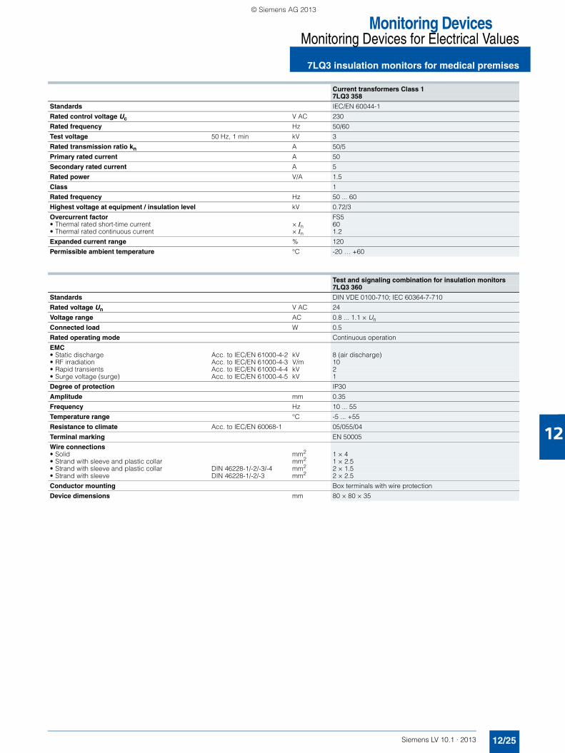
Current transformers Class 17LQ3 358
Standards IEC/EN 60044-1
Rated control voltage Uc V AC 230
Rated frequency Hz 50/60
Test voltage 50 Hz, 1 min kV 3
Rated transmission ratio kn A 50/5
Primary rated current A 50
Secondary rated current A 5
Rated power V/A 1.5
Class 1
Rated frequency Hz 50 ... 60
Highest voltage at equipment / insulation level kV 0.72/3
Overcurrent factor FS5• Thermal rated short-time current × In 60• Thermal rated continuous current × In 1.2
Expanded current range % 120
Permissible ambient temperature °C -20 … +60
Test and signaling combination for insulation monitors7LQ3 360
Standards DIN VDE 0100-710; IEC 60364-7-710
Rated voltage Un V AC 24
Voltage range AC 0.8 ... 1.1 × Un
Connected load W 0.5
Rated operating mode Continuous operation
EMC• Static discharge Acc. to IEC/EN 61000-4-2 kV 8 (air discharge)• RF irradiation Acc. to IEC/EN 61000-4-3 V/m 10• Rapid transients Acc. to IEC/EN 61000-4-4 kV 2• Surge voltage (surge) Acc. to IEC/EN 61000-4-5 kV 1
Degree of protection IP30
Amplitude mm 0.35
Frequency Hz 10 ... 55
Temperature range °C -5 ... +55
Resistance to climate Acc. to IEC/EN 60068-1 05/055/04
Terminal marking EN 50005
Wire connections• Solid mm2 1 × 4• Strand with sleeve and plastic collar mm2 1 × 2.5• Strand with sleeve and plastic collar DIN 46228-1/-2/-3/-4 mm2 2 × 1.5• Strand with sleeve DIN 46228-1/-2/-3 mm2 2 × 2.5
Conductor mounting Box terminals with wire protection
Device dimensions mm 80 × 80 × 35
LV10-1_12_EN.book Seite 25 Freitag, 15. Februar 2013 11:06 11
© Siemens AG 2013

Monitoring DevicesMonitoring Devices for Electrical Values
7LQ3 insulation monitors for medical premises
12/26 Siemens LV 10.1 · 2013
121) Tripping units must be ordered separately.
Voltage relays
5TT3 411 5TT3 412
Rated control voltage Uc V AC 230 230/400
Overload capability × Uc 1.15 1.1
Rated frequency Hz 50/60
Response values ON-switchingOFF-switching × Uc
2 % hysteresis0.9
4 % hysteresis0.9
Minimum contact load V/mA 10/100
Phase failure detection At L1, L2 or L3 ms -- 100
N-conductor monitoring -- Yes
Rated insulation voltage Ui Between coil/contact kV 4
Contacts AC-15 NO contactsAC-15 NC contacts
32
31
Electrical service life in switching cycles AC-15, 1 A, 230 V AC 5 × 10⁵
Rated impulse withstand voltage Acc. to IEC 60664-1 kV 4
Pollution degree 2
Terminals ±screw (Pozidriv) 2
Conductor cross-sections• Rigid• Flexible, with end sleeve
mm2
mm22 × 2.52 × 1.5
Permissible ambient temperature °C -20 … +60
Resistance to climate Acc. to EN 60068-1 20/060/04
IT line transformers4AT3/4AT4
In the case of isolating transformers used to set up medical IT systems, overcurrent protective devices are only permissible as protection against short circuits. To protect the isolating transformers against overload they are fitted with monitoring devices that signal an excessive rise in tempera-ture (e.g. 7LQ3 354 insulation monitors).
Standards EN 61558-2-15
Safety class I
Static shield between primary and secondary winding With insulated connection
Thermistor transformer protection Warning in the event of thermal overload1)
Insulation monitoring With center tap
Short-circuit voltage uz % ≤ 3
No-load supply current i0 % ≤ 3• Starting current (rush), max. x I1N 8
Rated ambient temperature ta /Thermal Class 55 °C/H
LV10-1_12_EN.book Seite 26 Freitag, 15. Februar 2013 11:06 11
© Siemens AG 2013

12
Monitoring DevicesMonitoring Devices for Electrical Values
7LQ3 insulation monitors for medical premises
12/27Siemens LV 10.1 · 2013* You can order this quantity or a multiple thereof.
■ Selection and ordering data
Version Ue Ie Uc Mounting width
DT Order No. Priceper PU
PU(UNIT,
SET,M)
PS*/P. unit
PG Weightper PU
approx.
V AC A V AC MW kg
Switchover devices according to VDE 0100-710 for medical premises
2-pole, for medical premises of Group 2, for switching over two redundant supply leads, monitoring of IT system and theIT line transformer, up to 8 kVA
230 51 230 7LQ3 361 1 1 unit 027 17.500
4-pole, for use with symmetric loads
230 32 230/400 7LQ3 362 1 1 unit 027 17.500
Insulation monitors
with load current and temperature monitoringfor medical premises
230 6 7LQ3 354 1 1 unit 027 0.396
with load current and temperature monitoring of medical premises with adjustable response value of 50 … 500 kΩ and output for 7LQ3 360 test and signaling combination
230 8 7LQ3 355 1 1 unit 027 0.600
Test and signaling panels
For switchover devices, 24 V AC/DC, 50/60 Hz
surface mounting 7LQ3 356 1 1 unit 027 0.325
Flush mounting 7LQ3 357 1 1 unit 027 0.220
LV10-1_12_EN.book Seite 27 Freitag, 15. Februar 2013 11:06 11
© Siemens AG 2013

Monitoring DevicesMonitoring Devices for Electrical Values
7LQ3 insulation monitors for medical premises
12/28 Siemens LV 10.1 · 2013
12
* You can order this quantity or a multiple thereof.
Version Ue Ie Uc Mounting width
DT Order No. Priceper PU
PU(UNIT,
SET,M)
PS*/P. unit
PG Weightper PU
approx.
V AC A V AC MW kg
Test and signaling combinationfor insulation monitors
24 V AC 50/60 Hz 7LQ3 360 1 1 unit 027 0.105
Current transformers 50A/5A AC Class 1
With base angle
230 7LQ3 358 1 1 unit 027 0.390
Voltage relays for undervoltage monitoring of medical premises
Single-phase against N with test button, switching thresholds: 0.9 × Un, 2 % hysteresis
2 NO + 2 NC 230 4 230 4 5TT3 411 1 1 unit 027 0.220
Single, two or three-phase against N, with asymmetry, reverse voltage and phase failure detection, with N-conductor monitoring, and one test button each for the phases, switching thresholds: 0.9 × Un, 4 % hysteresis
1 CO, 1 NO, 1 NC 230 4 230/400 4 5TT3 412 1 1 unit 027 0.230
LV10-1_12_EN.book Seite 28 Freitag, 15. Februar 2013 11:06 11
© Siemens AG 2013
12
Monitoring DevicesMonitoring Devices for Plants and Equipment
5TT3 fault signaling units
12/29Siemens LV 10.1 · 2013* You can order this quantity or a multiple thereof.
■ Overview
Fault signaling units are used in small plants where the installa-tion of complex fault signaling systems would be too labor-inten-sive and too expensive. In the event of a fault, they enable fast fault localization of all monitoring devices and limit monitors in-stalled in a plant from a central location. This increases plant availability. With the correct sensor configuration, they also pro-vide the option of preventative maintenance.• 4 fault signal inputs with LED• 1 LED as centralized fault indicator• One unit each for centralized fault indication and acoustic sig-
naling• With acknowledgment for acoustic indicators• Open-/closed-circuit principle to the 4 inputs can be adjusted
via jumpers X1 - X2• A maximum of 39 5TT3 461 expansion fault signaling units can
be connected to the 5TT3 460 centralized fault signaling unit
• The maximum possible cable length between 5TT3 460 cen-tralized fault signaling units and 5TT3 461 expansion fault sig-naling units is approx. 100 m with a conductor cross-section of 1.5 mm2
■ Benefits
• Ultra compact device designs that only require the smallest of spaces in distribution boards
• The modular design means that it is easy to add devices as your system expands
■ Technical specifications
■ Selection and ordering data
5TT3 460 5TT3 461
Standards IEC 60255; IEC 61810
Rated control voltage Uc V AC 230
Primary operating range × Uc 0.8 ... 1.1
Rated frequency fn Hz 50/60
Fault signaling inputs S1 ... S4 V AC 230
Signal voltage
to terminals S and H
V 7 ... 10
Noise pulse duration ms ≥ 100
Acknowledgment pulse duration ms ≥ 200
Contacts
• Rated operational voltage Ue V AC 230 --
• Rated operational current Ie A 5 --
• Minimum contact load V; mA 10; 100 --
Connections
• Terminals ±screw (Pozidriv) PZ 1
• Conductor cross-sections- Rigid, max. mm2 2 × 2.5- Flexible, with end sleeve, min. mm2 1 × 0.5
Permissible ambient temperature °C -20 ... +60
Humidity class Acc. to IEC 60068-2-30 F
Ue Ie Uc Mounting width
DT Order No. Priceper PU
PU(UNIT,
SET, M)
PS*/P. unit
PG Weightper PU
approx.
V AC A AC V AC MW kg
Centralized fault signaling units with transparent cap
230 5 230 2 5TT3 460 1 1 unit 026 0.149
Expansion fault signaling units with transparent cap
230 -- -- 2 5TT3 461 1 1 unit 026 0.124
LV10-1_12_EN.book Seite 29 Freitag, 15. Februar 2013 11:06 11
© Siemens AG 2013

Monitoring DevicesMonitoring Devices for Plants and Equipment
5TT5 EMERGENCY STOP modules
12/30 Siemens LV 10.1 · 2013* You can order this quantity or a multiple thereof.
12
■ Overview
EMERGENCY STOP circuits are common safety measures in all laboratory equipment and industrial plants. The EMERGENCY STOP modules used here must meet the most rigorous demands with regard to functional reliability. Benchmark is the degree of self-monitoring.
■ Benefits
• The electrical separation between electric circuit and control meets the requirements of the standard
• An LED for the operating and switching state provides con-stant information on the operating state
■ Technical specifications
■ Selection and ordering data
5TT5 200
Standards IEC 60204-1; EN 60204-1 (VDE 0113-1)
Supply
• Rated control voltage Uc V AC 230- Primary operating range × Uc 0.8 ... 1.1
• Rated frequency fn Hz 50
• Rated power dissipation Pv Coil/drive 3.5Contact per pole VA 0.8
Control voltage Terminal Y1 V AC/DC 24
Control current Terminal Y1 mA DC 45
Recovery time ms 500
Safety
• Electrical separation, creepage distances and clearances, actuator/contact mm 3
• Rated impulse withstand voltage Uimp drive/contact kV > 4
Contacts
• Contacts NO contacts AC-15 A 3NC contacts AC-15 A 2NO contact/NC contact AC-1 A 5
• Contact gap mm > 1
• Electrical service life AC-15, 2 A, 230 V AC Switching cycles
105
• Reliable switching frequency Switching cycles/h
600
Vibration resistanceAmplitude Acc. to
EN 60068-2-610Up to 55 Hz
mm 0.35
Connections
• Terminals ±screw (Pozidriv) PZ 1
• Conductor cross-sections of main current paths- Rigid Max. mm2 2 × 2.5- Flexible, with end sleeve Min. mm2 1 × 0.5
Permissible ambient temperature °C 0 ... +50
Resistance to climate Acc. to EN 60068-1 0/55/04
Ue Ie Uc Mounting width
DT Order No. Priceper PU
PU(UNIT,
SET,M)
PS*/P. unit
PG Weightper PU
approx.
V AC A AC V AC MW kg
EMERGENCY STOP modules
400 5 230 4 5TT5 200 1 1 unit 026 0.284
LV10-1_12_EN.book Seite 30 Freitag, 15. Februar 2013 11:06 11
© Siemens AG 2013

Monitoring DevicesMonitoring Devices for Plants and Equipment
5TT3 level relays
12/31Siemens LV 10.1 · 2013
12
■ Overview
Level relays are used for the monitoring and control of conduc-tive, non-combustible liquids and powders. They ensure over-flow and dry run protection. Due to their sensor performance, the devices can also be used for general resistance monitoring.
LED displays:• Green LED: lights up when operational voltage is applied• Yellow LED: lights up if MIN output relay is activated• Red LED: lights up if MAX output relay is activated
■ Benefits
The measuring range up to 450 kΩ enables a differentiation be-tween foam and liquid. It also increases the universal application for resistance measurements.
Due to its low-frequency, electrically isolated measuring circuit, the device has a high immunity to interference against system coupling, which enables cable lengths of up to 1500 m and sup-presses the effects of electrolysis in the liquid• The two outputs for minimum and maximum control can also
be used for the advance warning and tripping of limit values• 3 electrode connections for 1-step and 2-step level control• All standard products can be used as electrodes• High immunity to interference of the measuring circuit isolated
from the system• Programmable for open-circuit principle (with bridge X2 COM)
or closed-circuit principle (without jumper)• Separately adjustable delay times for tv min and tv max, 0.2 s to
2 s
■ Technical specifications
5TT3 435
Standards IEC 60255; IEC 61810
Supply
• Rated control voltage Uc V AC 230- Primary operating range × Uc 0.8 ... 1.1
• Rated frequency fn Hz 50/60
Setting range of the liquid level kΩ 2 ... 450
Switching point hysteresis of set value
• At 450 kΩ % 3• At 2 kΩ % 6
Voltage temperature influence From set value % < 2
Max. cable length to the Set value kΩElectrodes at 100 μF/km 450 m 50
100 m 20035 m 50010 m 1500
5 m 3000
Electrode voltage Max. V AC Approx. 10
Electrode current Max. mA AC Approx. 1.5
Response delay adjustable s 0.2 ... 20
OFF-delay adjustable s 0.2 ... 20
Rated operational voltage Ue V 250
Rated operational current Ie A 5
Test voltageInput/auxiliary circuit kV 4Input/output circuit kV 4Auxiliary/output circuit kV 4
Connections
• Terminals ±screw (Pozidriv) PZ 2
• Conductor cross-sections- Rigid Max. mm2 2 × 2.5- Flexible, with end sleeve Min. mm2 1 × 0.5
Permissible ambient temperature °C -20 ... +60
Resistance to climate Acc. to EN 60068-1 20/60/4
LV10-1_12_EN.book Seite 31 Freitag, 15. Februar 2013 11:06 11
© Siemens AG 2013
Monitoring DevicesMonitoring Devices for Plants and Equipment
5TT3 level relays
12/32 Siemens LV 10.1 · 2013
12
* You can order this quantity or a multiple thereof.
■ Selection and ordering data
Ue Ie Uc Mounting width
DT Order No. Priceper PU
PU(UNIT,
SET,M)
PS*/P. unit
PG Weightper PU
approx.
V AC A AC V AC MW kg
Level relays
230 4 230 2 5TT3 435 1 1 unit 027 0.188
Immersion electrodes
• Made of stainless steel, with PG13 sealing cap• Temperature range 0 ... 60 °C• Suitable for pure water in open containers
With terminal connection 5TG8 223 1 1/24 units 026 0.087
LV10-1_12_EN.book Seite 32 Freitag, 15. Februar 2013 11:06 11
© Siemens AG 2013

12
Monitoring DevicesMonitoring Devices for Plants and Equipment
5TT3 line circuit relays
12/33Siemens LV 10.1 · 2013* You can order this quantity or a multiple thereof.
■ Overview
Line circuit relays are used to interrupt circuits and prevent elec-tromagnetic fields in circuits where there are currently no active loads. If the loads are disconnected, and the line circuit relay measures a usage of only 2 to 20 VA - adjustable - it disconnects the cable to the supply voltage and switches over to extra-low voltage. As soon as loads are reconnected, the line circuit relay detects the increase in usage and switches back to the supply voltage. While the line circuit relay switches off any unnecessary system components, it is not a device for ensuring isolation in the sense of safe disconnection.
The line circuit relay is unable to detect consumers with elec-tronic power supply units, e.g. electronically controlled vacuum cleaners. It is expedient to connect such devices to a base load resistor (PTC resistor) so that the line circuit relay is reset to sup-ply voltage.
■ Benefits
• High availability to a wide range of loads, as all resistive, ca-pacitive and inductive loads are detected
• Adjustable from 2 VA to 20 VA• With status display for contact adjustment• With switch continuously ON• With safety information on stickers for socket outlets and dis-
tribution boards
■ Technical specifications
■ Selection and ordering data
5TT3 171
Standards IEC 60255; IEC 61810
Rated control voltage Uc V AC 230
Primary operating range × Uc 0.85 ... 1.15
Rated frequency Hz 50/60
Rated power dissipation Pv Electronics VA 5Contacts VA 2.6
Monitoring voltage V 3
Response value adjustable VA 2 ... 20
Release value % of the response value 70
Rated impulse withstand voltage Uimp Input/output kV > 4
Rated operational voltage Ue V AC 250
Rated operational current Ie AC-1 A 16AC-11 A 3
Contacts μ contact
Electrical service life in switching cycles at 3 A -11 AC 5 × 10⁵
Terminals +/-screw (Pozidriv) PZ 1
Conductor cross-sections
• Rigid Max. mm2 2 × 2.5• Flexible, with end sleeve Min. mm2 1 × 0.5
Permissible ambient temperature °C -20 ... +45
Degree of protection Acc. to IEC/EN 60529 IP20, with connected conductors
Safety class Acc. to EN 61140/VDE 0140-1 II
Humidity class Acc. to IEC 60068-2-30 F
Contacts Ue Ie Uc Mounting width
DT Order No. Priceper PU
PU(UNIT,
SET,M)
PS*/P. unit
PG Weightper PU
approx.
V AC A AC V AC MW kg
Line circuit relays
For disconnecting the voltage of electrical systems even when loads are disabled
1 NC 250 16 230 1 5TT3 171 1 1 unit 027 0.087
Base load resistors for electronic devices
With 15-cm connection wires, end sleeves and shrink sleeving
5TG8 222 1 1 unit 026 0.006
LV10-1_12_EN.book Seite 33 Freitag, 15. Februar 2013 11:06 11
© Siemens AG 2013

Monitoring DevicesMonitoring Devices for Plants and Equipment
12/34 Siemens LV 10.1 · 2013* You can order this quantity or a multiple thereof.
12
■ Overview
The p.f. monitors monitor the phase displacement between cur-rent and voltage. Because the phase displacement angle changes with the load of the motor, this measurement method is ideal for the monitoring of asynchronous motors for underload and no-load operation, independent of size. However, in some cases, the p.f. barely changes if the load of the motor changes, e.g. in the case of relatively minor load changes on large-scale motors or single-phase split-pole motors or collector motors.
The p.f. monitor monitors single and three-phase asynchronous motors up to approx. 5 A (without current transformer) for under-load and no-load operation. This is phase-sequence-indepen-dent and increases plant availability. Typical applications are fan monitoring in the case of V-belt breakage, pump monitoring in
the event of valve closure or dry runs. A current transformer is used for higher rated currents.
If the lower p.f. value set at the p.f. monitor is violated for the du-ration of the set response delay, the output relay switches to the alarm state and the red LED lights up. If the higher p.f. value is violated, the output relay switches back without any significant delay.• Adjustable p.f. response value, from 0 to 0.97• Current range up to 8 A• LED display for operation and alarm• Automatic resetting of alarm
■ Benefits
• The ultra compact p.f.monitor requires only the smallest of spaces and saves costs
■ Technical specifications
■ Selection and ordering data
5TT3 472
Standards IEC/EN 60255, VDE 0435
Rated control voltage Uc 3 V AC 400
Primary operating range With AC supply × Uc 0.8 ... 1.1
Frequency range fn Hz 45 ... 65
Rated power dissipation Pv VA Approx. 11
Rated impulse withstand voltage Uimp Against contacts kV < 4
Current measuring circuits For AC systems
Current measuring range Imeas A AC 0.4 ... 8
Short-time load carrying capacity For 2 s A 20For 0.5 s A 40
Current transformer, Class 3 or better Secondary current A 1 or 5
Setting range adjustable p.f. 0 ... 0.97
Response delay adjustable s 1 ... 100
Short-circuit withstand current fuse 4 A gL A 4
Contacts μ contact 1 CO
• Rated operational voltage Ue V AC 250
• Rated operational current Ie Thermal current A 4AC-15 NO contacts A 3AC-15 NC contacts A 1AC-13 at 24 V DC A 1
• Minimum contact load V; mA 10; 100
Connections
• Terminals ±screw (Pozidriv) PZ 2
• Conductor cross-sections- Rigid Max. mm2 2 × 2.5- Flexible, with end sleeve Min. mm2 1 × 0.5
Permissible ambient temperature °C -20 ... +60
Resistance to climate Acc. to EN 60068-1 20/60/4
Degree of protection Acc. to EN 60529 IP20, with connected conductors
Contacts Ue Ie Uc Mounting width
DT Order No. Priceper PU
PU(UNIT,
SET,M)
PS*/P. unit
PG Weightper PU
approx.
V AC A AC V AC MW kg
p.f. monitors
For monitoring of the underload of motors up to approx. 5 A AC by making p.f. mea-surements, setting range p.f. from 0 ... 0.97
1 CO 4 3 × 400 0.4 ... 8 1 5TT3 472 1 1 unit 026 0.081
5TT3 p.f. monitors
LV10-1_12_EN.book Seite 34 Freitag, 15. Februar 2013 11:06 11
© Siemens AG 2013
12
Monitoring DevicesMonitoring Devices for Plants and Equipment
5TT3 motor protection relays
12/35Siemens LV 10.1 · 2013* You can order this quantity or a multiple thereof.
■ Overview
Thermistor motor protection relays monitor the thermistors wound in motors. This helps to prevent thermal motor overloads, e.g. due to high switching frequency, single-phasing, disabled cooling or excessive ambient temperatures. Up to 6 thermistors in series can be monitored. A conductor break in the sensor con-ductor will immediately trip the device. The device can also be used for monitoring wound quick-break switches - e.g. bimetal thermostats. This offers all-round motor protection.• For the detection of
- Violation of upper temperature limits- Wire breaks in sensor circuits
• 1 input for 1 to 6 thermistors• With 2 LEDs green/red for ready-to-run and fault
• Response value: 3.2 to 3.8 kΩ• Release value: 1.5 to 1.8 kΩ• Max. cable length of sensor supply cable NYM 2 × 1.5
is 100 m• Remote Reset: over A1/A2 (NC contact) or over X1/X2
(NO contact)
LED displays:• Green LED: lights up when operational voltage is applied• Red LED: lights up in the event of overtemperatures or an in-
terruption in the sensor circuit
■ Benefits
• The test button for the diagnosis of the devices ensures high functional reliability for users
• The ultra compact thermistor motor protection relay requires only the smallest of spaces. This saves costs
• A remote reset enables the device to be switched back on again centrally at any time. This increases system availability
■ Technical specifications
■ Selection and ordering data
5TT3 4315TT3 432
Standards IEC 60255; IEC 61810
Rated control voltage Uc V AC 230
Primary operating range ×Uc 0.9 ... 1.1
Rated frequency Hz 50/60
Response value kΩ 3.2 ... 3.8
Release value kΩ 1.5 ... 1.8
Minimum contact load V; mA 10; 100
Rated insulation voltage Ui Between coil/contact kV 4
Rated impulse withstand voltage Uimp Actuator/contact kV > 2.5
Contacts μ contact (AC-11) A 3
• Rated operational voltage Ue V AC 230
• Rated operational current Ie A 5Actuator/contact mm 4
Connections
• Terminals ±screw (Pozidriv) PZ 1
• Conductor cross-sections- Rigid Max. mm2 2 x 2.5- Flexible, with end sleeve Min. mm2 1 x 0.5
Permissible ambient temperature °C -20 ... +60
Resistance to climate Acc. to EN 60068-1 20/60/4
Ue Ie Uc Mounting width
DT Order No. Priceper PU
PU(UNIT,
SET,M)
PS*/P. unit
PG Weightper PU
approx.
V AC A AC V AC MW kg
Thermistor motor protection relays
230 5 230 2 5TT3 431 1 1 unit 027 0.167
With fault storage, reset pushbutton and remote reset
230 5 230 2 5TT3 432 1 1 unit 027 0.172
LV10-1_12_EN.book Seite 35 Freitag, 15. Februar 2013 11:06 11
© Siemens AG 2013
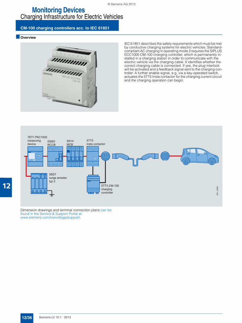
Monitoring DevicesCharging Infrastructure for Electric Vehicles
CM-100 charging controllers acc. to IEC 61851
12/36 Siemens LV 10.1 · 2013
12
■ Overview
IEC 61851 describes the safety requirements which must be met by conductive charging systems for electric vehicles. Standard-compliant AC charging in operating mode 3 requires the SIPLUS ECC1000 CM-100 charging controller, which is permanently in-stalled in a charging station in order to communicate with the electric vehicle via the charging cable. It identifies whether the correct charging cable is connected. If yes, the plug interlock will be activated and a feedback signal sent to the charging con-troller. A further enable signal, e.g. via a key-operated switch, actuates the 5TT5 Insta contactor for the charging current circuit and the charging operation can begin.
Dimension drawings and terminal connection plans can be found in the Service & Support Portal at:www.siemens.com/lowvoltage/support.
7KT1 PAC1500measuring device
5TT5insta contactor
5SD7surge arrestertyp 2
5TT3 CM-100charging controller
5SM3RCCB
5SY4MCB
I201
_183
55
LV10-1_12_EN.book Seite 36 Freitag, 15. Februar 2013 11:06 11
© Siemens AG 2013

12
Monitoring DevicesCharging Infrastructure for Electric Vehicles
CM-100 charging controllers acc. to IEC 61851
12/37Siemens LV 10.1 · 2013* You can order this quantity or a multiple thereof.
■ Technical specifications
■ Selection and ordering data
Charging controllers 5TT3 200-1KK20 5TT3 200-2KK20 5TT3 200-3KK20 5TT3 200-4KK20 5TT3 200-6KK20 5TT3 200-2KK30
Standard Acc. to IEC/EN 61851 Mode 3
Vehicle communication• Charging mode 3 acc. to IEC 61851-1• Number of
charging interfaces1
Operational voltage V AC 110 ... 230 110 ... 230 110 ... 230 --V DC -- -- -- 18 ... 28
Rated frequency Hz 50/60
Rated charging current A 13 16 20 32 13/32, switchable
16
Maximum power loss W 6
Surge strength kV 4
Degree of protection IP20
Pollution degree 3 acc. to IEC/EN 61010-1
Overvoltage category II
Ambient operating tempera-ture
°C -25 ... +60
Storage temperature °C -25 ... +70
Relative humidity % ≤ 95
Terminals Removable screw terminals
Conductor cross-sections• Rigid mm2 0.5 … 2.5• Flexible, with end sleeve mm2 0.5 … 2.5
Relay outputs• Number NO contacts 4 • Maximum contact load A 0.75 at 110/230 V AC
A 1 at 24 V DC• Electrical service life Switching
cycles80,000 at 1 A, inductive load
Digital inputs• Number 2• Input voltage V 0 ... 5
Display 1 status LED
Mounting / mounting position Vertical, on horizontal mounting rail
Operational voltage Rated charging current DT Order No. Priceper PU
PU(UNIT,
SET,M)
PS*/P. unit
PG Weightper PU
approx.
V AC V DC A kg
SIPLUS ECC1000 CM-100 charging controller
110 ... 230 -- 13 5TT3 200-1KK20 1 1 unit 050 0.249
110 ... 230 -- 16 5TT3 200-2KK20 1 1 unit 050 0.249
110 ... 230 -- 20 5TT3 200-3KK20 1 1 unit 050 0.249
110 ... 230 -- 32 5TT3 200-4KK20 1 1 unit 050 0.249
110 ... 230 -- 13/32, switchable 5TT3 200-6KK20 1 1 unit 050 0.249
-- 18 ... 28 16 5TT3 200-2KK30 1 1 unit 050 0.223
LV10-1_12_EN.book Seite 37 Freitag, 15. Februar 2013 11:06 11
© Siemens AG 2013
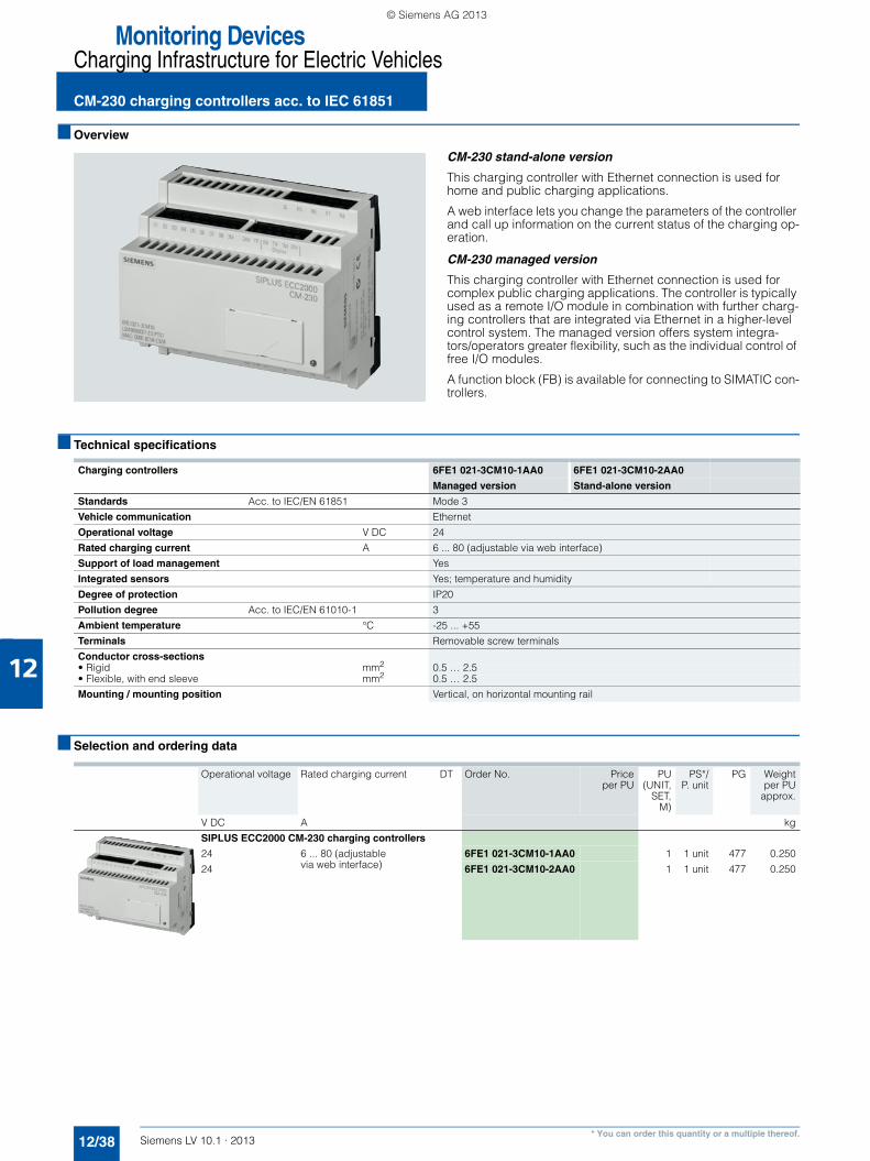
Monitoring DevicesCharging Infrastructure for Electric Vehicles
CM-230 charging controllers acc. to IEC 61851
12/38 Siemens LV 10.1 · 2013
12
* You can order this quantity or a multiple thereof.
■ Overview
CM-230 stand-alone version
This charging controller with Ethernet connection is used for home and public charging applications.
A web interface lets you change the parameters of the controller and call up information on the current status of the charging op-eration.
CM-230 managed version
This charging controller with Ethernet connection is used for complex public charging applications. The controller is typically used as a remote I/O module in combination with further charg-ing controllers that are integrated via Ethernet in a higher-level control system. The managed version offers system integra-tors/operators greater flexibility, such as the individual control of free I/O modules.
A function block (FB) is available for connecting to SIMATIC con-trollers.
■ Technical specifications
■ Selection and ordering data
Charging controllers 6FE1 021-3CM10-1AA0 6FE1 021-3CM10-2AA0
Managed version Stand-alone version
Standards Acc. to IEC/EN 61851 Mode 3
Vehicle communication Ethernet
Operational voltage V DC 24
Rated charging current A 6 ... 80 (adjustable via web interface)
Support of load management Yes
Integrated sensors Yes; temperature and humidity
Degree of protection IP20
Pollution degree Acc. to IEC/EN 61010-1 3
Ambient temperature °C -25 ... +55
Terminals Removable screw terminals
Conductor cross-sections• Rigid mm2 0.5 … 2.5• Flexible, with end sleeve mm2 0.5 … 2.5
Mounting / mounting position Vertical, on horizontal mounting rail
Operational voltage Rated charging current DT Order No. Priceper PU
PU(UNIT,
SET,M)
PS*/P. unit
PG Weightper PU
approx.
V DC A kg
SIPLUS ECC2000 CM-230 charging controllers
24 6 ... 80 (adjustable via web interface)
6FE1 021-3CM10-1AA0 1 1 unit 477 0.250
24 6FE1 021-3CM10-2AA0 1 1 unit 477 0.250
LV10-1_12_EN.book Seite 38 Freitag, 15. Februar 2013 11:06 11
© Siemens AG 2013
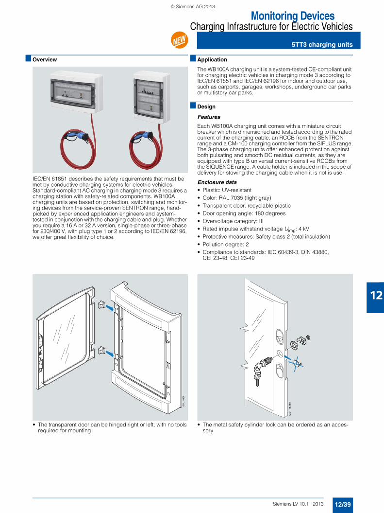
Monitoring DevicesCharging Infrastructure for Electric Vehicles
5TT3 charging units
12/39Siemens LV 10.1 · 2013
12
■ Overview
IEC/EN 61851 describes the safety requirements that must be met by conductive charging systems for electric vehicles. Standard-compliant AC charging in charging mode 3 requires a charging station with safety-related components. WB100A charging units are based on protection, switching and monitor-ing devices from the service-proven SENTRON range, hand-picked by experienced application engineers and system-tested in conjunction with the charging cable and plug. Whether you require a 16 A or 32 A version, single-phase or three-phase for 230/400 V, with plug type 1 or 2 according to IEC/EN 62196, we offer great flexibility of choice.
■ Application
The WB100A charging unit is a system-tested CE-compliant unit for charging electric vehicles in charging mode 3 according to IEC/EN 61851 and IEC/EN 62196 for indoor and outdoor use, such as carports, garages, workshops, underground car parks or multistory car parks.
■ Design
Features
Each WB100A charging unit comes with a miniature circuit breaker which is dimensioned and tested according to the rated current of the charging cable, an RCCB from the SENTRON range and a CM-100 charging controller from the SIPLUS range.The 3-phase charging units offer enhanced protection against both pulsating and smooth DC residual currents, as they are equipped with type B universal current-sensitive RCCBs from the SIQUENCE range. A cable holder is included in the scope of delivery for stowing the charging cable when it is not is use.
Enclosure data• Plastic: UV-resistant• Color: RAL 7035 (light gray)• Transparent door: recyclable plastic• Door opening angle: 180 degrees• Overvoltage category: III• Rated impulse withstand voltage Uimp: 4 kV• Protective measures: Safety class 2 (total insulation)• Pollution degree: 2• Compliance to standards: IEC 60439-3, DIN 43880,
CEI 23-48, CEI 23-49
• The transparent door can be hinged right or left, with no tools required for mounting
• The metal safety cylinder lock can be ordered as an acces-sory
I201
_183
59
I201
_183
60
N
LV10-1_12_EN.book Seite 39 Freitag, 15. Februar 2013 11:06 11
© Siemens AG 2013

Monitoring DevicesCharging Infrastructure for Electric Vehicles
5TT3 charging units
12/40 Siemens LV 10.1 · 2013
12
■ Technical specifications
WB100A charging unitwith charging cable and plug
5TT3 201-1KK11 5TT3 201-1KK12 5TT3 201-1KK13 5TT3 201-1KK31 5TT3 201-1KK32 5TT3 201-1KK33
Standards IEC/EN 61851-1; IEC/EN 61851-22; IEC/EN 62196-1; IEC 62196-2; IEC 60439-3; DIN 43880
Operational voltage V AC 230 230/400 230 230/400
Rated frequency Hz 50/60
Rated current A 16 32
Degree of protection IP54
Safety class II
Touch protection according to EN 50274 Finger and back-of-hand safe
Ambient conditions
• Ambient temperature °C -25 ... +40
• Storage temperature °C -25 ... +70
• Relative humidity % ≤ 95
• Installation location Suitable for interior and exterior use
Mains connection Bottom
Conductor cross-sections mm2 0.14 ... 6 0.2 ... 10 0.5 ... 16
Enclosures
• Material Plastic
• Color RAL 7035 (light gray)
• Dimensions (H x W x D) mm 285 x 410 x 140 420 x 298 x 140 285 x 410 x 140 420 x 298 x 140
• Weight kg 4.3 6 7.3
• Door Transparent door, plastic
• Lock Mechanical interlocking in the frame
Charging outlet
• Charging mode according to IEC 61851-1 3
• Connection type according to IEC 62192
C, charging cable with plug type 1
C, charging cable with plug type 2 C, charging cable with plug type 1
C, charging cable with plug type 2
Charging outlet contactor
• Rated operating current A 24 40
• Number of poles 4 NO
Residual current protective device
• RCCBs RCBO, type A super resistant
Type B, super resistant
Type A, super resistant
Type B, super resistant
• Version 1P+N 3P+N 1P+N 3P+N
• Rated current A 20 25 40
• Rated residual current mA 30
Conductor protection
• Miniature circuit breaker RCBO 1P+N 3P+N 1P+N 3P+N
• Tripping characteristic C
• Rated current A 20 32
• Rated breaking capacity kA 10
Displays Indicator light, red, yellow, green
N
LV10-1_12_EN.book Seite 40 Freitag, 15. Februar 2013 11:06 11
© Siemens AG 2013
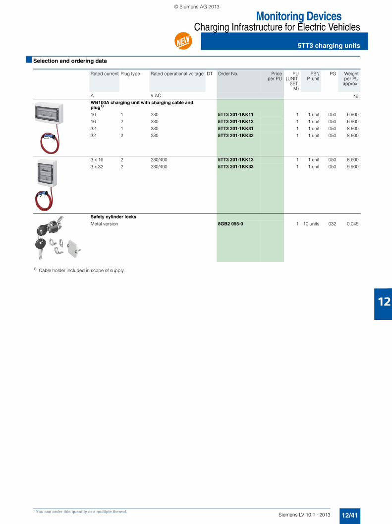
12
Monitoring DevicesCharging Infrastructure for Electric Vehicles
5TT3 charging units
12/41Siemens LV 10.1 · 2013* You can order this quantity or a multiple thereof.
■ Selection and ordering data
1) Cable holder included in scope of supply.
Rated current Plug type Rated operational voltage DT Order No. Priceper PU
PU(UNIT,
SET,M)
PS*/P. unit
PG Weightper PU
approx.
A V AC kg
WB100A charging unit with charging cable and plug1)
16 1 230 5TT3 201-1KK11 1 1 unit 050 6.900
16 2 230 5TT3 201-1KK12 1 1 unit 050 6.900
32 1 230 5TT3 201-1KK31 1 1 unit 050 8.600
32 2 230 5TT3 201-1KK32 1 1 unit 050 8.600
3 x 16 2 230/400 5TT3 201-1KK13 1 1 unit 050 8.600
3 x 32 2 230/400 5TT3 201-1KK33 1 1 unit 050 9.900
Safety cylinder locks
Metal version 8GB2 055-0 1 10 units 032 0.045
N
LV10-1_12_EN.book Seite 41 Freitag, 15. Februar 2013 11:06 11
© Siemens AG 2013
Monitoring Devices
Notes
12/42 Siemens LV 10.1 · 2013
12
LV10-1_12_EN.book Seite 42 Freitag, 15. Februar 2013 11:06 11
© Siemens AG 2013