Catalog ABB DC Drives DCS800, 20 A a 5200 A - AAINY DC Drives DCS800, 20 A a 5200 A Catalog. ... ABB...
28
ABB DC Drives DCS800, 20 A a 5200 A Catalog
Transcript of Catalog ABB DC Drives DCS800, 20 A a 5200 A - AAINY DC Drives DCS800, 20 A a 5200 A Catalog. ... ABB...

ABB DC DrivesDCS800, 20 A a 5200 A
Catalog

DCS800 - S01 - 0680 - 04 - + B055 Type code:
DC Drives
Product familyS800 = DCS800 converter
TypeS0 = 3-phase converter moduleR0 = Rebuild kitA0 = Enclosed converterE0 = Panel mounted converter
Bridge type1 = single (2-Q)2 = anti-parallel (4-Q)
Rated DC current0680 = e.g. 680 A DC (IP00)
Rated AC voltage04 = 230...400 VAC
05 = 230...525 VAC
06 = 270...600 VAC
07 = 315...690 VAC
08 = 360...800 VAC
10 = 450...990 VAC
12 = 540...1200 VAC
Power connection (D7)- = no option (sizes D1...D6)R = on the rightL = on the left
Plug-in options
External options
Type code
2 3ADW000192R0601 | DCS800 Technical catalog e f

ContentsABB DC drive DCS800
Page
ABB DC drive DCS800 ..............................................................................................................................4
DCS800 power converter modules ............................................................................................... 5Ratings, types and voltages ......................................................................................................... 6Current ratings .............................................................................................................................. 7Environmental conditions ............................................................................................................. 8Dimensioning .............................................................................................................................. 11Easy commissioning ................................................................................................................... 12Start-up assistant ....................................................................................................................... 13DCS800 firmware ........................................................................................................................ 14
Plug-in options ........................................................................................................................................15
External field supply ................................................................................................................................16Fuse connections ....................................................................................................................................18Line reactors ............................................................................................................................................19IEC 61131 programming .........................................................................................................................20Fieldbus control .......................................................................................................................................21DriveWindow Light 2 ...............................................................................................................................22Start-up, maintanance and integration (DriveWindow 2) ......................................................................24Start-up, maintanance and integration (DriveOPC) ...............................................................................25Remote monitoring tool ..........................................................................................................................26Service products .....................................................................................................................................27
DCS800 Technical catalog e f | 3ADW000192R0601 3
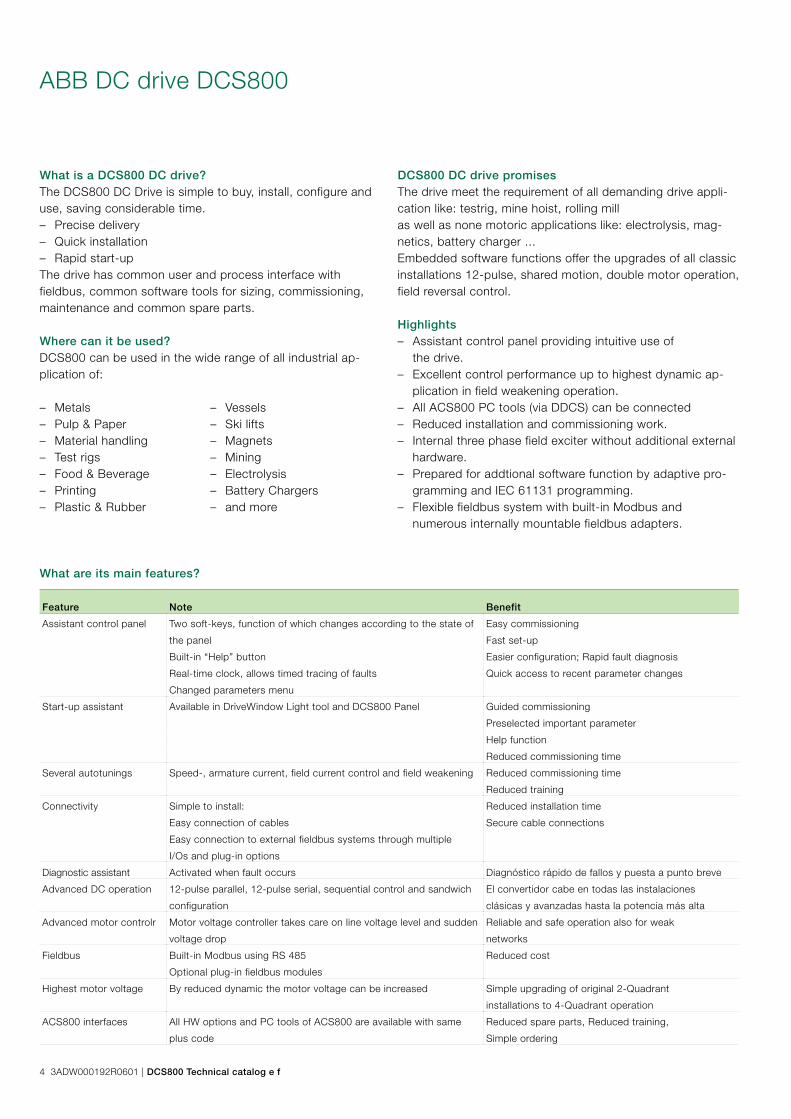
ABB DC drive DCS800
What is a DCS800 DC drive?The DCS800 DC Drive is simple to buy, install, configure and use, saving considerable time. – Precise delivery – Quick installation – Rapid start-up
The drive has common user and process interface with fieldbus, common software tools for sizing, commissioning, maintenance and common spare parts.
Where can it be used?DCS800 can be used in the wide range of all industrial ap-plication of:
What are its main features?
DCS800 DC drive promisesThe drive meet the requirement of all demanding drive appli-cation like: testrig, mine hoist, rolling mill as well as none motoric applications like: electrolysis, mag-netics, battery charger ... Embedded software functions offer the upgrades of all classic installations 12-pulse, shared motion, double motor operation, field reversal control.
Highlights – Assistant control panel providing intuitive use of
the drive. – Excellent control performance up to highest dynamic ap-
plication in field weakening operation. – All ACS800 PC tools (via DDCS) can be connected – Reduced installation and commissioning work. – Internal three phase field exciter without additional external
hardware. – Prepared for addtional software function by adaptive pro-
gramming and IEC 61131 programming. – Flexible fieldbus system with built-in Modbus and
numerous internally mountable fieldbus adapters.
– Metals – Pulp & Paper – Material handling – Test rigs – Food & Beverage – Printing – Plastic & Rubber
– Vessels – Ski lifts – Magnets – Mining – Electrolysis – Battery Chargers – and more
Feature Note Benefit
Assistant control panel Two soft-keys, function of which changes according to the state of
the panel
Built-in “Help” button
Real-time clock, allows timed tracing of faults
Changed parameters menu
Easy commissioning
Fast set-up
Easier configuration; Rapid fault diagnosis
Quick access to recent parameter changes
Start-up assistant Available in DriveWindow Light tool and DCS800 Panel Guided commissioning
Preselected important parameter
Help function
Reduced commissioning time
Several autotunings Speed-, armature current, field current control and field weakening Reduced commissioning time
Reduced training
Connectivity Simple to install:
Easy connection of cables
Easy connection to external fieldbus systems through multiple
I/Os and plug-in options
Reduced installation time
Secure cable connections
Diagnostic assistant Activated when fault occurs Diagnóstico rápido de fallos y puesta a punto breve
Advanced DC operation 12-pulse parallel, 12-pulse serial, sequential control and sandwich
configuration
El convertidor cabe en todas las instalaciones
clásicas y avanzadas hasta la potencia más alta
Advanced motor controlr Motor voltage controller takes care on line voltage level and sudden
voltage drop
Reliable and safe operation also for weak
networks
Fieldbus Built-in Modbus using RS 485
Optional plug-in fieldbus modules
Reduced cost
Highest motor voltage By reduced dynamic the motor voltage can be increased Simple upgrading of original 2-Quadrant
installations to 4-Quadrant operation
ACS800 interfaces All HW options and PC tools of ACS800 are available with same
plus code
Reduced spare parts, Reduced training,
Simple ordering
4 3ADW000192R0601 | DCS800 Technical catalog e f

DCS800 power converter modules
GeneralThe power converter modules DCS800-S have the protection class IP00 and are to be mounted in a cubicle or finger pro-tected area. There are different sizes (D1, D2, D3, D4, D5, D6, D7), graduated in terms of current and voltage ranges.
All units are equipped with the DCS800 Control Panel. It can be snapped into place on the power converter module or installed in the switchgear cubicle door by means of a mount-ing kit.
Accessories such as external fuses, line reactors etc. are also available, to complete the drive system.
All converter modules up to 525 V and 1000 A (D1...D4) are equipped with field exciters.The power section of the converters is available as single (2-Q) bridge or double (4-Q) bridge. 4-Q drives are required for regenerative breaking. 4-Q drives can be built by:
– Double (4-Q) armature bridge or – Single (2-Q) armature bridge plus a double (4-Q) field con-
verter bridge
The bridge type has an influence on the maximum output volt-age of the converter. See table below.
Reference variablesThe voltage characteristics are shown in the table beside. The DC voltage characteristics have been calculated using the fol-lowing assumptions:
– UVN = rated input terminal voltage, 3-phase – Voltage tolerance ±10 % – Internal voltage drop approx. 1% – If a deviation or a voltage drop has to be taken into con-
sideration in compliance with IEC and VDE standards, the output voltage or the output current must be reduced by the actual factor according to the table on the right.
If armature voltages higher than recommended are requested, please check carefully, whether your system is still working under safe conditions. The maximum output voltage of a 4-Q drive can be increased up to the level of Udmax 2-Q. Thus the torque reversal from motoring mode to generating mode increases up to 300 ms. This lowers the dynamics of the drive and is only recommend-ed for non-dynamic applications (e.g. E-Stop function).
System
connection
voltage
DC voltage
(recommended)
Ideal DC
voltage without
load
Recommended
DCS800
voltage class UVN [V] Udmax 2-Q [V] Udmax 4-Q [V] Udi0 [V]
230 265 240 310 04
380 440 395 510 04
400 465 415 540 04
415 480 430 560 04
440 510 455 590 05
460 530 480 620 05
480 555 500 640 05
500 580 520 670 05
525 610 545 700 06
575 670 600 770 06
600 700 625 810 06
660 765 685 890 07
690 800 720 930 07
800 915 820 1060 08
990 1160 1040 1350 10
1200 1380 1235 1590 12
Tensão do Motor
Corrente
max. tensão regenerativa do motor
2-Q
4-Q
Velocidade
Torque
2-Q
4-Q
DCS800 Technical catalog e f | 3ADW000192R0601 5
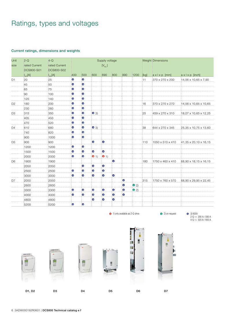
Unit 2-Q 4-Q Supply voltage Weight Dimensions
size rated Current rated Current [VAC ]
DCS800-S01 DCS800-S02
IDC[A] IDC[A] 400 500 600 690 800 990 1200 [kg] a x l x p [mm] a x l x p [inch]
D1 20 25 11 370 x 270 x 200 14,56 x 10,65 x 7,90
45 50
65 75
90 100
125 140
D2 180 200 16 370 x 270 x 270 14,56 x 10,65 x 10,65
230 260
D3 315 350 3) 25 459 x 270 x 310 18,07 x 10,65 x 12,25
405 450
470 520
D4 610 680 3) 38 644 x 270 x 345 25,35 x 10,75 x 13,60
740 820
900 1000
D5 900 900 110 1050 x 510 x 410 41,35 x 20,10 x 16,15
1200 1200
1500 1500
2000 2000 1) 1)
D6 1900 1900 180 1750 x 460 x 410 68,90 x 18,15 x 16,15
2050 2050
2500 2500
3000 3000
D7 2050 2050 315 1750 x 760 x 570 68,90 x 29,95 x 22,45
2600 2600 2)
3300 3300 2)
4000 4000
4800 4800
5200 5200
1) only available as 2-Q drive 2) on request
Current ratings, dimensions and weights
Ratings, types and voltages
3) 600V2-Q -> 290 A / 590 A4-Q -> 320 A / 650 A
D1, D2 D3 D4 D5 D6 D7
6 3ADW000192R0601 | DCS800 Technical catalog e f

The current ratings for the DCS800 with 50 Hz and 60 Hz supplies are given below. The symbols are described below the table. The characteristics are based on an ambient temperature of max. 40°C and an elevation of max. 1000 m a.s.l.
Current ratings
➀ with plus code 115 V selectable
➁ with plus code 400-500 V selectable
➂ FEX425 internal field exciter as option; three-phase or single phase, separate supply max. 500 VAC
➃ ratings for rated input voltage -10%
➄ SDCS-DSL-4 board as standard IAC input = IDC out * 0.82
Unit type 2-Q converters
IDC I Pout ➃
Unit type 4-Q converters
IDC I Pout ➃
int. fi
eld
curre
nt
Fan
volt.
Air v
olum
e
P Loss
Fram
e siz
e
[A] [kW] [kW] [A] [kW] [kW] [A] [VAC] [m³/h] [kW] ➄400 V / 500 V / 525 V 400V 500V 400V 500VDCS800-S01-0020-04/05 20 9 12 DCS800-S02-0025-04/05 25 10 13 6 without fan 300 0,11 D1DCS800-S01-0045-04/05 45 21 26 DCS800-S02-0050-04/05 50 21 26 6
115/230; 1-ph
300 0,17 D1DCS800-S01-0065-04/05 65 30 38 DCS800-S02-0075-04/05 75 31 39 6 300 0,22 D1DCS800-S01-0090-04/05 90 42 52 DCS800-S02-0100-04/05 100 42 52 6 300 0,28 D1DCS800-S01-0125-04/05 125 58 73 DCS800-S02-0140-04/05 140 58 73 6 300 0,38 D1DCS800-S01-0180-04/05 180 84 104 DCS800-S02-0200-04/05 200 83 104 15 300 0,56 D2DCS800-S01-0230-04/05 230 107 133 DCS800-S02-0260-04/05 260 108 135 15 300 0,73 D2DCS800-S01-0315-04/05 315 146 183 DCS800-S02-0350-04/05 350 145 182 20 600 0,91 D3DCS800-S01-0405-04/05 405 188 235 DCS800-S02-0450-04/05 450 187 234 20 600 1,12 D3DCS800-S01-0470-04/05 470 213 280 DCS800-S02-0520-04/05 520 218 276 20 600 1,32 D3DCS800-S01-0610-04/05 610 284 354 DCS800-S02-0680-04/05 680 282 354 25
230; 1-ph ➀ 950 1,76 D4
DCS800-S01-0740-04/05 740 344 429 DCS800-S02-0820-04/05 820 340 426 25 950 2,14 D4DCS800-S01-0900-04/05 900 049 522 DCS800-S02-1000-04/05 1000 415 520 25 1900 2,68 D4DCS800-S01-1200-04/05 1200 558 696 DCS800-S02-1200-04/05 1200 498 624 25 ➂
230; 1-ph800 5,10 D5
DCS800-S01-1500-04/05 1500 698 870 DCS800-S02-1500-04/05 1500 623 780 25 ➂ 800 5,30 D5DCS800-S01-2000-04/05 2000 930 1160 DCS800-S02-2000-04/05 2000 830 1040 25 ➂ 800 6,60 D5DCS800-S01-2050-05 2050 953 1189 DCS800-S02-2050-05 2050 851 1066 -
400-500; 3-ph 1600 8,00 D6
DCS800-S01-2500-04/05 2500 1163 1450 DCS800-S02-2500-04/05 2500 1038 1300 - 1600 9,00 D6DCS800-S01-3000-04/05 3000 1395 1740 DCS800-S02-3000-04/05 3000 1245 1560 - 1600 11,10 D6DCS800-S01-3300-04/05 3300 1535 1914 DCS800-S02-3300-04/05 3300 1370 1716 -
400/690; 3-ph4200 11,70 D7
DCS800-S01-4000-04/05 4000 1860 2320 DCS800-S02-4000-04/05 4000 1660 2080 - 4200 13,00 D7DCS800-S01-5200-04/05 5200 2418 3016 DCS800-S02-5200-04/05 5200 2158 2704 - 4200 19,00 D7600 V / 690 V 600V 690V 600V 690VDCS800-S01-0290-06 290 203 DCS800-S02-0320-06 320 200 - 115/230; 1-ph 600 0,91 D3DCS800-S01-0590-06 590 413 DCS800-S02-0650-06 650 405 - 230; 1-ph 950 1,86 D4DCS800-S01-0900-06/07 900 630 720 DCS800-S02-0900-06/07 900 563 648 25 ➂
230; 1-ph800 5,10 D5
DCS800-S01-1500-06/07 1500 1050 1200 DCS800-S02-1500-06/07 1500 938 1080 25 ➂ 800 6,30 D5DCS800-S01-2000-06/07 2000 1400 1600 25 ➂ 800 8,10 D5DCS800-S01-2050-06/07 2050 1435 1640 DCS800-S02-2050-06/07 2050 1281 1476 -
525-690; 3-ph ➁1600 9,20 D6
DCS800-S01-2500-06/07 2500 1750 2000 DCS800-S02-2500-06/07 2500 1563 1800 - 1600 10,20 D6DCS800-S01-3000-06/07 3000 2100 2400 DCS800-S02-3000-06/07 3000 1875 2160 - 1600 12,20 D6DCS800-S01-3300-06/07 3300 2310 2640 DCS800-S02-3300-06/07 3300 2063 2376 -
400/690; 3-ph4200 13,10 D7
DCS800-S01-4000-06/07 4000 2800 3200 DCS800-S02-4000-06/07 4000 2500 2880 - 4200 15,10 D7DCS800-S01-4800-06/07 4800 3360 3840 DCS800-S02-4800-06/07 4800 3000 3456 - 4200 19,50 D7800 V 800V 800VDCS800-S01-1900-08 1900 1739 DCS800-S02-1900-08 1900 1558 -
400-500; 3-ph1600 9,00 D6
DCS800-S01-2500-08 2500 2288 DCS800-S02-2500-08 2500 2050 - 1600 10,70 D6DCS800-S01-3000-08 3000 2745 DCS800-S02-3000-08 3000 2460 1600 12,70 D6DCS800-S01-3300-08 3300 3020 DCS800-S02-3300-08 3300 2706 -
400/690; 3-ph4200 13,40 D7
DCS800-S01-4000-08 4000 3660 DCS800-S02-4000-08 4000 3280 - 4200 15,60 D7
DCS800-S01-4800-08 4800 4392 DCS800-S02-4800-08 4800 3936 - 4200 20,00 D7990 V 990V 990VDCS800-S01-2050-10 2050 2378 DCS800-S02-2050-09 2050 2132 -
400/690; 3-ph
4200 9,70 D7DCS800-S01-2600-10 2600 3016 DCS800-S02-2600-09 2600 2704 - 4200 12,10 D7DCS800-S01-3300-10 3300 3828 DCS800-S02-3300-09 3300 3432 - 4200 16,60 D7DCS800-S01-4000-10 4000 4640 DCS800-S02-4000-09 4000 4160 - 4200 20,20 D71200 V Data on request
DCS800 Technical catalog e f | 3ADW000192R0601 7
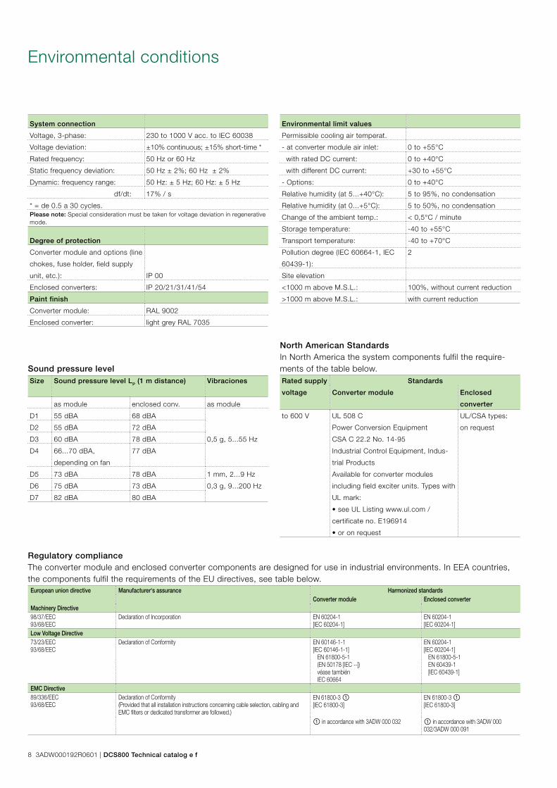
Environmental conditions
System connection
Voltage, 3-phase: 230 to 1000 V acc. to IEC 60038
Voltage deviation: ±10% continuous; ±15% short-time *
Rated frequency: 50 Hz or 60 Hz
Static frequency deviation: 50 Hz ± 2%; 60 Hz ± 2%
Dynamic: frequency range: 50 Hz: ± 5 Hz; 60 Hz: ± 5 Hz
df/dt: 17% / s
* = de 0.5 a 30 cycles.Please note: Special consideration must be taken for voltage deviation in regenerative mode.
Degree of protection
Converter module and options (line
chokes, fuse holder, field supply
unit, etc.): IP 00
Enclosed converters: IP 20/21/31/41/54
Paint finish
Converter module: RAL 9002
Enclosed converter: light grey RAL 7035
Sound pressure levelSize Sound pressure level LP (1 m distance) Vibraciones
as module enclosed conv. as module
D1 55 dBA 68 dBA
0,5 g, 5...55 Hz
D2 55 dBA 72 dBA
D3 60 dBA 78 dBA
D4 66...70 dBA,
depending on fan
77 dBA
D5 73 dBA 78 dBA 1 mm, 2...9 Hz
0,3 g, 9...200 HzD6 75 dBA 73 dBA
D7 82 dBA 80 dBA
Rated supply
voltage
Standards
Converter module Enclosed
converter
to 600 V UL 508 C
Power Conversion Equipment
CSA C 22.2 No. 14-95
Industrial Control Equipment, Indus-
trial Products
Available for converter modules
including field exciter units. Types with
UL mark:
• see UL Listing www.ul.com /
certificate no. E196914
• or on request
UL/CSA types:
on request
Regulatory complianceThe converter module and enclosed converter components are designed for use in industrial environments. In EEA countries, the components fulfil the requirements of the EU directives, see table below.European union directive Manufacturer‘s assurance Harmonized standards
Converter module Enclosed converterMachinery Directive98/37/EEC93/68/EEC
Declaration of Incorporation EN 60204-1[IEC 60204-1]
EN 60204-1[IEC 60204-1]
Low Voltage Directive73/23/EEC93/68/EEC
Declaration of Conformity EN 60146-1-1[IEC 60146-1-1] EN 61800-5-1 (EN 50178 [IEC --]) véase también IEC 60664
EN 60204-1[IEC 60204-1] EN 61800-5-1 EN 60439-1 [IEC 60439-1]
EMC Directive89/336/EEC93/68/EEC
Declaration of Conformity(Provided that all installation instructions concerning cable selection, cabling and EMC filters or dedicated transformer are followed.)
EN 61800-3 ①[IEC 61800-3]
EN 61800-3 ①[IEC 61800-3]
① in accordance with 3ADW 000 032 ① in accordance with 3ADW 000 032/3ADW 000 091
North American StandardsIn North America the system components fulfil the require-ments of the table below.
Environmental limit values
Permissible cooling air temperat.
- at converter module air inlet: 0 to +55°C
with rated DC current: 0 to +40°C
with different DC current: +30 to +55°C
- Options: 0 to +40°C
Relative humidity (at 5...+40°C): 5 to 95%, no condensation
Relative humidity (at 0...+5°C): 5 to 50%, no condensation
Change of the ambient temp.: < 0,5°C / minute
Storage temperature: -40 to +55°C
Transport temperature: -40 to +70°C
Pollution degree (IEC 60664-1, IEC
60439-1):
2
Site elevation
<1000 m above M.S.L.: 100%, without current reduction
>1000 m above M.S.L.: with current reduction
8 3ADW000192R0601 | DCS800 Technical catalog e f
��
��
��
��
��
��
M
��
��
��
��
����
�����
��������������� ����
������������
�����
� � � � � � � � � � � � � � � �
�
������������������
����
������������
� � � � � � � � � � � � � � � �
� � � � � � � � � � � � � � � �
� � � � � � � � � � � �
� � � � � � � � � � � �
������������
�������������
��
� ���
���
��
��
�
�
�
�
-ND
PA
-02
-ND
PC
-12
-NIS
A-0
3 (I
SA
)
ND
BU
95
(PC
MC
IA)
Mes
tre/
Esc
ravo AIMA
Slo
t1
Slo
t2
Slo
t3
ND
BU
95
������
�����
�����
� �
����
���
�
�
�
�
�
���
�
��
��
� ��
� ����
��
�
PC
+C
oD
eSys
DW
L
� �
���
� � � � � � � � � � � � � � � �
�����
��
��
���
���
���
���
���
�����
��
� � � � � � � � �
�������������������� ������������������
� ��������������������
����� ����
� ����� ������������
� � � � � � � � � � � � � � � � � � � � � � � � � �
����� ����������������
������
�����
�����
����������
PC
+D
rive
Win
do
wP
LC
�������
������
������
� � � � � �
Ad
van
tco
ntr
ol
��������
���������
������ �������
����
�� ����
�� ��������
� � � � � � � � � � � � � � � � � � � � � �������������
�������������
������������
�������������
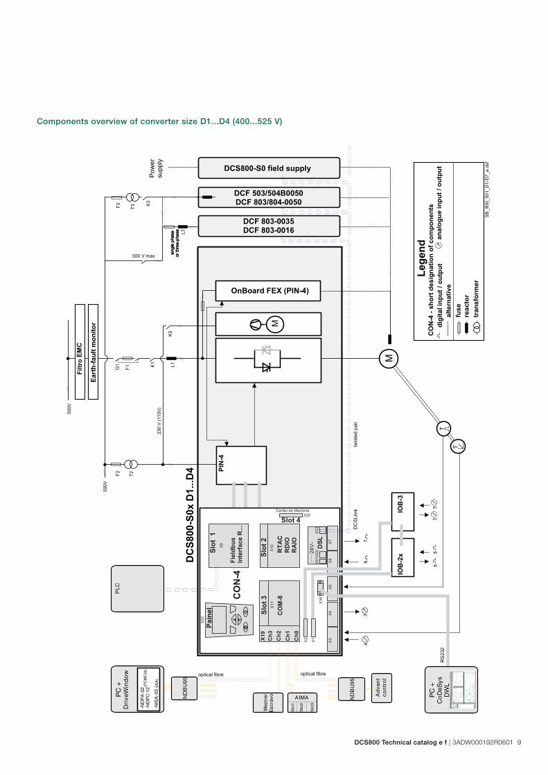
Components overview of converter size D1...D4 (400...525 V)
DCS800 Technical catalog e f | 3ADW000192R0601 9
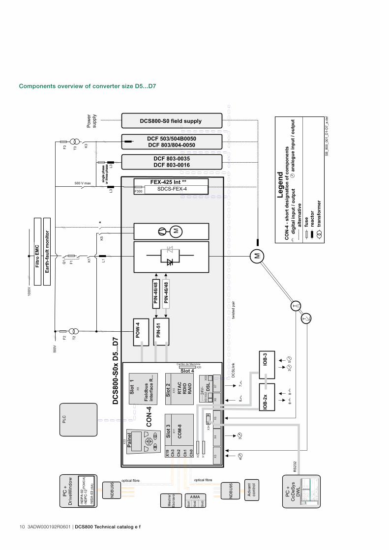
Components overview of converter size D5...D7
��
��
��
��
��
��
M
��
��
��
��
����
�����
��������������� ����
������������
� � � � � � � � � � � � � � � �
� � � � � � � � � � � � � � �
�� �
�� ��
�
�� �����
�� �����
��
������ �����������
�
������
� � � � � � � � � �� � � �
� � � � � � � � � � �
� � � � � � � � � � �
� � � � � � � � � � � �
��
�����
���
��
��
��
�
�
�
-ND
PA
-02
-ND
PC
-12
-NIS
A-0
3 (I
SA
)
ND
BU
95
(PC
MC
IA)
Mes
tre/
Esc
ravo AIMA
Slo
t1
Slo
t2
Slo
t3
ND
BU
95
�� ��
�� �
��� �
� �
���
��
��
��
��
��
��
��
�
���
��
���
���
����
������
���
���
PC
+C
oD
eSys
DW
L
� � �
���
� � � � � � � � � � � � � �
�����
���
���
���
���
���
���
���
��� �
���
� � � � � � � � �
��� �� ��������������������������������
�����������������������
�����������
����� ��������������
� � � � � � � � � � � � � � � � � � � � � �
����������������������
������
�����
���� �
�� ����� �
PC
+D
rive
Win
do
wP
LC
�������
������
������
� � � � � �
Ad
van
tco
ntr
ol
����� ��
���������
��������������
����
�������
�����������
� � � � � � � � � � � � � � � � � � � � �
�� ��� ������
�������������
�� ��� ������
�������������
10 3ADW000192R0601 | DCS800 Technical catalog e f

Quality dimensioningDriveSize is a PC program for helping the user to select an optimal converter and options, especially in those cases where a straightforward selection from a catalogue is not possible. Documents about the dimensioning based on actual load.
The default values make DriveSize simple to use, but the user is provided with many options for drive selection. The short-cut keys make drive selection easy while still honouring the relatively complicated rules. A manual selection mode is also supported.
DriveSize is currently used by more than 1000 engineers glob-ally.
DimensioningDriveSize
DriveSize is for drive system components – DCS converter modules – DCS enclosed converters – Group drives (line-ups) – Drive options
DriveSize features – Select an drive unit, incoming unit – Calculate duty load cycles for converters – Supply dimensioning results in graphical and numerical
format – Print and save the results
DCS800 Technical catalog e f | 3ADW000192R0601 11
Easy commissioning
GeneralEasy-to-use saves customer time consumption and keeps required training low. Easy commissioning is based on three columns.
– DCS800 is equipped with macros to cover the most fre-quent parameter settings.
– Assistance guide through required parameter setting dur-ing commissioning and all auto-tunings.
– Adaptive programming provides a very flexible set of func-tion blocks and solves problems during commissionig.
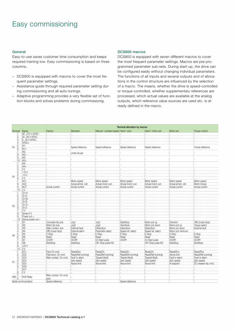
DCS800 macrosDCS800 is equipped with seven different macros to cover the most frequent parameter settings. Macros are pre-pro-grammed parameter sub-sets. During start-up, the drive can be configured easily without changing individual parameters. The functions of all inputs and several outputs and of alloca-tions in the control structure are influenced by the selection of a macro. The means, whether the drive is speed-controlled or torque-controlled, whether supplementary references are processed, which actual values are available at the analog outputs, which reference value sources are used etc. is al-ready defined in the macro.
Terminal allocation by macrosTerminal Signal Factory Standard Manual / constant speed Hand / auto Hand / motor pot Motor pot Torque control
X3:
1 90...270 V AITAC- - - - - - - -2 30...90 V AITAC- - - - - - - -3 8...30 V AITAC- - - - - - - -4 AITAC+ - - - - - - -5 AI1- - Speed reference Speed reference Speed reference Speed reference - Torque reference6 AI1+7 AI2- - Límite de par - - - - -8 AI2+9 AI3- - - - - - - -10 AI3+
X4:
1 AI4- - - - - - - -2 AI4+3 0 V - - - - - - -4 +10 V - - - - - - -5 -10 V - - - - - - -6 0 V - - - - - - -7 AO1 - Motor speed Motor speed Motor speed Motor speed Motor speed Motor speed8 AO2 - Actual armat. volt. Actual motor curr. Actual motor curr. Actual motor curr. Actual armat. volt. Motor torque9 IACT Actual current Actual current Actual current Actual current Actual current Actual current Actual current10 0 V - - - - - - -
X5:
1 Ch A+ - - - - - - -2 Ch A- - - - - - - -3 Ch B+ - - - - - - -4 Ch B- - - - - - - -5 Ch Z+ - - - - - - -6 Ch Z- - - - - - - -7 0 V - - - - - - -8 Sense 0 V - - - - - - -9 Power out + - - - - - - -10 Sence power out + - - - - - - -
X6:
1 DI1 Converter fan ack. Jog1 Jog1 StartStop Motor pot up Direction Off2 (coast stop)2 DI2 Motor fan ack. Jog2 Jog2 HandAuto Motor pot down Motor pot up Torque select3 DI3 Main contact. ack. External fault Direction Direction Direction Motor pot down External fault4 DI4 Off2 (coast stop) External alarm Parameter select Speed ref. select Speed ref. select Motor pot minimum -5 DI5 E-Stop E-Stop E-Stop E-Stop E-Stop E-Stop E-Stop6 DI6 Reset Reset Reset Reset Reset Reset Reset7 DI7 OnOff1 OnOff1 On Start pulse OnOff1 On Start pulse OnOff1 OnOff18 DI8 StartStop StartStop Off1 Stop pulse NC - Off1 Stop pulse NC StartStop StartStop9 +24 V - - - - - - -10 0 V - - - - - - -
X7:
1 DO1 Fans On cmd. ReadyRun ReadyOn ReadyOn ReadyOn ReadyRun ReadyRun2 DO2 Field excit. On cmd. ReadyRef (running) ReadyRef (running) ReadyRef (running) ReadyRef (running) Above limit ReadyRef (running)3 DO3 Main contact. On cmd. Fault or alarm Tripped (fault) Tripped (fault) Tripped (fault) Fault or alarm Fault or alarm4 DO4 - Zero speed Zero speed Zero speed Zero speed Zero speed Zero speed5 DO5 - Above limit Above limit Above limit Above limit At setpoint DC-breaker trip cmd. 6 DO6 - - - - - - -7 DO7 - - - - - - -8 0 V - - - - - - -
X96: 1 DO8 Relay Main contact. On cmd.ppal - - - - - -2
Serial communication Speed reference - - Speed reference - - -
12 3ADW000192R0601 | DCS800 Technical catalog e f
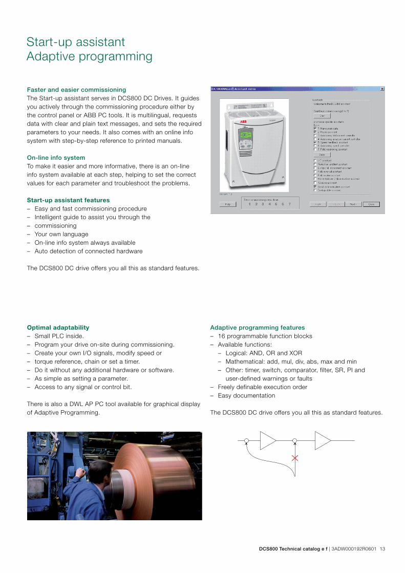
Optimal adaptability – Small PLC inside. – Program your drive on-site during commissioning. – Create your own I/O signals, modify speed or – torque reference, chain or set a timer. – Do it without any additional hardware or software. – As simple as setting a parameter. – Access to any signal or control bit.
There is also a DWL AP PC tool available for graphical display of Adaptive Programming.
Adaptive programming features – 16 programmable function blocks – Available functions:
– Logical: AND, OR and XOR – Mathematical: add, mul, div, abs, max and min – Other: timer, switch, comparator, filter, SR, PI and
user-defined warnings or faults – Freely definable execution order – Easy documentation
The DCS800 DC drive offers you all this as standard features.
Start-up assistantAdaptive programming
Faster and easier commissioningThe Start-up assistant serves in DCS800 DC Drives. It guides you actively through the commissioning procedure either by the control panel or ABB PC tools. It is multilingual, requests data with clear and plain text messages, and sets the required parameters to your needs. It also comes with an online info system with step-by-step reference to printed manuals.
On-line info systemTo make it easier and more informative, there is an on-line info system available at each step, helping to set the correct values for each parameter and troubleshoot the problems.
Start-up assistant features – Easy and fast commissioning procedure – Intelligent guide to assist you through the – commissioning – Your own language – On-line info system always available – Auto detection of connected hardware
The DCS800 DC drive offers you all this as standard features.
DCS800 Technical catalog e f | 3ADW000192R0601 13
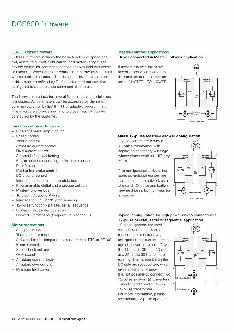
DCS800 basic firmwareDCS800 firmware includes the basic function of speed con-trol, armature current, field current and motor voltage. The flexible design for command location enables field bus control or master-follower control or control from hardware signals as well as a mixed structure. The design of drive logic enables a drive reaction defined by Profibus standard but can also configured to adapt classic command structures.
The firmware interface for several fieldbuses and module bus is included. All parameters can be accessed by the serial communication or by IEC 61131 or adaptive programming. Five macros are pre-defined and two user macros can be configured by the customer.
Functions of basic firmware – Different speed ramp function – Speed control – Torque control – Armature current control – Field current control – Automatic field weakening – E-stop function according to Profibus standard – Dual field control – Mechanical brake control – DC breaker control – Interface for fieldbus and module bus – Programmable digital and analogue outputs – Master-Follower bus – 16 blocks Adaptive Program – Interface for IEC 61131 programming – 12-pulse function - parallel, serial, sequential – 3-phase field exciter operation – Converter protection (temperature, voltage,...)
Motor protections – Stall protections – Thermal motor model – 2 channel motor temperature measurement PTC or PT100 – Klixon supervision – Speed feedback error – Over speed – Armature current ripple – Armature over current – Minimum field current
DCS800 firmware
Master-Follower applications Drives connected in Master-Follower application
If motors run with the same speed / torque connected to the same shaft or gearbox are called MASTER - FOLLOWER.
Quasi 12-pulse Master-Follower configurationThe converters are fed by a 12-pulse transformer with separated secondary windings whose phase positions differ by 30°el.
This configuration delivers the same advantages concerning harmonics to the network as a standard 12- pulse application (see next item), but no T-reactor is needed.
Typical configuration for high power drives connected in 12-pulse parallel, serial or sequential application12-pulse systems are used for reduced line harmonics, reduced motor noise level, enlarged output current or volt-age of converter system. Only the 11th and 13th, the 23rd and 25th, the 35th a.s.o. are existing. The harmonics on the DC side are reduced too, which gives a higher efficiency. It is not possible to connect two 12-pulse systems (2 converters, T-reactor and 1 motor) to one 12-pulse transformer. For more information, please see manual 12-pulse operation.
DSL
M
DSL
M
DSL link
D1 C1 C1 D1
Master-Follower
connectedvia load
MasterDCS800
FollowerDCS800
DSL
M
DSL
M
YD1 C1 C1 D1
quasi 12-pulse
Tandem motors
MasterDCS800
FollowerDCS800
DSL link
DSL
M
DSL
Y
M
D1 C1 C1 D1
DSL link
D1 C1 C1 D1
12-pulse parallel
12-pulse serial
MasterDCS800
FollowerDCS800
14 3ADW000192R0601 | DCS800 Technical catalog e f

Plug-in options
DCS800 - S01 - 0025 - 04 + B055
Plug-in fieldbus moduleThe plug-in fieldbus options bring connectivity to major auto-mation systems. A single twisted pair avoids large amounts of conventional cabling, thereby reducing cost and increas-ing system reliability. The fieldbus adapter must be located in Slot1.
For plus codes see Fieldbus control (page 21)
DCS800 Control PanelThe DCS800 Control Panel features three lines of numeric display. The panel can be used to control the drive, set the parameter values or copy them from a drive to another one. It comes with every DCS800.
plus code +0J400 If no control panel is required+J404 Panel mounting kit ACS/H-CP-EXT plus cable
I/O extension option moduleThis plug-in option offers two additional relay outputs. They can be used, for example, in a Master-Follower application for interlocking functions. All the relays can be programmed by parameters. Alternatively, the I/O options can be used to control any external components in the system.
plus code
+L501 RDIO-01 Digital extension module 3xDI, 2xDO+L500 RAIO-01 Analog extension module 2xAI, 2xAO
Fast optical DDCS communication moduleDCS800 provides an interface SDCS-COM-8 fast serial com-munication: – Master channel ModuleBus to AC800 M – I/O channel to AIMA-01 board – Master-Follower DDCS channel – Tools channel e.g DriveWindow, remote diagnostic NETA,
as well as the CDP 312 from ACS800 range can be con-nected on this board
– The board must be located in Slot3.
plus code +L508 Module bus 10 Mbd (SDCS-COM-81)+L509 NxxA fieldbus adapter 5 Mbd (SDCS-COM-82)
Drive-specific serial communication boardThe SDCS-DSL-4 board provides the serial communication for: – Drive-to-drive – Drive to external field exciters – 12-pulse applications – Master-Follower
plus code +S199 SDCS-DSL communication board
DCS800 Technical catalog e f | 3ADW000192R0601 15

General data – Currents from 0.3 to 520 A – Minimum field current monitor – Integrated external field power converter or completely
separate switchgear cubicle – single-phase or 3-phase model – Controlled by serial communication via DSLLink
All field converters are controlled by the armature converter via a serial interface (SDCS-DSL-4 board). This interface serves to parameterize, control and diagnose the field con-verter and thus provides exact control.
We recommend integrating an autotransformer in the field power converter’s supply circuit to adjust the AC input voltage to the field voltage and for reducing the voltage ripple in the field circuit for single-phase operation.
External field supply
Field converter typesDCF803-0035 e DCF803-0016 – Half-controlled thyristor/diode bridge (1-Q) – Three-phase or single-phase operation – Microprocessor control, with the electronic
system being supplied by the armature-circuit converter (24 V).
– Construction and components have been de-signed for an insulation voltage of 600 V AC.
– Fast-response excitation is possible with an appropriate voltage reserve; de-excitation takes place by field time constant.
– Field Output voltage UA (single-phase operation):
9.0*
%100%100*
+≤ TOLUU VA
TOL = tolerance of line voltage in % UV = Line voltage, UA = Field voltage
– Recommendation (single-phase operation): UA = 0.6 to 0.8 * UV or UV = 1.25 to 1.7 * UA
– Field Output voltage UA (three-phase operation):
53.1*%100
%100*
+≤ TOLUU VA
TOL = tolerance of line voltage in % UV = Line voltage, UA = Field voltage
Note: Calculation valid also for FEX-425 internal
Unit type Output
current ICC
AC field supply
voltage
auxiliary
supply voltage
Remarks
DCF803-0016 0,3...16 A 110 V -15 %...500 V / 1-ph +10 %
single-phase or three-phase
24 VDC
200 mA
external fuse
L3 line choke for 3-phase operation use:
ND401 ≤ 16 A
ND402 > 16 A
for 1-phase operation use:
ND30 ≤ 16 A
ND402 > 16 A
DCF803-0035 0,3...35 A 110 V -15 %...500 V / 1-ph +10 %
single-phase or three-phase
DCF803-0050 0,3...50 A 110 V -15 %...500 V / 1-ph +10 %
115 or 230 V
if necessary via matching autotransformer; fuse ex-
ternal; Dimensions HxWxD: 370x125x342 [mm]
DCF804-0050 0,3...50 A 110 V -15 %...500 V / 1-ph +10 %
DCS800-S0x-xxxx-05 see table on
page 7
200 V...500 V / 3-ph additional hardware components (DCF 506)
Current reduction see also Environmental conditions in Hardware manual
Table of field converter units
16 3ADW000192R0601 | DCS800 Technical catalog e f
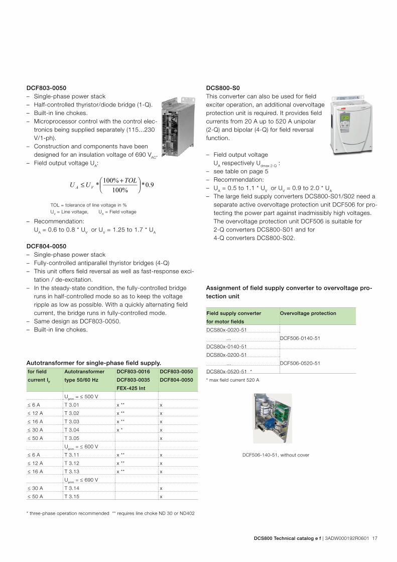
DCF803-0050 – Single-phase power stack – Half-controlled thyristor/diode bridge (1-Q). – Built-in line chokes. – Microprocessor control with the control elec-
tronics being supplied separately (115...230 V/1-ph).
– Construction and components have been designed for an insulation voltage of 690 VAC.
– Field output voltage UA:
9.0*%100
%100*
+≤ TOLUU VA
TOL = tolerance of line voltage in % UV = Line voltage, UA = Field voltage
– Recommendation: UA = 0.6 to 0.8 * UV or UV = 1.25 to 1.7 * UA
DCF804-0050 – Single-phase power stack – Fully-controlled antiparallel thyristor bridges (4-Q) – This unit offers field reversal as well as fast-response exci-
tation / de-excitation. – In the steady-state condition, the fully-controlled bridge
runs in half-controlled mode so as to keep the voltage ripple as low as possible. With a quickly alternating field current, the bridge runs in fully-controlled mode.
– Same design as DCF803-0050. – Built-in line chokes.
DCS800-S0This converter can also be used for field exciter operation, an additional overvoltage protection unit is required. It provides field currents from 20 A up to 520 A unipolar (2-Q) and bipolar (4-Q) for field reversal function.
– Field output voltage UA respectively Udmax 2-Q :
– see table on page 5 – Recommendation: – UA = 0.5 to 1.1 * UV or UV = 0.9 to 2.0 * UA
– The large field supply converters DCS800-S01/S02 need a separate active overvoltage protection unit DCF506 for pro-tecting the power part against inadmissibly high voltages. The overvoltage protection unit DCF506 is suitable for 2-Q converters DCS800-S01 and for 4-Q converters DCS800-S02.
DCF506-140-51, without cover
Assignment of field supply converter to overvoltage pro-tection unit
Field supply converter
for motor fields
Overvoltage protection
DCS80x-0020-51
DCF506-0140-51 ...
DCS80x-0140-51
DCS80x-0200-51
DCF506-0520-51 ...
DCS80x-0520-51 *
* max field current 520 A
for field
current IF
Autotransformer
type 50/60 Hz
DCF803-0016
DCF803-0035
FEX-425 Int
DCF803-0050
DCF804-0050
Uprim = ≤ 500 V
≤ 6 A T 3.01 x ** x
≤ 12 A T 3.02 x ** x
≤ 16 A T 3.03 x ** x
≤ 30 A T 3.04 x * x
≤ 50 A T 3.05 x
Uprim = ≤ 600 V
≤ 6 A T 3.11 x ** x
≤ 12 A T 3.12 x ** x
≤ 16 A T 3.13 x ** x
Uprim = ≤ 690 V
≤ 30 A T 3.14 x
≤ 50 A T 3.15 x
Autotransformer for single-phase field supply.
* three-phase operation recommended ** requires line choke ND 30 or ND402
DCS800 Technical catalog e f | 3ADW000192R0601 17

Fig. 1 Fig. 2 Fig. 3 Fig. 4 Fig. 5
Fuse connections
Recommended fuse connections see tables below.
Semiconductor type F1 fuses and fuse holders for AC and DC power lines(DCS800-S01 / DCS800-S02)The converter units are subdivided into two groups: – Unit sizes D1, D2, D3 and D4 with rated currents up to
1000 A require external line fuses. – In unit sizes D5, D6 and D7 with rated currents of 900 A to
5200 A, the semiconductor fuses are installed internally (no additional external semiconductor fuses are needed).
The table assigns the AC fuse types to the converter types. In case the converter should be equipped with DC fuses ac-cording to the hints use the same type of fuse used on the AC side now in the plus and minus line (only for sizes D1...D4). Blade type fuses are used for all the converters of con-struction type D1...D4 except the converters (610 A, 680 A, 740 A, 820 A, 900 A, 1000 A)
Type of converter Type Fuse holder Design
fig.
2-Q Converter 4-Q Converter
DCS800-S01-0020-04/05 DCS800-S02-0025-04/05 50A 660V UR OFAX 00 S3L 1
DCS800-S01-0045-04/05 DCS800-S02-0050-04/05 80A 660V UR OFAX 00 S3L 1
DCS800-S01-0065-04/05 DCS800-S02-0075-04/05 125A 660V UR OFAX 00 S3L 1
DCS800-S01-0090-04/05 DCS800-S02-0100-04/05 125A 660V UR OFAX 00 S3L 1
DCS800-S01-0125-04/05 DCS800-S02-0140-04/05 200A 660V UR OFAX 1 S3 2
DCS800-S01-0180-04/05 DCS800-S02-0200-04/05 250A 660V UR OFAX 1 S3 2
DCS800-S01-0230-04/05 DCS800-S02-0260-04/05 315A 660V UR OFAX 2 S3 2
DCS800-S01-0315-04/05 DCS800-S02-0350-04/05 500A 660V UR OFAX 3 S3 3
DCS800-S01-0405-04/05 DCS800-S02-0450-04/05 700A 660V UR OFAX 3 S3 4
DCS800-S01-0470-04/05 DCS800-S02-0520-04/05 700A 660V UR OFAX 3 S3 4
DCS800-S01-0610-04/05 DCS800-S02-0680-04/05 900A 660V UR 3x 170H 3006 5
DCS800-S01-0740-04/05 DCS800-S02-0820-04/05 900A 660V UR 3x 170H 3006 5
DCS800-S01-0900-04/05 DCS800-S02-1000-04/05 1250A 660V UR 3x 170H 3006 5
DCS800-S01-0290-06 DCS800-S02-0320-06 500A 660V UR OFAX 3 S3 3
DCS800-S01-0590-06 DCS800-S02-0650-06 900A 660V UR 3x 170H 3006 5
Fuses and fuse holders (details see Technical Data)
18 3ADW000192R0601 | DCS800 Technical catalog e f

Line reactors L1
DCS Type
400V-690V
50/60 Hz
Line choke
1% relative voltage
drop
Design
Fig.
Line choke
4%
relative voltage drop
Design
Fig.
2-Q Converter 4-Q Converter
DCS800-S01-0020-04/05 DCS800-S02-0025-04/05 ND01 1 ND401 4
DCS800-S01-0045-04/05 DCS800-S02-0050-04/05 ND02 1 ND402 4
DCS800-S01-0065-04/05 DCS800-S02-0075-04/05 ND04 1 ND403 5
DCS800-S01-0090-04/05 DCS800-S02-0100-04/05 ND06 1 ND404 5
DCS800-S01-0125-04/05 DCS800-S02-0140-04/05 ND06 1 ND405 5
DCS800-S01-0180-04/05 DCS800-S02-0200-04/05 ND07 2 ND406 5
DCS800-S01-0230-04/05 DCS800-S02-0260-04/05 ND07 2 ND407 5
DCS800-S01-0290-06 DCS800-S02-0320-06 ND08 2 on request -
DCS800-S01-0315-04/05 DCS800-S02-0350-04/05 ND09 2 ND408 5
DCS800-S01-0405-04/05 DCS800-S02-0450-04/05 ND10 2 ND409 5
DCS800-S01-0590-06 DCS800-S02-0650-06 ND13 3 on request -
DCS800-S01-0470-04/05 DCS800-S02-0520-04/05 ND10 2 ND410 5
DCS800-S01-0610-04/05 DCS800-S02-0680-04/05 ND12 2 ND411 5
DCS800-S01-0740-04/05 DCS800-S02-0820-04/05 ND13 3 ND412 5
DCS800-S01-0900-04/05 DCS800-S02-1000-04/05 ND13 3 ND413 5
DCS800-S01-0900-06/07 DCS800-S02-0900-06/07 ND13 3 on request -
DCS800-S01-1200-04/05 DCS800-S02-1200-04/05 ND14 3 on request -
DCS800-S01-1500-04/05/06/07 DCS800-S02-1500-04/05/06/07 ND15 3 on request -
DCS800-S01-2000-04/05 DCS800-S02-2000-04/05 ND16 3 on request -
DCS800-S01-2000-06/07 ND16 * 3 on request -* with forced cooling
Fig. 1 Fig. 2 Fig. 3
Fig. 4 Fig. 5
DCS800 Technical catalog e f | 3ADW000192R0601 19

IEC 61131 programming
ControlBuilder DCS800The ControlBuilder is a user-friendly tool based on the IEC61131-3 standard for programming the DCS800. With the ControlBuilder it is possible to develop - in a fast and easy way - new function e.g. winders, decentralized controls, safety functions, … directly in the drive.
The ControlBuilder is based on the common tool CoDeSys. Due to its intuitive Windows based user interface even begin-ners are able to start programming immediately. Additionally a set of drive specific function blocks eases the programming of the DCS800.
By means of completely supporting all five programming lan-guages of the IEC61131-3 standard everyone is able to find the right programming environment: – instruction list IL – sequential function chart AS – function block diagram FDB – structured text ST – ladder diagram LD – additionally a free graphical function plan (CFC) is available
The extremely user-friendly online debugging function offers besides single step-, single cycle- and breakpoint mode an event triggered recording tool for variables and signals.
Requirements – PC with Windows NT, 2000 or XP – One free serial port
Advantages of the ControlBuilder DCS800 – Fast and easy adaptation of DCS800 DC Drive to the used
application. – Less spare parts. – The application, including source code, is always part of
the drive and thus can be maintained during the whole live cycle of the machine.
– The source code can be password protected against unau-thorized access.
Due to the offline simulation mode it is possible to use the debugging function without connected hardware.
The application program is stored on a compact flash (Memo-ry Card), which is plugged into the drive. Thus it is possible to store the binary code as well as all source codes. Of course protection of the application program with a password is pos-sible.
Memory Card
Programming
Motor
Application
Member of Automation Alliance
20 3ADW000192R0601 | DCS800 Technical catalog e f
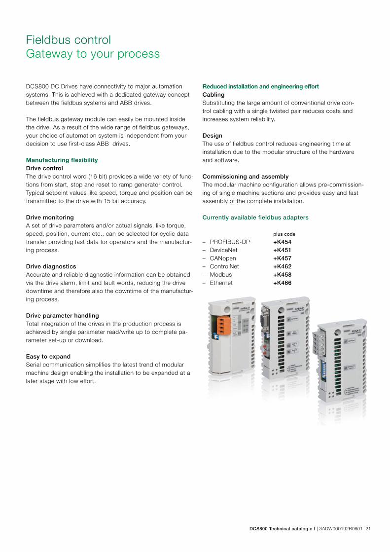
Fieldbus controlGateway to your process
DCS800 DC Drives have connectivity to major automation systems. This is achieved with a dedicated gateway concept between the fieldbus systems and ABB drives.
The fieldbus gateway module can easily be mounted inside the drive. As a result of the wide range of fieldbus gateways, your choice of automation system is independent from your decision to use first-class ABB drives.
Manufacturing flexibilityDrive controlThe drive control word (16 bit) provides a wide variety of func-tions from start, stop and reset to ramp generator control. Typical setpoint values like speed, torque and position can be transmitted to the drive with 15 bit accuracy.
Drive monitoringA set of drive parameters and/or actual signals, like torque, speed, position, current etc., can be selected for cyclic data transfer providing fast data for operators and the manufactur-ing process.
Drive diagnosticsAccurate and reliable diagnostic information can be obtained via the drive alarm, limit and fault words, reducing the drive downtime and therefore also the downtime of the manufactur-ing process.
Drive parameter handlingTotal integration of the drives in the production process is achieved by single parameter read/write up to complete pa-rameter set-up or download.
Easy to expandSerial communication simplifies the latest trend of modular machine design enabling the installation to be expanded at a later stage with low effort.
Reduced installation and engineering effortCablingSubstituting the large amount of conventional drive con-trol cabling with a single twisted pair reduces costs and increases system reliability.
DesignThe use of fieldbus control reduces engineering time at installation due to the modular structure of the hardware and software.
Commissioning and assemblyThe modular machine configuration allows pre-commission-ing of single machine sections and provides easy and fast assembly of the complete installation.
Currently available fieldbus adapters
plus code – PROFIBUS-DP +K454 – DeviceNet +K451 – CANopen +K457 – ControlNet +K462 – Modbus +K458 – Ethernet +K466
DCS800 Technical catalog e f | 3ADW000192R0601 21
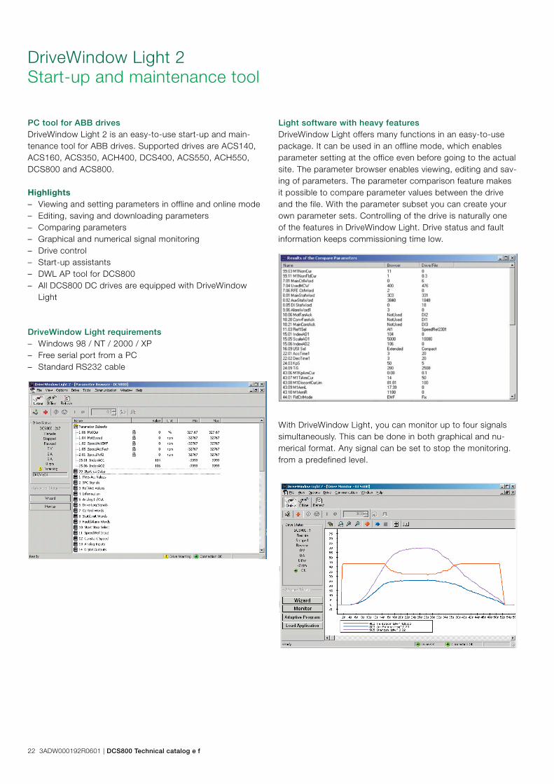
DriveWindow Light 2Start-up and maintenance tool
PC tool for ABB drivesDriveWindow Light 2 is an easy-to-use start-up and main-tenance tool for ABB drives. Supported drives are ACS140, ACS160, ACS350, ACH400, DCS400, ACS550, ACH550, DCS800 and ACS800.
Light software with heavy featuresDriveWindow Light offers many functions in an easy-to-use package. It can be used in an offline mode, which enables parameter setting at the office even before going to the actual site. The parameter browser enables viewing, editing and sav-ing of parameters. The parameter comparison feature makes it possible to compare parameter values between the drive and the file. With the parameter subset you can create your own parameter sets. Controlling of the drive is naturally one of the features in DriveWindow Light. Drive status and fault information keeps commissioning time low.
DriveWindow Light requirements – Windows 98 / NT / 2000 / XP – Free serial port from a PC – Standard RS232 cable
Highlights – Viewing and setting parameters in offline and online mode – Editing, saving and downloading parameters – Comparing parameters – Graphical and numerical signal monitoring – Drive control – Start-up assistants – DWL AP tool for DCS800 – All DCS800 DC drives are equipped with DriveWindow
Light
With DriveWindow Light, you can monitor up to four signals simultaneously. This can be done in both graphical and nu-merical format. Any signal can be set to stop the monitoring. from a predefined level.
22 3ADW000192R0601 | DCS800 Technical catalog e f

DWL AP toolDWL AP is a graphical PC tool to create, document, edit and download Adaptive Programs. DWL AP supports Adaptive Programming of DCS800. Adaptive Program contains 16 function blocks and is available in standard firmware. DWL AP offers a clear and easy way to develop, test and document these programs with a PC.
It is a user-friendly tool to modify function blocks and their connections. No special programming skills are required, ba-sic knowledge about block programming is sufficient.
Adaptive Programs are easy to document as hard copies or store as PC files. All related information is saved directly to the drive by parameter.
DWL Start-up assistantDWL Start-up assistant for DCS800 gives important assis-tance for commissioning by interactive dialog. The commis-sioning steps are presented in correct sequence and neces-sary parameters are preselected. The basic port collects basic motor and connection data and executes controller auto tunings. The advanced port provides assistance for 12-pulse op-eration, field reversal, serial communication (fieldbus) and master-follower configuration. A context-sensitive help function is present during the whole sequence.
One page is freely configurable by the user. An individual commissioning sequence or parameter selection can be setup to application, machine or motor demands.
DCS800 Technical catalog e f | 3ADW000192R0601 23

Start-up and maintenance toolABB’s DriveWindow is an advanced, easy-to-use PC software tool for the start-up and maintenance of ABB DCS800 DC Drives. Its host of features and clear, graphical presentation of the operation make it a valuable addition to your system pro-viding information necessary for troubleshooting, maintenance and service, as well as training.
With DriveWindow the user is able to follow the co-operation of several drives simultaneously by collecting the actual values from the drives onto a single screen or printout.
Additionally, the client part of DriveWindow may reside on one Local Area Network PC, and the server side on another PC closer to the drives. This enables plant-wide monitoring to be easily accomplished with two PCs.
High speed communicationDriveWindow uses a high-speed fibre optic cable network with DDCS communication protocol.
This makes communication between PC and drives very fast. The fibre optic network is safe and extremely immune against external disturbance. The fibre optic communication card is needed inside the computer.
Versatile back-up functionsDrive parameters can be saved to the PC with DriveWindow, and can easily be downloaded back to the drive whenever needed.
DriveWindow 2 featuresEasy-to-use tool for commissioning and maintenance. Several drives connected and monitored at the same time. Monitor, edit or save signals and parameters, clear graphical presentation. High-speed communication between PC and drive. Versatile back-up functions. View data collected and stored in the drive. Fault diagnosis; DriveWindow indicates the status of drives, and also reads fault history data from the drive.
Start-up, maintenance and integrationDriveWindow 2
Monitoring drivesUsing DriveWindow you can monitor several drives simultane-ously. The history buffer makes it possible to record a large amount of data in the PC‘s memory. The drive‘s data logger can be accessed with DriveWindow and viewed in graphical form. The fault logger inside the drive automatically docu-ments every fault, warning and event which occurs. The fault history stored in the drive can be uploaded to your computer.
24 3ADW000192R0601 | DCS800 Technical catalog e f
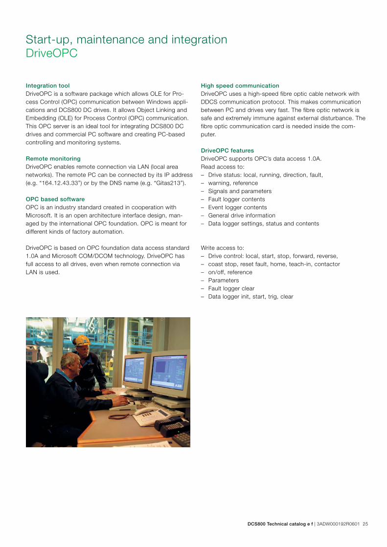
Integration toolDriveOPC is a software package which allows OLE for Pro-cess Control (OPC) communication between Windows appli-cations and DCS800 DC drives. It allows Object Linking and Embedding (OLE) for Process Control (OPC) communication. This OPC server is an ideal tool for integrating DCS800 DC drives and commercial PC software and creating PC-based controlling and monitoring systems.
Remote monitoringDriveOPC enables remote connection via LAN (local area networks). The remote PC can be connected by its IP address (e.g. “164.12.43.33”) or by the DNS name (e.g. “Gitas213”).
OPC based softwareOPC is an industry standard created in cooperation with Microsoft. It is an open architecture interface design, man-aged by the international OPC foundation. OPC is meant for different kinds of factory automation.
DriveOPC is based on OPC foundation data access standard 1.0A and Microsoft COM/DCOM technology. DriveOPC has full access to all drives, even when remote connection via LAN is used.
High speed communicationDriveOPC uses a high-speed fibre optic cable network with DDCS communication protocol. This makes communication between PC and drives very fast. The fibre optic network is safe and extremely immune against external disturbance. The fibre optic communication card is needed inside the com-puter.
DriveOPC featuresDriveOPC supports OPC’s data access 1.0A.Read access to: – Drive status: local, running, direction, fault, – warning, reference – Signals and parameters – Fault logger contents – Event logger contents – General drive information – Data logger settings, status and contents
Write access to: – Drive control: local, start, stop, forward, reverse, – coast stop, reset fault, home, teach-in, contactor – on/off, reference – Parameters – Fault logger clear – Data logger init, start, trig, clear
Start-up, maintenance and integrationDriveOPC
DCS800 Technical catalog e f | 3ADW000192R0601 25
Service productsTo reduce the total cost of owning ABB drives and to maxi-mize their availability ABB offers the following services:
Training servicesABB offers dedicated training on ABB drives for your service and operating personnel. Upon successful completion of the training course your personnel will have acquired the skills to use ABB drives correctly and safely, and also to get the best results from their application.
Service product
code
Service type Description
G560 DCS800 - 3 days Basic training
G561 DCS800 - 1 day Startup & Service Hands-on
ABB has a service organization that spans the globe. Contact your local ABB sales office for more information about our services.
www.abb.com/abbuniversity
Startup servicesUsing ABB’s startup services you can trust that your drives are correctly commissioned and well-tuned to their applica-tion. ABB employs authorized professionals who have been thoroughly trained for their job.
ABB maintenance servicesABB maintenance services ensure optimal operation of your drives and extend their useful life.
Spare part servicesABB offers a fast and effortless information and ordering sys-tem to facilitate spare part management. Parts OnLine is at your service 24 hours.
http://www.abb.com/partsonline
Remote monitoring toolEthernet module
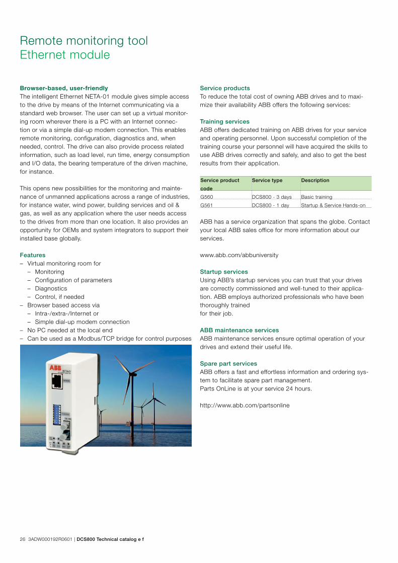
Browser-based, user-friendlyThe intelligent Ethernet NETA-01 module gives simple access to the drive by means of the Internet communicating via a standard web browser. The user can set up a virtual monitor-ing room wherever there is a PC with an Internet connec-tion or via a simple dial-up modem connection. This enables remote monitoring, configuration, diagnostics and, when needed, control. The drive can also provide process related information, such as load level, run time, energy consumption and I/O data, the bearing temperature of the driven machine, for instance.
This opens new possibilities for the monitoring and mainte-nance of unmanned applications across a range of industries, for instance water, wind power, building services and oil & gas, as well as any application where the user needs access to the drives from more than one location. It also provides an opportunity for OEMs and system integrators to support their installed base globally.
Features – Virtual monitoring room for
– Monitoring – Configuration of parameters – Diagnostics – Control, if needed
– Browser based access via – Intra-/extra-/Internet or – Simple dial-up modem connection
– No PC needed at the local end – Can be used as a Modbus/TCP bridge for control purposes
26 3ADW000192R0601 | DCS800 Technical catalog e f

DCS family
– Compact – Robust design – Adaptive and winder program – High field exciter current
– Compact – Highest power ability – Simple operation – Comfortable assistants, e.g. for commissioning or
fault tracing – Scalable to all applications – Free programmable by means of integrated
IEC61131-PLC
– Individually adaptable to customer requirements – User-defined accessories like external PLC or auto-
mation systems can be included – High power solutions in 6- and 12-pulse up to
20,000 A, 1,500 V – In accordance to usual standards – Individually factory load tested – Detailed documentation
– DCS800 module with all necessary accessories mounted and fully cabled on a panel
– Very fast installation and commissioning – Squeezes shut-down-times in revamp projects to a
minimum – Fits into Rittal cabinets – Compact version up to 450 A and Vario version up
to 2,000 A
– Proven long life components are re-used, such as power stacks, (main) contactors, cabinets and cabling / busbars, cooling systems
– Use of up-to-date communication facilities – Increase of production and quality – Very cost-effective solution – Open Rebuild Kits for nearly all existing DC drives – tailor-made solutions for…
• BBC PxD • BBC SZxD • ASEA TYRAK • other manufacturers
DCS550-S modulesThe compact drive for machinery application
20 … 1,000 ADC
0 … 610 VDC
230 … 525 VAC
IP00
DCS800-S modulesThe versatile drive for processindustry
20 … 5,200 ADC
0 … 1,160 VDC
230 … 1,000 VAC
IP00
DCS800-A enclosed convertersComplete drive solutions
20 … 20,000 ADC
0 … 1,500 VDC
230 … 1,200 VAC
IP21 – IP54
DCS800-E seriesPre-assembled drive-kits
20 … 2,000 ADC
0 … 700 VDC
230 … 600 VAC
IP00
DCS800-R Rebuild KitDigital control-kit for existing powerstacks
20 … 20,000 ADC
0 … 1,160 VDC
230 … 1,200 VAC
IP00
DCS800 Technical catalog e f | 3ADW000192R0601 27

ABB Automation Products GmbHMotors and DrivesWallstadter Straße 59 D-68526 Ladenburg Germany Phone: +49 (0) 6203 717 608 Fax: +49 (0) 6203 717 609 [email protected]/motors&drives
Contact us
© C
opyr
ight
201
2 A
BB
. All
right
s re
serv
ed.
3AD
W00
0192
R06
01 R
ev F
03
.201
2
Spe
cific
atio
ns s
ubje
ct to
cha
nge
with
out n
otic
e.