Catalog 1600-5 Daikin Classroom Unit Ventilators · AHRI Performance Table 1: AHRI Performance Data...
108
Catalog 1600-5 Daikin Classroom Unit Ventilators Models AVS, AVB, AVV and AVR Floor Units
Transcript of Catalog 1600-5 Daikin Classroom Unit Ventilators · AHRI Performance Table 1: AHRI Performance Data...

Catalog 1600-5Daikin Classroom Unit Ventilators Models AVS, AVB, AVV and AVR Floor Units

Contents
Introduction ............................................................................. 3Daikin Classroom Unit Ventilators ..................................... 3
AHRI Performance .................................................................. 4Unit Features........................................................................... 5
Model AV Floor Unit ........................................................... 5
Features & Benefits ................................................................ 6Quiet Operation With Our GentleFlo Delivery ................... 6The Right Amount of Fresh Air and Cooling ...................... 7Precise Temperature and Dehumidification Control .......... 8Low Installation Costs ..................................................... 10Perfect For Both New & Retrofit Applications ..................................................................... 10Built In Flexibility.............................................................. 10Controls Flexibility ........................................................... 10Low Operating Costs .......................................................11Easy To Maintain ............................................................ 12Built To Last .................................................................... 14Durable, Energy Efficient Fan Motors ............................ 15
General Data ......................................................................... 16Model Nomenclature ....................................................... 16Model Types .................................................................... 18Available Unit Ventilator Combinations ........................... 19Unit Arrangements: 16-5/8" Deep .................................. 22Unit Arrangements: 21-7/8" Deep .................................. 22MicroTech II Controls....................................................... 25Digital Ready Systems .................................................... 26Field Mounted Controls (By Others) ................................ 26Variable Airflow Control ................................................... 26Economizer Modes.......................................................... 26Demand Control Ventilation............................................. 26
Accessories .......................................................................... 27Unit Arrangements AL: 21-7/8" Deep With Accessories .. 27End Panels, Filler Sections & Sub Bases ....................... 28Wall Louvers & Grilles .................................................... 28VentiMatic™ Shutter – Room Exhaust Ventilation ......... 30Window Downdraft Protection ........................................ 30
Physical Data ........................................................................ 32Models AVS, AVB, AVV and AVR ..................................... 32
Details & Dimensions ........................................................... 3316-5/8" Deep Unit Arrangements .................................... 3321-7/8" Deep Unit Arrangements .................................... 34Unit Arrangement Accessories ........................................ 39
Coil Connections .................................................................. 41General............................................................................ 41
Heat/Cool Units ..................................................................... 42Reheat Units.......................................................................... 44Heating Only Units ............................................................... 46Cooling Only Units ............................................................... 46
Condensate Drain Locations ........................................... 46
End Panels ............................................................................ 47End Panel – Dimensions ................................................. 47
Valves .................................................................................... 48Face & Bypass End of Cycle Valves ............................... 48Modulating Valves ........................................................... 48
Wall Louvers ........................................................................ 49Wall Intake Louvers & Grilles .......................................... 49
VentiMatic Shutter ................................................................ 50VentiMatic Shutter Assembly ........................................... 50
Performance and Selection ................................................. 51Quick Selection Procedure .............................................. 51Chilled Water Selection Example .................................... 53Hot Water Heating Selection ........................................... 55Quick Selection Method Using MBH/ΔT .......................... 55Two-Pipe Chilled-Water/Hot-Water Applications ..................................................................... 55Steam Heating Selection ................................................. 58Electric Heating Selection ............................................... 59Direct Expansion Cooling Coil Selection ......................... 60
Electrical Data ....................................................................... 61PSC Motor ....................................................................... 61EC Motor ......................................................................... 62
Wiring Diagrams ................................................................... 63Typical Wall Sensors Diagram ........................................ 64Power & Control Field Wiring .......................................... 64Typical Digital Ready Wiring Diagram – PSC Motor ....... 66Typical Controls By Others Wiring Diagram – PSC Motor ....................................................................... 67Typical Controls By Others Wiring Diagram – Units with EC Motor ......................................................................... 68Typical Controls By Others Wiring Diagram – Units with EC Motor Variable Airflow ................................................ 69
MicroTech II Controls ........................................................... 70Control Modes and Functions ........................................ 70Advanced Control Options ............................................. 72System Components ....................................................... 73Unit Ventilator Controller ................................................ 73Optional Time Clock For Stand-Alone Operation ........................................................................ 75Sensors .......................................................................... 75Actuators ........................................................................ 76ServiceTools™ ................................................................ 77Optional Communication Modules ................................. 78
Application Considerations ................................................. 79Why Classrooms Overheat ............................................ 79Meeting IAQ Requirements ............................................ 80Following ASHRAE Control Cycle II ............................... 81Meeting AHRI 840 Requirements .................................... 82Face & Bypass Temperature Control ............................. 83Modulating Valve Temperature Control .......................... 85Coil Selection ................................................................. 86DX Split Systems ............................................................ 87Digital Ready Systems ................................................... 89Field-Installed Controls By Others & Digital Ready Controls .................................................... 89Unit Installation ................................................................ 94Wall Louvers ................................................................... 95Window Downdraft Protection ......................................... 98DraftStop System ............................................................ 98DraftStop Application ....................................................... 98Valve Selection ................................................................ 99Face and Bypass End-Of-Cycle Valve Sizing & Piping ... 99Modulating Valve Sizing & Piping .................................. 101Steam Valve Sizing & Piping ........................................ 103
Guide Specifications .......................................................... 105Daikin Applied Unit Ventilator – Model AV Guide Specifications ............................................................... 105
CAT 1600-5 • MODEL AV UNIT VENTILATOR 2 www.DaikinApplied.com

Introduction
Daikin Classroom Unit Ventilators
For nearly a century schools have relied on unit ventila-tors to keep classrooms comfortable. Students learn more readily in a quiet, well-ventilated environment. That is why Herman Nelson invented the unit ventilator in 1917. Daikin Applied continues to set the industry standard for perfor-mance, features and quality. Today Daikin remains commit-ted to continuing the Herman Nelson-AAF-McQuay legacy as the industry leader and meeting the changing require-ments of schools with the highest quality unit ventilator products available.We realize that keeping expenditures down is a high prior-ity for school administrators and school boards.Daikin unit ventilators are inexpensive to install and oper-ate, and they are designed and built to provide decades of trouble-free service.
Quiet OperationDaikin unit ventilators are engineered and manufactured to deliver quiet, continuous comfort. We developed our GentleFlo™ air moving system to minimize operating sound levels—even as demands for more fresh air re-quire units to operate longer and work harder.
The Right Amount of Fresh Air and CoolingDaikin unit ventilators deliver required amounts of fresh air to meet ventilation requirements, and added cooling capacity to maintain consistent comfort for students and teachers. Our Economizer Operation, Demand Control Ventilation (DCV) and Part Load, Variable Air options allow you to closely match comfort requirements and reduce operating costs.
Precise Temperature and Dehumidification Con trategies, they provide precise control of tempera-ture and humidity levels.
Low Installation CostsNew construction installations are easily accomplished with Daikin unit ventilators because they avoid the added cost and space required for expensive ductwork. Retro-fit installations are also economical because new units fit the same space occupied by existing ones. Multiple control options—includingMicroTech II controls with Protocol Selectability™, or Digi-tal Ready™ features—provide easy, low cost integration into the building automation system of your choice.
Low Operating CostsWhen running, Daikin unit ventilators can use as little electricity as two 100-watt light bulbs. They take maxi-mum advantage of “free” cooling opportunities to reduce operating costs. During unoccupied periods and at night, units operate sparingly to conserve energy.
Easy To Maintain, Modular DesignDaikin Unit Ventilators are designed to provide easy access for maintenance and service personnel to all serviceable components. Most tasks are easily handled by a single person.
Built To LastOur proven institutional design can withstand the rigors of the classroom environment. It features an extra-sturdy chassis and double-wall damper on the inside; scuff-resistant finishes and tamper prevention features on the outside. In fact, many units installed over 30 years ago continue to provide quiet, reliable classroom comfort.
MicroTech II Control For Superior Performance, Easy IntegrationDaikin unit ventilators can be equipped with MicroTech™ II unit controllers for superior performance. Factory inte-grated and tested controller, sensor, actuator and unit op-tions promote quick, reliable start-up and minimize costly field commissioning. Our Protocol Selectability feature provides easy, low-cost integration into most building au-tomation systems. Select BACnet®, or LonTalk® to com-municate control and monitoring information to your BAS, without the need for costly gateways. Unit controllers are LONMARK® certified with the optional LonWorks® communication module.
www.DaikinApplied.com 3 CAT 1600-5 • MODEL AV UNIT VENTILATOR

AHRI Performance
Table 1: AHRI Performance Data
Model Unit SizeNominal Airflow Cooling
Coil RowsTotal Capacity Sensible Capacity Temperature Rise Power
InputVentilation
Rate
CFM L/s Btuh Watt Btuh Watt F C Watts %
AVV, AVS
07 750 354
2-Row 15700 4601 11400 3341
10 12.2
216
803-Row 19000 5568 12900 3781 212
4-Row 24500 7180 15300 4484 207
5-Row 30800 9027 20300 5949 203
10 1000 472
2-Row 23600 6916 17800 5217
10 12.2
277
803-Row 33200 9730 22600 6623 277
4-Row 35600 10433 23300 6829 279
5-Row 35900 10521 23600 6916 280
13 1250 590
2-Row 31500 9232 23600 6916
10 12.2
335
803-Row 41000 12016 28600 8382 331
4-Row 43300 12690 28700 8411 327
5-Row 47200 13833 31100 9115 323
15 1500 708
2-Row 38700 11342 28400 8323
10 12.2
445
803-Row 51200 15005 34900 10228 431
4-Row 56700 16617 37100 10873 418
5-Row 57600 16881 36800 10785 380
Notes: Rated in accordance with AHRI Standard 840-98 for Unit Ventilators Capacity is based on 80°F db, 67°F wb entering air temperature, 45°F enter water temperature and high-speed fan.
Ventilation rate certified and tested per Air Conditioning, Heating and Refrigeration Institute (AHRI) Standard 840.

Unit FeaturesModel AV Floor UnitOur Model AV is a vertical, floor-standing unit that utilizes remotely-supplied chilled water or refrigerant for cooling, and hot water, steam or electric heat for heating. The Model AV also can be supplied as a heating/ventilating unit only or as a cooling/ventilating unit only.
The Model AV is just right for new construction and for retrofit applications. Older buildings with baseboard radi-ant heat or other hydronic heating systems can be easily adapted to work efficiently with Model AV units.Chilled-water or refrigerant cooling can be added to provide year-round comfort. The major features of this model are shown below and described in more detail on the following pages.
1
2
34
5
6
7
8
9
10
11
12
13
14
15
16
17
18
1 Welded one-piece chassis• offers superior strength, durability,
and vibration reduction
2 Unique draw-thru design• provides uniform air distribution
across the coil for even discharge air temperatures
3 Quiet, aerodynamic fans• utilize GentleFlo technology for
exceptionally quiet unit operation
4 Modular fan section• improves balance, alignment and
simplifies maintenance
5 Fan motor • located out of air stream and
away from heating coil reduces heat exposure to prolong life
6 Face and bypass damper design • provides superior dehumidification
and reduces chance of coil freeze-up
7 Certified ventilation performance per AHRI-840.
8 MicroTech II controls • provide superior comfort control and
easy integration into the building automation system of your choice.
9 Advanced heat transfer coil design provides extra capacity.
10 Sturdy cabinet construction • includes hidden reinforcement,
a nonglare textured surface, and a tough, scuff- and mar-resistant finish to make the top sturdy enough to support maintenance personnel.
11 Sectionalized front access panels • provide easy access to unit
interior. Panels are easily removed by a single person. Front side panels can be removed while unit is running.
12 Two hinged top access doors • provide easy access to motor
and end bearing. Special tamper-resistant fasteners deter unauthorized access.
13 Sampling chamber • for unit-mounted sensor provides
accurate sensing of room temperature.
14 Indoor room air damper • blocks unwanted gusts of
outdoor air on windy days. Its nylon bearings are quiet and maintenance free.
15 Insulated double-wall outdoor air damper• seals tightly without twisting.
16 Single full-length air filter • is efficient and easy to replace.
All air delivered to classroom is filtered.
17 Convertible drain pan • standard galvanized drain pan
has connections on either end, can be field-modified to slant in either direction. Available as a selectable option in stainless steel.
18 UL/cUL listed

Features & Benefits
CAT 1600-5 • MODEL AV UNIT VENTILATOR 6 www.DaikinApplied.com
Quiet Operation With Our GentleFlo DeliveryDaikin unit ventilators are engineered and manufactured to deliver quiet, continuous comfort. We developed our GentleFlo™ air moving system to minimize operating sound levels—even as demands for more fresh air re-quire units to operate longer and work harder. GentleFlo features include:• Fan wheels are large, wide and rotate at a low
speed to reduce fan sound levels. They are impact-resistant and carefully balanced to provide consistent performance.
• Offset, aerodynamic fan wheel blades move air efficiently (Figure 2).
Figure 1: GentleFlo Fan Technology
Offset Aerodynamic Blades
Logrithmic Expansion Housing
Precision Tolerances
Expanded Discharge Air Opening
• A large, expanded discharge opening minimizes air resistance, further lowering sound levels.
• Precision tolerances help reduce flow and pressure turbulence, resulting in lower sound levels.
• Fan housings incorporate the latest logarithmic expansion technology for smoother, quieter air flow (Figure 1).
• Modular fan construction contributes to equal outlet velocities and promotes quiet operation.
• Fan shafts are of ground and polished steel to minimize deflections and provide consistent, long-term operation.
• Fan assemblies are balanced before unit assembly, then tested after assembly (and rebalanced if necessary) to provide stable, quiet operation.
Figure 2: GentleFlo Reduces Turbulence
High TurbulenceMinimal
Turbulence
GentleFlo Fan Blade Design Typical Fan Blade Design
Offset Aerodynamic Blades

www.DaikinApplied.com 7 CAT 1600-5 • MODEL AV UNIT VENTILATOR
The Right Amount of Fresh Air and CoolingDaikin unit ventilators deliver required amounts of fresh air to meet ventilation requirements and added cooling capacity to maintain consistent comfort for students and teachers. Our Economizer Operation, Demand Control Ventilation (DCV) and Part Load, Variable Air options al-low you to match classroom comfort requirements even more closely, and reduce operating costs.This means that you can be confident that your school is meeting ventilation standards for Indoor Air Quality and that your students are receiving adequate air to be attentive to instruction. At the same time, you are saving money in early morning hours, between classes or after hours when classrooms are heated and cooled but not always fully occupied.
Economizer OperationIt is well recognized that cooling, not heating, is the main thermal challenge in school classrooms. The typical classroom is cooled by outdoor air over half the time, even in cold climates. It is therefore essential that unit ventilators efficiently deliver outdoor air when classroom conditions call for “free” or economizer cooling.With Daikin unit ventilators, you can have outdoor air whenever it is needed. Economizer operation is facili-tated by the outdoor air damper, which automatically ad-justs the above-minimum outside air position to provide free cooling when the outdoor air temperature is appro-priate (Figure 3). On units equipped with MicroTech II controls, three levels of economizer control are available (see page 70).Figure 3: Full Economizer Mode
Face & Bypass damper
Filter
Outdoor Air Damper
Outdoor Air
Room Air Damper
100% Outdoor Air Into Classroom
Part-Load Variable Air ControlPart Load Variable Air control can be used in conjunc-tion with face and bypass damper temperature control to automatically adjust the unit ventilator fan speed based upon the room load and the room temperature. This MicroTech II control option provides higher latent cooling capabilities and quieter operation during non-peak load periods by basing indoor fan speed upon room load.Lower fan speeds in conjunction with our GentleFlo fan technology (see page 6) contributes to a very quiet classroom environment.Room-temperature PI control loops determine the speed of the fan, which varies according to the room load. It also provides a built-in delay to prevent overshooting for better comfort control. The outdoor air damper’s mini-mum-air position is adjusted with the fan speed to bring in a constant amount of fresh air.
Demand Control VentilationDaikin unit ventilators can be equipped to use input from a CO2 controller to ventilate the space based on actual occupancy instead of a fixed design occupancy. This De-mand Controlled Ventilation (DCV) system monitors the amount of CO2 so enough fresh outdoor air is introduced to maintain good air quality. The system is designed to achieve a target ventilation rate (e.g., 15 cfm/person) based on actual occupancy.By using DCV to monitor the actual occupancy pattern in a room, the system can allow code-specific levels of outdoor air to be delivered when needed. Unnecessary over-ventilation is avoided during periods of low or inter-mittent occupancy, leading to improved energy efficien-cies and cost savings.
Features & Benefits

CAT 1600-5 • MODEL AV UNIT VENTILATOR 8 www.DaikinApplied.com
Precise Temperature and Dehumidification ControlDaikin unit ventilators provide precise temperature and dehumidification control to keep students and teachers comfortable while making maximum use of “free” out-door-air cooling to reduce operating costs. They utilize a draw-thru fan design that contributes to even heat trans-fer and provides uniform discharge air temperatures into the classroom. Coupled with face and bypass damper air control and/or our MicroTech II active and passive dehumidification control strategies, they provide precise control of temperature and humidity levels under both part-load and full-load conditions.
Draw-Thru Design For Even Discharge TemperaturesThe Draw-Thru design sets our unit ventilators apart from most competitive models. With this system, fans draw air through the entire heat transfer element (Figure 4) rather than blowing it through highly concentrated areas of the coil element. The result is more uniform discharge air temperatures into the classroom and more efficient unit ventilator operation.Figure 4: Draw-Thru Design Provides Even Discharge Air
Motor
Coil
Fans
Uniform Discharge Air (Shaded)
Face & Bypass Design For Better Temperature and Humidity ControlWhen coupled with our draw-thru design, face and bypass damper air control offers maximum dehumidifi-cation and optimal temperature control. That’s because indoor and outdoor air streams can be separated until it is optimal to mix them.During most part-load conditions, humid outdoor air is directed through the cold coil (coil surface below the dew point) where moisture is removed. Room air is bypassed around the coil, since it has already been dehumidi-fied. This arrangement allows for maximum condensate removal. Humid outdoor air is not bypassed around the coil until the total amount of cooling air required is less than the total amount of fresh outdoor air required in the room. Figure 5 and Figure 6 below compare the compo-sition of the air streams through the coil and air streams bypassing the coil at various bypass air percentages for
draw-thru and blow-thru unit ventilators using 450 cfm of outdoor air. At both 0% bypass air and 100% bypass air, no difference exists in the composition of the air streams. However, at all other bypass air percentages (part load), significant differences are evident. For instance, compare the 1500 cfm draw-thru (Figure 5) and blow-thru (Figure 6) units at 70% bypass air. At this point, the draw-thru unit still has all of the outdoor air going through the coil. Meanwhile, the blow-thru unit is bypass-ing 70% (315 cfm) of the humid outdoor air directly into the classroom.Figure 5: Daikin Applied 1500 CFM Draw-Thru Unit
Figure 6: 1500 CFM Typical Blow-Thru Design
Features & Benefits

www.DaikinApplied.com 9 CAT 1600-5 • MODEL AV UNIT VENTILATOR
This illustrates that the most effective way to maintain an acceptable humidity level with a chilled-water unit ventilator system is to use a face and bypass damper, draw-thru unit.
Why Blow-Thru Designs Don’t Measure UpBlow-thru designs cannot provide comfort like this. With blow-thru designs, the humid outside air is pre-mixed with the room air before it can go through the coil (Figure 7). Dehumidification occurs only to the portion of the air that is directed unevenly through the cooling coil. The air that bypasses the coil is largely humid outdoor air, resulting in unconditioned air being bypassed and creating poor comfort conditions.Figure 7: Draw-Thru Vs. Blow-Thru Design
Room Air
Damper
Outdoor Air Outdoor AirRoom Air
Filter
Room Air
Outdoor Air Damper
Face & Bypass Damper
Coil
Coil
With a blow-thru design the positive pressure of the fan discharge can create areas across the coil of varying tem-peratures and airflow. In addition, blow-thru face and bypass damper construction picks up heat by wiping the coil, creat-ing overheating conditions. The sound level in a blow-thru design also varies based upon the position of the face and bypass damper.
Active Dehumidification (Reheat)In high-humidity applications where valve-controlled, reheat units are used, the Active Dehumidification Control (ADC) sequence should be considered. During excessive humid-ity conditions, a humidity sensor directs the unit to continue cooling past the room setpoint to remove excess moisture. Hydronic heat or electric heat is then used to reheat the discharge air to maintain acceptable room temperatures. MicroTech II controls minimize the amount of reheat needed to maintain relative humidity below a preset limit. Reheat is used only when required and in the most energy-efficient manner possible. See "Active Dehumidification Control (Re-heat)" on page 72 for more information.
Passive Dehumidification (Optional)On units with face and bypass damper air control and MicroTech II part-load variable air control, passive dehumidi-fication can be used under high humidity conditions to keep classrooms comfortable. A unitmounted humidity sensor and fan speed changes are utilized to improve latent cooling by keeping the air in closer contact with the cold coil for passive dehumidification.This occurs in the unoccupied mode as the unit operates to satisfy the unoccupied temperature and humidity set points with the outside damper closed. The face and bypass damper is placed in a minimum face position to promote high latent cooling. The unit fan continues to operate on low speed until the load is satisfied. This is very helpful in high humidity areas where high night time humidity can be absorbed in the building during off hours.
Increased Coil Freeze ProtectionDaikin units equipped with face and bypass damper control provide extra protection from coil freeze-up. That’s because there is a constant flow of hot water through the coil, and water that is flowing typically does not freeze. Additionally, all Daikin Applied units feature a double-walled, insulated outdoor air damper with airtight mohair seals to prevent unwanted coil air from entering the unit.Furthermore, a low-temperature freezestat is factory installed on all units with hydronic coils. Its serpentine capillary tube senses temperatures across the leaving air side of the coil, allowing the unit controller to react quickly to low-tempera-ture conditions.Figure 8: Freezestat
Freezestat
Capillary Tube
Features & Benefits

CAT 1600-5 • MODEL AV UNIT VENTILATOR 10 www.DaikinApplied.com
Low Installation CostsDaikin unit ventilators have many features that make them economical to purchase and to install in both new construc-tion and retrofit applications. It is this attention to detail and understanding of school applications that make them the system of choice.
Perfect For Both New & Retrofit ApplicationsNew construction installations are easily accomplished with Daikin unit ventilators because they avoid the added cost and space required for expensive ductwork. Further savings can be realized because piping installations use less space than duct systems.This is important in existing buildings and also in new con-struction where floor-to-floor heights can be reduced, saving on overall building costs.Retrofit installations are also economical because new units fit the same space occupied by existing ones. Using Daikin Applied unit ventilators, central equipment, such as chillers, can be sized smaller using building diversity. This results in a low capital-cost system.
Built In FlexibilityDaikin unit ventilators include features that make them easy to set up and reconfigure as needed to meet special require-ments. These features include:• Reversible Drain Connections: All units come with
a condensate drain pan that has drain connections on either end (Figure 9). The drain-side connection can be changed in the field, along with the direction in which the drain pan slants.
Figure 9: Condensate Drain Pan, Reversible Connections
Drain connection can be changed to either end and slanted to ether end
• Add Cooling At A Later Date: Because we recognize that some schools may wish to add cooling at a later date, even heating-only units are shipped standard with a drain pan.
• Adjustable Leg Levelers: Adjustable leg levelers are furnished on the front legs of all floor units to compensate for floor irregularities (Figure 10).
Figure 10: Adjustable Leg Levelers
Leg Leveler
• Built-in Pipe Tunnel: A built-in pipe tunnel allows field crossover of hot-water or chilled-water piping, electrical conduit or refrigeration tubing (see Unit Arrangements beginning on page 22).
• Built-In Wire Race: A built-in metal wire race runs from one end of the unit to the other to provide extra protection for wires and protect them from unit air.
Controls FlexibilityMultiple control options—including MicroTech II controls with our Protocol Selectability feature—provide easy, low cost integration of Daikin unit ventilators into the building automa-tion system of your choice (see page 25). You can also operate these units individually or in a master-slave control configuration.With MicroTech II controls, you select BACnet, or LonTalk to communicate control and monitoring information to your BAS, without the need for costly gateways. Unit controllers are LONMARK certified with the optional LonWorks com-munication module.Controls and communication modules can be factory provid-ed or field-installed by others. Factory integrated and tested controller, sensor, actuator and unit options promote quick, reliable start-up and minimize costly field commissioning.You can also use our Digital Ready option, where we factory-install and pre-wire control sensors and actuators and the controller is field-installed by others. See "Digital Ready Systems" on page 26.
Features & Benefits

www.DaikinApplied.com 11 CAT 1600-5 • MODEL AV UNIT VENTILATOR
Low Operating Costs Schools consume more than 10% of the total energy expended in the United States for comfort heating and cooling of buildings. As energy costs increase, educa-tors are placed in a difficult position: caught between rising costs, lower budgets and the requirements to raise educational standards.Fortunately, the technology and the system exists for schools to take control of their energy expenditures while providing a comfortable environment for learning. And that system is the Daikin Applied unit ventilator. Consider these realities of school environments: • Most heating energy in schools is expended to heat
unoccupied spaces. Because lights, computers and students give off considerable heat, occupied spaces require little supplemental heat.
• The removal of heat is usually required in occupied classrooms, even when outside temperatures are moderately cold (i.e., 35-40°F).
Then consider how Daikin unit ventilators, located in each classroom, take advantage of these realities to lower operating costs: • They provide individual classroom control and
comfort. • They can be cycled on when the room is occupied
and cycled off when it is not. • They bring in fresh air from directly outside the
classroom for high indoor air quality.
• During most of the school year, they use outdoor air to keep classrooms comfortable without the expense of mechanical cooling.
• They have their own air-moving device—a fan and 1/4 hp motor—which uses about as much energy as two 100-watt light bulbs. Compare this to the energy consumed by the 20-plus-hp motors used in centralized systems to cool both occupied and unoccupied spaces (at about 1 hp of energy consumed per room).
MicroTech II Control Options Further Reduce Operating Costs Many of the MicroTech II control options available with Daikin Applied unit ventilators can further reduce operat-ing costs. For example: • Economizer Operation: Economizer operation
automatically adjusts the above-minimum outside air position to provide free cooling when the outdoor air temperature is appropriate.
• Demand Control Ventilation: By using CO2 levels to monitor the actual occupancy pattern in a room, the system can allow code-specific levels of outdoor air to be delivered when needed without costly over-ventilation during periods of low or intermittent occupancy (Figure 11).
• Occupancy Mode Operation: Units can be programmed to operate only sparingly during unoccupied periods and at night to conserve energy.
Features & Benefits
Figure 11: Energy Savings with Demand Control Ventilation
6:00 8:00 10:00 12:00 2:00 4:00 6:00 8:00 10:00
Uno
ccup
ied
Uno
ccup
ied
Afte
r Hou
rs
Energy Savingswith DCV
DCV's fresh air for indoor air quality
100%
20%
School Hours
Cleanin
g

CAT 1600-5 • MODEL AV UNIT VENTILATOR 12 www.DaikinApplied.com
Easy To Maintain Daikin Unit Ventilators are designed to provide easy access for maintenance and service personnel to all serviceable components. Most maintenance tasks are easily handled by a single person.
Modular Fan Deck The entire fan deck is easily removed as a single unit. This provides ready access to fan wheels, motors, bearings and other components for service, cleaning or repair. The fan deck’s rotating element has one large, self-align-ing, oilable end bearing and a permanently lubricated motor bearing for smooth operation. On most sizes the location of the fan shaft bearing is at the end of the shaft (out of the air stream) to enable easy access for oiling. Figure 12: Long-Life Bearings
Heavy-Duty Discharge Grille The discharge grille on the top of the unit is made from extra-strength steel bar stock, promoting long life (Figure 13). It can be removed to facilitate cleaning of fans and fan housings. A built-in 10-degree angle provides proper air throw to blanket the room for proper air circulation and comfort. Figure 13: Heavy-Duty Steel Discharge Grille
Easy Motor Removal Unlike with many competitive models, the motor in Daikin unit ventilators is separate from the fan assembly and is located out of the airstream at the end of the fan shaft—away from the hot coil—for easier maintenance and removal. Locating the motor away from the coil (Figure 14) has the added benefit of extending motor life. Our direct-coupled motor and self-aligning motor mount facilitate motor change-out. The motor comes with a mo-lex plug that fits all sizes and further simplifies removal.
Features & Benefits
Figure 14: Modular Fan Deck
Heavy-Duty Discharge Grille
Modular Fan Deck
Fan Motor & Bearings Out of Airstream

www.DaikinApplied.com 13 CAT 1600-5 • MODEL AV UNIT VENTILATOR
Tamper-Resistant Fasteners Front panels and top access doors are held in place by tamper-resistant, positive-positioning fasteners. They are quickly removed or opened with the proper tool, but de-ter unauthorized access to the unit’s interior (Figure 15).
Sectionalized Access Panels And Doors All floor units have three separate front panels and hinged top access doors, sized for convenient handling by a single person (Figure 15). The result is easy, tar-geted access to the component that needs servicing: • Two 12 inch-wide end panels provide easy access
to piping, temperature control components and the fan switch. Unlike units with full-length front panels, these can be removed without disturbing the normal operation of the unit.
• Hinged top access doors provide easy access into the end compartments to facilitate convenient servicing of the motor and shaft bearing.
• A short, center front panel provides easy access to the filter and discharge grille.
Single-Filter Design With Daikin’s single-filter design, filter change-out takes only seconds. Uneven dust loading is eliminated, which is common to units with separate filters for room and out-door air, or that use a metal partition to separate filtering of indoor and outdoor air. The result can be longer filter life, which means less maintenance and fewer filters consumed. Filter types offered: • Single-use filters which feature fiberglass media and
are designed to be used once and discarded. These are standard on all but electric heat units.
• Permanent metal filters which may be removed for cleaning and reused numerous times. These are standard on electric heat units.
• Renewable media filters, which consist of a heavy-duty, painted-metal structural frame and renewable Fiberglass media.
• Optional Merv 8, 11 or 13 filters are available for field-installation on units with EC motors.
Features & Benefits
Figure 15: Easy Access with Tamper-Resistant Fasteners
Center Front Access Panel
Discharge Grille
Discharge Screen
Tamper-Resistant Fasteners
Tamper-Resistant Fasteners
Tamper-Resistant Fasteners
Motor
12" Right Front Access Panel
12" Left Front Access Panel
Top Access Doors
Filter

CAT 1600-5 • MODEL AV UNIT VENTILATOR 14 www.DaikinApplied.com
Built To Last Our industrial-strength design provides the durability to withstand the rigors of the classroom environment. Its solid construction and rugged finish promotes continued alignment, structural strength and long-lasting beauty decades after the unit is installed. In fact, many units installed over 30 years ago continue to provide quiet, reliable classroom comfort.
Heavy Duty Frame Construction Daikin’s exclusive, unitized frame (Figure 16) is far superior to the fastener-type construction used by other manufacturers. Loosened fasteners can cause vibration, rattles and sagging panels. With unitized construction, there are no fasteners (screws or bolts) to come loose. Other design features that promote trouble-free opera-tion and long life include: • A corrosion-resistant, galvanized-steel frame. • Extra-strength, steel-bar discharge grille. • Heavy-gauge-metal cabinet access panels and doors. • An extra-strength pipe tunnel that stiffens the structure
while adding aerodynamic air flow within the unit. • Hidden reinforcement that provides additional built-in
support for the top section as well as better support for the fan deck assembly.
• A rigid exterior that is strong enough to support maintenance personnel without fear of damaging the unit.
Rugged Exterior Finish The superior finish of the unit ventilator’s cabinets fosters long-lasting beauty as well as resistance to abuse and corrosion. We apply the very highest standards at every step of the finishing process to provide lasting quality: • High-quality furniture steel is carefully inspected
before painting. Scratches and marks that might show through are removed.
• After fabrication, the metal undergoes a five-stage cleaning and phosphatizing process to provide a good bonding surface and reduce the possibility of peeling or corrosion.
• A specially formulated, environmentally friendly, thermosetting urethane powder is applied electrostatically to the exterior panels. This film is oven-cured to provide correct chemical cross-linking and to obtain maximum scuff- and mar-resistance.
• The top of the unit is finished with a textured, non-glare and scuff-resistant, charcoal bronze electrostatic paint. End and front panels are available in a pleasing array of architectural colors.
• The Oxford brown steel kickplate is coated and baked with a thermosetting urethane powder paint to blend with floor moldings and provide years of trouble-free service.
• Each unit is painstakingly inspected before boxing, then encapsulated in a clear plastic bag, surrounded by an extra-heavy-duty cardboard box and secured to a skid to help provide damage-free shipment.
Features & Benefits
Figure 16: Heavy-Duty, Welded Chassis
Energy-Efficient Fan Motor
Welded Construction
Unitized Frame

www.DaikinApplied.com 15 CAT 1600-5 • MODEL AV UNIT VENTILATOR
Durable, Energy Efficient Fan Motors Daikin Applied unit ventilators are equipped with 115/60/1 NEMA motors that feature low operating current and wattage (Figure 17). Figure 17: Energy-Efficient Fan Motor
Decoupled Isolation System
Energy Efficient NEMA Motor
Additional features of these motors include: • Split-capacitor (PSC) design with automatic reset and
thermal-overload protection. • No brushes, contacts or centrifugal starting switches
the most common causes of motor failure. • A built-in, decoupled isolation system to reduce
transmission of vibrations for quieter operation. • A multi-tap, auto-transformer (Figure 18) provides
multiple fan motor speed control through the speed switch. The motor is independent of supply voltage, which allows stocking of one motor (school district-wide) for various voltage applications.
Figure 18: Multi-Tap Auto-Transformer
Optional Electrically Commutated Motor (ECM)With an EC motor there is almost no draw down of the unit’s airflow (cfm) as static pressures increase. As a result, there is little need to oversize the unit to provide full air volume at high static pressures.
• Self adjusting for constant torque for part load efficiency.
• Available with 3-speed or variable airflow operation
Durable Damper Design All dampers in Daikin Unit Ventilators use the turned-metal principle on their long closing edges (Figure 19). Positive sealing is provided by embedding the edge into wool mohair (no metal to metal contact). There are no plastic gaskets to become brittle with time, sag with heat or age, or require a difficult slot fit to seal. Nylon damper bearings foster quiet, maintenance-free operation. Additional features include: • Face and bypass dampers have a twist-free reinforced
aluminum construction for durability. Aluminum is used because it is lightweight and noncorrosive, resulting in low torque and easy movement.
• Outdoor air dampers are made of galvanized steel to inhibit corrosion, with double-wall welded construction for rigidity and encapsulated insulation (Figure 19). Additional insulation is provided on the exterior of the outdoor air damper blade and on the outdoor air entry portion of the unit.
Figure 19: Outdoor Damper Seals Out Cold Weather
Full-Length Wool Mohair Damper
Additional Insulation
Wool Mohair End Seal
Wool Mohair End Seal
Turned Metal Damper Blade
Turned Metal Damper Stop
• Room air dampers are free-floating and designed to prevent intermittent gusts of cold air from blowing directly into the classroom on windy days (Figure 20). They are constructed of aluminum with built-in rigidity. The metal forming technique that is employed resists twisting and incorporates a full-length counter weight for easy rotation. The simple principle of an area exposed to a force is used to automatically close the damper, rather than open it, when gusts of cold air occur.
Figure 20: Room Air Damper Auto-Closed by Wind Gusts
Wind Gust
Features & Benefits

CAT 1600-5 • MODEL AV UNIT VENTILATOR 16 www.DaikinApplied.com
General Data
Model Nomenclature U AVV 6 S10 A S 68 A B1 AL 22 G I B 1 1 2 3 4 5 6 7 8 9 10 11 12 13 14 15
Category Code Item Code Option Code Designation & Description
Product Category 1 1 U Unit Ventilators
Model Type 2 2-4AVS Floor, Face & Bypass AVV Floor, Valve Control
AVB Floor, Face & Bypass, Reheat AVR Floor, Valve Control, Reheat
Design Series 3 5 6 Design F
Motor Type
4
6S PSC Motor, 3-Speed V EC Motor, Variable Airflow
H EC Motor, 3-Speed
Nominal Capacity 7-807 750 CFM 13 1250 CFM
10 1000 CFM 15 1500 CFM
Voltage 5 9
A 115/60/1 D 208/60/3
C 208/60/1 H 230/60/3
G 230/60/1 K 460/60/3
J 265-277/60/1
Coil Options
6 10 U [1] 2 Row CW/HW 2 pipe V [5] 2 Row CW
Numerical codes [#] include op-tional stainless steel drain pan.
D [2] 3 Row CW/HW 2 pipe S [6] 3 Row CW
E [3] 4 Row CW/HW 2 pipe W [7] 4 Row CW
F [4] 5 Row CW/HW 2 pipe Y [8] 5 Row CW
G [9] DX Z None
Heating Options 7 11-12
12 3 Element Low Cap. Electric Heat 68 Steam Low Cap.
13 6 Element Low Cap. Electric Heat 69 Steam High Cap.
65 1 Row HW 78 Opposite End Steam Low Cap.
66 2 Row HW 79 Opposite End Steam High Cap.
67 3 Row HW 00 None
Hand Orientation 8 13
A Same Hand LH E LH Heating/RH Cooling
B Same Hand RH F RH Heating/LH Cooling
D RH Electric Heat Only R Single Coil Left Hand
G RH Electric Heat / LH Cool S Single Coil Right Hand
Controls 9 14-15
## MicroTech II Controls (see control code table below)
Control Features Feature Selections
Non- Communicating
Stand-Alone ● ● ● ●
Master ● ● ● ●
Slave ● ●
Open Protocol
BACnet ● ●
LonMark ● ●
Scheduling Time clock ● ● ● ●
DCV CO2 Sensor ● ● ● ● ● ● ●
Control Code
Economizer Control
Basic B1 B2 B3 B4 B5 B7 B8 B9 BA BB BC BD BF BG
Expanded E1 E2 E3 E4 E5 E7 E8 E9 EA EB EC ED EF EG
Leading-Edge L1 L2 L3 L4 L5 L7 L8 L9 LA LB LC LD LF LG
23 Field Mounted Controls (By Others)
17 Digital Ready

www.DaikinApplied.com 17 CAT 1600-5 • MODEL AV UNIT VENTILATOR
General Data
Model Nomenclature (continued) U AVV 6 S10 A S 68 A B1 AL 22 G I B 1 1 2 3 4 5 6 7 8 9 10 11 12 13 14 15
Category Code Item Code Option Code Designation & Description
Discharge 10 16-17
AL 16-5/8" Top Bar Grille
AK 21-7/8" Top Bar Grille Partial Adapter Back, Open Tunnel
AN 21-7/8" Top Bar Grille Full Adapter Back, Closed Tunnel
AP 21-7/8" Top Bar Grille Full Adapter Back, Cold Pipe Tunnel, Top Duct In
AM 21-7/8" Top Bar Grille 2" Step, Full Adapter Back, Closed Tunnel
AB 21-7/8" Top Bar Grille Full Adapter Back, Closed Pipe Tunnel w/ Solid Back
Category Code Item Code Option Code Designation & Description
Return Air/Outside Air 11 18-19
22 Return Air Bottom Front/ Outdoor Air Rear
24 Recirculation Only/ No OA or RA Dampers
30 Return Air Bottom with Draft Stop/ OA Rear
Power Connection 12 20 G Box With Switch
Color 13 21
I Antique Ivory G Soft Gray
W Off White C Cupola White
B Putty Beige
SKU Type 14 22 B Standard Delivery
Product Style 15 23 1 1st Style Change

CAT 1600-5 • MODEL AV UNIT VENTILATOR 18 www.DaikinApplied.com
Model TypesAVS – Face & BypassThe model type AVS units include a face and bypass damper. By modulating the damper position a portion of the airflow is bypassed around the heating and/or cool-ing coil(s). The discharge air temperature is controlled by varying the portion of the airflow going across the active coil. In units with independent heating and cooling coils the heating coil will be positioned before the cooling coil. The exception to this rule is with electric heat, which is always installed after any cooling coil.
Face & Bypass Damper
Room Air Damper
Room AirOutdoor Air
Outdoor Air Damper
Coil
AVB – Face & Bypass, ReheatThe model type AVB units include a face and bypass damper. By modulating the damper position a portion of the airflow is bypassed around the heating and/or cool-ing coil(s). The discharge air temperature is controlled by varying the portion of the airflow going across the coil. Model AVB units will always have a heating coil positioned after the cooling coil to allow for dehumidification with reheat capability.
Face & Bypass Damper
Room Air Damper
Room Air Outdoor Air
Outdoor Air Damper
Coil
AVV – Valve ControlOn model type AVV units the full airflow is directed across the coil(s) at all times. Discharge air temperature is controlled by modulating the heating and/or cooling valve(s). In units with independent heating and cooling coils the heating coil will be positioned before the cooling coil. The exception to this rule is with electric heat, which is always installed after any cooling coil.
Coil
Mixed Air
Room AirOutdoor Air
AVR – Valve Control, ReheatOn model type AVR units the full airflow is directed across the coil(s) at all times. Discharge air temperature is controlled by modulating the heating and/or cooling valve(s). Model AVR units will always have a heating coil positioned after the cooling coil to allow for dehumidifi-cation with reheat capability. Units with factory installed controls will include a return air humidity sensor.
Coil
Mixed Air
Room AirOutdoor Air
General Data

www.DaikinApplied.com 19 CAT 1600-5 • MODEL AV UNIT VENTILATOR
General Data
Available Unit Ventilator CombinationsTable 2: Available Unit Ventilator Combinations
Face & Bypass Control Valve Control
Basic
F & B
P
Electric H
eat/Cool
Hydronic R
eheat
Basic Valve C
ontrol
Electric H
eat/Cool
Hydronic R
eheat
Electric R
eheat
Air Capacity Code 4 AVS AVS AVB AVV AVV AVR AVR 750 CFM S07 / H07 ● ● ● ● ● ● ●
1000 CFM S10 / H10 ● ● ● ● ● ● ●1250 CFM S13 / H13 ● ● ● ● ● ● ●1500 CFM S15 / H15 ● ● ● ● ● ● ●750 CFM V07 ● ● ● ●
1000 CFM V10 ● ● ● ●1250 CFM V13 ● ● ● ●1500 CFM V15 ● ● ● ●
Voltage Code 5115 - 60 - 1 A ● ● ● ●208 - 60 - 1 C ● ● ● ●230 - 60 - 1 G ● ● ● ● ● ● ●265 - 60 - 1 J ● ● ● ● ● ● ●208 - 60 - 3 D ● ● ●230 - 60 - 3 H ● ● ●460 - 60 - 3 K ● ● ●
Cooling Options Code 62 Row CW/HW 2 Pipe U or 1 ● ●3 Row CW/HW 2 Pipe D or 2 ● ●4 Row CW/HW 2 Pipe E or 3 ● ●5 Row CW/HW 2 Pipe F or 4 ● ●
2 Row CW V or 5 ● ● ● ● ● ● ●3 Row CW S or 6 ● ● ● ● ● ● ●4 Row CW W or 7 ● ● ● ● ● ● ●5 Row CW Y or 8 ● ● ● ● ● ● ●
DX G or 9 ● ● ● ● ●None Z ● ● ●
Heating Options Code 7None 00 ● ●
HW One Row 65 ● ● ● ●HW Two Row 66 ● ● ● ●
HW Three Row 67 ● ● ● ●Steam Low Capacity 68 ● ● ● ●Steam High Capacity 69 ● ● ● ●
Opposite End Drain Steam Low Cap 78 ● ● ● ●Opposite End Drain Steam High Cap 79 ● ● ● ●
Low Electric Heat (3 element) 12 ● ● ●High Electric Heat (6 element) 13 ● ●
Coil Hand Orientation Code 8LH Heating / RH Cool E ● ● ● ●RH Heating / LH Cool F ● ● ● ●
Single Coil LH R ● ●Single Coil RH S ● ●
LH Both Coils (Only With Controls By Others) A ● ● ● ●RH Both Coils (Only With Controls By Others) B ● ● ● ●
RH Electric Heat / LH Cool G ● ● ●RH Electric Heat, One Coil D ●

CAT 1600-5 • MODEL AV UNIT VENTILATOR 20 www.DaikinApplied.com
General Data
Table 3: Available Unit Ventilator Combinations
Face & Bypass Control Valve Control
Basic F &
BP
Electric Heat/C
ool
Hydronic R
eheat
Basic Valve C
ontrol
Electric Heat/C
ool
Hydronic R
eheat
Electric Reheat
Controls Code 9 AVS AVS AVB AVV AVV AVR AVR
MicroTech II See Note1 ● ● ● ● ● ●
Digital Ready2 17 ● ● ● ●
Field Mounted Controls By Others 23 ● ● ● ● ● ● ●
Top Bar Grille Air Discharge, Unit Depth, Adapter Back Arrangement Code 10
16-5/8", Open Pipe Tunnel AL ● ● ● ● ● ● ●
21-7/8", Partial Adapter Back With Open Pipe Tunnel AK ● ● ● ● ● ● ●
21-7/8", Full Adapter Back With Closed Pipe Tunnel AN ● ● ● ● ● ● ●
21-7/8", Full Adapter Back With Closed Pipe Tunnel, Top Duct Intake AP ● ● ● ● ● ● ●
21-7/8", 2" Stepdown Full Adapter Back With Closed Pipe Tunnel AM ● ● ● ● ● ● ●
21-7/8", Full Adapter Back With Closed Pipe Tunnel With Solid Back AB ● ● ● ● ● ● ●
Return Air/Outside Air Options Code 11
RA Bottom Front / OA Rear 22 ● ● ● ● ● ● ●
RA Bottom Front With Draft Stop / OA Rear 30 ● ● ● ● ● ● ●
100% RA Bottom Front / No OA Opening / No OA/RA Dampers 24 ● ● ● ● ● ● ●
Power Connection Code 12
Box With Switch G ● ● ● ● ● ● ●
Color Code 13
Antique Ivory I ● ● ● ● ● ● ●
Putty Beige B ● ● ● ● ● ● ●
Soft Gray G ● ● ● ● ● ● ●
Off White W ● ● ● ● ● ● ●
Cupola White C ● ● ● ● ● ● ●
The “●” mark indicates the coil combination listed to the left is available.1 See MicroTech Control Availability in Table 42 Some coil combinations and configurations may not be available for Digital Ready controls.
Table 4: MicroTech Controls CombinationsControl Features Feature Selections
Non-Communicating
Stand-Alone ● ● ● ●
Master ● ● ● ●
Slave ● ●
Open ProtocolBACnet ● ●
LonMark ● ●
Scheduling Time clock ● ● ● ●
DCV CO2 Sensor ● ● ● ● ● ● ●
Control Code
Economizer Control
Basic B1 B2 B3 B4 B5 B7 B8 B9 BA BB BC BD BF BG
Expanded E1 E2 E3 E4 E5 E7 E8 E9 EA EB EC ED EF EG
Leading-Edge L1 L2 L3 L4 L5 L7 L8 L9 LA LB LC LD LF LG

www.DaikinApplied.com 21 CAT 1600-5 • MODEL AV UNIT VENTILATOR
General Data
Table 5: Available Coil CombinationsFace & Bypass Control Valve Control
Basic F &
BP
Electric Heat/C
ool
Hydronic R
eheat
Basic Valve C
ontrol
Electric Heat/C
ool
Hydronic R
eheat
Electric Reheat
First Position In Airstream Second Position In AirstreamAVS AVS AVB AVV AVV AVR AVR
Heating Only
65 66 67 Z ● ●Z 68 69 78 79 (See Note 1) ● ●
Z 12 13 (See Note 1) ●
Cooling Only
V S W Y 5 6 7 8 00 ● ●
G 9 00 ●
Heat/Cool
U D E F 1 2 3 4 00 ● ●
65 V S W Y G 5 6 7 8 9 ● ●
66 V S W G 5 6 7 9 ● ●
67 V S W 5 6 7 ● ●
V S G 5 6 9 68 69 78 79 (See Note 1) ● ●
V S W 5 6 7 12 (See Note 1) ● ●
V S W G 5 6 7 9 13 (See Note 1) ●
Cool/Reheat
V S 5 6 65 66 67 68 69 78 79 ● ●
W 7 65 66 ● ●
Y 8 65 ● ●
G 9 65 66 67 68 69 78 79 ●
V S W G 5 6 7 9 12 13 ●Notes: 1. Steam and Electric coils are always in the second position.
2. The “●” mark indicates the coil combination listed to the left is available.
Heating and cooling coil type codes:Heating Coils: Cooling Coils:65 = 1 Row Hot Water Coil U or 1 = 2 Row CW/HW 2-Pipe Coil
66 = 2 Row Hot Water Coil D or 2 = 2 Row CW/HW 2-Pipe Coil
67 = 3 Row Hot Water Coil E or 3 = 4 Row CW/HW 2-Pipe Coil
68 = Low Capacity Steam Coil F or 4 = 5 Row CW/HW 2-Pipe Coil
69 = High Capacity Steam Coil V or 5 = 2 Row CW Coil
78 = Opposite End Drain Low Capacity Steam Coil S or 6 = 3 Row CW Coil
79 = Opposite End Drain High Capacity Steam Coil W or 7 = 4 Row CW Coil
12 = Low Electric Heat Coi Y or 8 = 5 Row CW Coil
13 = High Electric Heat Coil G or 9 = Direct Expansion Coil
00 = None Z = None

CAT 1600-5 • MODEL AV UNIT VENTILATOR 22 www.DaikinApplied.com
Unit Arrangements: 16-5/8" Deep Arrangement AL The arrangement AL units are 16-5/8" deep. They are available with an open pipe tunnel and a rear outdoor air inlet. Figure 21: Arrangement AL With Open Pipe Tunnel
Installation With Above-Floor-Level Outdoor Air Intake:Extra wall space is used to deliver fresh air to the unit outdoor opening.
Installation With Floor-Level Outdoor Intake:
Intake LouverFloor Line
Piping
Important: Gasket sealing surface is required.
Sealed Cement Mortar; Pitch Away From Unit
Lintel (By Others)
1" (25mm)
Intake Louver
Floor Line
Not Less Than 3"
Not More Than 21"
Piping
Important: Gasket sealing surface is required.
Sealed Cement Mortar; Pitch Away From Unit
Lintel (By Others)
1" (25mm)
Open Pipe Tunnel
Unit Arrangements: 21-7/8" Deep Arrangement AK The arrangement AK units are 21-7/8" deep and have a partial adapter back with an open pipe tunnel and a rear outdoor inlet.Figure 22: Arrangement AK
Installation With Insulated Accessory Top: This installation provides extra space for piping. Fresh air is directly opposite the unit outside air opening. The unit back and outdoor enclosure are insulated.
Piping
Piping
Floor Line
Lintel (By Others)
Intake Louver
Not More Than 12"
Important: Gasket sealing surface is required.
1"
Sealed Cement Mortar; Pitch Away From Unit
Open Pipe Tunnel
General Data

www.DaikinApplied.com 23 CAT 1600-5 • MODEL AV UNIT VENTILATOR
Unit Arrangements: 21-7/8" Deep (Continued)Arrangement ANThe arrangement AN units are 21-7/8" deep and have a full adapter back with a closed pipe tunnel and a rear outdoor air inlet.Figure 23: Arrangement AN
Installation With Floor-Level Outdoor Air Intake: Fresh air is directly opposite the unit outside air opening. Piping can be run through the insulated, closed piping tunnel. Unit top, back and vertical adapter back partitions are insulated.
Lintel (By Others)
Intake Louver
Important: Gasket sealing surface is required.
Piping
Floor Line1" (25mm)
Sealed Cement Mortar; Pitch Away From Unit
Piping
Installation With Above-Floor Outdoor Air Intake:Allows fresh air to enter from just below the top of the unit to the bottom. Thus, architectural and snow considerations can be accommodated.
Lintel (By Others)
Intake Louver
Piping
Floor Line
Sealed Cement Mortar; Pitch Away From Unit
PipingNot More Than 28"
Closed Pipe Tunnel
Arrangement AMThe arrangement AM units are 21-7/8" deep and have a full adapter back with a closed pipe tunnel and a 2" step-down.Figure 24: Arrangement AM
Closed Pipe Tunnel
Installation With Floor-Level Outdoor Air Intake: This installation allows window sills below the standard 30" unit height to project a finished image from outside. Piping can be run through the insulated, closed piping tunnel. Unit top, back and vertical adapter back partitions are insulated.
Lintel (By Others)
Intake Louver
Important: Gasket sealing surface is required.
Piping2" Step-down
Floor Line1" (25mm)
Sealed Cement Mortar; Pitch Away From Unit
General Data

CAT 1600-5 • MODEL AV UNIT VENTILATOR 24 www.DaikinApplied.com
Unit Arrangements: 21-7/8" Deep (Continued)Arrangement ABThe arrangement AB units are 21-7/8" deep and have a full metal back cover that allows cutting a direct fresh air connection to the outside air opening when desired. The unit top, back vertical adapter back partitions and center inside metal back are insulated. Figure 25: Arrangement AB
Closed Pipe Tunnel
Installation With Floor-Level Outdoor Air Intake: Lintel (By Others)
Intake Louver
Piping
Floor Line
Sealed Cement Mortar; Pitch Away From Unit
PipingNot More Than 28"
Arrangement APThe arrangement AP units are 21-7/8" deep and have a full adapter back with a closed pipe tunnel and an out-door air duct collar inlet.Figure 26: Arrangement AP
Closed Pipe Tunnel
Installation With Floor-Level Outdoor Air Intake:Allows fresh air to enter from the top of the unit from window intake situations that can arise during renovation or new construction.
Intake Louver
Window Sash
Piping
Floor Line
Piping
“Goose Neckˮ Insulated Duct (By Others)
Duct Collar (By Daikin Applied)
General Data

www.DaikinApplied.com 25 CAT 1600-5 • MODEL AV UNIT VENTILATOR
MicroTech II Controls
Daikin unit ventilators equipped with MicroTech II unit controllers can provide superior performance and easy integration into your building automation system of choice. MicroTech II benefits include:• Factory integrated and tested controller, sensor,
actuator and unit options promote quick, reliable start-up and minimize costly field commissioning.
• High-performance features and advanced control options can quickly pay for themselves in saved energy costs and more comfortable classrooms.
• Select from three control levels: stand-alone, master-slave or network control.
• For network control applications, our Protocol Selectability feature provides easy, low-cost integration of Daikin unit ventilators into most building automation systems.
• Flexible BAS network communication options guard against controls obsolescence, keeping MicroTech II controls viable for the life of your Daikin equipment.
Three Control Levels MicroTech II unit controllers provide the flexibility to oper-ate Daikin unit ventilators on any of three levels: • As stand-alone units, with control either at the unit or
from a wall sensor. • In a master-slave relationship, where slave units
follow the master unit for some or all functions. • Controlled as part of a network using a centralized
building automation system.
Stand-Alone Control When operating in stand-alone mode, the MicroTech II controller performs complete room temperature and ven-tilation control. Units can be operated in occupied, unoc-cupied, stand-by, or bypass (tenant override) modes. Occupied/unoccupied changeover can be accomplished: • Manually by a unit-mounted day/night switch. • Automatically by a unit-mounted day/night time clock. • Automatically by a remote-mounted time clock that
operates unit-mounted day/night relays.
If a school has more than one zone, separate, remote time clocks are used to regulate each zone. In this case, the remote-mounted time clock energizes or de-energiz-es an external, 24-volt or 120-volt control circuit which operates the unit-mounted day/night relays in that zone.
Master-Slave Control Designate the master and slave units and we will factory configure and install the controllers so they are set up for a local peer-to-peer network between units (leaving only the network wiring between these units to be field installed). Slave units can be field-configured to be dependent or independent as follows: • Dependent slave units follow the master unit
completely. They are ideal for large spaces that have even loads across the space (such as some libraries).
• Independent slave units (default) use master setpoints and slave sensors. The slave follows the master unit modes, such as heat or cool, but has the flexibility to provide the conditioning required for its area within the space. Independent slave units perform better in spaces where loads vary from one area of the space to the other (such as stairwells or cafeterias).
Network Control MicroTech II unit controllers provide easy integration into your building automation system of choice. All factory-installed options are handled by the unit controller. This simplifies the transmission of monitoring and setpoint data to the building automation system. You select BACnet®, or LonTalk to communicate control and monitoring information to your BAS, without the need for costly gateways (see "Optional Communication Mod-ules" on page 78). Unit controllers are LONMARK certi-fied with the optional LonWorks® communication module. Flexible network communication options via our Protocol Selectability feature help you avoid control obsolescence over the life of your Daikin equipment.
LonWorks Communication Module
BACnet Communication Module
General Data

CAT 1600-5 • MODEL AV UNIT VENTILATOR 26 www.DaikinApplied.com
Digital Ready SystemsFor unit ventilator applications where controls are to be supplied by others, specifying a Digital Ready system can greatly simplify control installation.Digital Ready systems come with a factory-installed, pre- wired package of selected Direct Digital Control (DDC) components. This greatly facilitates the field hook up of a DDC unit ventilator controller that is compatible with these components and that is capable of providing the standard ASHRAE II cycle.Figure 27: Three 10-pole Europa Type 16 AWG Terminal Strips
Note: It is the responsibility of the control supplier to ensure the controls operate correctly and protect the unit.
Digital Ready systems include a non-fused power inter-rupt switch, a control power transformer, three-speed fan switch, damper actuator(s), sensors and other protection devices. The sensors and actuators are factory wired to a common terminal strip in the control compartment. For a detailed list of components see "Digital Ready Sys-tems" on page 89.
Field Mounted Controls (By Others)There are many advantages to having the basic tem-perature controls in Daikin units be MicroTech II and factory-installed in the unit ventilator prior to shipment. However, factory installation of controls cannot always be achieved. In such cases, we will ship the unit with-out any temperature controls. It is the responsibility of the automatic temperature control supplier to provide a control package specifically for installation in the Daikin unit ventilator.On units with the Field Mounted Controls option the unit will include a non-fused power interrupt switch and three-speed fan switch. Units with DX cooling, hot water or chilled water coils will also have a low limit thermostat.
Variable Airflow ControlAn EC motor with optional “variable fan speed control” allows a field provided DDC controller to modulate the unit airflow between 50% and 100% of nominal unit airflow in a single zone variable air volume sequence. In continuous fan mode the benefits of Single Zone VAV include sound reduction, energy savings, and consistent and precise temperature control for improved comfort with better air mixing and less stratification. In humid climates, the ability to deliver a wide range of fan speeds is particularly effective for de-humidification.
Note: This option is not available with MicroTech II controls.
Economizer ModesEconomizer operation is facilitated by the outdoor air damper, which automatically adjusts the above-minimum outside air position to provide free cooling when the outdoor air temperature is appropriate. Three levels of economizer control are available:Basic Economizer Operation: The MicroTech II con-troller compares the inside and outside temperatures. If the temperature comparison is satisfactory, then free- air economizer operation is used to cool the space. Reheat units also come configured with an indoor humidity sensor.Expanded Economizer Operation: In addition to com-paring inside and outside temperatures, outdoor relative humidity is measured to calculate outside air enthalpy. If the enthalpy set point is not exceeded, and the tempera-ture comparison is satisfactory, then free economizer op-eration is used to cool the space. This helps to minimize the entrance of humid outside air.Leading-Edge Economizer Operation: The MicroTech II controller compares both indoor and outdoor tem-peratures and indoor and outdoor relative humidities. Then it calculates both inside and outside air enthalpy to determine if free economizer operation can cool the space with non-humid outside air. This is a true enthalpy economizer—a first for unit ventilators.
Demand Control VentilationThe optional unit mounted, single beam absorption infrared gas sensor has a sensing range of 0 – 2000 ppm and voltage output of 0 to 10 VDC (100 ohm output impedance). The pitot tube sensing device is located in the unit ventilator’s return air stream. The optional CO2 sensor is used with the UVC’s Demand Control Ventila-tion feature to vary the amount of outside air based on actual room occupancy. With network applications, the unit mounted sensor can be overridden by a remote sen-sor through the network.Figure 28: Option CO2 Sensor
General Data

www.DaikinApplied.com 27 CAT 1600-5 • MODEL AV UNIT VENTILATOR
Unit Arrangements AL: 21-7/8" Deep With AccessoriesAL arrangements can be configured to a 21-7/8" depth utilizing field-installed ductwork (by others) to allow for wall or piping considerations.Figure 29: Arrangement AL With Accessories
Installation With Insulated Accessory Top:Allows for wall or piping considerations using field-installed duct (by others) to unit outdoor air.
Piping
Lintel (By Others)
Intake Louver
Floor Line
Field-Fabricated Insulated Duct To Unit Outside Air Inlet
21-7/8"Insulated Accessory Top
Important: Gasket sealing surface is required.
Sealed Cement Mortar; Pitch Away From Unit
Installation With 2" Finished Step Down Accessory Top:This installation allows window sills below the standard 30" unit height to project a finished image from outside, while allowing for piping considerations using insulated duct (by others) to unit outdoor air inlet.
Piping
Floor Line
Lintel (By Others)
Intake Louver
Sash
Not More Than 12"
2" Finished Step down Accessory Top
Important: Gasket sealing surface is required.
21-7/8"
Sealed Cement Mortar; Pitch Away From Unit
Insulated Duct (By Others)
Figure 30: Arrangement AL With Closed Pipe Tunnel
Installation With Floor-Level Air Intake:Extra wall space Lintel (By Others) is used to deliver fresh air to the unit outdoor opening. Pipes and fin tube radiation can be run through the unit pipe tunnel. The back of the accessory must be field-installed.
Installation With Window Below Unit Top:This installation allows window sills below the standard 30" unit height to project a finished image from outside. It also allows fresh air to be placed directly opposite the unit outside air opening. A 9" painted, insulated plate accessory encloses the pipe tunnel on the back of the unit.
Piping
Floor Line
Lintel (By Others)
Intake LouverNot Less Than 3"
Not More Than 28"
Insulated Closure Plate Accessory
Provide Drainage
Important: Gasket sealing surface is required.
1" (25mm)
Sealed Cement Mortar; Pitch Away From Unit
Lintel (By Others)
Intake Louver
Important: Gasket sealing surface is required.
Sash Piping
Painted Insulated Closure Plate Accessory
Floor Line1" (25mm)
Sealed Cement Mortar; Pitch Away From Unit
Closed Pipe Tunnel
Accessories

Accessories
CAT 1600-5 • MODEL AV UNIT VENTILATOR 28 www.DaikinApplied.com
End Panels, Filler Sections & Sub Bases Daikin end panels and sub-bases can be used to match up Daikin Applied unit ventilators with existing furniture or units, or with field-supplied storage, sink and bubbler cabinet offerings
End Panels One-inch end panels are typically used to finish off stand-alone floor units. Six-inch end panels, with kick plates, can be used to provide extra space needed for piping (Figure 31). All end panels are individually wrapped in plastic and boxed to help prevent damage during construction. Figure 31: End Panels
End Panel
Sub Bases Daikin sub bases are used to provide additional height to floor unit ventilators so that they match up with the window sill or with existing cabinets (Figure 32). Note: Prior to 1968, unit ventilators came in 28, 30 and 34-
inch heights. The industry then standardized on the 30-inch height of the current Daikin Applied unit.
Sub bases can also be used to raise the outside air opening above floor level to reduce blockage of outside louvers and reduce louver soiling from rain splash. They are available in 1, 2, 4, 6 and 12-inch heights with a depth of either 16-5/8" or 21-7/8". The unit ventilator’s leg levelers can also be used to level the entire unit/sub-base assembly, compensating for uneven floors. Sub bases have an Oxford brown, baked, thermal-set-ting urethane powder paint finish that matches the unit’s bottom section and withstands cleaning of floors.
Figure 32: Sub Base
Sub Base
Wall Louvers & Grilles Daikin wall louvers allow outdoor air to be drawn in while blending with the building architecture. They are sized to match the unit outside air opening and provide maximum air intake. Heavy-gauge, all-aluminum construction is standard, with a decorative grille optional. Both louvers and grilles are available either painted or unpainted. When painted, a specially formulated, environmentally friendly thermosetting urethane powder is applied electrostatically and baked for long lasting beauty as well as resistance to corrosion. The paint is then oven cured to provide correct chemical cross-linking, which can provide years of service. Louvers and grilles are constructed of 6063-T6 aluminum and are suitable for color anodizing by others. Figure 33: Intake Louvers
Vertical Blade Louver
Horizontal Blade Louver

www.DaikinApplied.com 29 CAT 1600-5 • MODEL AV UNIT VENTILATOR
Louver Details Louvers are available in both horizontal and vertical blade configurations (Figure 33 on page 28): • Horizontal blade construction turns the incoming
air to keep moisture from entering. Bottom weep holes drain moisture to the outside.
• Vertical-blade construction provides positive water impingement and entrapment. The bottom lip drains moisture to the outside.
Louvers can be supplied with or without flanges• Flanged louvers are typically used for a panel wall
finish (Figure 34). • Unflanged louvers are typically used for recessing
into a masonry wall.Figure 34: Flanged Louver (Indoor View)
A diamond pattern mesh bird screen (Figure 35) located on the leaving air side of the louver prevents birds and other small animals from entering. The screen’s strong aluminum mesh is designed to minimize air pressure drops, unlike expanded metal mesh. Figure 35: Louver Assembly With Grille
Bird Screen
Louver
Grille
Grille DetailsDaikin decorative intake grilles come in either painted or unpainted heavy-guage 6063-T6 extruded aluminum with holes for mounting to building exteriors (Figure 36). Their square holes are designed to match the blades of the Daikin louver, maximizing the air opening (Figure 38 on page 30).Figure 36: Decorative Intake Grille
Weep Holes
Figure 37: Horizontal Louver with Decorative Intake Grille
Weep Holes
Accessories

CAT 1600-5 • MODEL AV UNIT VENTILATOR 30 www.DaikinApplied.com
Figure 38: Vertical Louver with Decorative Intake Grille Detail
Optional Heavy-Duty Lattice Grille
OptionalLouver Flange
Louver Blade
Turned edge on louver blade entering and leaving surfacereduce the visibility of the outdoor coil and fan section. Adds rigidity to louver.
Square lattice grilleopenings align with the louver blade air passages maximizing the air openings
VentiMatic™ Shutter – Room Exhaust Ventilation Outdoor air introduced by the unit ventilator must leave the room in some way. In some states, exhaust vents are required by law or code to accomplish this. The VentiMatic shutter is a more economical solution to the problem. The VentiMatic shutter is a continuously variable, grav-ity-actuated room exhaust vent (Figure 39). It operates in direct response to positive static air pressure created when ventilation air is brought into the room by the unit ventilator. It is a “one-way” shutter that opposes any flow of air into the room. Figure 39: Ventimatic Shutter
Back (Outdoor Side) Front (Indoor Side)
The VentiMatic Shutter’s ability to exhaust only the amount of air required results in considerable energy savings. In the heating mode, the unit ventilator will be able to bring in only the required percent minimum out-door air. Unlike systems that rely on powered exhaust, no energy will be wasted heating excess outdoor air. In the cooling mode, the unit ventilator will be able to bring in 100% outdoor air for full natural or free cooling when it is energy effective. Since it is not powered, VentiMatic Shutter’s operation is inherently silent. Unlike other non-powered vents, it opens at an extremely low positive pressure (0.005"). Its shutter
flaps are made of temperature-resistant glass fabric im-pregnated with silicone rubber for flexibility and long life. This fabric retains its original properties down to -50°F.
Window Downdraft Protection Downdrafts can be generated in classrooms with rela-tively large windows during prolonged periods of cold outside temperatures. For comfort during such condi-tions, provide some form of downdraft protection. Window downdraft protection is recommended for class-rooms where the following conditions exist: • Window area exceeds 40% of the total outside wall area. • Single-pane glass is used. • Outside temperatures are below 35°F for a significant
portion of the occupied period. The need for window downdraft protection will not al-ways be so clear cut. Where uncertainty exists, a further check can be made by calculating the window heat loss at an outdoor temperature of 35°F. If estimated window heat loss exceeds 250 BTUH/ft, window downdraft pro-tection is recommended. If estimated window heat loss is less than 250 BTUH/ft, the need for downdraft protec-tion is marginal but should not be arbitrarily dismissed.
DraftStop Downdraft Protection The Daikin Applied DraftStop System is one of the best systems available to address the downdraft problem. This unique system intercepts falling cold air at the win-dow sill level and recirculates it back to the unit ventilator (Figure 40). It then enters the unit’s air stream through the room air damper and becomes part of the normal air circulation pattern. This is accomplished by blocking the return air grille at the front of the unit ventilator to cause the return air to be drawn in through the ends of the unit. Our DraftStop system can be employed even in marginal applications to provide occupant comfort without the material installation and operating costs associated with auxiliary radiation. Figure 40: DraftStop Window Downdraft Protection
Cold Air Falling From Window
Accessories

www.DaikinApplied.com 31 CAT 1600-5 • MODEL AV UNIT VENTILATOR
Accessories
Figure 41: How DraftStop Works
Morning Warm-UpDuring this period, no outdoor air is admitted. The cold air from the windows flows into the DraftStop slot and is drawn toward the unit ventilator. This air enters the unit through the room air damper, passes through the heating element and is discharged into the room.
Unit Discharge
Down Drafts
Optional Ventimatic Exhaust
Unit Ventilator
Normal OperationDuring much of the day, the unit ventilator circulates a mixture of outdoor air and room air, proportioned to maintain thermal comfort in the classroom. The return air continues to be drawn off the windows, providing the DraftStop action.We now see the impact of the optional Ventimatic gravity exhaust, concealed behind the cabinets. It allows air to be expelled to the outdoors. This prevents excessive room pres-surization, which would interfere with the ventilation cooling capability of the unit. This exhaust action also enhances the DraftStop effect since the air to be exhausted is forced into the DraftStop slot at sill level.
Unit Discharge
Down Drafts
Optional Ventimatic Exhaust
Unit Ventilator
Maximum Ventilation CoolingDuring these periods, the unit ventilator will operate with the outdoor air damper fully open. In this mode, there will be little or no return air to the unit and little or no DraftStop action.The unit ventilator will not operate at maximum ventilation cooling when the outdoor temperature is low enough to cre-ate cold window downdraft conditions. Therefore, the lack of DraftStop action is of no consequence. The optional Ven-timatic exhaust continues to provide an effective means of relieving the room of excess pressure.
Unit Discharge
Down Drafts
Optional Ventimatic Exhaust
Unit Ventilator

CAT 1600-5 • MODEL AV UNIT VENTILATOR 32 www.DaikinApplied.com
Physical Data
Models AVS, AVB, AVV and AVRTable 6: AV General Data
S07 / H07 V07 S10 / H10 V10 S13 / H13 V13 S15 / H15 V15
Fan Data
Nominal CFM1 (L/s)
High Speed 750 (354) – 1000 (472) – 1250 (590) – 1500 (708) –
Max. Speed – 750 (354) – 1000 (472) – 1250 (590) – 1500 (708)
Med. Speed 650 (307) – 890 (420) – 1090 (514) – 1320 (623) –
Min. Speed – 375 (177) – 500 (236) – 625 (295) – 750 (354)
Low Speed 525 (248) – 760 (359) – 930 (439) – 1120 (529) –
Number of Fans: 2 3 4 4
Size Diameter - in. (mm) 8.12 (206mm) 8.12 (206mm) 8.12 (206mm) 8.12 (206mm)
Width- in. (mm) 8.25 (210mm) 8.25 (210mm) 8.25 (210mm) 8.25 (210mm)
MotorHP
PSC S07-S15 1/4
ECMH07-H15
1/3V07-V15
Filter Data
Nominal Size
in. 10 x 36-1/2 x 1 10 x 48-1/2 x 1 10 x 60-1/2 x 1 10 x 36-1/2 x 1
(mm) 254 x 927 x 25 254 x 1232 x 25 254 x 1537 x 25 254 x 927 x 25
Area - Ft2 (m2) 2.54 (.24) 3.37 (.31) 4.2 (.39) 5.08 (.47)
Quantity 1 1 1 2
Shipping Weight
16-5/8" Deep Units - lb (kg) 350 (168) 425 (193) 495 (225) 570 (259)
21-7/8" Deep Units - lb (kg) 370 (163) 445 (202) 525 (238) 600 (272)
Shipping Size (Carton & Pallet) in. (mm) 67L x 23W x 36.39H (1702 x 584 x 924)
79L x 23W x 36.39H(2007 x 584 x 924)
91L x 23W x 36.39H (2311 x 584 x 924)
103L x 23W x 36.39H (2616 x 584 x 924)
Coil Water
Volume Gallons (Liters)
1 Row Coil 0.25 (0.95) 0.31 (1.17) 0.38 (1.44) 0.44 (1.67)
2 Row Coil 0.45 (1.70) 0.57 (2.16) 0.69 (2.61) 0.82 (3.10)
3 Row Coil 0.64 (2.42) 0.82 (3.10) 1.01 (3.82) 1.19 (4.50)
4 Row Coil 0.83 (3.14) 1.08 (4.09) 1.32 (5.00) 1.57 (5.94)
5 Row Coil 1.03 (3.90) 1.34 (5.07) 1.64 (6.21) 1.95 (7.38)
1 Nominal airflow based on 3-row coil configuration

www.DaikinApplied.com 33 CAT 1600-5 • MODEL AV UNIT VENTILATOR
Details & Dimensions
16-5/8" Deep Unit ArrangementsFigure 42: Arrangement AL with Open Pipe Tunnel, 16-5/8" Deep
1 1
7
55
2 3
2
9 9
6 6
13"(330 mm) C
4" (102 mm)
1" (25 mm)
8"(203mm)
14"(356mm)
5"(127 mm)
5" (127 mm)
7" (178 mm)
13"(330 mm)
7-1/4"(184 mm)
Insulation - shaded
1-3/4" (45 mm)
Air seal
2-1/2" (64mm)
1" (25 mm)
7/8" (22 mm) O.D. drain pan - samehand as cooling coil connections - fieldreversible
1" (25 mm)
16-5/8"(422 mm)
3-1/8"(86 mm)
3-1/2"(89 mm)
10-3/4"(273 mm)
5-1/4" (133 mm)11-5/8"(295 mm)
7-1/4"(184 mm)
D
A
8-5/8" (219 mm)
4-3/4"(121 mm)
3" (76 mm)
16-5/8"(422 mm)
11"(279 mm)
10
8
3
22
1-3/8" (35 mm)
30-1/8"(765 mm)
30-1/8"(765 mm)
13"(330 mm)
6-1/2"(165 mm)
7-3/16" (183 mm)
2-7/16"(62 mm)
8-7/16"(214 mm)
10"(254 mm)
11-5/8"(295 mm)
21"(533 mm)
21"(533 mm)
Outdoor Air Opening
41111
Right End View(Shown with 1" Solid Accessory End Panel)
Right End View(Without End Panel)
Left End View(Without End Panel)
Left End View(Shown with 1" Solid Accessory End Panel)
Top View
Front View
Rear View
X*
Table 7: Dimensions A, B, C and Drawing Notes
Unit SizeDimensions in inches. (mm) Drawing Notes ( 1 , *, etc.)
A B C 1 Bottom entry within 10" x 11-5/8" (254 mm x 295 mm) area2 Rear entry area 14" x 5" (356 mm x 127 mm).3 Opening between pipe tunnel & end compartment.4 Disconnect Switch for main power wiring.5 Fan motor.6 Electrical connection box.7 Slotted kickplate for return air arrangements; partially open kickplate for draftstop arrangements.8 (4) - 7/8" (22 mm) diameter holes in back for anchoring unit to wall.9 Accessory panels not included with unit, order separately as an accessory.10 Controls location (MicroTech II units only).11 Drain Pan.X = 3.88" for units with MicroTech II controls. X = 14.43" for all other control options.
AV 07 62 (1575) 43 (1092) 36 (914)
AV 10 74 (1880) 55 (1397) 48 (1219)
AV 13 86 (2184) 67 (1702) 60 (1524)
AV 15 98 (2489) 79 (2007) 72 (1829)

CAT 1600-5 • MODEL AV UNIT VENTILATOR 34 www.DaikinApplied.com
Details & Dimensions
21-7/8" Deep Unit ArrangementsFigure 43: Arrangement AK – Partial Adapter Back with Open Pipe Tunnel, 21-7/8" Deep
1 1
7
55
2
8
3
2
9 9
6 6
30-1/8"(765 mm)
30-1/8"(765 mm)
13"(330 mm)
6-1/2"(165 mm)
C
1" (25 mm)
8"(203 mm)
7-3/16" (183 mm)
14"(356 mm)
21"(533 mm)
5"(127 mm)
5" (127 mm)
7" (178 mm)
2-7/16" (62 mm)
21"(533 mm)
Insulation - shaded
8-7/16"(214 mm)
1-3/4" (45 mm)
Air seal
2-1/2" (64 mm)
7/8" (22 mm) O.D. drain pansame hand as cooling coil connections- field reversible
11-5/8"(295 mm)
6-1/4" (159 mm)
21-7/8"(556 mm)
3-1/8"(86 mm)
3-1/2"(89 mm)
8-5/8"(219 mm)
4-3/4"(121 mm)
8-1/4"(210 mm)
21-7/8"(556 mm)
16-1/4"(413 mm)
12" (305 mm)Outdoor Air Opening
14-1/2"(368 mm)
5-1/4" (133 mm)
13-3/4"(806 mm)
3
2
2
1-3/8" (35 mm) 10"(254 mm)
114
11
OpenPipe Tunnel
Right End View(Shown with 1" Solid Accessory End Panel)
Right End View(Without End Panel) Left End View
(Without End Panel)
Left End View(Shown with 1" Solid Accessory End Panel)
Top View
Front View
Rear View
10
12"(304.8 mm)
1"(25 mm)
10-3/4"(273 mm)
1" (25mm)
5-1/4" (133 mm)11-5/8"(295 mm)
A
X*
Table 8: Dimensions A, C and Drawing Notes
Unit SizeDimensions in inches. (mm) Drawing Notes ( 1 , *, etc.)
A C 1 Bottom entry within 10" x 11-5/8" (254 mm x 295 mm) area2 Rear entry area 14" x 5" (356 mm x 127 mm).3 Opening between pipe tunnel & end compartment.4 Disconnect Switch for main power wiring.5 Fan motor.6 Electrical connection box.7 Slotted kickplate for return air arrangements; partially open kickplate for draftstop arrangements.8 (4) - 7/8" (22 mm) diameter holes in back for anchoring unit to wall.9 Accessory panels not included with unit, order separately as an accessory.10 Controls location (MicroTech II units only).11. Drain Pan.X = 3.88" for units with MicroTech II controls. X = 14.43" for all other control options.
AV 07 62 (1575) 38 (965)
AV 10 74 (1880) 50 (1270)
AV 13 86 (2184) 62 (1575)
AV 15 98 (2489) 74 (1880)

www.DaikinApplied.com 35 CAT 1600-5 • MODEL AV UNIT VENTILATOR
Details & Dimensions
Figure 44: Arrangement AN – Full Adapter Back with Closed Pipe Tunnel, 21-7/8" Deep
1 1
7
55
2
8
3
2
9 9
6 6
12"(304.8 mm)
C
1" (25 mm)
8"(203 mm)
14"(356 mm)
5"(127 mm)
5" (127 mm)
7" (178 mm)Insulation - shaded area
4/1/4" (108 mm)
Air seal
2-1/2" (64 mm)
6-1/4" (159 mm)
21-7/8"(556 mm)
3-1/8"(86 mm)
3-1/2"(89 mm)
8-5/8"(219 mm)
4-3/4"(121 mm)
8-1/4"(210 mm)
21-7/8"(556 mm)
16-1/4"(413 mm)
27-1/2" (698 mm) Outdoor Air Opening
5-1/4" (133 mm)
14"(356 mm)
311-3/4"
(298 mm)
1-3/4" (44 mm)
1-3/8" (35 mm)
30-1/8"(765 mm)
30-1/8"(765 mm)
13"(330 mm)
6-1/2"(165 mm)
7-3/16" (183 mm)
21"(533 mm)
2-7/16" (62 mm)
8-7/16"(214 mm)
10"(254 mm)
11-5/8"(295 mm)
30-1/8"(765 mm)
11411
Closed PipeTunnel
Right End View(Shown with 1" Solid Accessory End Panel)
Right End View(Without End Panel) Left End View
(Without End Panel)
Left End View(Shown with 1" Solid Accessory End Panel)
Top View
Front View
Rear View
7/8" (22 mm) O.D. drain pansame hand as cooling coil connections- field reversible
10
1"(25 mm)
10-3/4"(273 mm)
1" (25 mm)
5-1/4" (133 mm)11-5/8"(295 mm)
A
X*
Table 9: Dimensions A, C and Drawing Notes
Unit SizeDimensions in inches. (mm) Drawing Notes ( 1 , *, etc.)
A C 1 Bottom entry within 10" x 11-5/8" (254 mm x 295 mm) area2 Rear entry area 14" x 5" (356 mm x 127 mm).3 Opening between pipe tunnel & end compartment.4 Disconnect Switch for main power wiring.5 Fan motor.6 Electrical connection box.7 Slotted kickplate for return air arrangements; partially open kickplate for draftstop arrangements.8 (4) - 7/8" (22 mm) diameter holes in back for anchoring unit to wall.9 Accessory panels not included with unit, order separately as an accessory.10 Controls location (MicroTech II units only).11. Drain Pan.X = 3.88" for units with MicroTech II controls. X = 14.43" for all other control options.
AV 07 62 (1575) 38 (965)
AV 10 74 (1880) 50 (1270)
AV 13 86 (2184) 62 (1575)
AV 15 98 (2489) 74 (1880)

CAT 1600-5 • MODEL AV UNIT VENTILATOR 36 www.DaikinApplied.com
Details & Dimensions
Figure 45: Arrangement AM – Full Adapter Back with 2" Step Down; Closed Pipe Tunnel, 21-7/8" Deep
1 1
7
55
2
8
3
2
9 9
6 6
C
1" (25 mm)
8"(203 mm)
14"(356 mm)
5"(127 mm)
5" (127 mm)
7" (178 mm)
7-1/4"(184 mm)
Insulation - shaded area
2" (51 mm)
Air seal
2-1/2" (64 mm)
11-5/8"(295 mm)
6-1/4" (159 mm)
21-7/8"(556 mm)
3-1/8"(86 mm)
3-1/2"(89 mm)
8-5/8" (219 mm)
4-3/4"(121 mm)
8-1/4"(210 mm)
21-7/8"(556 mm)
16-1/4"(413 mm)
25-5/8" (651 mm) Outdoor Air Opening
5-1/4" (133 mm)
28"(711 mm)
3
1-3/8" (35 mm) 10"(254 mm)
30-1/8"(765 mm)
30-1/8"(765 mm)
13"(330 mm)
6-1/2"(165 mm)
7-3/16" (183 mm)
21"(533 mm)
2-7/16"(62 mm)
8-7/16"(214 mm)
Painted
114
11
Closed PipeTunnel
Right End View(Shown with 1" Solid Accessory End Panel)
Right End View(Without End Panel) Left End View
(Without End Panel)
Left End View(Shown with 1" Solid Accessory End Panel)
Top View
Front View
Rear View
7/8" (22 mm) O.D. drain pansame hand as cooling coil connections- field reversible
10
12"(304.8 mm)
1"(25 mm)
10-3/4"(273 mm)
1" (25 mm)
5-1/4" (133 mm)11-5/8"(295 mm)
A
X*
Table 10: Dimensions A, C and Drawing Notes
Unit SizeDimensions in inches. (mm) Drawing Notes ( 1 , *, etc.)
A C 1 Bottom entry within 10" x 11-5/8" (254 mm x 295 mm) area2 Rear entry area 14" x 5" (356 mm x 127 mm).3 Opening between pipe tunnel & end compartment.4 Disconnect Switch for main power wiring.5 Fan motor.6 Electrical connection box.7 Slotted kickplate for return air arrangements; partially open kickplate for draftstop arrangements.8 (4) - 7/8" (22 mm) diameter holes in back for anchoring unit to wall.9 Accessory panels not included with unit, order separately as an accessory.10 Controls location (MicroTech II units only).11. Drain Pan.X = 3.88" for units with MicroTech II controls. X = 14.43" for all other control options.
AV 07 62 (1575) 38 (965)
AV 10 74 (1880) 50 (1270)
AV 13 86 (2184) 62 (1575)
AV 15 98 (2489) 74 (1880)

www.DaikinApplied.com 37 CAT 1600-5 • MODEL AV UNIT VENTILATOR
Details & Dimensions
Figure 46: Arrangement AB – Full Adapter Back, Closed Pipe Tunnel with Solid Back 21-7/8" Deep
1 1
7
55
2
8
3
2
9 9
6 6
C
8"(203 mm)
14"(356 mm)
5"(127 mm)
5" (127 mm)
7" (178 mm)
4-1/4" (108 mm)2-1/2" (64 mm)
6-1/4" (159 mm)
21-7/8"(556 mm)
3-1/8"
3-1/2"
8-5/8"(219 mm)
4-3/4"
8-1/4"
21-7/8"(556 mm)
16-1/4"(413 mm)
Outdoor Air Opening (By Others)Within C x 28" (711 mm)
5-1/4" (133 mm)
14"(356 mm)
311-3/4"
(298 mm)
1-3/4" (44 mm)
11-5/8"(295 mm)
1-3/8" (35 mm) 10"(254 mm)
30-1/8"(765 mm)
30-1/8"(765 mm)
13"(330 mm)
6-1/2"(165 mm)
7-3/16" (183 mm)
21"(533 mm)
2-7/16" (62 mm)
8-7/16"(214 mm)
30-1/8"(765 mm)
1011
134
13
Closed PipeTunnel
Right End View(Shown with 1" Solid Accessory End Panel)
Right End View(Without End Panel) Left End View
(Without End Panel)
Left End View(Shown with 1" Solid Accessory End Panel)
Top View
Front View
Rear View
7/8" (22 mm) O.D. drain pansame hand as cooling coil connections- field reversible
12
10-3/4"(273 mm)
1" (25 mm)
5-1/4" (133 mm)11-5/8"(295 mm)
A
X*
Table 11: Dimensions A, C and Drawing Notes
Unit SizeDimensions in inches. (mm) Drawing Notes ( 1 , *, etc.)
A C 1 Bottom entry within 10" x 11-5/8" (254 mm x 295 mm) area2 Rear entry area 14" x 5" (356 mm x 127 mm).3 Opening between pipe tunnel & end compartment.4 Disconnect Switch for main power wiring.5 Fan motor.6 Electrical connection box.7 Slotted kickplate for return air arrangements; partially open kickplate for draftstop arrangements.8 (4) - 7/8" (22 mm) diameter holes in back for anchoring unit to wall.9 Accessory panels not included with unit, order separately as an accessory.10 Insulated top and back of unit and outside air section of adapter back. 11. Full metal plate across entire back.12. Controls location (MicroTech II units only).13. Drain Pan.X = 3.88" for units with MicroTech II controls. X = 14.43" for all other control options.
AV 07 62 (1575) 38 (965)
AV 10 74 (1880) 50 (1270)
AV 13 86 (2184) 62 (1575)
AV 15 98 (2489) 74 (1880)

CAT 1600-5 • MODEL AV UNIT VENTILATOR 38 www.DaikinApplied.com
Details & Dimensions
Figure 47: Arrangement AP – Full Adapter Back; Top Intake, Closed Pipe Tunnel, 21-7/8" Deep
7
55
2
8
3
2
9
6 6
C
1" (25 mm)
8"(203 mm)
14"(356 mm)
5"(127 mm)
5" (127 mm)
7" (178 mm)Insulation - shaded area
4-1/4" (108 mm)
Air seal
2-1/2" (64 mm)
3-1/8"(86 mm)
3-1/2"(89 mm)
8-5/8"(219 mm)
4-3/4"(121 mm)
8-1/4"(210 mm)
21-7/8"(556 mm)
16-1/4"(413 mm)
10
27-1/2" (698 mm) Outdoor Air Opening
5-1/4" (133 mm)
14"(356 mm)
311-3/4"
(298 mm)
1-3/4" (44 mm)
1 1
6-1/4" (159 mm)
21-7/8"(556 mm)
B
3-3/4" (95 mm) Inlet Opening
11-5/8"(295 mm)
1-3/8" (35 mm)10"
(254 mm)
30-1/8"(765 mm)
30-1/8"(765 mm)
13"(330 mm)
6-1/2"(165 mm)
7-3/16" (183 mm)
21"(533 mm)
2-7/16" (62 mm)
8-7/16"(214 mm)
30-1/8"(765 mm)
B
1111
134
13
Duct Collar 5-1/4" (133 mm) x B
Right End View(Shown with 1" Solid Accessory End Panel)
Right End View(Without End Panel) Left End View
(Without End Panel)
Left End View(Shown with 1" Solid Accessory End Panel)
Top View
Front View
Rear View
7/8" (22 mm) O.D. drain pansame hand as cooling coil connections- field reversible
12
12"(304.8 mm)
1"(25 mm)
10-3/4"(273 mm)
1" (25mm)
5-1/4" (133 mm)11-5/8"(295 mm)
A
X*
Table 12: Dimensions A, B, C and Drawing Notes
Unit SizeDimensions in inches. (mm) Drawing Notes ( 1 , *, etc.)
A B C 1 Bottom entry within 10" x 11-5/8" (254 mm x 295 mm) area2 Rear entry area 14" x 5" (356 mm x 127 mm).3 Opening between pipe tunnel & end compartment.4 Disconnect Switch for main power wiring.5 Fan motor.6 Electrical connection box.7 Slotted kickplate for return air arrangements; partially open kickplate for draftstop arrangements.8 (4) - 7/8" (22 mm) diameter holes in back for anchoring unit to wall.9 Top duct outdoor air opening.10 Top duct collar.11 Accessory panels not included with unit, order separately as an accessory.12 Controls location (MicroTech II units only).13. Drain Pan.X = 3.88" for units with MicroTech II controls. X = 14.43" for all other control options.
AV 07 62 (1575) 36 (914) 38 (965)
AV 10 74 (1880) 48 (1219) 50 (1270)
AV 13 86 (2184) 60 (1524) 62 (1575)
AV 15 98 (2489) 72 (1829) 74 (1880)

www.DaikinApplied.com 39 CAT 1600-5 • MODEL AV UNIT VENTILATOR
Details & Dimensions
Unit Arrangement AccessoriesFigure 48: Arrangement AL with Closed Pipe Tunnel, 16-5/8" Deep
1 1
7
55
2 3
2
9 9
6 6
13"(330 mm) C
4" (102 mm)
1" (25 mm)
8"(203 mm)
14"(356mm)
5"(127 mm)
5" (127 mm)
7" (178 mm)
13"(330 mm)
7-1/4"(184 mm)
21-7/8"(557 mm)
Insulation - shaded
Air seal
2-1/2" (64 mm)
1" (25 mm)
16-5/8"(422 mm)
3-1/8"(86 mm)
3-1/2"(89 mm)
B
8-5/8" (219 mm)
4-3/4"(121 mm)
3" (76 mm)
16-5/8"(422 mm)
11"(279 mm)
10
8
3
22
30-1/8"(765 mm)
30-1/8"(765 mm)
13"(330 mm)
6-1/2"(165 mm)
8-7/16"(214 mm)
11-5/8"(295 mm)
2-7/16"(62 mm)
7-3/16"(183 mm)
21"(533 mm)
1-3/8" (35 mm)10"(254 mm)
Closed PipeTunnel
11Unfinished, insulated
Outdoor Air Opening
1212 47/8" (22 mm) O.D. drain pansame hand as cooling coil connections- field reversible
Right End View(Shown with 1" Solid Accessory End Panel)
Right End View(Without End Panel)
Left End View(Without End Panel)
Left End View(Shown with 1" Solid Accessory End Panel)
Top View
Front View
Rear View
10-3/4"(273 mm)
1" (25mm)
5-1/4" (133 mm)11-5/8"(295 mm)
A
X*
Table 13: Dimensions A, B, C and Drawing Notes
Unit SizeDimensions in inches. (mm) Drawing Notes ( 1 , *, etc.)
A B C 1 Bottom entry within 10" x 11-5/8" (254 mm x 295 mm) area.2 Rear entry area 14" x 5" (356 mm x 127 mm).3 Opening between pipe tunnel & end compartment.4 Disconnect Switch for main power wiring.5 Fan motor.6 Electrical connection box.7 Slotted kickplate for return air arrangements; partially open kickplate for draftstop arrangements.8 (4) - 7/8" (22 mm) diameter holes in back for anchoring unit to wall.9 Accessory panels not included with unit, order separately as an accessory.10 Controls location (MicroTech II units only).11 Unfinished insulated back.12 Drain pan.X = 3.88" for units with MicroTech II controls. X = 14.43" for all other control options.
AV 07 62 (1575) 43 (1092) 36 (914)
AV 10 74 (1880) 55 (1397) 48 (1219)
AV 13 86 (2184) 67 (1702) 60 (1524)
AV 15 98 (2489) 79 (2007) 72 (1829)

CAT 1600-5 • MODEL AV UNIT VENTILATOR 40 www.DaikinApplied.com
Details & Dimensions
Unit Arrangement Accessories (Continued) Figure 49: Arrangement AL with 9" Finished Back, Closed Pipe Tunnel,16-5/8" (422mm) Deep
1 1
7
55
2 3
2
9 9
6 6
13"(330 mm) C
4" (102 mm)
1" (25 mm)
8"(203mm)
14"(356mm)
5"(127 mm)
5" (127 mm)
7" (178 mm)
13"(330 mm)
21-7/8"(557 mm)
Insulation - shaded area
Air seal
2-1/2" (64 mm)
1" (25 mm)
16-5/8"(422 mm)
3-1/8"(86 mm)
3-1/2"(89 mm)
B
8-5/8" (219 mm)
4-3/4"(121 mm)
3" (76 mm)
16-5/8"(422 mm)
11"(279 mm)
8
3
22
30-1/8"(765 mm)
30-1/8"(765 mm)
13"(330 mm)
6-1/2"(165 mm)
8-7/16"(214 mm)
11-5/8"(295 mm)
2-7/16" (62 mm)
7-3/16" (183 mm)
21"(533 mm)
1-3/8" (35 mm)10"(254 mm)
Closed PipeTunnel
Painted 9" FinishedBack (Uninsulated)
10
Outdoor Air Opening
1212 4
Right End View(Shown with 1" Solid Accessory End Panel)
Right End View(Without End Panel) Left End View
(Without End Panel)
Left End View(Shown with 1" Solid Accessory End Panel)
Top View
Front View
Rear View
7/8" (22 mm) O.D. drain pansame hand as cooling coil connections- field reversible
11
10-3/4"(273 mm)
1" (25mm)
5-1/4" (133 mm)11-5/8"(295 mm)
A
X*
Table 14: Dimensions A, B, C and Drawing Notes
Unit SizeDimensions in inches. (mm) Drawing Notes ( 1 , *, etc.)
A B C 1 Bottom entry within 10" x 11-5/8" (254 mm x 295 mm) area2 Rear entry area 14" x 5" (356 mm x 127 mm).3 Opening between pipe tunnel & end compartment.4 Disconnect Switch for main power wiring.5 Fan motor.6 Electrical connection box.7 Slotted kickplate for return air arrangements; solid kickplate for draftstop arrangements.8 (4) - 7/8" (22 mm) diameter holes in back for anchoring unit to wall.9 Accessory panels not included with unit, order separately as an accessory.10 9" (229 mm) Finished back, (painted, uninsulated).11 Controls location (MicroTech II units only).12. Drain Pan.X = 3.88" for units with MicroTech II controls. X = 14.43" for all other control options.
AV 07 62 (1575) 43 (1092) 36 (914)
AV 10 74 (1880) 55 (1397) 48 (1219)
AV 13 86 (2184) 67 (1702) 60 (1524)
AV 15 98 (2489) 79 (2007) 72 (1829)
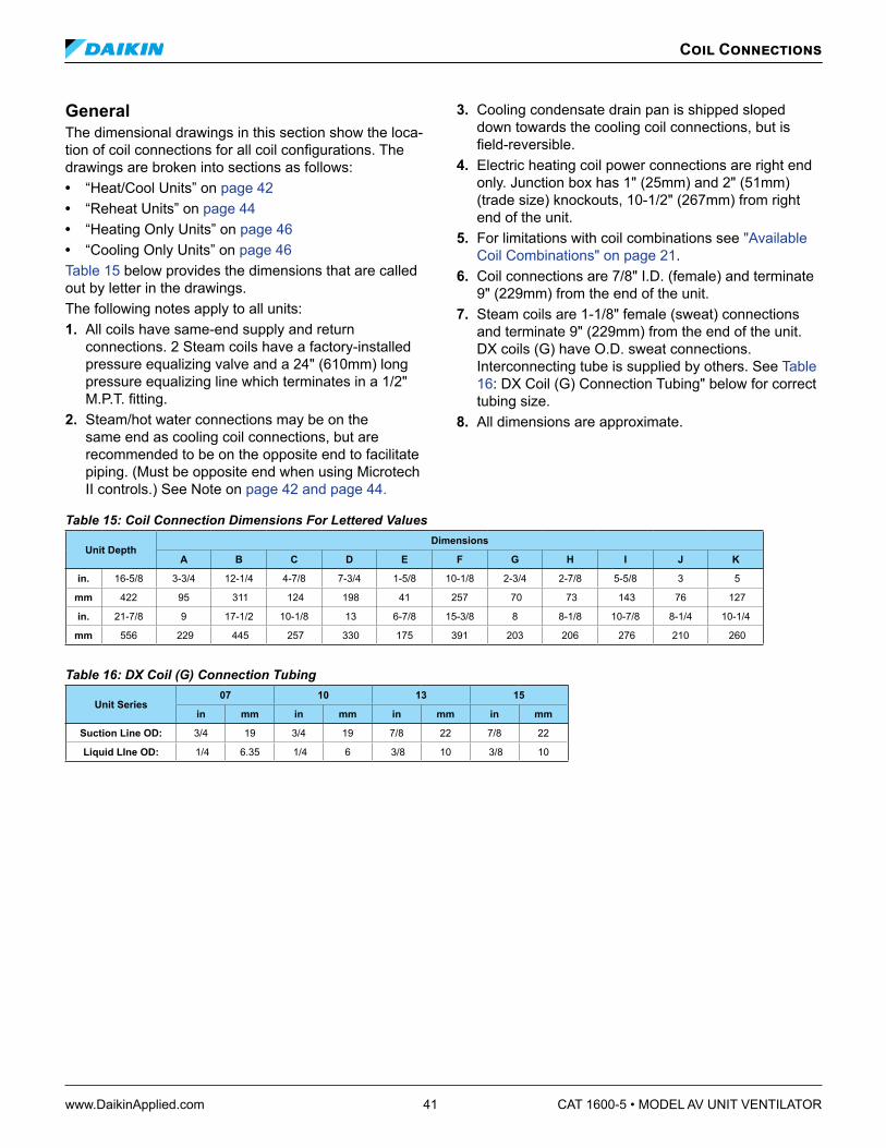
www.DaikinApplied.com 41 CAT 1600-5 • MODEL AV UNIT VENTILATOR
GeneralThe dimensional drawings in this section show the loca-tion of coil connections for all coil configurations. The drawings are broken into sections as follows: • “Heat/Cool Units” on page 42• “Reheat Units” on page 44 • “Heating Only Units” on page 46 • “Cooling Only Units” on page 46 Table 15 below provides the dimensions that are called out by letter in the drawings. The following notes apply to all units: 1. All coils have same-end supply and return
connections. 2 Steam coils have a factory-installed pressure equalizing valve and a 24" (610mm) long pressure equalizing line which terminates in a 1/2" M.P.T. fitting.
2. Steam/hot water connections may be on the same end as cooling coil connections, but are recommended to be on the opposite end to facilitate piping. (Must be opposite end when using Microtech II controls.) See Note on page 42 and page 44.
3. Cooling condensate drain pan is shipped sloped down towards the cooling coil connections, but is field-reversible.
4. Electric heating coil power connections are right end only. Junction box has 1" (25mm) and 2" (51mm) (trade size) knockouts, 10-1/2" (267mm) from right end of the unit.
5. For limitations with coil combinations see "Available Coil Combinations" on page 21.
6. Coil connections are 7/8" I.D. (female) and terminate 9" (229mm) from the end of the unit.
7. Steam coils are 1-1/8" female (sweat) connections and terminate 9" (229mm) from the end of the unit. DX coils (G) have O.D. sweat connections. Interconnecting tube is supplied by others. See Table 16: DX Coil (G) Connection Tubing" below for correct tubing size.
8. All dimensions are approximate.
Coil Connections
Table 15: Coil Connection Dimensions For Lettered Values
Unit DepthDimensions
A B C D E F G H I J K
in. 16-5/8 3-3/4 12-1/4 4-7/8 7-3/4 1-5/8 10-1/8 2-3/4 2-7/8 5-5/8 3 5
mm 422 95 311 124 198 41 257 70 73 143 76 127
in. 21-7/8 9 17-1/2 10-1/8 13 6-7/8 15-3/8 8 8-1/8 10-7/8 8-1/4 10-1/4
mm 556 229 445 257 330 175 391 203 206 276 210 260
Table 16: DX Coil (G) Connection Tubing
Unit Series07 10 13 15
in mm in mm in mm in mm
Suction Line OD: 3/4 19 3/4 19 7/8 22 7/8 22
Liquid LIne OD: 1/4 6.35 1/4 6 3/8 10 3/8 10

CAT 1600-5 • MODEL AV UNIT VENTILATOR 42 www.DaikinApplied.com
Heat/Cool UnitsNote: Numerical codes [#] denote optional stainless steel drain pan (cooling coils).
Chilled Water and Hot Water UnitFigure 50: Chilled Water Cooling Coils V[5], S[6], W[7], Y[8]
Cooling (Left Hand)
16-1/8"(410mm)
E
F
J
11"(279mm)
Air Flow
CW
Vent
PlugR
S HW
Cooling (Right Hand)
16-1/8"(410mm)
E
F
J
11"(279mm)
Air Flow
CW
Vent
PlugR
SHW
Heating (Left Hand)
R
S13-3/4"
(350mm)
A
B
J8-1/2"
(216mm)
Air Flow
Vent
Plug
HWCW
Heating (Right Hand)
RS
13-3/4"(350mm)
A
B
J
Air Flow
Vent
Plug
HWCW
8-1/2"(216mm)
Figure 51: Hot Water Heating Coils 65, 66, 67
Cooling (Left Hand)
16-1/8"(410mm)
E
F
J
11"(279mm)
Air Flow
CW
Vent
PlugR
S HW
Cooling (Right Hand)
16-1/8"(410mm)
E
F
J
11"(279mm)
Air Flow
CW
Vent
PlugR
SHW
Heating (Left Hand)
R
S13-3/4"
(350mm)
A
B
J8-1/2"
(216mm)
Air Flow
Vent
Plug
HWCW
Heating (Right Hand)
RS
13-3/4"(350mm)
A
B
J
Air Flow
Vent
Plug
HWCW
8-1/2"(216mm)
Direct Expansion and Hot Water UnitFigure 52: Direct Expansion Cooling Coils G[9]
Cooling (Left Hand)
DX
Cooling (Right Hand)
J
9-3/4"(248mm)
Air Flow
HW
LL
SL
I
14-1/4"(368mm)
DX
G
Heating (Left Hand)
R
S
13-3/4"(350mm)
A
B
J8-1/2"
(216mm)
Air Flow
Vent
Plug
HWDX
Heating (Right Hand)
RS
13-3/4"(350mm)
A
B
J
Air Flow
Vent
Plug
HWDX
8-1/2"(216mm)
LL = Liquid LineSL = Suction Line
HW
J
9-3/4"(248mm)
Air Flow
LL
SL
I
14-1/4"(368mm)
G
S = SupplyR = Return
Figure 53: Hot Water Heating Coils 65, 66, 67
Cooling (Left Hand)
DX
Cooling (Right Hand)
J
9-3/4"(248mm)
Air Flow
HW
LL
SL
I
14-1/4"(368mm)
DX
G
Heating (Left Hand)
R
S
13-3/4"(350mm)
A
B
J8-1/2"
(216mm)
Air Flow
Vent
Plug
HWDX
Heating (Right Hand)
RS
13-3/4"(350mm)
A
B
J
Air Flow
Vent
Plug
HWDX
8-1/2"(216mm)
LL = Liquid LineSL = Suction Line
HW
J
9-3/4"(248mm)
Air Flow
LL
SL
I
14-1/4"(368mm)
G
S = SupplyR = Return
Direct Expansion and Steam UnitNote: For opposite end drain steam coils (code 78, 79)
Return (R) is 7¼" (184mm) from bottom of unit and (H) 2" (51mm) from the back of unit. Unless otherwise noted, LH and RH connections are the same.
Figure 54: Direct Expansion Cooling Coils G[9]
14-1/4"(368mm)
J
10-1/8"(257mm)
R
S
H
K
Air Flow
J
R
S
H
K
14-1/4"(368mm)
Air Flow
Heating (Left Hand) Heating (Right Hand)
LL
SL
J
D
C
7-1/4"(184mm)
Air Flow
11-3/4"(299mm)
Cooling (Left Hand) Cooling (Right Hand)
LL = Liquid LineSL = Suction Line
DX DX
Steam
Steam
10-1/8"(257mm)
LL
SL
J
D
C
7-1/4"(184mm)
Air Flow
11-3/4"(299mm)
S = SupplyR = Return
Figure 55: Steam Heating Coils 68, 69, 78, 79
14-1/4"(368mm)
J
10-1/8"(257mm)
R
S
H
K
Air Flow
J
R
S
H
K
14-1/4"(368mm)
Air Flow
Heating (Left Hand) Heating (Right Hand)
LL
SL
J
D
C
7-1/4"(184mm)
Air Flow
11-3/4"(299mm)
Cooling (Left Hand) Cooling (Right Hand)
LL = Liquid LineSL = Suction Line
DX DX
Steam
Steam
10-1/8"(257mm)
LL
SL
J
D
C
7-1/4"(184mm)
Air Flow
11-3/4"(299mm)
S = SupplyR = Return
Chilled Water and Steam UnitFigure 56: Chilled Water Cooling Coils V[5], S[6]
14-1/4"(368mm)
10-1/8"(257mm) R
SH
K
Heating (Left Hand) Heating (Right Hand)
Cooling (Left Hand)
RS 13-3/4"
(350mm)
A
B
J8-1/2"
(216mm)
Air Flow
Vent
Plug CW
Cooling (Right Hand)
RS13-3/4"
(350mm)
A
B
J8-1/2"
(216mm)
Air Flow
Vent
PlugCWSteam Steam
J
Air Flow
CW
J
Air Flow
CW
14-1/4"(368mm)
R
SH
K
10-1/8"(257mm)
Figure 57: Steam Heating Coils 68, 69, 78, 79
14-1/4"(368mm)
10-1/8"(257mm) R
SH
K
Heating (Left Hand) Heating (Right Hand)
Cooling (Left Hand)
RS 13-3/4"
(350mm)
A
B
J8-1/2"
(216mm)
Air Flow
Vent
Plug CW
Cooling (Right Hand)
RS13-3/4"
(350mm)
A
B
J8-1/2"
(216mm)
Air Flow
Vent
PlugCWSteam Steam
J
Air Flow
CW
J
Air Flow
CW
14-1/4"(368mm)
R
SH
K
10-1/8"(257mm)
Coil Connections

www.DaikinApplied.com 43 CAT 1600-5 • MODEL AV UNIT VENTILATOR
Chilled Water and Electric Heating CoilsFigure 58: Chilled Water (1st Position) and Electric Heating (Cooling Coils V[5], S[6], W[7]), (Heating Coils 12, 13)
Cooling (Left Hand)
RS 13-3/4"
(350mm)
A
B
J8-1/2"
(216mm)
Air Flow
Vent
Plug CW
Direct Expansion and Electric Heating UnitFigure 59: Direct Expansion (1st Position) and Electric Heating (Cooling Coils G[9]), (Heating Coils 12, 13)
LL = Liquid LineSL = Suction Line
LL
SL
J
D
C
7-1/4"(184mm)
Air Flow
11-3/4"(299mm)
Cooling (Left Hand)
Table 17: Coil Connection Dimensions For Lettered Values1
Unit DepthDimensions
A B C D E F G H I J K
in. 16-5/8 3-3/4 12-1/4 4-7/8 7-3/4 1-5/8 10-1/8 2-3/4 2-7/8 5-5/8 3 5
mm 422 95 311 124 198 41 257 70 73 143 76 127
in. 21-7/8 9 17-1/2 10-1/8 13 6-7/8 15-3/8 8 8-1/8 10-7/8 8-1/4 10-1/4
mm 556 229 445 257 330 175 391 203 206 276 210 260
Table 18: Direct Expansion (DX) Coil G[9] Connection Tubing
Unit Series07 10 13 15
in mm in mm in mm in mm
Suction Line OD: 3/4 19 3/4 19 7/8 22 7/8 22
Liquid LIne OD: 1/4 6.35 1/4 6 3/8 10 3/8 10
Coil Connections

www.DaikinApplied.com 44 CAT 1600-5 • MODEL AV UNIT VENTILATOR
Coil Connections
Reheat UnitsChilled Water and Hot Water UnitNote: Numerical codes [#] denote optional stainless steel
drain pan (cooling coils).
Figure 60: Chilled Water Coils V[5], S[6], W[7], Y[8]
Chilled Water (Left Hand)
RS 13-3/4"
(350mm)
A
B
J8-1/2"
(216mm)
Air Flow
Vent
Plug
HWCW
Chilled Water (Right Hand)
RS13-3/4"
(350mm)
A
B
J
Air Flow
Vent
Plug
HWCW
8-1/2"(216mm)
Hot Water (Left Hand)
16-1/8"(410mm)
E
F
J
11"(279mm)
Air Flow
CW
Vent
Plug RS
HW
Hot Water (Right Hand)
16-1/8"(410mm)
E
F
J
11"(279mm)
Air Flow
CW
Vent
PlugRSHW
Figure 61: Hot Water Heating Coils 65, 66, 67
Chilled Water (Left Hand)
RS 13-3/4"
(350mm)
A
B
J8-1/2"
(216mm)
Air Flow
Vent
Plug
HWCW
Chilled Water (Right Hand)
RS13-3/4"
(350mm)
A
B
J
Air Flow
Vent
Plug
HWCW
8-1/2"(216mm)
Hot Water (Left Hand)
16-1/8"(410mm)
E
F
J
11"(279mm)
Air Flow
CW
Vent
Plug RS
HW
Hot Water (Right Hand)
16-1/8"(410mm)
E
F
J
11"(279mm)
Air Flow
CW
Vent
PlugRSHW
Direct Expansion and Hot Water UnitFigure 62: Direct Expansion Cooling Coils G[9]
S = SupplyR = Return
LL
SL
J
D
C
7-1/4"(184mm)
Air Flow
11-3/4"(299mm)
Cooling (Right Hand)
LL = Liquid LineSL = Suction Line
HWLL
SL
J
D
C
7-1/4"(184mm)
Air Flow
11-3/4"(299mm)
Cooling (Left Hand)
HW
Hot Water (Left Hand)
16-1/8"(410mm)
E
F
J
11"(279mm)
Air Flow
DX
Vent
Plug RS
HW
Hot Water (Right Hand)
16-1/8"(410mm)
E
F
J
11"(279mm)
Air Flow
DX
Vent
PlugRSHW
Figure 63: Hot Water Heating Coils 65, 66, 67
S = SupplyR = Return
LL
SL
J
D
C
7-1/4"(184mm)
Air Flow
11-3/4"(299mm)
Cooling (Right Hand)
LL = Liquid LineSL = Suction Line
HWLL
SL
J
D
C
7-1/4"(184mm)
Air Flow
11-3/4"(299mm)
Cooling (Left Hand)
HW
Hot Water (Left Hand)
16-1/8"(410mm)
E
F
J
11"(279mm)
Air Flow
DX
Vent
Plug RS
HW
Hot Water (Right Hand)
16-1/8"(410mm)
E
F
J
11"(279mm)
Air Flow
DX
Vent
PlugRSHW
Direct Expansion and Steam UnitNote: For opposite end drain steam coils (code 78, 79)
Return (R) is 7¼" (184mm) from bottom of unit and (H) 2" (51mm) from the back of unit. Unless otherwise noted, LH and RH connections are the same.
Figure 64: Direct Expansion Cooling Coils G[9]
14-1/4"(368mm)
J
10-1/8"(257mm)
R
S
H
K
Air Flow
J
R
S
H
K
14-1/4"(368mm)
Air Flow
Heating (Left Hand) Heating (Right Hand)
LL
SL
J
D
C
7-1/4"(184mm)
Air Flow
11-3/4"(299mm)
Cooling (Right Hand)
LL = Liquid LineSL = Suction Line
DX DXSteam
10-1/8"(257mm)
LL
SL
J
D
C
7-1/4"(184mm)
Air Flow
11-3/4"(299mm)
Cooling (Left Hand)
Steam
S = SupplyR = Return
Figure 65: Steam Heating Coils 68, 69, 78, 79
14-1/4"(368mm)
J
10-1/8"(257mm)
R
S
H
K
Air Flow
J
R
S
H
K
14-1/4"(368mm)
Air Flow
Heating (Left Hand) Heating (Right Hand)
LL
SL
J
D
C
7-1/4"(184mm)
Air Flow
11-3/4"(299mm)
Cooling (Right Hand)
LL = Liquid LineSL = Suction Line
DX DXSteam
10-1/8"(257mm)
LL
SL
J
D
C
7-1/4"(184mm)
Air Flow
11-3/4"(299mm)
Cooling (Left Hand)
Steam
S = SupplyR = Return
Chilled Water and Steam UnitFigure 66: Chilled Water Coils V[5], S[6]
14-1/4"(368mm)
10-1/8"(257mm) R
SH
K
Heating (Left Hand) Heating (Right Hand)
Chilled Water (Left Hand)
RS 13-3/4"
(350mm)
A
B
J8-1/2"
(216mm)
Air Flow
Vent
Plug CW
Chilled Water (Right Hand)
RS13-3/4"
(350mm)
A
B
J8-1/2"
(216mm)
Air Flow
Vent
PlugCWSteam Steam
J
Air Flow
CW
J
Air Flow
CW
14-1/4"(368mm)
R
SH
K
10-1/8"(257mm)
Figure 67: Steam Heating Coils 68, 69, 78, 79
14-1/4"(368mm)
10-1/8"(257mm) R
SH
K
Heating (Left Hand) Heating (Right Hand)
Chilled Water (Left Hand)
RS 13-3/4"
(350mm)
A
B
J8-1/2"
(216mm)
Air Flow
Vent
Plug CW
Chilled Water (Right Hand)
RS13-3/4"
(350mm)
A
B
J8-1/2"
(216mm)
Air Flow
Vent
PlugCWSteam Steam
J
Air Flow
CW
J
Air Flow
CW
14-1/4"(368mm)
R
SH
K
10-1/8"(257mm)

www.DaikinApplied.com 45 CAT 1600-5 • MODEL AV UNIT VENTILATOR
Chilled Water and Electric Heating CoilsFigure 68: Chilled Water (1st Position) and Electric Heating (Cooling Coils V[5], S[6], W[7]), (Heating Coils 12, 13)
Cooling (Left Hand)
RS 13-3/4"
(350mm)
A
B
J8-1/2"
(216mm)
Air Flow
Vent
Plug CW
Direct Expansion and Electric Heating UnitFigure 69: Direct Expansion (1st Position) and Electric Heating (Cooling Coils G[9]), (Heating Coils 12, 13)
LL = Liquid LineSL = Suction Line
LL
SL
J
D
C
7-1/4"(184mm)
Air Flow
11-3/4"(299mm)
Cooling (Left Hand)
Table 19: Coil Connection Dimensions For Lettered Values1
Unit DepthDimensions
A B C D E F G H I J K
in. 16-5/8 3-3/4 12-1/4 4-7/8 7-3/4 1-5/8 10-1/8 2-3/4 2-7/8 5-5/8 3 5
mm 422 95 311 124 198 41 257 70 73 143 76 127
in. 21-7/8 9 17-1/2 10-1/8 13 6-7/8 15-3/8 8 8-1/8 10-7/8 8-1/4 10-1/4
mm 556 229 445 257 330 175 391 203 206 276 210 260
Table 20: Direct Expansion (DX) Coil G[9] Connection Tubing
Unit Series07 10 13 15
in mm in mm in mm in mm
Suction Line OD: 3/4 19 3/4 19 7/8 22 7/8 22
Liquid LIne OD: 1/4 6.35 1/4 6 3/8 10 3/8 10
Coil Connections

Coil Connections
CAT 1600-5 • MODEL AV UNIT VENTILATOR 46 www.DaikinApplied.com
Heating Only UnitsFigure 70: Hot Water Only Unit (Coils 65, 66, 67)Note: This arrangement available on AVV and AVS units only.
R
S
J
A
B B
8-1/2"(216mm)
13-3/4"(349mm)
J
A
13-3/4"(349mm)
8-1/2"(216mm)
Air Flow
Left Hand Right Hand
Air Flow
R
S
S = SupplyR = Return
Figure 71: Steam Heating Only Unit (Coils 68, 69, 78, 79)Note: This arrangement available on AVV and AVS units only.
RS
16-1/8"(410mm)
11"(279mm)
Air Flow
R
S
16-1/8"(410mm)
J11"
(279mm)
K
H
Air Flow
Left Hand Right Hand
J
K
H
S = SupplyR = Return
Figure 72: Electric Heating Only Unit (Coils 12, 13)Note: This arrangement available on AVV units only.
J
Air Flow
Right Hand
Cooling Only UnitsFigure 73:Chilled Water Only Unit (Coils V, S, W)Note: This arrangement available on AVV and AVS units only.
RS
J
A
B B
8-1/2"(216mm)
13-3/4"(349mm)
J
A
13-3/4"(349mm)
8-1/2"(216mm)
Air Flow
Right HandLeft Hand
R
S
S = SupplyR = Return
Figure 74: Direct Expansion Cooling Only Unit (Coils G)Note: This arrangement available on AVV units only.
LL
SL
J
D
C
7-1/4"(184mm)
Air Flow
11-3/4"(299mm)
Air Flow
Cooling (Left Hand) Cooling (Right Hand)
LL = Liquid LineSL = Suction Line
LL
SL
J
D
C
7-1/4"(184mm)
11-3/4"(299mm)
Condensate Drain LocationsFigure 75: Condensate Drain
7/8"(22 mm)O.D. Drain
7/8"(22 mm)O.D. DrainCondensate
Left Hand Right Hand
Drain
11"(279 mm)
11"(279 mm)
Front View of End Compartment(Without End Panels)
4-3/4"(121 mm)
Figure 76: Condensate Drain and DX Coil Connections
7/8"(22 mm)O.D. Drain
11"(279 mm)
11"(279 mm)
Front View of End Compartment(Without End Panels)
4-3/4"(121 mm)
SL
SL
LL LL
LL = Liquid LineSL = Suction Line
5-1/4" (133 mm)
1-1/2" (38 mm)
5-1/4" (133 mm)
1-1/2" (38 mm)
TX Valve
TX Valve
Left Hand Right Hand

www.DaikinApplied.com 47 CAT 1600-5 • MODEL AV UNIT VENTILATOR
End Panels
End Panel – DimensionsTable 21: 1" (25 mm) End Panel Dimensions
16-5/8" (422mm) Deep End Panel
21-7/8" (556mm) Deep End Panel
28" (711mm) Deep End Panel
Top View16 5/8"
(422mm) 1"(25mm)
21 7/8"(556mm) 1"
(25mm)
28"(711mm) 1"
(25mm)
End ViewWith No Cut-out
27 7/8"(708mm)
27 7/8"(708mm)
27 7/8"(708mm)
End View With 2-1/2" x 7"
(64mm x 178mm)Cut-out
27 7/8"(708mm)
7"(178mm)
2 1/2"(64mm)
1"(25mm)
27 7/8"(708mm)
7"(178mm)
2 1/2"(64mm)
1"(25mm)
End View With 4" x 18"
(102mm x 457mm)Cut-out
27 7/8"(708mm)
18"(457mm)
4"(102mm)
1"(25mm)
27 7/8"(708mm)
18"(457mm)
4"(102mm)
1"(25mm)
End View With 4" x 22"
(102mm x 559mm)Cut-out
27 7/8"(708mm)
22"(559mm)
4"(102mm)
1"(25mm)
27 7/8"(708mm)
22"(559mm)
4"(102mm)
1"(25mm)
27 7/8"(708mm)
22"(559mm)
4"(102mm)
1"(25mm)
End View With 2" x 5-1/4"
(51mm x 133mm)Step Down
27 7/8"(708mm)
2"(51mm)
5 1/4"(133mm)
Table 22: 6" (152 mm) End Panel Dimensions16-5/8" (422mm) Deep End Panel
21-7/8" (556mm) Deep End Panel
28" (711mm) Deep End Panel
Top View
16 5/8"(422mm) 6"
(152mm)
21 7/8"(556mm) 6"
(152mm)
28"(711mm) 6"
(152mm)
End ViewWith No Cut-out
27 7/8"(708mm)
27 7/8"(708mm)
27 7/8"(708mm)

CAT 1600-5 • MODEL AV UNIT VENTILATOR 48 www.DaikinApplied.com
Face & Bypass End of Cycle ValvesFigure 77: 2-Way EOC Valve
X, Y, Z DimensionsConnection Cv X Y Z
3/4" (19mm) FNPT 7.5 11-1/16"
(43mm)1-1/16" (23mm)
3-5/8" (92mm)
1" (25mm) 8.0 1-7/8" (47mm) 1" (25mm) 3-11/16"
(94mm)
Figure 78: 3-Way EOC Valve Modulating Valves
Connection Cv
3/4" (19mm) FNPT 5.0
Table 23: Actuator SpecificationsControl 2 Position
Electrical 24 VAC, 50/60 Hz
Stroke Power Stroke 9 to 11 secondsSpring return 4 to 5 seconds
Ambient 32°F to 125°F (0°C to 52°C)
Table 24: F&BP Valve Body Specifications2-Way Valve 3-Way Valve
Connections 3/4" FNPT, 1" FNPT 3/4" FNPT
Static Pressure 300 psi (2100 kPa) 300 psi (2100 kPa)
Close-Off Pressure 13 & 15 psi (90 & 103 kPa) 13 psi (90 kPa)
Temperature 32°F to 200°F (0°C to 93°C)
32°F to 200°F (0°C to 93°C)
Modulating ValvesFigure 79: 2-Way Modulating Valve
4-3/32"(104mm)
3-5/32"(80mm)
6-13/16"(173mm)
A
B
C
3-19/32"(91mm)11/32"
(8mm)
Figure 80: 3-Way Modulating Valve
4-3/32"(104mm)3-5/32"
(80mm)
6-13/16"(173mm)
AB
C
3-15/16"(100mm)11/32"
(8mm)
Valves

www.DaikinApplied.com 49 CAT 1600-5 • MODEL AV UNIT VENTILATOR
Table 25: 2-Way and 3-Way Modulating Valve DimensionsValve Size in(DN)
A BCN.O./N.C.
3-Way2-Way N.O.
2-Way N.C. 3-Way
1/2 (DN15) 3 (76) 13/16 (21) 1-9/16 (39) 1-13/16 (46) 8 (203)
3/4 (DN20) 3-7/32 (81) 15/16 (24) 1-5/8 (41) 2-1/8 (54) 8 (203)
1 (DN25) 4-1/8 (119) 1-5/32 (29) 1-3/4 (44) 2-9/16 (65) 9-7/32 (234)
1-1/4 (DN32) 4-23/32 (119) 1-11/32 (34) 2 (51) 2-25/32 (70) 9-7/32 (234)
Table 26: Actuator Specifications
Control Floating Point Modulating
Electrical 20 to 30 VAC at 50/60 Hz or 24 VDC ± 10%
Transformer 12 VA (class 2 power source)
Stroke 29/32 in. (23mm) max. 76 seconds
Operating Temp 35 to 250°F (2 to 121°C); 15 psig (103 kPa)saturated steam
Table 27: Modulating Valve Body Specifications
Connections Static
Pressure
Water400 psig (2.756 PA) up to 150°F; (66°C)decreasing to 365 psig; (2,515 kPa) at
248°F (120°C)
Steam 38 psig (262 kPa) Saturated steam at 284°F
Fluid Temperatures 35 to 250°F (2 to 121°C); 15 psig (103kPa) saturated steam
Wall Intake Louvers & GrillesLouvers are available in both horizontal and vertical blade configurations:• Horizontal blade construction turns the incoming air
to keep moisture from entering. Bottom weep holes drain moisture to the outside.
• Vertical-blade construction provides positive water impingement and entrapment. The bottom lip drains moisture to the outside.
Louvers can be supplied with or without flanges:• Flanged louvers are typically used for a panel wall finish.• Unflanged louvers are typically used for recessing
into a masonry wall.
A half-inch-square mesh bird screen located on the leav-ing air side of the louver prevents birds and other small animals from entering. The screen’s strong aluminum mesh is designed to minimize air pressure drops, unlike expanded metal mesh.Table 28: Louver Specifications
Unit
Nominal Air Flow
Louver Dimensisons ± 1/16" (± 2mm)
Recommended Wall Opening
CFM L/s L = Length Height Length Height
07 750 354 36"(914mm
10-3/8"(264mm)
36-1/4"(921mm)
10-1/2"(267mm)
10 1000 472 48"(1219mm)
48-1/4"(1225mm)
13 1250 590 60"(1524mm)
60-1/4"(1530mm
15 1500 708 72"(1829mm)
72-1/4"(1835mm)
Figure 81: Louver with Flange (Horizontal Blades Shown)
Grille (Optional)
Louver Weep Holes in this Area
Bird Screen on Inside
10.375" 254mm
1" 25mm
12.375"314mm
L
1" 25mm
Figure 61: Louver without Flange (Vertical Blades Shown)
Grille (Optional)
Louver Weep Holes in this Area
Bird Screen on Inside
L2.14" 51mm
10.375"254mm
Wall Louvers

www.DaikinApplied.com 50 CAT 1600-5 • MODEL AV UNIT VENTILATOR
VentiMatic Shutter
VentiMatic Shutter AssemblyNotes: 1. Horizontal blade louver shown. Vertical blade louver also available with VentiMatic shutter. 2. Optional exterior grille matches unit ventilator louver in material and design. Mounted in wall louver. 3. Optional interior grille mounting hardware is not included. 4.Louverleavessealagainstplatetopreventairinfiltration.
Figure 82: VentiMatic Shutter Assembly with Optional Grille
Louver
Two Shutter Assemblies Mounted on One Louver
Center Cover
Aluminum Exterior Grille (optional)
Aluminum Exterior Grille (optional)
Aluminum Louver
Aluminum Louver
Steel Interior Grille (optional)
Steel Interior Grille (optional)
Baffle PlateB
(See table)
B
(See table)
C
(See table)
A
(See table)
Table 29: Recommended Wall Openings and Max Air Capacities for VentiMatic Shutter Assembly
Exterior GrilleWidth A
LouverWidth B
Interior GrilleWidth C
Recommended Wall OpeningFor Louver
Max Number of VentiMaticShutters To Mount On
Standard Louver
VentiMaticShutter(s) MaxAir Capacity
inches mm inches mm inches mmLength Width 24" (610mm)
Shutter36" (914mm)
Shutter CFM L/sinches mm inches mm
23-3/4 603 24 610 27 686 24-1/4 616
10-1/2 267
1 0 500 236
36-3/4 933 36 914 39 991 36-1/4 921 0 1 750 354
47-3/4 1213 48 1219 51 1295 48-1/4 1225 2 0 1000 472
59-3/4 1518 60 1524 63 1600 60-1/4 1530 1 1 1250 590
71-3/4 1822 72 1829 75 1905 72-1/4 1835 0 2 1500 708

CAT 1600-5 • MODEL AV UNIT VENTILATOR 51 www.DaikinApplied.com
Quick Selection ProcedureThe following procedure will provide you with a rough determination of unit capacity for cooling and/or heating based on the number of coil rows. Use capacity tables for final selection. Consult your local Daikin represen-tative for details on the computer selection programs Daikin Applied provides for this purpose.
Step 1: Determine Design Conditions Determine design indoor and outdoor air temperatures in accordance with established engineering practices, as outlined in the ASHRAE Guide or other authoritative source. Indoor temperatures of 80°F dry bulb, 67°F wet bulb for summer and 70°F dry bulb for winter usually are acceptable for design or peak load conditions, even though the expected operating conditions of the system may be somewhat different.Table 30: Chilled Water Cooling Capacity BTUH
80/67°F Entering Air Temperature; 45°F Entering Water Temperature; 10°F Water Temperature Rise
Rows 750 cfm 1000 cfm 1250 cfm 1500 cfm
2 17,900 23,600 31,500 38,800
3 21,700 33,300 41,100 51,200
4 27,800 35,600 43,400 56,700
5 27,900 32,200 45,400 54,500
Table 31: Hot Water Heating Capacity BTUH60°F Entering Air Temperature; 160°F Entering Water Tem-
perature; 6 Gpm Water Flow
Rows 750 cfm 1000 cfm 1250 cfm 1500 cfm
1 37,000 49,500 57,000 66,000
2 48,300 62,000 74,100 97,200
3 56,800 72,000 84,500 97,500
4 62,500 81,000 95,000 110,000
Table 32: Steam Heating Capacity BTUH0°F Entering Air Temperature; 2 PSI Steam at 218.5°F
750 cfm 1000 cfm 1250 cfm 1500 cfm
Std Cap Hi Cap Std
Cap Hi Cap Std Cap Hi Cap Std
Cap Hi Cap
50,300 66,500 75,200 89,900 89,000 112,500 111,500 128,500
Table 33: Electric Heating Capacity BTUH
Voltage750 cfm 1000 cfm 1250 cfm 1500 cfm
Low High Low High Low High Low High230-1, 230-3, 265-1, 460-3 18,835 37,670 25,113 50,227 31,392 62,783 37,670 75,340
208-1, 208-3 20,473 40,946 27,297 54,594 34,121 68,243 40,946 81,891
Step 2: Determine Heating and Cooling Loads Calculate design winter heating losses and summer cooling loads in accordance with the procedures outlined by the ASHRAE Guide or other authoritative source.
Perhaps the greatest consideration in calculating de-sign loads is solar heat gain. August solar heat values might be used for summer cooling loads, but should not be used for ventilation air or “natural cooling” capacity calculations; since these cooling loads reach their maxi-mum in the spring and autumn months. The natural cool-ing capacity is usually calculated for 55° or 60°F outdoor air temperature (Table 34).Table 34: Outdoor Air Ventilation Sensible Cooling Capacites Based On 75°F Room Temperature
Unit Size Nominal CFMOutdoor Air Temperature
55°F 60°F
07 750 16.3 MBH 12.2 MBH
10 1000 21.7 MBH 16.3 MBH
13 1250 27.1 MBH 20.3 MBH
15 1500 32.6 MBH 24.4 MBH
Step 3: Determine Air Quantity Required Air quantity for heating applications is determined from circulation of a definite number of room air volumes per hour. Table 35 gives the recommended number of room air changes per hour. Table 35: Recommended Room Air Changes Per Hour
Type of Space Recommended Number of Room Air Changes Per Hour
Classrooms, Offices 6 to 9
Laboratories, Shops 6 to 8
Cafeterias,& Kitchens 4-1/2 to 7
For rooms facing east, south or west, the higher values shown in the table should be used so adequate ventila-tion cooling will be available to prevent overheating dur-ing mild sunny weather. The following equation is helpful to determine the CFM air delivery for any given rate of circulation: Equation 3: CFM For Given Rate Of Circulation Room Volume (cu ft) × Room Changes per Hour
=CFM 60 In mechanical cooling applications, the total air quantity may be determined or verified by use of the sensible cooling load equation: Equation 4: CFM Based On Sensible Cooling Load
CFM = Q sensible (space)
1.086 × TD
Performance and Selection

www.DaikinApplied.com 52 CAT 1600-5 • MODEL AV UNIT VENTILATOR
Q sensible is the maximum sensible room load and T.D. is the temperature difference between the room design dry bulb temperature and the final or leaving-air dry bulb temperature. For these calculations, a T.D. of 20°F is usually assumed to be desirable to avoid delivering air too cold for comfort. This figure may be varied one or two degrees for reasons of practicality. Note: The sensible load used in the preceding equation is
the space load and excludes the ventilation load. Most areas have ventilation codes which govern the amount of ventilation air required for school applications. For other than school applications or areas not having codes, the ASHRAE Guide may be used for authoritative recommendations and discussion of the relation be-tween odor control and outdoor air quantities. The minimum outdoor air quantity recommended by ASHRAE for K-12 classrooms is 10 CFM per person plus 0.12 cfm/ft2. Lower percent minimum outdoor air settings are more economical. In the interest of econo-my, it may be desirable to use lower percent minimums if there are no ventilation codes.
Step 4: Select Unit Size The unit should be selected to meet or exceed the CFM delivery requirement previously determined. All model types are available with nominal capacities of 750, 1000, 1250 and 1500 CFM. Heating Capacity Unit heating capacity should be selected to equal or slightly exceed the computed room heat loss. For units installed for 100% recirculation, it is good practice to in-crease the heating capacity by 15% to aid in quick room warm-up. This allowance is unnecessary for units deliv-ering a minimum outdoor air of 20% or more, since the outdoor air damper remains closed until the room is up to temperature. The heat normally expended in heating the minimum-percent outdoor air up to room temperature is available for quick warm-up purposes. The heating required to warm the outdoor ventilating air up to room temperature must also be calculated. The To-tal Capacity should be used in sizing, piping, boilers, etc. Cooling Capacity Unit cooling capacity should be selected to equal or slightly exceed the sum of computed room sensible and latent
Step 5: Freeze ProtectionConstant pump operation is required whenever the outdoor air temperature is below 35°F. This will assist in providing protection against freeze up of the system water piping and coils. To reduce the possibility of water coil freeze up on valve-controlled units, the valve must be selected properly to provide adequate water flow. See "Modulating Valve Sizing & Piping" on page 101. One of the steps below should be followed.
Chilled WaterCarry out one of the following steps to help protect against freezing:• Drain the chilled water system during cold weather.• Open the chilled water coil valves and operate the
chilled water circulating pump any time the outside air temperature is below 35°F.
• Use antifreeze in the system.Hot WaterCarry out one of the following steps to help protect against freezing:• Use antifreeze in the system.• Open the hot water coil valve and close the outdoor
air damper whenever a freezing condition is sensed at the coil. Freezestat furnished by Automatic Temperature Control supplier.
Step 6: Units With AntifreezeIf ethylene glycol or propylene glycol is used, its effect upon heating and cooling capacities and its effect on water pressure drops through the coil and piping system must be considered, as follows:1. Divide the heating and/or cooling loads determined
in Step 2 by the applicable capacity correction factor shown in Table 36 and Table 37 below to arrive at the calculated unit capacity required to take care of the capacity reduction caused by the glycol solution.
Table 36: Capacity Correction Factors for Ethylene GlycolEthylene Glycol% Weight 20% 30% 40%
Chilled Water 0.92 0.84 0.75
Hot Water 0.94 0.90 0.84
Table 37: Capacity Correction Factors for Propylene GlycolPropylene Glycol% Weight 20% 30% 40%
Chilled Water 0.86 0.73 0.62
Hot Water 0.98 0.96 0.92
2. Determine the GPM required by entering the appropriate chilled water cooling capacity table or hot water capacity chart using the calculated unit capacity.
3. Determine the water pressure drop by multiplying the water pressure drop for the GPM determined above by the applicable pressure drop correction factor shown in Table 38 and Table 39 below.
Table 38: Pressue Drop Correction Factors for Ethylene Glycol
Ethylene Glycol% Weight 20% 30% 40%
Chilled Water 1.15 1.22 1.34
Hot Water 1.08 1.11 1.19
Table 39: Pressure Drop Correction Factors for Propylene Glycol
Propylene Glycol% Weight 20% 30% 40%
Chilled Water 1.24 1.27 1.35
Hot Water 1.07 1.11 1.15
Performance and Selection

CAT 1600-5 • MODEL AV UNIT VENTILATOR 53 www.DaikinApplied.com
Chilled Water Selection ExampleStep 1: Determine Design ConditionsAssume the following design indoor and outdoor air tem-peratures are given:• Outdoor design temperature = 96°F DB / 74°F WB• Room design temperature = 76°F DB / 65°F WB
Step 2: Determine Cooling LoadsAssume the following cooling loads are given:• Minimum total capacity (TC) = 43.4 MBH• Minimum sensible capacity (SC) = 28.3 MBH• Minimum outdoor air = 20%• Room volume = 9,000 cubic feet• Desired number of air changes per hour = 8• Supply water temperature = 45°F EWT
Step 3: Determine Air Quantity RequiredEquation 3 on page 56 indicates that to obtain eight room volumes per hour, a unit capable of delivering 1200 CFM standard air must be used, as follows:
CFM = (Room Volume Ft3) × (Room Changes per Hour)
80
CFM = 9000 × 8
= 1200 60
This indicates that an S13 Unit Ventilator should be usedwhich delivers 1250 CFM.
Step 4: Select Unit SizeDetermine the water flow (GPM), water temperature rise and the coil pressure drop as follows:
Determine Entering Dry Bulb TemperatureThe entering dry bulb (EDB) temperature is calculated using the following formula: EDB = Room DB ×
%RA + Outdoor DB ×
%OA 100 100
EDB = 76(0.8) + (96)(0.2) = 80°F
Determine Entering Wet Bulb TemperatureThe entering wet bulb (EWB) temperature is determined by calculating the Enthalpy (H) at saturation, then look-ing up the corresponding EWB (Table 40 on page 54). Enthalpy (H) is calculated as follows:
Enthalpy (H) = Room Enthalpy × %RA
+ Outdoor Enthalpy ˣ %OA
100 100
Enthalpy (H) = 30.06 (0.8) + 37.66 (0.2) = 31.58 btu/lb
Referring to Table 40 on page 54, EWB for 31.58 btu/lb = 67°FLook Up CapacitiesLook up the Chilled Water Cooling Coil Capacity Tablefor our calculated values and cooling loads (ED-18507):• Unit size: 1250 cfm• Entering dry bulb (EDB) = 80• Entering wet bulb (EWB) = 67°F• Supply water temperature (EWT) = 45°FUnder these conditions, the 4-row coil produces:• 43.4 MBH (TC)• 28.3 MBH (SC)• 8.8 GPM• 6.7 ft. H20 (WPD)• 10°F (TR)Leaving air temperatures dry bulb °F (LDB) and wet bulb°F (LWB) may be calculated as follows:
LDB = EDB - SC(Btuh)
= 80 - 28300
= 59.1°F
CFM × 1.085 1250 × 1.085
LWBH = EWBH - TC(Btuh)
= 31.62 - 43400
= 23.9
CFM × 4.5 1250 × 4.5
From Table 40 on page 54:LWB at 23.9 H = 56.1°F.Note: Interpolation within each table and between sets of
tables for each unit series is permissible.For conditions of coil performance beyond the scope of the catalog selection procedures, Daikin offers com-puter selection programs for chilled water, hot water and steam coils. Consult your local Daikin representative for details.
Performance and Selection

www.DaikinApplied.com 54 CAT 1600-5 • MODEL AV UNIT VENTILATOR
Performance and Selection
Table 40: Enthalpy (H) at Saturation But Per Pound of Dry Air
Wet Bulb Temp. °F
Tenths of A Degree
0 0.1 0.2 0.3 0.4 0.5 0.6 0.7 0.8 0.9
50 20.3 20.36 20.41 20.47 20.52 20.58 20.64 20.69 20.75 20.8
51 20.86 20.92 20.97 21.03 21.09 21.15 21.2 21.26 21.32 21.38
52 21.44 21.5 21.56 21.62 21.67 21.73 21.79 21.85 21.91 21.97
53 22.02 22.08 22.14 22.2 22.26 22.32 22.38 22.44 22.5 22.56
54 22.62 22.68 22.74 22.8 22.86 22.92 22.98 23.04 23.1 23.16
55 23.22 23.28 23.34 23.41 23.47 23.53 23.59 23.65 23.72 23.78
56 23.84 23.9 23.97 24.03 24.1 24.16 24.22 24.29 24.35 24.42
57 24.48 24.54 24.61 24.67 24.74 24.8 24.86 24.93 24.99 25.06
58 25.12 25.19 25.25 25.32 25.38 25.45 25.52 25.58 26.65 25.71
59 25.78 25.85 25.92 25.98 26.05 26.12 26.19 26.26 26.32 26.39
60 26.46 26.53 26.6 26.67 26.74 26.81 26.87 26.94 27.01 27.08
61 27.15 27.22 27.29 27.36 27.43 27.5 27.57 27.64 27.71 27.78
62 27.85 27.92 27.99 28.07 28.14 28.21 28.28 28.35 28.43 28.5
63 28.57 28.64 28.72 28.79 28.87 28.94 29.01 29.09 29.16 29.24
64 29.31 29.39 29.46 29.54 29.61 29.69 29.76 29.84 29.91 29.99
65 30.06 30.14 30.21 30.29 30.37 30.45 30.52 30.6 30.68 30.78
66 30.83 30.91 30.99 31.07 31.15 31.23 31.3 31.38 31.46 31.54
67 31.62 31.7 31.78 31.86 31.94 32.02 32.1 32.18 32.26 32.34
68 32.42 32.5 32.59 32.67 32.75 32.84 32.92 33 33.08 33.17
69 33.25 33.33 33.42 33.5 33.59 33.67 33.75 33.84 33.92 34.01
70 34.09 34.18 34.26 34.35 34.43 34.52 34.61 34.69 34.78 34.86
71 34.95 35.04 35.13 35.21 35.3 35.39 35.48 35.57 35.65 35.74
72 35.83 35.92 36.01 36.1 36.19 36.29 36.38 36.47 36.56 36.65
73 36.74 36.83 36.92 37.02 37.11 37.2 37.29 37.38 37.48 37.57
74 37.66 37.76 37.85 37.95 38.04 38.14 38.23 38.33 38.42 38.52
75 38.61 38.71 38.8 38.9 38.99 39.09 39.19 39.28 39.38 39.47
76 39.57 39.67 39.77 39.87 39.97 40.07 40.17 40.27 40.37 40.47
77 40.57 40.67 40.77 40.87 40.97 41.08 41.18 41.28 41.38 41.48
78 41.58 41.68 41.79 41.89 42 42.1 42.2 42.31 42.41 42.52
79 42.62 42.73 42.83 42.94 43.05 43.16 43.26 43.37 43.48 43.58
80 43.69 43.8 43.91 44.02 44.13 44.24 44.34 44.45 44.56 44.67
81 44.78 44.89 45 45.12 45.23 45.34 45.45 45.56 45.68 45.79
82 45.9 46.01 46.13 46.24 46.36 46.47 46.58 46.7 46.81 46.93
83 47.04 47.16 47.28 47.39 47.51 47.63 47.75 47.87 47.98 48.1
84 48.22 48.34 48.46 48.58 48.7 48.83 48.95 49.07 49.19 49.31
85 49.43 49.55 49.68 49.8 49.92 50.05 50.17 50.29 50.41 50.54
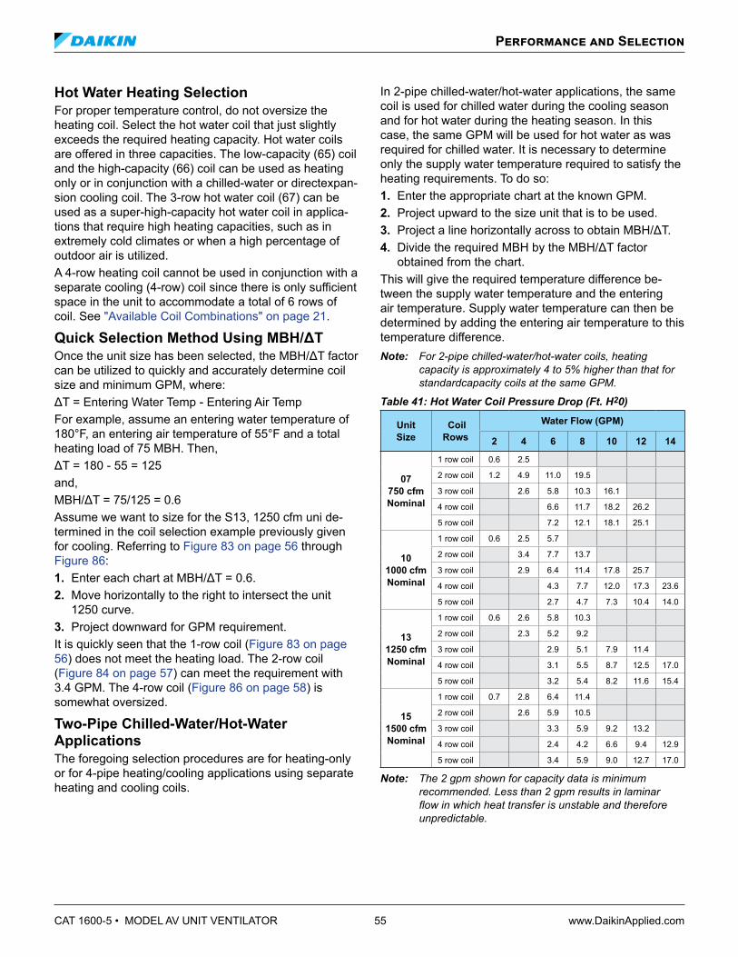
CAT 1600-5 • MODEL AV UNIT VENTILATOR 55 www.DaikinApplied.com
Hot Water Heating SelectionFor proper temperature control, do not oversize the heating coil. Select the hot water coil that just slightly exceeds the required heating capacity. Hot water coils are offered in three capacities. The low-capacity (65) coil and the high-capacity (66) coil can be used as heating only or in conjunction with a chilled-water or directexpan-sion cooling coil. The 3-row hot water coil (67) can be used as a super-high-capacity hot water coil in applica-tions that require high heating capacities, such as in extremely cold climates or when a high percentage of outdoor air is utilized.A 4-row heating coil cannot be used in conjunction with a separate cooling (4-row) coil since there is only sufficient space in the unit to accommodate a total of 6 rows of coil. See "Available Coil Combinations" on page 21.
Quick Selection Method Using MBH/ΔTOnce the unit size has been selected, the MBH/ΔT factor can be utilized to quickly and accurately determine coil size and minimum GPM, where:ΔT = Entering Water Temp - Entering Air TempFor example, assume an entering water temperature of 180°F, an entering air temperature of 55°F and a total heating load of 75 MBH. Then,ΔT = 180 - 55 = 125and,MBH/ΔT = 75/125 = 0.6Assume we want to size for the S13, 1250 cfm uni de-termined in the coil selection example previously given for cooling. Referring to Figure 83 on page 56 through Figure 86:1. Enter each chart at MBH/ΔT = 0.6.2. Move horizontally to the right to intersect the unit
1250 curve.3. Project downward for GPM requirement.It is quickly seen that the 1-row coil (Figure 83 on page 56) does not meet the heating load. The 2-row coil (Figure 84 on page 57) can meet the requirement with 3.4 GPM. The 4-row coil (Figure 86 on page 58) is somewhat oversized.
Two-Pipe Chilled-Water/Hot-Water ApplicationsThe foregoing selection procedures are for heating-only or for 4-pipe heating/cooling applications using separate heating and cooling coils.
In 2-pipe chilled-water/hot-water applications, the same coil is used for chilled water during the cooling season and for hot water during the heating season. In this case, the same GPM will be used for hot water as was required for chilled water. It is necessary to determine only the supply water temperature required to satisfy the heating requirements. To do so:1. Enter the appropriate chart at the known GPM.2. Project upward to the size unit that is to be used.3. Project a line horizontally across to obtain MBH/ΔT.4. Divide the required MBH by the MBH/ΔT factor
obtained from the chart.This will give the required temperature difference be-tween the supply water temperature and the entering air temperature. Supply water temperature can then be determined by adding the entering air temperature to this temperature difference.Note: For 2-pipe chilled-water/hot-water coils, heating
capacity is approximately 4 to 5% higher than that for standardcapacity coils at the same GPM.
Table 41: Hot Water Coil Pressure Drop (Ft. H20)
Unit Size
Coil Rows
Water Flow (GPM)
2 4 6 8 10 12 14
07750 cfm Nominal
1 row coil 0.6 2.5
2 row coil 1.2 4.9 11.0 19.5
3 row coil 2.6 5.8 10.3 16.1
4 row coil 6.6 11.7 18.2 26.2
5 row coil 7.2 12.1 18.1 25.1
101000 cfm Nominal
1 row coil 0.6 2.5 5.7
2 row coil 3.4 7.7 13.7
3 row coil 2.9 6.4 11.4 17.8 25.7
4 row coil 4.3 7.7 12.0 17.3 23.6
5 row coil 2.7 4.7 7.3 10.4 14.0
131250 cfm Nominal
1 row coil 0.6 2.6 5.8 10.3
2 row coil 2.3 5.2 9.2
3 row coil 2.9 5.1 7.9 11.4
4 row coil 3.1 5.5 8.7 12.5 17.0
5 row coil 3.2 5.4 8.2 11.6 15.4
151500 cfm Nominal
1 row coil 0.7 2.8 6.4 11.4
2 row coil 2.6 5.9 10.5
3 row coil 3.3 5.9 9.2 13.2
4 row coil 2.4 4.2 6.6 9.4 12.9
5 row coil 3.4 5.9 9.0 12.7 17.0
Note: The 2 gpm shown for capacity data is minimum recommended. Less than 2 gpm results in laminar flowinwhichheattransferisunstableandthereforeunpredictable.
Performance and Selection

www.DaikinApplied.com 56 CAT 1600-5 • MODEL AV UNIT VENTILATOR
Two-Pipe Selection Example In the example previously given for cooling, the required flow rate was 12.5 GPM for the 4 row coil in an S13 unit with 1250 cfm. If we assume a heating load of 74 MBH, we can determine the required temperature difference as follows: 1 Enter the 4-row table (Figure 86 on page 58) with
12.5 GPM. 2 Project up to the 1250 curve. 3 Project horizontally to the left to determine the MBH/
∆T factor of about 1.03. 4 Divide the required MBH (74) by the MBH/∆T
factor obtained (1.03) from the chart. The resulting temperature difference is 70.
With a room design temperature of 70°F and assuming 20% outdoor air, the entering air temperature would be: 0 (.20) + 70 (.80) = 56°F Therefore, the required supply water temperature would be: 70°F + 56°F = 126°F Note: The 4 row coil has a very high heating capacity
since it is sized for air conditioning. For this reason, a low entering water temperature will usually satisfy the heating requirements. This temperature may be too low for other equipment (such as radiation or convectors) in the system. It is important that supply water temperature be kept as close to that required by the unit ventilator as possible. Higher than required water temperature can result in poor temperature control resulting in overheating.
Performance and Selection
Figure 83: 1-Row Hot Water Coil
0.2
0.3
0.4
0.5
0.6
0.7
0.8
2 3 4 5 6 7 8 9 10
MBH
/dT
GPM
1 Row Hot Water Coil
1500SCFM
1250SCFM
1000SCFM
750SCFM

CAT 1600-5 • MODEL AV UNIT VENTILATOR 57 www.DaikinApplied.com
Performance and Selection
Figure 84: 2-Row Hot Water Coil (Parallell Flow)
0.3
0.4
0.5
0.6
0.7
0.8
0.9
1
1.1
1.2
2 3 4 5 6 7 8 9 10
MBH
/dT
GPM
2 Row Hot Water Coil (Parallel Flow)
1500 SCFM
1250 SCFM
1000 SCFM
750 SCFM
Figure 85: 3-Row Hot Water Coil (Parallel Flow)
0.3
0.4
0.5
0.6
0.7
0.8
0.9
1
1.1
1.2
1.3
1.4
2 3 4 5 6 7 8 9 10 11 12 13 14 15 16
MBH
/dT
GPM
3 Row Hot Water Coil (Parallel Flow)
1500SCFM
1250SCFM
1000SCFM
750SCFM

www.DaikinApplied.com 58 CAT 1600-5 • MODEL AV UNIT VENTILATOR
Steam Heating SelectionThe maximum allowable steam pressure, especially in public buildings, is often fixed by state or local boiler codes. Steam Capacity in Table 42 is based on steam supply pressure of 2 PSI gauge and steam temperature of 218.5°F.
To determine total capacity for conditions other than shown in the Steam Capacity Table 42, multiply the total capacity given by the proper constant from the Steam Capacity Correction Factor in Table 43 on page 59. Maximum steam pressure is 6 PSIG at coil inlet. Traps are by others. Either float and thermostatic traps or thermostatic traps may be used.
Performance and SelectionFigure 86: 4-Row, 2-Pipe Cold Water/Hot Water Coil (Counter Flow)
0.3
0.4
0.5
0.6
0.7
0.8
0.9
1
1.1
1.2
1.3
1.4
2 3 4 5 6 7 8 9 10 11 12 13 14 15 16
MBH
/dT
GPM
4 Row, 2-Pipe CW/HW Coil (Counter Flow)
1500SCFM
1250SCFM
1000SCFM
750SCFM
Table 42: Steam Heating Capacities - 2# Steam Coils
Unit
Coil C
apacity
Airflow
SCFM
Entering Air Temperature °F
-20 -10 0 10 20 30 40 50 60 70M
BH
LAT, db
MB
H
LAT, db
MB
H
LAT, db
MB
H
LAT, db
MB
H
LAT, db
MB
H
LAT, db
MB
H
LAT, db
MB
H
LAT, db
MB
H
LAT, db
MB
H
LAT, db
750
Std 750
55.1 47.8 52.7 54.9 50.3 61.8 47.8 68.8 45.3 75.7 42.7 82.6 40.0 89.2 37.3 95.9 35.6 103.8 32.9 110.5H
igh 73.0 69.8 69.8 75.8 66.5 81.8 63.2 87.7 59.8 93.5 56.4 99.3 52.7 104.8 49.1 110.4 45.4 115.8 41.6 121.1
1000
Std 1000
82.1 55.8 78.7 62.6 75.2 69.3 71.6 76.0 68.0 82.7 65.6 90.5 61.8 97.0 58.0 103.5 54.1 109.9 50.4 116.5
High 98.3 70.6 94.1 76.8 89.9 82.9 85.6 89.0 81.3 95.0 77.0 101.0 72.3 106.7 67.7 112.4 63.0 118.1 58.4 123.9
1250
Std 1250
97.0 51.6 93.0 58.6 89.0 65.7 85.0 72.7 80.9 79.7 76.7 86.6 72.3 93.3 67.9 100.1 63.5 106.9 59.9 114.2
High 122.6 70.4 117.6 76.7 112.5 83.0 107.3 89.2 102.1 95.3 96.8 101.4 91.2 107.3 85.6 113.2 80.0 119.0 74.4 124.9
1500
Std 1500
121.3 54.6 116.5 61.6 111.5 68.5 106.5 75.5 101.4 82.3 96.3 89.2 90.8 95.8 85.5 102.5 80.0 109.2 75.6 116.5
High 140.0 66.0 134.3 72.5 128.5 79.0 123.6 86.0 117.7 92.4 111.8 98.7 105.5 104.8 99.2 111.0 92.8 117.1 86.6 123.2

CAT 1600-5 • MODEL AV UNIT VENTILATOR 59 www.DaikinApplied.com
Performance and Selection
Table 43: Steam Capacity Correction Factors
Steam Pressure PSIGEntering Air Temperature Mixture, °F
-20 -10 0 10 20 30 40 50 60 70
0 0.97 0.97 0.97 0.96 0.97 0.97 0.97 0.96 0.96 0.96
2 1.00 1.00 1.00 1.00 1.00 1.00 1.00 1.00 1.00 1.00
5 1.02 1.03 1.03 1.03 1.04 1.05 1.05 1.05 1.05 1.05
Electric Heating SelectionTable 44: Electric Heat Capacities
Unit Type AVS AVV AVR AVV AVR AVS AVV
AVR AVV AVR AVS AVV AVR AVV AVR AVS AVV
AVR AVV AVR
CFM 750 (07) 1000 (10) 1250 (13) 1500 (15)
Number of Electric Elements 3 6 3 6 3 6 3 6
208 Volt Units
KW 6.0 12.0 8.0 16.0 10.0 20.0 12.0 24.0
MBH 20.5 41.0 27.3 54.6 34.1 68.3 41.0 81.9
Final Air Temp F (70°F entering air temp) 95.2 120.3 95.2 120.3 95.2 120.3 95.2 120.3
Air Temperature Rise 25.2 50.3 25.2 50.3 25.2 50.3 25.2 50.3
230, 265 or 460 Volt Units
KW 5.5 11.0 7.4 14.7 9.2 18.4 11.0 22.0
MBH 18.8 37.5 25.3 50.2 31.4 62.8 37.5 75.1
Final Air Temp F (70°F entering air temp) 93.2 116.2 93.2 116.2 93.2 116.2 93.2 116.2
Air Temperature Rise 23.2 46.2 23.2 46.2 23.2 46.2 23.2 46.2

www.DaikinApplied.com 60 CAT 1600-5 • MODEL AV UNIT VENTILATOR
Direct Expansion Cooling Coil SelectionProper sizing of the field-supplied condensing units is important for trouble-free operation. An oversized con-densing unit can reduce performance and cause opera-tional problems such as: • Compressor short cycling due to rapid pull down. • Poor temperature and humidity control. • Low saturated evaporator coil conditions. • Low discharge air temperatures. To properly size the unit ventilator, determine the cooling load based on May and September conditions at 1 pm when the classroom is occupied. Do not select units for July and August after 3 pm when the classroom is unoc-cupied. If the calculated cooling load falls between two unit sizes, select the smaller of the two units to minimize the potential problems seen with oversized units.
Figure 87 shows the total capacity of the unit ventilator versus saturated evaporator temperature. The condens-ing unit manufacturer’s capacity versus saturated suction temperature can be cross-plotted on this chart with an allowance for suction line loss. The total capacity and saturated suction temperature for the total system can be determined from this cross plot. The sensible capac-ity can be determined by multiplying the total capacity by the sensible heat factor shown in Table 45.Table 45: Sensible Factor at 45°F Saturation Temperature
750 1000 1250 1500
0.74 0.75 0.74 0.76
Performance and Selection
Figure 87: 2" DX Coil Estimated Performance (Mbh at 115°F Liquid Temperature)
10
20
30
40
50
60
70
35 40 45 50 55
Tota
l Cap
acity
MB
H
Evaporator Saturation Temperature °F
DX Coil Performance @ 115°F Evaporator Refrigerant TemperatureEntering Air Temperature 80°Fdb/67°Fwb
UV750UV1000UV1250UV1500

CAT 1600-5 • MODEL AV UNIT VENTILATOR 61 www.DaikinApplied.com
Electrical Data
PSC MotorTable 46: Electrical Data – PSC Motor
Unit Type
AVS AVB AVV AVR
AVS AVV AVR
AVV AVR
AVS AVB AVV AVR
AVS AVV AVR
AVV AVR
AVS AVB AVV AVR
AVS AVV AVR
AVV AVR
AVS AVB AVV AVR
AVS AVV AVR
AVV AVR
CFM 750 1000 1250 1500
Indoor Fan Motor HP 0.25 0.25 0.25 0.25
# of Electric Heater Elements – 3 6 – 3 6 – 3 6 – 3 6
115-60-1
Indoor Fan Motor Full Load Amps 2.7 ― ― 2.7 ― ― 2.7 ― ― 2.7 ― ―
Electric Heater Amps ― ― ― ― ― ― ― ― ― ― ― ―
Unit Minimum Circuit Ampacity 3.4 ― ― 3.4 ― ― 3.4 ― ― 3.4 ― ―
Max Fuse Size or Circuit Breaker 15 ― ― 15 ― ― 15 ― ― 15 ― ―
208-60-1
Indoor Fan Motor Full Load Amps* 2.7 2.7 2.7 2.7 2.7 2.7 2.7 2.7 2.7 2.7 2.7 2.7
Electric Heat KW ― 6.0 12.0 ― 8.0 16.0 ― 10.0 20.0 ― 12.0 24.0
Electric Heater Amps ― 28.9 57.7 ― 38.5 76.9 ― 48.1 96.2 ― 57.7 115.4
Unit Minimum Circuit Ampacity 3.4 39.4 75.5 3.4 51.5 99.5 3.4 63.5 123.6 3.4 75.5 147.6
Max Fuse Size or Circuit Breaker 15 40 80 15 60 110 15 70 125 15 80 150
230-60-1
Indoor Fan Motor Full Load Amps* 2.7 2.7 2.7 2.7 2.7 2.7 2.7 2.7 2.7 2.7 2.7 2.7
Electric Heat KW ― 5.5 11.0 ― 7.4 14.7 ― 9.2 18.4 ― 11.0 22.1
Electric Heater Amps ― 25.0 50.0 ― 33.3 66.6 ― 41.6 83.3 ― 50.0 100.0
Unit Minimum Circuit Ampacity 3.4 34.6 65.9 3.4 45.0 86.7 3.4 55.5 107.5 3.4 65.9 128.4
Max Fuse Size or Circuit Breaker 15 40 70 15 50 90 15 60 110 15 70 150
265-60-1
Indoor Fan Motor Full Load Amps* 2.7 2.7 2.7 2.7 2.7 2.7 2.7 2.7 2.7 2.7 2.7 2.7
Electric Heat KW ― 5.5 11.0 ― 7.4 14.7 ― 9.2 18.4 ― 11.0 22.1
Electric Heater Amps ― 21.7 43.3 ― 28.9 57.8 ― 36.1 72.2 ― 43.3 86.6
Unit Minimum Circuit Ampacity 3.4 30.5 57.5 3.4 39.5 75.6 3.4 48.5 93.6 3.4 57.5 111.7
Max Fuse Size or Circuit Breaker 15 35 60 15 40 80 15 50 100 15 60 125
208-60-3
Indoor Fan Motor Full Load Amps* ― 2.7 2.7 ― 2.7 2.7 ― 2.7 2.7 ― 2.7 2.7
Electric Heat KW ― 6.0 12.0 ― 8.0 16.0 ― 10.0 20.0 ― 12.0 24.0
Electric Heater Amps ― 16.7 33.4 ― 22.2 44.5 ― 27.8 55.6 ― 33.4 66.7
Unit Minimum Circuit Ampacity ― 24.2 45.1 ― 31.2 59 ― 38.1 72.9 ― 45.1 86.8
Max Fuse Size or Circuit Breaker ― 25 50 ― 35 60 ― 40 80 ― 50 90
230-60-3
Indoor Fan Motor Full Load Amps* ― 2.7 2.7 ― 2.7 2.7 ― 2.7 2.7 ― 2.7 2.7
Electric Heat KW ― 5.5 11.0 ― 7.4 14.7 ― 9.2 18.4 ― 11.0 22.1
Electric Heater Amps ― 14.5 28.9 ― 19.3 38.5 ― 24.1 48.2 ― 28.9 57.8
Unit Minimum Circuit Ampacity ― 21.4 39.5 ― 27.5 51.5 ― 33.5 63.6 ― 39.5 75.6
Max Fuse Size or Circuit Breaker ― 25 40 ― 30 60 ― 35 70 ― 40 80
460-60-3
Indoor Fan Motor Full Load Amps* ― 2.7 2.7 ― 2.7 2.7 ― 2.7 2.7 ― 2.7 2.7
Electric Heat KW ― 5.5 11.0 ― 7.4 14.7 ― 9.2 18.4 ― 11.0 22.1
Electric Heater Amps ― 7.2 14.5 ― 9.6 19.3 ― 12.0 24.1 ― 14.5 28.9
Unit Minimum Circuit Ampacity ― 12.4 21.4 ― 15.4 27.5 ― 18.4 33.5 ― 21.4 39.5
Max Fuse Size or Circuit Breaker ― 15 25 ― 20 30 ― 20 35 ― 25 40
* Fan Motor is 115-60-1

www.DaikinApplied.com 62 CAT 1600-5 • MODEL AV UNIT VENTILATOR
Electrical Data
EC MotorTable 47: Electrical Data – EC Motor
Unit Type
AVS AVB AVV AVR
AVS AVV AVR
AVV AVR
AVS AVB AVV AVR
AVS AVV AVR
AVV AVR
AVS AVB AVV AVR
AVS AVV AVR
AVV AVR
AVS AVB AVV AVR
AVS AVV AVR
AVV AVR
CFM 750 1000 1250 1500
Indoor Fan Motor HP 0.33 0.33 0.33 0.33
# Elect Heat Elements – 3 6 – 3 6 – 3 6 – 3 6
115-60-1
Indoor Fan Motor FLA 5.0 ― ― 5.0 ― ― 5.0 ― ― 5.0 ― ―
Electric Heater Amps ― ― ― ― ― ― ― ― ― ― ― ―
Unit MCA 6.3 ― ― 6.3 ― ― 6.3 ― ― 6.3 ― ―
Max Fuse Size or Circuit Breaker 15 ― ― 15 ― ― 15 ― ― 15 ― ―
208-60-1
Indoor Fan Motor FLA 3.0 3.0 3.0 3.0 3.0 3.0 3.0 3.0 3.0 3.0 3.0 3.0
Electric Heat KW ― 6.0 12.0 ― 8.0 16.0 ― 10.0 20.0 ― 12.0 24.0
Electric Heater Amps ― 28.9 57.7 ― 38.5 76.9 ― 48.1 96.2 ― 57.7 115.4
Unit MCA 3.8 39.8 75.9 3.8 51.8 99.9 3.8 63.9 123.9 3.8 75.9 148
Max Fuse Size or Circuit Breaker 15 40 80 15 60 100 15 70 125 15 80 150
230-60-1
Indoor Fan Motor FLA 2.8 2.8 2.8 2.8 2.8 2.8 2.8 2.8 2.8 2.8 2.8 2.8
Electric Heat KW ― 5.5 11.0 ― 7.4 14.7 ― 9.2 18.4 ― 11.0 22.1
Electric Heater Amps ― 25.0 50.0 ― 33.3 66.7 ― 41.7 83.3 ― 50.0 100.0
Unit MCA 3.5 34.8 66.0 3.5 45.2 86.8 3.5 55.6 107.7 3.5 66.0 128.5
Max Fuse Size or Circuit Breaker 15 35 70 15 50 90 15 60 110 15 70 150
265-60-1
Indoor Fan Motor FLA 2.6 2.6 2.6 2.6 2.6 2.6 2.6 2.6 2.6 2.6 2.6 2.6
Electric Heat KW ― 5.5 11.0 ― 7.4 14.7 ― 9.2 18.4 ― 11.0 22.1
Electric Heater Amps ― 21.7 43.3 ― 28.9 57.8 ― 36.1 72.2 ― 43.3 86.6
Unit MCA 3.3 30.3 57.4 3.3 39.4 75.5 3.3 48.4 93.5 3.3 57.4 111.6
Max Fuse Size or Circuit Breaker 15 35 60 15 40 80 15 50 100 15 60 125
208-60-3
Indoor Fan Motor FLA ― 3.0 3.0 ― 3.0 3.0 ― 3.0 3.0 ― 3.0 3.0
Electric Heat KW ― 6.0 12.0 ― 8.0 16.0 ― 10.0 20.0 ― 12.0 24.0
Electric Heater Amps ― 16.7 33.4 ― 22.2 44.5 ― 27.8 55.6 ― 33.4 66.7
Unit MCA ― 24.6 45.4 ― 31.5 59.3 ― 38.5 73.2 ― 45.4 87.1
Max Fuse Size or Circuit Breaker ― 25 50 ― 35 60 ― 40 80 ― 50 90
230-60-3
Indoor Fan Motor FLA ― 2.8 2.8 ― 2.8 2.8 ― 2.8 2.8 ― 2.8 2.8
Electric Heat KW ― 5.5 11.0 ― 7.4 14.7 ― 9.2 18.4 ― 11.0 22.1
Electric Heater Amps ― 14.5 28.9 ― 19.3 38.5 ― 24.0 48.2 ― 28.9 57.8
Unit MCA ― 21.6 39.6 ― 27.6 51.7 ― 33.6 63.7 ― 39.6 75.8
Max Fuse Size or Circuit Breaker ― 25 40 ― 30 60 ― 35 70 ― 40 80
460-60-3
Indoor Fan Motor FLA ― 5.0 5.0 ― 5.0 5.0 ― 5.0 5.0 ― 5.0 5.0
Electric Heat KW ― 5.5 11.0 ― 7.4 14.7 ― 9.2 18.4 ― 11.0 22.1
Electric Heater Amps ― 7.2 14.5 ― 9.6 19.3 ― 12.0 24.1 ― 14.5 28.9
Unit MCA ― 10.6 19.6 ― 13.6 25.7 ― 16.6 31.7 ― 19.6 37.7
Max Fuse Size or Circuit Breaker ― 15 25 ― 20 30 ― 20 35 ― 25 40

CAT 1600-5 • MODEL AV UNIT VENTILATOR 63 www.DaikinApplied.com
Wiring Diagrams
Figure 88: Typical MicroTech II Wiring Diagram – PSC Motor

www.DaikinApplied.com 64 CAT 1600-5 • MODEL AV UNIT VENTILATOR
Wiring Diagrams
Typical Wall Sensors DiagramFigure 89: Wall-Mounted Temperature Sensor Wiring for Wall Sensor
Power & Control Field WiringFigure 90: External Input Wiring Examples with or without Daisy Chaining of Units
GNDComm
BI-6BI-5BI-4BI-3
P1Connector Wire
Caps896
908A907A906A905A904A
Unit Ventilator #1
Shield
GNDComm
BI-6BI-5BI-4BI-3
P1Connector Wire
Caps896
908A907A906A905A904A
Unit Ventilator #2
Shield
GNDComm
BI-6BI-5BI-4BI-3
P1Connector Wire
Caps896
908A907A906A905A904A
Unit Ventilator #3
Shield
Additional Units
Factory Wiring
Field Wiring (by Others)
External Device (by Others)
External InputOption 4 Device
(by Others)
WSHP Boilerless System(low temp switch)
External InputOption 3 Device
(by Others)
Ventilation Lockout (default) or
Exhaust Interlock
External InputOption 2 Device
(by Others)
Remote Shutdown
External InputOption 1 Device
(by Others)
Unoccupied

CAT 1600-5 • MODEL AV UNIT VENTILATOR 65 www.DaikinApplied.com
Wiring DiagramsFigure 91: External Output Wiring - Single Unit
P6Connector Wire
Caps
Unit Ventilator
BO-6
xBO-1BO-6
24vac Comm24vac Supply
xBO-2Comm
Comm
UVC
External OutputOption 1 Device
(by Others)
Lights On/OffSignal
orMotorized Water
Valve Open/Close
External OutputOption 2 Device
(by Others)
Fault Indictaionor
Pump RestartSignal
External OutputOption 3 Device
(by Others)
Auxiliary HeatSignal
orExhaust FanOn/Off Signal
Shield
Field Wiring (by Others)External Device (by Others)
Factory Wiring
602A603A604A605A606A608A610A
601A
Figure 92: External Output Wiring - Multiple Units Shown
Shield
Comm
P6Connector Wire
CapsXBO-2 601A
602A603A604A605A
Unit Ventilator #1
606A608A610A
Shield
Comm
P6Connector Wire
Caps601A602A603A604A605A
Unit Ventilator #2
606A608A610A
XBO-1BO-6BO-6
Comm
UVC
24vac Supply24vac Comm
XBO-2
XBO-1BO-6BO-6
Comm
UVC
24vac Supply24vac Comm
Comm
P6Connector Wire
Caps601A602A603A604A605A
Unit Ventilator #...X (last unit)
606A608A610A
XBO-2
XBO-1BO-6BO-6
Comm
UVC
24vac Supply24vac Comm
External OutputOption 2 Device
(by Others)
Fault Indicationor
Pump RestartSignal
Factory Wiring
Field Wiring (by Others)
External Device (by Others)
Additional Units

www.DaikinApplied.com 66 CAT 1600-5 • MODEL AV UNIT VENTILATOR
Wiring Diagrams
Figure 93: Split-System Condensing Unit Signal Wiring
Shield
P6Connector
WireCaps
607A
Split System Unit Ventilator
608A610A
BO-9Comm
UVC
24vac Supply24vac Comm
Factory Wiring
Field Wiring (by Others)
External Device (by Others)
Condensing UnitOn/Off Signal
(24vac)
Typical Digital Ready Wiring Diagram – PSC MotorFigure 94: AV Digital Ready, Face & Bypass, Hydronic

CAT 1600-5 • MODEL AV UNIT VENTILATOR 67 www.DaikinApplied.com
Wiring Diagrams
Typical Controls By Others Wiring Diagram – PSC MotorFigure 95: Typical Wiring Diagram for Units with Controls by Others

www.DaikinApplied.com 68 CAT 1600-5 • MODEL AV UNIT VENTILATOR
Wiring Diagrams
Typical Controls By Others Wiring Diagram – Units with EC MotorFigure 96: Typical Wiring Diagram for Units with EC Motor

www.DaikinApplied.com 69 CAT 1600-5 • MODEL AV UNIT VENTILATOR
Wiring Diagrams
Typical Controls By Others Wiring Diagram – Units with EC Motor Variable AirflowFigure 97: Typical Wiring Diagram for Units with EC Motor Variable Airflow

www.DaikinApplied.com 70 CAT 1600-5 • MODEL AV UNIT VENTILATOR
Control Modes and Functions Daikin Applied unit ventilators equipped with MicroTech II unit controllers can be programmed to operate in a variety of modes based on the current situation in the room and the status of the unit ventilator. Changes in mode can be triggered manually, via network signals, by sensor readings, or by date and time. External inputs and outputs can be used to change modes, communi-cate data to network controls or change the functional operation of the unit.
Occupancy Modes MicroTech II unit controllers can be set up to change modes based on room occupancy. Four different occu-pancy modes are provided, as described below. Occupied Mode This is the normal daytime operation mode. The con-troller maintains a room set point using the outside air capability and other functions. Note: For non-school applications, the unit can also be
configuredtocyclethefaninresponsetotheroomload.Inthiscase,thefanwouldnormallybeintheOffMode until heating or cooling is required. The outside airdamperisalwaysclosedwhenthefanisoff.Whenthe fan starts, the outside air damper opens to the required position, usually minimum position.
Unoccupied Mode This is the night setback operating mode, in which the unit responds to a new room set point and cycles to maintain the condition. The fan comes on when heating or cooling is needed and runs until the load is satisfied. The outdoor air damper is closed during this mode. When a cooling load is satisfied by a refrigerant system, the compressor is de-energized and the unit ventilator indoor fan continues to run for a fixed period of time to remove coldness from the evaporator coil. This reduces the potential for low refrigerant temperatures to exist on the evaporator coil. Stand By Mode In this mode, the unit maintains the occupied mode set point temperature with the outdoor air damper closed. The fan runs continuously unless it is configured to cycle in response to the load. Bypass Mode This is a tenant override operating mode in which the unit is placed back into the Occupied Mode for a prede-termined time. The default is 120 minutes. Settings can be made in 1-minute increments from 1 minute to 240 minutes through ServiceTools™ (see page 77) or a network.
Economizer Modes Economizer operation is facilitated by the outdoor air damper, which automatically adjusts the above-minimum outside air position to provide free cooling when the outdoor air temperature is appropriate. Three levels of economizer control are available: Basic Economizer Operation: The MicroTech II control-ler compares the inside and outside temperatures. If the temperature comparison is satisfactory, then free-air econo-mizer operation is used to cool the space. Reheat units also come configured with an indoor humidity sensor. Expanded Economizer Operation: In addition to com-paring inside and outside temperatures, outdoor relative humidity is measured to calculate outside air enthalpy. If the enthalpy set point is not exceeded, and the tempera-ture comparison is satisfactory, then free economizer op-eration is used to cool the space. This helps to minimize the entrance of humid outside air. Leading-Edge Economizer Operation: The MicroTech II controller compares both indoor and outdoor tem-peratures and indoor and outdoor relative humidities. Then it calculates both inside and outside air enthalpy to determine if free economizer operation can cool the space with non-humid outside air. This is a true enthalpy economizer—a first for unit ventilators.
Night Purge Mode Under this mode, the unit is configured to purge the room space for one hour for various reasons (odor or fume removal, drying, etc.). During Night Purge the outside air damper is open full and the fan is run on high speed. No “normal” heating or cooling takes place (the emergency heat set point is maintained) and the exhaust fan, if the room is so equipped, is signaled to turn on.
Freeze Prevention Mode This mode helps protect the unit ventilator from freezing air conditions. Control functions vary depending on the type of temperature control used by the unit, as follows: Face and Bypass Control Units: Upon sensing a potential freezing air temperature condition leaving the heating coil, the unit will automatically protect itself by shutting the outside air damper and opening the EOC valve. The face and bypass damper is allowed to oper-ate normally to control the space. The fan continues to run to remove the cold air. Once accomplished, the freezestat is reset, the outside air damper opens to the minimum position and the unit commences its normal mode of operation.
MicroTech II Controls

CAT 1600-5 • MODEL AV UNIT VENTILATOR 71 www.DaikinApplied.com
Valve Control Units: Upon sensing a potential freez-ing air temperature condition leaving the heating coil, the unit will automatically protect itself by shutting the outside air damper and opening the hot water valve to a minimum of 50% (more if required to heat the room). The fan speed will be staged down to low speed and then turned off. When the freezestat is reset, the outside air damper opens to the minimum position and the fan runs at low speed for a minimum of 10 minutes. It then will stage up if needed to satisfy the room set point. This reduces the potential to overheat a room recovering from a potential freeze condition. Note: Valve selection and coil sizing is critical for proper
operation. Face and bypass control is recommended for proper humidity and freeze protection.
Emergency Heat Mode If the unit is left in a mode that does not normally allow heating (such as Off, Fan Only, Cool, or Night Purge) and the room temperature falls below 55°F, the unit will heat the space to above 55°F and then return to the pre-viously set mode of operation. This mode of operation can be field configured and/or be disabled.
External Input Functions The unit ventilator controller is provided with three (3) binary inputs that allow a single set of dry contacts to be used as a signal to it. Input signal choices are described below. Multiple units can be connected to a single set of dry contacts. Note: Not all of the functions listed can be used at the same
time. The unit ventilator controller is provided with configurationparametersthatcanbeadjustedtoselectwhich function will be used for these inputs where multiple functions are indicated below. For wiring examples see installation manual IM 747: MicroTech II Unit Ventilator Controller.
Unoccupied Input Signal This input signals the unit ventilator controller to go into unoccupied or occupied mode. When the contacts close, the unit ventilator controller goes into unoccupied mode; when the contacts open, it goes into occupied mode. Ad-ditional variables can affect occupancy mode and override this binary input. See "Occupancy Modes" on page 70. Dewpoint/Humidity Input Signal (Optional) This input signals the unit ventilator controller to go into active dehumidification mode. When the contacts close (high humidity) the controller will go into active dehu-midification; when the contacts open (low humidity) it will stop active dehumidification. Remote Shutdown Input Signal This input signals the unit ventilator controller to go into shutdown mode. When the contacts close, the controller goes into shutdown mode; when the contacts open, it returns to normal operation.
Ventilation Lockout Input Signal This input signals the unit ventilator controller to close the outdoor air damper. When the contacts close (ven-tilation lockout signal) the controller closes the outdoor damper; when the contacts open, it returns to normal outdoor damper operation. Exhaust Interlock Input Signal This input signals the unit ventilator controller that an exhaust fan within the space has been energized. The controller then repositions the outdoor air damper to a user-adjustable minimum position. When the contacts close (exhaust fan on signal) the controller uses the value defined by the Exhaust Interlock OA Damper Min Position Setpoint as the new minimum outdoor air damper position regardless of the indoor air fan speed. When the contacts open, it returns to normal outdoor damper operation.
External Output Functions The unit ventilator controller is provided with three (3) binary outputs to perform the functions described below. These are relay type outputs that are intended to be used with signal level voltages only (24 VAC max). Note: Not all of the functions listed can be used at the same
time. The unit ventilator controller is provided with configurationparametersthatcanbeadjustedtoselect which function will be used for these outputs when multiple functions are indicated below. For wiring examples, see installation manual IM 747: MicroTech II Unit Ventilator Controller.
Lights On/Off Signal This relay output provides one set of NO dry contacts that can be used to signal the operation of the room lights. When the unit ventilator controller is in occupied, standby or bypass occupancy modes, the relay output will signal the lights on (contacts closed); when the con-troller is in unoccupied occupancy mode the relay output will signal the lights off (contacts open). Fault Signal This relay output provides NO, NC, and Common con-nections that can be used to signal a fault condition. When a fault exists, the unit ventilator controller energiz-es this relay output. When the fault or faults are cleared, it de-energizes this relay output. Exhaust Fan On/Off Signal This relay output provides one set of NO dry contacts that can be used to signal the operation of an exhaust fan. When the outdoor air damper opens more than the Ener-gize Exhaust Fan OA Damper Setpoint, the relay output will signal the exhaust fan on (contacts closed). When the outdoor damper closes below this setpoint, the relay output will signal the exhaust fan off (contacts open).
MicroTech II Controls

www.DaikinApplied.com 72 CAT 1600-5 • MODEL AV UNIT VENTILATOR
Auxiliary Heat Signal This relay output provides one set of NO dry contacts that can be used to operate an auxiliary heat device. The unit ventilator controller by default is configured to oper-ate a NO auxiliary heat device (de-energize when heat is required) such as a wet heat valve actuator with a spring setup to open upon power failure. However, the Auxiliary Heat Configuration variable can be used to set the con-troller to use an NC auxiliary heat device (energize when heat is required) such as electric heat.
Advanced Control Options MicroTech II controls make possible a number of ad-vanced control options that can quickly pay for them-selves in saved energy costs and more comfortable classrooms, as described below.
Part Load Variable Air Control Part Load Variable Air control can be used in conjunction with face and bypass damper temperature control to auto-matically adjust the unit ventilator fan speed based upon the room load and the room-temperature PI control loop. This MicroTech II control option provides higher latent cooling capabilities and quieter operation during non-peak load periods by basing indoor fan speed upon room load. During low-load or normal operation (about 60% of the time) the fan will operate on low speed. When the load increases to an intermediate demand, the fan will auto-matically shift to the medium-speed setting. Under near-design or design-load conditions, the fan will operate on high speed. A built-in, 10-minute delay helps minimize awareness of fan speed changes. Low-speed fan opera-tion under normal operating conditions, in conjunction with our GentleFlo fan technology contributes to a very quiet classroom environment.
Demand-Controlled Ventilation (Optional) Daikin unit ventilators can be equipped to use input from a CO2 controller to ventilate the space based on actual occupancy instead of a fixed design occupancy. This Demand Controlled Ventilation (DCV) system monitors the amount of CO2 produced by students and teachers so that enough fresh outdoor air is introduced to main-tain good air quality. The system is designed to achieve a target ventilation rate (e.g., 15 cfm/person) based on actual occupancy. By using DCV to monitor the actual occupancy pattern in a room, the system can allow code-specific levels of outdoor air to be delivered when needed. Unnecessary over-ventilation is avoided during periods of low or inter-mittent occupancy. With DCV you can be confident that your school is meet-ing ventilation standards for Indoor Air Quality and that your students are receiving adequate air to be attentive to instruction. At the same time, you are saving money in early morning hours, in between classes, or after hours when classrooms are heated and cooled but not always fully occupied.
As Simple as a Thermostat Demand Controlled Ventilation is easy to apply. When DCV is ordered, a CO2 sensor is mounted on the unit and configured for operation. The system does the rest. If desired, the ventilation control setpoint can be adjust-ed through the MicroTech II Controller. Acceptance By Codes And Standards ASHRAE Standard 62-2004 Ventilation for Indoor Air Quality recognizes CO2 based DCV as a means of con-trolling ventilation based on occupancy. The ASHRAE standard has been referenced or adopted by most regional and local building codes. This standard refer-ences ventilation on a per-person basis. Using CO2 control will sometimes lower the absolute amount of outside air delivered into a room but will main-tain the per-person rate. For example, if a classroom is designed for 30 students, the ventilation rate is 450 cfm (30 students X 15 cfm/student). However, when there are only ten students in the classroom, the CO2 control will adjust ventilation to 150 cfm (10 students X 15 cfm/student). A minimum base ventilation rate (typically 20% of design levels) is provided when in the occupied mode. This provides outdoor air to offset any interior source con-tamination while allowing for proper space pressurization.
Active Dehumidification Control (Reheat) In high-humidity applications where valve-controlled, reheat units are used, the Active Dehumidification Control (ADC) sequence should be considered. During excessive humid-ity conditions, a humidity sensor directs the unit to continue cooling past the room setpoint to remove excess moisture. Hydronic heat or electric heat is then used to reheat the discharge air to maintain acceptable room temperatures. MicroTech II controls minimize the amount of reheat needed to maintain relative humidity below a preset limit. Reheat is used only when required and in the most energy-efficient manner possible. Active Dehumidification comes standard on units equipped with MicroTech II controls, a reheat configura-tion and valve-control temperature modulation. The Mi-croTech ADC humidity sensor is unit-mounted. It issues a signal proportional to the classroom’s humidity level (unlike humidistats which issue an open-close signal). This enables a control sequence that manages both the temperature and the relative humidity. When the relative humidity exceeds a preset value, the modulating chilled-water valve opens fully to dehumidify the mixture of outdoor and return air entering the cooling coil. The reheat modulating water valve then opens, or electric heat is engaged, to reheat the air leaving the cool-ing coil, as required to maintain the classroom setpoint. Active dehumidification starts when the indoor relative hu-midity exceeds the preset relative humidity upper setpoint and continues until the room humidity falls 5% below
MicroTech II Controls

CAT 1600-5 • MODEL AV UNIT VENTILATOR 73 www.DaikinApplied.com
the endpoint. During active dehumidification, econo-mizer operation is disabled (and the outdoor air damper is reset to its minimum position) unless the outdoor air temperature is below 55°F. It is maintained until dehu-midification is completed. When the indoor humidity level is satisfied, the MicroTech II controller reverts to its normal sequences to satisfy the classroom temperature setpoint.
Passive Dehumidification Control On units with face and bypass damper control, a chilled-water coil and MicroTech II part-load variable air con-trol, passive dehumidification can be used under high humidity conditions to keep classrooms comfortable. A unit-mounted humidity sensor and a low fan speed are utilized to improve latent cooling by keeping the air in closer contact with the cold coil for passive dehumidification. This only occurs in the unoccupied mode as the unit operates to satisfy the humidity set point with the outside damper closed. The face and bypass damper is placed in a minimum face position to promote high latent cool-ing. The unit fan continues to operate on low speed until the load is satisfied. This is very helpful in high humidity areas where high night time humidity can be absorbed in the building during off hours.
DX Split System Control On unit ventilators equipped with direct-expansion (DX) coils, the unit ventilator controller is configured to oper-ate the compressor as secondary (mechanical) cooling when economizer cooling is available, and as primary cooling when economizer cooling is not available. Ad-dtiional DX control features include: Compressor Envelope: This helps protect the com-pressor from adverse operating conditions that can cause damage and or shortened compressor life. It ends compressor operation if coil temperatures exceed the defined operating envelope. Compressor Cooling Lockout: The unit ventilator con-troller is configured to lock out compressor cooling when the outdoor air temperature falls below the compressor cooling lock out setpoint. Below this temperature set-point only economizer cooling will be available. Minimum On And Off Time: The unit ventilator con-troller is provided with minimum-on and minimum-off timers to prevent adverse compressor cycling (3-minutes default). Compressor Start Delay Variable: This variable is intended to be adjusted as part of the start-up procedure for each unit. It is used to prevent multiple unit compres-sors from starting at the same time after a power failure or after an unoccupied-to-occupied changeover. Each unit should be configured at start-up with a slightly differ-ent (random) delay, or groups of units should be pro-vided with different delays.
System ComponentsThe main components of the MicroTech II system are: • The Unit Ventilator Controller (UVC) • The Local User Interface (LUI) • Optional plug-in network communication modules In addition, unit ventilators equipped with MicroTech II controllers feature factory-mounted sensors and actua-tors for system control and feedback.
Unit Ventilator Controller The MicroTech II UVC is a DDC, microprocessor-based controller designed to provide sophisticated comfort control of an economizer-equipped Daikin unit ventilator. In addition to normal operating control, it provides alarm monitoring and alarm-specific component shutdown if critical system conditions occur. Each UVC is factory wired, factory programmed and factory run-tested for the specific unit ventilator model and configuration ordered by the customer. Figure 98: MicroTech II Control Board
Terminal Connections Plug-In Control Module
Local User Interface A built-in LUI touch pad with digital LED Display is lo-cated in the right hand compartment below the top right access door. In addition to the Operating Mode States and Fan Functions, the Touch Pad will digitally display: • The room set point temperature. • The current room temperature. • Any fault code for quick diagnostics at the unit. Figure 99: User Interface Touch Pad
MicroTech II Controls

www.DaikinApplied.com 74 CAT 1600-5 • MODEL AV UNIT VENTILATOR
The User Interface has individual touch-sensitive printed circuit board mounted buttons, and comes with a built-in menu structure (Hidden Key and Password Protected) to change many of the common operating variables. Four Operating Mode States Four different user operating mode states can be chosen on the LUI: Heat: Heating and economizer operation only. Cool: Cooling and economizer operation only. Fan Only: Fan only operation. Auto: The unit automatically switches between heating, cooling and economizer operation to satisfy the room load conditions. The current unit state is also displayed. Four Fan States Four fan states are provided on all units: high, medium low and Auto speed modulation. The Auto speed function (part load, variable air) varies the fan speed automatical-ly to meet the room load whether the unit is in heating, cooling or economizer mode.
All this is accomplished with a standard, single-speed NEMA frame motor. A built-in 10-minute delay helps minimize awareness of speed changes. During low-load or normal operation (about 60% of the time) the fan will operate at low speed. The low speed operation, along with GentleFlo fan technology, contributes to a very quiet classroom environment. When the load increases to an intermediate demand, the fan automatically shifts to the medium speed setting. At near-design or design-load conditions the fan will oper-ate on high speed. With four fan states and GentleFlo fan technology, there is no need to oversize units or worry about uncomfort-able conditions.
MicroTech II Controls
Figure 100: MicroTech II Sensor and Component Locations
Room Humidity Sensor (Optional)
Discharge Air Temp Sensor
External Signal Connection Plugs
Time Clock (Stand Alone Unit Option)
Face & Bypass Damper Actuator
MicroTech II Unit Ventilator Controller
Communication Module (Optional)
Control Transformer
Fuse(s)
Electric Connection Box
Main Power On/Off Switch
Pitot Tube for CO2 Sensor (Optional)
Outdoor Humidity Sensor
Outdoor Air Temp. Sensor
Room Temp. Sensor
FreezestatLow Refrig. Temp. Snsr
Tenant Override Switch
Local User Interface (LUI)
Outdoor/Return Air Damper
Actuator

CAT 1600-5 • MODEL AV UNIT VENTILATOR 75 www.DaikinApplied.com
Optional Time Clock For Stand-Alone Operation As an option, stand-alone, non-slave unit ventilators can be factory-equipped with a unit-mounted, digital, 24-hour/ 7-day time clock with 20 programs (Figure 101). The clock is factory-wired to automatically place the unit into occupied or unoccupied mode based upon its schedule. Figure 101: Optional Time Clock
Features of this clock include: • Large keys with circular programming for easy
schedule setup • An LCD display • Manual 3-way override (On/Auto/Off) • Capacitor backup to retain program memory during
power outages.
Sensors The UVC is configured to use passive Positive Tempera-ture Coefficient (PTC) unit-mounted and wall-mounted sensors. These sensors vary their input resistance to the UVC as the sensed temperature changes. Remote Wall-Mounted Temperature Sensors MicroTech II unit ventilators offer three choices for remote wall-mounted room sensors (Figure 102). Each has a tenant override capability and comes with an inter-national, quick-fastening connection capability. Figure 102: Wall-Mounted Temperature Sensors
Standard Expanded Deluxe
Standard Sensor: This sensor has no remote setpoint adjustment capability. Expanded Sensor: This sensor has a remote room set-point adjustment of ±3°F (±1.5°C) from the room setpoint established on the unit ventilator’s local user interface touch pad. Five temperature settings are provided on each side of center. Deluxe Sensor: This sensor has a remote room setpoint adjustment of from 54°F (12°C) to 82°F (28°C) with a midpoint setting of 68°F (20°C). Note: Daikin does not recommend using the Deluxe Sensor
with DX systems due to its wide operating range and potential problems with the refrigerant system.
Humidity Sensors On units equipped with humidity sensors, the UVC is configured to use a 0-100% RH, 0-10 VDC, capaci-tive humidity sensor. Humidity sensors are available as unit-mounted only. The humidity sensors are used with units capable of passive or active dehumidification, or with units using an outdoor enthalpy economizer or an indoor/ outdoor enthalpy economizer.
MicroTech II Controls

www.DaikinApplied.com 76 CAT 1600-5 • MODEL AV UNIT VENTILATOR
CO2 Sensor for Demand Controlled Ventilation On units equipped for Demand Controlled Ventilation (DCV) the UVC is configured to use a 0-2000 PPM, 0-10 VDC, single beam absorption infrared gas sensor. CO2 sensors are available as unit mounted only. An air collec-tion probe (pitot tube and filter) is installed in the return air of the unit (Figure 103).Figure 103: CO2 Sensor For Demand Control Ventilation
CO2 Sensor
Pitot Tube
Drainpan Condensate Overflow Sensor (Optional) A sensor can be installed in the drain pan of the unit ventilator to sense high water levels and force the unit to discontinue cooling. This helps prevent the overflow of condensate when the drain is clogged.
Actuators Face & Bypass Damper Actuator On units equipped with face & bypass damper control, the UVC is configured to operate a floating-point (tri-state), direct-coupled, face & bypass damper actua-tor. To determine the modulating damper position, the controller uses a separate, factory-preset, configurable setting for each actuator's stroke time. To increase ac-curacy, the controller has an overdrive feature for the 0% and 100% positions and a periodic (12-hour) auto-zero PI control loop for each modulating actuator.Figure 104: Face & Bypass Actuator
Outdoor Air/Return Air Damper (OAD) Actuator The UVC is configured to operate a floating-point (tri¬state) direct-coupled actuator for the outdoor air damper. This actuator provides spring-return operation upon loss of power for positive close-off of the outdoor air damper. To determine damper position, the UVC uses a separate, factory-preset, configurable setting for each actuator's stroke time. To increase actuator positioning accuracy, the UVC is provided with an overdrive feature for the 0% and 100% positions and a periodic (12- hour) auto-zero PI control loop for each modulating actuator. Figure 105: Outdoor Air Damper Actuator
2-Position End-of-Cycle Valve Actuators (Optional) On units equipped with 2-way or 3-way, end-of-cycle (EOC) valves, the UVC is configured to operate 2-posi-tion End-Of-Cycle (EOC) valve actuators (Figure 106). Spring return actuators are used for all End of Cycle (EOC) valves. All wet heat and heat/ cool EOC valves are normally open, and all cooling EOC valves are nor-mally closed. Figure 106: End of Cycle Valve Actuator
Modulating Valve Actuators (Optional) On units equipped with modulating valves, the UVC is configured to operate floating-point (tri-state) actuators for modulating 2- way and 3-way valves (Figure 107). Figure 107: Modulating Valve Actuators
2-Way Valve 3-Way Valve
MicroTech II Controls

CAT 1600-5 • MODEL AV UNIT VENTILATOR 77 www.DaikinApplied.com
Spring return actuators are used for all modulating valves. All wet heat and heat/ cool valves are normally open, all cooling valves are normally closed. To determine modulating valve position the UVC uses a separate factory preset, configurable setting for each ac-tuator's stroke time. For accuracy of actuator positioning, the UVC is provided with an overdrive feature for the 0% and 100% positions and a periodic (12-hour) auto-zero PI control loop for each modulating actuator.
A Wide Variety of Input, Output & Alarm Data Points Available A wide variety of data is available from Daikin Applied unit ventilators when equipped with MicroTech II unit controllers in a network situation. They provide a clear picture of just what's happening in each classroom and notify your building automation system of alarm condi-tions regardless of the protocol you select. Table 48 below shows a list of inputs, outputs and alarm functions available.
MicroTech II Controls
Table 48: Network Operation -Typical Data Points1
Read/Write Attributes Read Only Attributes Read/Write Setpoint Attributes Typical Alarms
• Application Mode• Auxiliary Heat Enable• Compressor Enable• Emergency Override• Energy Hold Off• Heat/Cool Mode• Occupancy Override• Outdoor Air Humidity• Reset Alarm• Reset Filter Alarm• Setpoint Offset• Source (Water In) Temperature• Space CO2• Space Humidity• Space Temperature
• Binary Input 1 Status• Binary Output 1 Status• Binary Output 2 Status• Compressor Run Time• Chiller Water Valve Position• Discharge Air Temperature• Discharge Air Temperature
Setpoint• Effective Setpoint• Effective Space Temperature• Fan Speed• F & BP Damper Position• Local Setpoint• Outdoor Air Damper Position• Space Fan Runtime• Unit Ventilator Controller State• Water-out Temperature• WH or CW/HW Valve Position
• Econ. IA/OA Enthalpy Differential Setpoint
• Econ. IA/OA Temp. Differential. Setpoint
• Econ. Outdoor Air Enthalpy Setpoint• OAD Min. Position Low-Speed
Setpoint• OAD Min. Position Med.-Speed
Setpoint• Occupied Cooling Setpoint• Occupied Heating Setpoint• Space CO2 Setpoint• Space Humidity Setpoint• Standby Cooling Setpoint• Unoccupied Cooling Setpoint• Unoccupied Heating Setpoint• UV Software Application Version
• Indoor Air Temperature Sensor Failure• DX Pressure Fault• Compressor Envelope Fault• Condensate Overflow Indication• Indoor Air Coil DX Temperature Sensor
Failure• Outdoor Air Temperature Sensor Failure• Discharge Air Temperature Sensor Failure• Outdoor Air Coil DX Temperature Sensor
Failure (or)• Water Coil DX Temperature Sensor
Failure• Water-out Temperature Sensor Failure
(or)• Water-in Temperature Sensor Failure• Space Humidity Sensor Failure• Outdoor Humidity Sensor Failure• Space CO2 Sensor Failure• Source Temperature (Water-in) Inad-
equate Indication• Change Filter Indication
1 Not all data points or alarms listed will be available in all unit ventilator configurations. Humidity and CO2 points require the use of optional sensors.
ServiceTools™ServiceTools for MicroTech II Unit Ventilators is a CD containing software for operation on a personal comput-er. This software provides a visual schematic of the unit, a pictorial representation of the sequence of operation and enables the service technician to:• Monitor equipment operation.• Configure network communications.• Diagnose unit operating problems.• Download application code and configure the unit.This software is a purchased tool for service technician and will run on PCs with Windows® 98 (Second Edition),
2000 (SP2), and NT4.0 (SP6) and XP (SP1) operating systems. This tool provides more capabilities than the unit’s user interface touch pad and is highly recom-mended for startup and servicing. (It may be required for startup and/or servicing, depending upon unit integration and other requirements.) It has no BAS functions, such as scheduling or trending, and it cannot serve as a Work Station Monitoring package. ServiceTools comes with a service cable having two interface connections:• A 12-pin connection to connect to the main control
board.• A 3-pin connection to connect to the optional
communication modules.

www.DaikinApplied.com 78 CAT 1600-5 • MODEL AV UNIT VENTILATOR
Optional Communication Modules Optional communication modules provide control and monitoring information to your building automation sys-tem without the need for costly gateways. Available com-munication protocols include BACnet, or LonTalk. The communication modules for each are described below.BACnet MS/TP Communication Module This module allows the UVC to inter-operate with systems that use the BACnet (MS/TP) protocol with a conformance level of 3. It meets the requirements of the ANSI/ASHRAE 135-1995 standard for BACnet systems.Figure 108: BACnet Communication Module
LonWorks SCC Communication Module This module supports the LonWorks SCC (Space Comfort Communication) profile number 8500-10. Unit controllers are LonMark certified with this optional Lon-Works communication module.Figure 109: LonWorks Communication Module
MicroTech II Controls

CAT 1600-5 • MODEL AV UNIT VENTILATOR 79 www.DaikinApplied.com
Why Classrooms Overheat Overheated classrooms occur every day in schools in every area of the country. The most serious result is their detrimental effect on students’ ability to concentrate and learn. Research has determined that the ability to learn and retain knowledge decreases rapidly as the tempera-ture exceeds recommendations. Overheated rooms also represent wasted fuel, resulting in excessive operating costs.Correcting an overheating problem in an existing build-ing is very difficult and expensive. It calls for redesign and alteration of the heating and ventilating system, necessitating considerable renovation. This potential problem should be recognized, understood and planned for when heating and ventilating systems are designed for new and existing buildings.
Schools Have Special Needs Schools have unique heating and ventilating needs, in large part because of their variable occupancy and usage patterns. Fewer cubic feet of space is provided per student in a school building than in any other type of commercial or public building. School classrooms are typically occupied only six hours a day, five days a week, for only three-fourths of the year, with time out for vaca-tions. All in all, this represents approximately 15% of the hours in a year that a classroom is occupied. To understand the overheating problem in schools, one must first realize that the excess heat comes from what is commonly termed “uncontrolled heat sources.” To gain some perspective on how this affects heating and cool-ing decisions, let’s take a look at a typical classroom in the northern section of the midwestern United States. Suppose we have a classroom that is 24 by 38 feet with 10-foot ceilings and 100 square feet of window area along the outside wall. At an outside temperature of 0°F and a desired room temperature of 72°F, let’s assume the normal amount of heat loss from the room to the outside is 55,000 BTUs per hour. As the outside temperature changes, so does the amount of heat that the room loses. This is represented in Figure 110 by Room Heat Loss Line A, which ranges from 55,000 BTUs per hour at 0°F outside air tempera-ture to zero BTUs at 70°F. Obviously, if the heating sys-tem were the only source of heat in the classroom, the solution would be simple: The room thermostat would cause the heating system to supply exactly the amount of heat required to maintain the room at the thermostat temperature setting. In reality, the introduction of excess heat from a variety of uncontrolled sources makes the challenge considerably more complex.
Figure 110: Heat Gain Vs. Heat Loss In Occupied Classrooms
ROOM HEAT LOSS LINES
10,000 BTU/HR Possible Heat Gain From Sun, Direct & Reflected 8,500 BTU/HR Heat Gain From Lights 7,800 BTU/HR Heat Gain From Students
Temperature On Room Heat Loss Line Above Which Cooling Is Always Required
Outside Air Temperature, °F
Roo
m H
eat L
oss,
BTU
/HR
60,000
50,000
40,000
30,000
20,000
10,000
-10 0 10 20 30 40 50 60 70
}}}
B
C
D
A
As Figure 110 illustrates, even in very cold weather an occupied classroom is more likely to require cooling than heating. Heat From Students Body heat generated by students in a classroom is one of the three primary sources of uncontrolled heat. In a typical classroom of 30 students, the amount of heat given off at all times will vary according to factors such as age, activity, gender, etc. A conservative estimate is 260 BTUs per hour per pupil. Multiply this by 30 and you get a total of 7,800 BTUs per hour added to the room by the students alone. This excess heat is noted in Figure 110 as “Heat Gain from Students.”Heat Gain From Lights Heat emitted by the lighting system constitutes a second uncontrolled heat source. Artificial lighting is needed in most classrooms even during daylight hours to prevent unbalanced lighting and eye strain. A typical classroom requires approximately 2,500 watts of supplemental lighting to provide properly balanced lighting. Fluores-cent lights add heat to the room at the rate of 3.4 BTU per watt per hour, or a total of 8,500 BTU per hour. This extra heat is represented in Figure 110 as “Heat Gain from Lights.” Add the heat gain from lighting to the 7,800 BTUs intro-duced by student body heat and we now have an extra 16,300 BTU/HR being introduced into the classroom by uncontrolled sources. This heat gain remains constant regardless of the outdoor air temperature. Solar Heat Gain The sun is a third uncontrolled source of heat. And, because it is neither positive nor constant, calculating its contribution to the overall heat gain is difficult. Solar heat gain can be the worst offender of the three in classrooms with large windows. Indirect or reflected solar radiation is substantial even on cloudy days, even in rooms with
Application Considerations

www.DaikinApplied.com 80 CAT 1600-5 • MODEL AV UNIT VENTILATOR
To get an idea of the potential effect of the sun, let’s as-sume that the solar heat gain in our hypothetical classroom will peak at 240 BTU/HR per square foot of glass area. If we then assume a glass area of 100 square feet and at least 100 BTU/HR per square foot of glass for solar heat gain, we can calculate a very conservative estimate of 10,000 BTU/HR heat gain through windows. If we add this to the heat from the lights and body heat, total heat gain adds up to 26,300 BTU/HR from sources other than the heating and ventilating system. This is indicated in Figure 110 on page 79 by the top horizontal line, which inter-sects Room Heat Loss Line A at approximately 37°F. This is a reasonable estimate of the maximum uncontrolled heat gain that can be received in the typical classroom from these common heat sources. The Analysis From Figure 110 on page 79 it is evident that, at an outside temperature of 48°F or higher, the heat given off by 30 students and classroom lighting is sufficient to cause overheating. This is true even if the classroom is occupied at night when solar heat gain is not a factor. But, since classrooms are occupied during the day, solar addition provides heat in varying amounts even in classrooms with north exposures. Consequently, the heating and ventilating system in our typical classroom must provide cooling at all times when the outdoor temperature is above 48°F and at any time during colder weather when the solar heat gain exceeds room heat loss. If we assume an average winter temperature of approxi-mately 33°F in the region where our typical classroom is located, we know that, half of the time, both night and day, the outside temperature will be above 33°F. How-ever, since it is generally warmer during the day, when school is in session, the heating and ventilating system will be required to provide cooling for this classroom dur-ing much of the time that the room is occupied. In this example, we’ve assumed that our classroom had a room heat loss of 55,000 BTU/HR at a design out-door air temperature of 0°F (Room Heat Loss Line “A”). Bear in mind, however, that the recent trend in “energy-saving” building design often results in rooms with lower room heat loss, as indicated by Room Heat Loss Lines “B”, “C” and “D.” At 0°F design outdoor air temperature: • Room “B” has a room heat loss of 45,000 BTU/HR, • Room “C” has a room heat loss of 35,000 BTU/HR, • Room “D” has a room heat loss of 25,000 BTU/HR. Note the lowering of the temperature above which cooling will always be required as the room heat loss decreases. We’ve noted that cooling is always required in Class-room “A” when outdoor air temperatures exceed 48°F. In Classroom “B,” “C,” and “D” cooling is always required when outdoor temperatures exceed 44°, 36°and 23°F,
respectively (Figure 110 on page 79). Now that we understand the reason for classrooms over-heating, the solution is simple: The heating and ventilat-ing system must provide cooling to take care of the heat given off in the classroom by uncontrolled heat sources. Cooling The Classroom The Daikin Unit Ventilator has become a standard for heating and ventilating systems in schools because it provides the solution for overheating classrooms. The unit ventilator cools as well as heats. During the heat-ing season the outdoor air temperature is nearly always below the desired room temperature. It stands to reason then that the outside air should be used to provide the cooling necessary to keep classrooms down to thermo-stat temperature. The classroom unit ventilator does just that. By incorpo-rating an automatically controlled outdoor air damper, a variable quantity of outdoor air is introduced in the class-room, metered exactly to counteract overheating. Since our problem is more one of cooling than of heating, it is evident that more than just the room heat loss must be determined to design a good heating and ventilating system. The cooling requirements should be assessed as well, and the free-cooling capacity of the equipment specified along with the heating capacity required. If this is done, the optimum learning temperature can be main-tained in each classroom.
Meeting IAQ Requirements Good indoor air quality (IAQ), which is important in the home and at work, is no less important to students and faculty in schools. For the past several years, efforts to reduce energy costs in new school buildings have seen the use of tighter construction, sealed windows and heavier insulation. While these construction techniques have helped reduce energy costs, tightly sealed build-ings, or envelopes, when combined with increased use of recirculated air, have led to a condition known as sick building syndrome. In a poorly ventilated school building, fumes and vapors from plastics and other synthetics are often not properly ex-hausted, while mold, fungus, and bacteria are able to flour-ish. These conditions can cause various ailments, including nausea, smarting eyes, and coughing, as well as increased student absenteeism and diminished productivity. For these reasons, the American Society of Heating, Refrigeration and Air Conditioning Engineers (ASHRAE) now has recommendations for minimum ventilations rates for various types of classrooms and no longer en-dorses the practice of little or no usage of outdoor air.
north exposure, as a result of what is termed “skyshine.”Application Considerations

CAT 1600-5 • MODEL AV UNIT VENTILATOR 81 www.DaikinApplied.com
Daikin Unit Ventilators & Ventimatic Shutters Solve The IAQ Problem Daikin unit ventilators do a thorough job of maintaining a healthful and productive classroom environment through the introduction of plenty of filtered fresh air directly into the classroom. This feature, which has always been a significant factor in reducing energy costs, is now more important than ever in the promotion of a healthful envi-ronment for learning. It should be kept in mind that a properly designed ex-haust system is essential for avoiding indoor air quality problems. Simply put, if room air is not being exhausted in a prescribed fashion, fresh outside air cannot be intro-duced into the room. Likewise, an excessive amount of outside air will be admitted, wasting energy. The Daikin Ventimatic shutter, a gravity-actuated room exhaust vent, can solve both these problems. The Ventimatic shutter allows the correct amount of outdoor air to be brought into the room while maintaining a slight positive pressure in the room. This slight positive pres-sure, maintained during normal operation, can also help prevent the infiltration of undesirable gases into the classroom. See "VentiMatic™ Shutter – Room Exhaust Ventilation" on page 30
Following ASHRAE Control Cycle II ASHRAE Cycle II is a very economical sequence of con-trol because only minimum amounts of outdoor air are heated and free outdoor air—natural cooling—is avail-able to offset the large internal heat gain associated with the dense occupancy of classrooms. Daikin unit ventilators are normally controlled according to ASHRAE Control Cycle II. ASHRAE control cycles apply only to heating, heating-and-ventilating and free-cooling operation. (For more information on the ASHRAE Control Cycle II sequence, see "ASHRAE Cycle II Op-eration" on page 91.) Under ASHRAE Cycle II, the outdoor air damper is closed during warmup of the room. As the room temper-ature approaches the thermostat setting, the outdoor air damper opens to a predetermined minimum percentage of outside air. The heating coil capacity controller then modulates to maintain the thermostat setting. If the room temperature rises above the thermostat setting, the heating coil is turned off and the outdoor air damper opens beyond the minimum position to maintain the thermostat setting. EXAMPLE: For a 60°F entering air mixture temperature and 70°F room temperature, with 30°F outdoor air tem-perature, 25% outdoor air will produce the 60°F mixture air temperature. When the outdoor air temperature drops to 10°F, 12.5% outdoor air will produce the 60°F mixture air temperature.
Night Setback Substantial fuel savings can be realized by operating the unit ventilator system at a reduced room setting at night and during other unoccupied periods, such as weekends and holidays. Units with steam or hot-water coils will provide convective heat during the setback period. If the space temperature falls below the setting of the unoccu-pied thermostat, the unit fans will be brought on to provide additional heat. Units with electric heat coils do not provide convective heat. The electric coil and the unit fans will be brought on to maintain the thermostat setting.
Typical Temperature Control Components In general, unit ventilators require the following basic DDC electrical components in order to operate on any of the standard unit ventilator ASHRAE cycles of control. The control components listed in this section are for fa-miliarization purposes only and should not be construed as a bill of material. Outdoor Air Damper Actuator This is a modulating device under the control of the room and discharge sensors. It positions the outdoor air damper to admit the amount of outdoor air required at any given point in the control cycle. The room air damper is mechanically linked to the outdoor air damper, which permits the use of a single actuator. Electric actuators should be of the spring-return type so that the outdoor air damper closes whenever the electric power supply to the unit is interrupted. Discharge Airstream Sensor This device overrides the room sensor and modulates the outdoor air damper toward the closed position when the unit discharge air falls to a potentially uncomfortable temperature. Temperature Modulation Devices The temperature of the air entering the room is modu-lated using one or more of the following devices: Face and Bypass Damper Control: A modulating damper actuator, under control of the room sensor, posi-tions a face and bypass damper to control the amount of air that passes through or around the unit coil. Valve Control: A modulating valve, under control of the room sensor, regulates the flow of steam, hot water or chilled water through the unit coil. Electric Heat Step Control: A modulating step control-ler, under control of the room sensor, steps individual electric heating elements on and off as required. Staging relays are sometimes used in lieu of a step controller. Note: Whenunitventilatorscontainingelectricheatare
ordered without controls (controls by others) the contactors and relays used for staging the electric heat are not provided. This is because the number of stages varies based on the type and manufacturer of the control devices. It is not possible to pre-engineer contactors and relays for all of these variables. The control contractor is responsible for making certain that the controls correctly control the unit’s functions.
Application Considerations

www.DaikinApplied.com 82 CAT 1600-5 • MODEL AV UNIT VENTILATOR
Room Sensor The room sensor is a temperature-sensing device that modulates the intensity of a pneumatic or electric signal to the controlled components within the unit in order to maintain the room sensor’s comfort setting. Room sensors can be mounted on the wall or within the unit in a sampling chamber. Additional Components Additional components may be required depending on the specific application. They include: Sampling Chamber: This device is required whenever the room sensor is to be mounted within the unit ventilator rather than on the wall. The sampling chamber is located behind a series of holes in the unit front panel. The sens-ing element of the room sensor is positioned within the sampling chamber. The unit fans draw a representative sample of room air over the sensing element at a rela-tively high velocity, which is necessary for rapid control response. Sampling chambers are furnished with Micro-Tech II controls. Low Temperature Protection: A low temperature limit or freezestat senses the discharge air temperature off the hydronic coil. If the temperature drops below 38°F, the unit ventilator will shut down, closing the outdoor air damper and opening the heating valve.
DX Cooling Control: This sequence switch in the cool-ing control circuit energizes the condensing unit contac-tor on a call for mechanical cooling. DX Cooling Low Ambient Lockout: This lockout must be used on DX split systems to lock out the condens-ing unit when the outdoor air temperature is below 64°F (17.5°C). This device must be integrated into the control system so that the unit has full ventilation cooling capa-bility during the lockout period. DX Low Temperature Limit: This limit must be used on DX split system cooling units to de-energize the condensing unit (compressor) when the refrigerant falls below freezing. DX units with MicroTech II controls have a factory-installed sensor across the leaving side of the DX coil that provides a representative sample of the coil’s temperature.
Meeting AHRI 840 RequirementsThe ventilation rate of Daikin Applied unit ventilators is certified and tested per per Air Conditioning, Heating and Refrigeration Institute (AHRI) Standard 840. Per this standard, unit ventilators with outside air ventilation and return air dampers must provide ventilation air at a rate of minimum of 80% rated standard air flow. They must also be capable of providing any combination of humidity control, circulation, heating or cooling, and filtering of air.
Application Considerations

CAT 1600-5 • MODEL AV UNIT VENTILATOR 83 www.DaikinApplied.com
Face & Bypass Temperature Control Unit ventilators with face and bypass damper control are available for 2-pipe or 4-pipe applications. Two-pipe chilled/hot water installations require a system change-over from heating to cooling whenever the outdoor air temperature rises to a point that ventilation cooling can no longer offset the heat gains in the space. The re-verse happens whenever heating is required. Four-pipe systems have both heating and cooling available when-ever needed. With 4-pipe systems, each unit will auto-matically change over to heating or cooling as the room temperature demands.
Precise Environment Control Face and bypass damper control units utilize standard unit ventilator cycles of temperature control and bring in up to 100% fresh outdoor air for ventilation (free) cooling of the classroom. The bypass damper allows all air to pass through the heating coil for fast warm-up. A por-tion passes through the coil and a portion bypasses the coil when less heat is required. All air bypasses the coil when “free” cooling or no heating is required. The superior ability of the face and bypass damper to control temperature and humidity during cooling opera-tion is well established. Constant chilled water flow main-tains the coil surface temperature at or below dew point, providing maximum dehumidification.
Application Considerations
Figure 111: Face & Bypass Temperature Control
Morning Warm-Up/Cool DownFigure A shows the face and bypass damper, the room air damper, and the outdoor air damper positioned for “morning warm-up/cooldown.” During the summer the unit is cooling; in winter it is heating. When the room air temperature is above (cooling) or below (heating) the sensor setpoint, the face and bypass damper is open to the coil. At the same time, the outdoor air damper is closed and the room air damper is open. All air handled by the fan passes through the coil for maximum heating or cooling.
A
Outdoor Side
Room Air Damper
Room Air
Room Side
100% Room Air
Outdoor Air Damper Closed
Face & Bypass Damper
Coil
Maximum Heat or Cool, Minimum Outdoor AirFigure B shows the damper positions as the room temperature ap-proaches the room thermostat setting. The outdoor air damper is open to the minimum setting and the room air damper closes slightly.Unit ventilators normally admit the same minimum percentage of outdoor air during the mechanical cooling cycle as during the heating cycle..
B
Outdoor Side
Room Air Damper
Room Air
Room Side
Minimum Outdoor Air
Outdoor Air Damper
Face & Bypass Damper
Coil
Outdoor Air
Minimum Outdoor Air, Face & Bypass Damper ModulationFigure C shows normal operation. Room temperature is maintained within the operating range. Under these conditions, the outdoor air and room air dampers retain their same positions while the face and bypass damper modulates to provide accurate room temperature control.
C
Outdoor Side
Room Air Damper
Room Air
Room Side
Minimum Outdoor Air
Outdoor Air Damper
Face & Bypass Damper
Coil
Outdoor Air
Full Outdoor Air (Free Cooling)Figure D shows the damper positions for maximum ventilation cooling.When uncontrolled heat sources tend to overheat a room (such as peo-ple, lights or sunlight), the face and bypass damper will bypass 100% of the air around the heat transfer element. The end-of-cycle valve (if furnished) will be closed to the coil. The outdoor air damper will posi-tion itself for additional outdoor air, up to 100% of the fan capacity, as required by the room cooling needs. As the outdoor air damper opens, the room air damper closes proportionally.
D
Outdoor Side
Room Air Damper Closed
Room Side
100% Outdoor Air
Outdoor Air Damper
Face & Bypass Damper
Coil
Outdoor Air

www.DaikinApplied.com 84 CAT 1600-5 • MODEL AV UNIT VENTILATOR
Ease Of System Balancing With face and bypass damper control, the water in the system is constantly circulating, which maintains a desir-able head pressure to the pumps. With fluctuating head pressure eliminated, balancing the system can enable the correct quantity of water in all circuits.
Improved Boiler Economics In a 2-pipe system, the coil is usually selected for cooling and, during the heating season, extra coil heat transfer is available. Since the water is always being pumped with face and bypass, boiler water temperature can be modu-lated rather than fixed, reducing the hot water tempera-ture to better match the heating load. This is an oppor-tunity to reduce operating costs. By resetting the boiler hot water to 90°F and modulating upward to 140-160°F for design conditions, boiler economy results in sav-ings. Better room temperature control is available at low heating loads and the system can be quickly and easily changed over from heating to cooling or vice versa. Since conditions of full heating or full cooling are achieved only 1-2% of the time, savings are available with today’s chillers. Load rates at changeover from heating to cooling of 100°F plus are limited and the chiller protected. Daikin chillers have this state-of-the-art system. Considerable savings can be realized when you couple this cooling with today’s high-efficiency condens-ing boilers (which can accept 45°F entering water with-out damage) and with the elimination of boiler circulating pumps, mixing valves and isolation valves.
Easy Maintenance A Daikin Applied unit ventilator with face and bypass damper control is easier to maintain. It has fewer mov-ing parts: one pump, one motorized valve, two or three small modular condensing boilers, one or two air-cooled chillers, and, in each classroom, one outdoor air damper actuator, one face and bypass damper, and one fan. The system can deliver the lowest utility cost. And with their long, durable life, replacement/maintenance costs can be deferred. These low costs are desirable to taxpayers and school officials, so limited resources can be used to support teaching.
Reduced Risk Of Coil Freeze With face and bypass damper control, there is no change in the flow of water through the coil. Coils that have a constant flow of water—especially hot water—cannot freeze. On valve control units, water left in the heating coils after the modulating temperature control valve shuts can freeze and rupture the coil. Additional freeze protection is afforded by Daikin’s double-walled cold weather outdoor damper. It has en-capsulated insulation and wool mohair end seals to help prevent unwanted cold air from entering the unit. This construction method further decreases the chance of coil freeze if water flow is inadvertently interrupted. A low-temperature freezestat, factory installed on all hydronic units, significantly reduces the chance of coil freeze-up. Its wave-like configuration senses multiple locations by blanketing the leaving air side of the coil to react to possible freezing conditions.
Hot Water Reset Automatic reset should be used to reduce the tempera-ture of the hot water being recirculated as the outdoor air temperature rises. This should be reversed as the out-door temperature drops. Such adjustments help prevent overheating and reduce fuel costs.
Application Considerations

CAT 1600-5 • MODEL AV UNIT VENTILATOR 85 www.DaikinApplied.com
Modulating Valve Temperature Control Modulating valve-controlled unit ventilators are an alternative to face and bypass control. All air handled by the fans passes through the coil at all times. A valve-con-trolled unit ventilator is a constant-volume, variable-tem-perature device that delivers constant air while modulat-ing water flow through a chilled-water coil to maintain the dry bulb (sensible) temperature in the classroom. With
water flow through the coil being modulated, the surface temperature of the coil increases and reduces the coil’s ability to remove moisture or dehumidify. The moisture brought from outdoor air, along with the internally gener-ated moisture from students, can result in unacceptable indoor humidity levels. Face and bypass is the preferred method to maintain indoor humidity levels and reduce damaging freezing.
Application Considerations
Figure 112: Modulating Valve Temperature Control
Morning Warm-Up/Cool DownFigure A shows the modulating valve allowing full flow through the coil and the room air damper and outdoor air damper positioned for morning warm-up/cool-down. In the summer, this is full cooling; in the winter, it is full heat-ing. When the room temperature is above the sensor setpoint(cooling), or below the setpoint (heating), the valve opens for full flow through the coil. All air is directed through the coil(s).
A
Outdoor Side
Room Air
Room Side
100% Room Air
Outdoor Air Damper Closed
Coil
Minimum HeatingFigure B shows the outdoor air damper moved to its minimum position.The modulating valve is still allowing full flow through the coil. Unit ventila-tors normally admit the same minimum percentage of outdoor air during the heating cycle as during the mechanical cooling cycle. All the air is directed through the coils.
B
Outdoor Side
Room Air
Room Side
Mixed Air
Outdoor Air
Coil
Minimum Outdoor AirFigure C shows normal operation. Room temperature is maintained by modu-lating the flow through the coil. The outdoor and room air dampers maintain the same positions and all air is directed through the coils.
C
Outdoor Side
Room Air
Room Side
Mixed Air
Outdoor Air
Coil
Full Outdoor Air (Free Cooling)Figure D shows the modulating valve closed, allowing no flow through the coil. The outdoor damper is fully open and the room air damper is closed. The sensor setting dictates when the outdoor damper needs to begin closing. When the minimum outdoor damper position is reached,the valve needs to modulate towards the full open position. All the air is di-rected through the coils. (Care must be taken to ensure coils are not exposed to freezing air conditions when the modulating valve is shut or no water is flowing through coils. See "Increased Coil Freeze Protection" on page 9.)
D
Outdoor Side
Room Side
100% Outdoor Air
Outdoor Air
Coil

www.DaikinApplied.com 86 CAT 1600-5 • MODEL AV UNIT VENTILATOR
Modulating Valve Control With Hot Water Or Steam The description of unit operation given for damper-con-trolled units is correct for valve-controlled units except that references to face and bypass dampers and end-of-cycle valves should be disregarded. The capacity of the heating coil will be regulated by a modulating control valve and all air handled by the unit will pass through the heating coil at all times.
Hot Water Reset Hot water system controls should include a provision for resetting the temperature of the supply hot water in relation to the temperature of the outdoor air. A hot water temperature of 100°-110°F, is suggested when the out-door air temperature is 60°F. The upper limit of the hot water temperature will be dictated by the winter design conditions. The need for hot water reset controls is not limited to ap-plications involving unit ventilators with face and bypass control. Valve control performance will be improved as well. When the supply water temperature is far in excess of that required to offset the heat loss of the space, the smooth modulating effect of the control valve is lost. The control valve will cycle between slightly open and fully closed. The effect of heat conduction through a closed valve will also be reduced when hot water reset is used.
Freeze Protection System freeze protection is an important consideration on units utilizing hydronic coils. On valve-controlled units, water left in the heating or cooling coils and ex-posed to freezing outdoor air after the modulating valve shuts can freeze and rupture the coil. Flowing water will not freeze. In addition, it is very important to correctly size the modulating control valve and control the supply water temperature to provide constant water flow. If this situation cannot be guaranteed, an antifreeze solution must be employed to reduce the possibility of coil freeze.
Coil Selection An extensive choice of coil offerings means that, with Daikin unit ventilators, room conditions can be met us-ing almost any cooling or heating source. All coils are located safely beneath the fans and are designed for draw-thru air flow. All coils have their own unshared fin surfaces (some manufacturers use a continuous fin surface, sacrificing proper heat transfer). The result is maximum efficiency of heat transfer, which promotes comfort and reduces operating costs.
An air break between coils in all Daikin units is used to enhance decoupling of heat transfer surfaces—provid-ing full capacity output, comfort and reduced operating costs. All water, steam and direct expansion (DX) coils are con-structed of aluminum fins with a formed, integral spacing collar. The fins are mechanically bonded to the seamless copper tubes by expansion of the tubes after assembly. Fins are rippled or embossed for strength and increased heat transfer surface. Coils and units are AHRI capacity rated.
High-Quality Water Coils Daikin Applied water coils rely on advanced heat transfer to provide extra cooling capacity for today’s increased ventilation requirements. Tuned internal water flow and a balanced header design, together with additional surface area in the air stream, increase heat transfer to satisfy the increased need for dehumidification. A manual air vent is located on the top of the coil header of all floor hydronic coils. (Figure 113). This allows air to be purged from the coil during field start-up or for main-tenance. A manual drain plug (Figure 113) is provided at the bot-tom of the coil header for coil drainage. Some competi-tors may not provide for drainage of coils.Figure 113: Manual Air Vent & Drain Plug
Air Vent
Drain Plug
Application Considerations

CAT 1600-5 • MODEL AV UNIT VENTILATOR 87 www.DaikinApplied.com
Long Lasting Electric Heating Coils With our draw-thru design, electric coils are directly ex-posed to the air stream. They come with a built-in switch to de-energize the coil when the center front panel is removed. A unit-mounted disconnect switch is included. A continuous electric sensory element for high tempera-ture is not required because the air is drawn smoothly and evenly across the coils, prolonging life. (Blow-thru designs use cal rods inserted into the tube of a fin tube coil that results in reduced heat transfer. The constant movement of the electric heating cal rod within the tube shortens life.)
Even Distribution Steam Coils With Vacuum Breakers Steam distribution coils provide even distribution of steam and even discharge air temperatures. A vacuum breaker relieves the vacuum in the steam coil to allow drainage of condensate. This eliminates water hammer and greatly reduces the possibility of coil freeze-up.
DX Split Systems Daikin unit ventilators are available with direct expan-sion (DX) cooling coils that are equipped with thermal expansion valves. Unit ventilators with DX coils operate as a system with most properly sized R-410A condens-ing units. In most classroom applications, if the unit ventilator and the condensing unit are sized properly, the application should fulfill its design expectations. The proper selection of a DX split system unit ventila-tor for a classroom requires special considerations. This is due to the high amount of outdoor air ventilation required and to the occupied and unoccupied cooling requirements. Because of the high number of occu-pants in classrooms, cooling is required even when the outside air temperature is very mild. With mild ambient conditions, down to 55°F, the system can create colder discharge air temperatures than desired and can even trip the DX low temperature limit on the unit.
Condensing Unit Selection Proper sizing of the field-supplied condensing units is important for trouble-free operation. An oversized con-densing unit can reduce performance and cause opera-tional problems, such as: • Rapid temperature pull down, causing short cycling
and potential compressor damage. • Poor temperature and humidity control. • Low saturated evaporator coil conditions. • Low discharge air temperatures.
If the DX system is oversized for the room loads the compressor will have short run times. When rooms are occupied, unit ventilators provide outdoor air to the space continuously. In humid areas, the outdoor air is laden with moisture. The room thermostat responds to the room sensible temperature. With short compressor run times (oversized condition) the system is unable to extract the moisture and the humidity level builds, some-times exceeding 60 percent. To properly size the unit ventilator, determine the cool-ing load based on May and September conditions at 1 pm when the classroom is occupied. Do not select units for July or August, after 3 pm, or when the classroom is unoccupied. Select a properly sized unit based on the calculated cooling load, ambient air temperature and enter air temperature to the coil. If the calculated cool-ing load falls between two unit sizes, select the smaller of the two units to minimize the potential problems seen with oversized units. A general rule for DX unit sizing is 400 cfm per ton of cooling capacity. If the 400 cfm per ton criteria is fol-lowed, most problems can be avoided. Review the de-sign selection for the system and a typical low ambient condition to determine if the suction temperatures are below an acceptable level. Table 49 shows the recommended condensing unit size, based on nominal tons, for each size unit ventilator. The Table is based on 400 plus cfm per ton for high-speed operation, at design conditions. If you anticipate a lower-speed DX cooling operation, additional static pressure, or lower outdoor ambient temperature operation, a smaller condensing unit should be considered. Table 49: Condensing Unit Size Selection
Unit Vent Model Unit Vent CFM Nominal Condensing Unit Size Tons
Nominal
07 750 1-1/2
10 1000 2-1/2
13 1250 3
15 1500 3-1/2
Control Considerations Most unit ventilators for classroom applications require compressorized cooling below 75-80°F outdoor ambient due to internal student, equipment and solar loads. For effective system operation and correct thermal expan-sion valve operation at these conditions, condensing unit head pressure control is required. A hot gas bypass system or an evaporator minimum pressure regulator may also be required to maintain suction pressure.
Application Considerations

www.DaikinApplied.com 88 CAT 1600-5 • MODEL AV UNIT VENTILATOR
The unit ventilator incorporates provisions for wiring to the contactor in the condensing unit. A 5-minute delay relay is included to reduce compressor cycling. On Digi-tal Ready and Controls By Others units, a DX low limit is included to help protect against abnormally low evapo-rator coil temperatures caused by unit ventilator motor failure, blocked air filters, or other restrictions to airflow. When MicroTech II unit ventilator controls are provided, the controller operates the condensing unit contactor, as needed, to provide cooling when required. The compres-sor envelope will disable compressor operation when a low limit condition exists. When controls are not provided by Daikin, the normally closed contacts of the DX low limit should be electrically connected (following all appropriate codes) to disable the compressor when contacts open. Controls must be designed to keep the unit ventilator fan running when the compressor is on, so that the face and bypass damper is full face for compressorized cooling operation and other system safeties are provided and integrated into the system controls correctly. When a DX coil is used for the main source of cooling, the outdoor condensing unit will be cycled on and off as required to maintain the room temperature. A low temperature thermostat control is inserted into the DX coil to prevent frosting. When tripped, the outdoor condensing unit is locked out and the indoor unit ventila-tor fan continues to run. When the DX coil temperature rises above the trip set point, the outdoor condensing unit will be allowed to operate. The outdoor condensing unit is also locked out based on outside air temperature. If the outside air is below the DX outside air low limit the outdoor condensing unit is locked out and cooling is provided by the economizer of the unit ventilator.
Condensing Unit Installation The condensing unit must not be located more than 30 feet above the unit ventilator and should be located at least 24 inches from a wall or other obstruction to pro-vide unrestricted airflow and to allow for service access. Since condenser discharge air is vertically directed, do not allow any obstruction within 6 feet (measured verti-cally) from the top of the condensing unit. Control circuit power, located in the unit ventilator right end compartment, is obtained from a 24-volt transformer fur-nished by Daikin. The transformer is wired to the fan control switch to de-energize the 24-volt circuit when the switch is in the off position. The condensing unit must be controlled by the same room sensor that controls the unit ventilator. The temperature control contractor must field supply a low-ambient thermostat in the 24-volt circuit to prevent operation of the condensing unit when the outdoor air temperature is below 60°F. Wire this device into the temperature controls in such a manner that, when the
low ambient thermostat opens at 60°F, the unit ventilator is returned to the heating-only mode with full ventilation cooling capabilities.
Typical System Wiring And Piping General system wiring and piping for a DX system are shown in Figure 114 and Figure 115. For additional informa-tion, see Daikin Unit Ventilator Installation Manual IM 817. Figure 114: Typical DX System Wiring
Separate Electrical Service 208/230-60-1 208/230-60-3 440/480-60-3
Fused Disconnect Switch (By Others)
Roof Surface
Pad Or Support 4-6 inch Minimum (By Others)
24 Volt (2 Wire) Interconnecting Control Wiring (14 AWG) (By Others)
Unit Ventilator
Floor Line24 Volt Transformer
Figure 115: Typical DX System PIping
Outdoor Condensing Unit
Sweat Connections
Sleeve & Flashing (By Others)
Roof Surface
Refrigeration Tubing(By Others) See Dimensional
Data For Correct Sizes
Pad or Support 4-6 inch Minimum (By Others)
Unit Ventilator
Floor LinesSweat Connections
Nominal cooling capacities are based on 20 feet (one way) of refrigerant tubing between the unit ventilator and the condensing unit. Cooling capacities will be reduced by 20 BTU for each foot in excess of 20 feet. Refrigerant tubing must not exceed 90 feet.
Application Considerations

CAT 1600-5 • MODEL AV UNIT VENTILATOR 89 www.DaikinApplied.com
Systems using refrigerant lines longer than 20 feet be-tween the unit ventilator and condensing unit may experi-ence a slight capacity reduction and require crankcase heaters, additional refrigerant oil and refrigerant, and special piping considerations. Clean, refrigerant grade tubing must be used and precautions taken to prevent oxidation and scale formation inside the tubing during brazing. Adequate system isolation valves are required. A filter drier and sight glass are recommended. For specific recommendations on suction and liquid line sizes, routing and length limits, follow the condensing unit manufactur-er’s recommendations and the ASHRAE Guide. Most condensing units are pre-charged with refrigerant (R-410A) for a nominal length of tubing. It may be neces-sary to add additional charge. The system, including the unit ventilator coil, must be leak tested and evacuated before charging. Proper refrigerant charge is critical for optimum system operation. Refer to the condensing unit manufacturer’s start-up documents to determine the proper system charge.
Digital Ready Systems For unit ventilator applications where controls are to be supplied by others, specifying a Digital Ready system can greatly simplify control installation. Digital Ready systems come with a factory-installed, pre-wired package of selected Direct Digital Control (DDC) components. This greatly facilitates the field hook up of a DDC unit ventilator controller that is compatible with these components and that is capable of providing the standard ASHRAE II cycle (see "ASHRAE Cycle II Operation" on page 91). Note: It is the responsibility of the control supplier to ensure
the controls operate correctly and protect the unit. Digital Ready systems include the following components, which are factory wired and powered: 1. A non-fused power interrupt switch. 2. Hot line(s) for the fan motor and controls protected by
factor- installed cartridge type fuse(s). 3. A three-speed HIGH-MEDIUM-LOW-OFF motor fan
speed switch. 4. A 75 VA, 24-volt NEC Class 2 transformer for the 24-
volt power supply. 5. Three 10-pole, Europa-type, 16 awg terminal strips
rated for 10 amps at 300 volts with nickel-plated connectors and zinc-plated clamping screws.
6. Approximately 8" x 21" (203mm x 533mm) of space provided in the unit ventilator’s left end compartment for unit ventilator controller mounting (by others).
7. Interface to the fan motor start/stop relay (R4). 8. Interface to a factory-installed low-air-temperature
limit freezestat (T6). The freezestat cuts out below 38±2°F and automatically resets above 45±2 °F. It responds when any 15% of the capillary length
senses these temperatures. And, it is wired so that upon T6 cut out, the outside air damper closes, the hot water valve opens and the 24 volt power supply to the terminal strip (T6 Sig) is interrupted.
9. Discharge air temperature sensors: 10 K ohm NTC (Negative Temperature Coefficient) and 1 K ohm PTC (Positive Temperature Coefficient) located on the second fan housing from the right side of the unit.
10. Room temperature sensors: 10K ohm (NTC) and 1Kohm (PTC).
11. Outdoor air temperature sensors: 10K ohm (NTC) and 1Kohm (PTC).
12. A direct-coupled, proportional-control (2 to 10 VDC or 4 to 20 mA) outdoor air/return air damper actuator with spring return.
13. A direct-coupled, proportional-control (2 to 10 VDC or 4 to 20 mA) face and bypass damper actuator without spring return.
14. Interface from the terminal board with one or two end-of-cycle DDC valves with spring return actuators (by others) providing 24-volt power. Open/shut signal from unit ventilator controller (by others).
15. A 24-volt power wiring harness from the right to left-hand end compartment of the unit, through the built-in metal wire raceway, and terminating at three terminal blocks.
16. DX low-limit designed to protect against abnormally low evaporator coil temperatures (DX units only).
Note: See "Required Control Sequences" on page 90 for control sequences that should be incorporated for equipment protection and occupant comfort.
Field-Installed Controls By Others & Digital Ready Controls There are many advantages to having the basic temper-ature controls in Daikin units be MicroTech II and factory-installed in the unit ventilator prior to shipment (see "MicroTech II Controls" on page 25). However, factory installation of controls cannot always be achieved. For example, sometimes the specified controls are nonstan-dard and as such deviate from the pre-engineered DDC control packages available. A particular school system may have a preferred tempera-ture control supplier that is unable to interface with stan-dard unit ventilator controls or may decide to field-install them. In such cases, we will ship the unit without any tem-perature controls. It is the responsibility of the automatic temperature control supplier to provide a control package specifically for installation in the Daikin unit ventilator. The responsibility for proper control operation and ap-plication always rests with the Automatic Temperature Control (ATC) contractor regardless of whether the con-trols are factory installed or field installed.
Application Considerations

www.DaikinApplied.com 90 CAT 1600-5 • MODEL AV UNIT VENTILATOR
The effect of misapplied or improperly installed con-trols can go beyond unacceptable or poor temperature control: unit ventilator components may be damaged by control misapplication. Brief examples of this include: • Frozen hydronic coils due to improper or lack of freeze
protection and/or incorrect control cycle (failure to close outdoor air damper and open the hot water temperature control valve during night cycle, full shutoff of water through a coil exposed to freezing air, etc.)
• Compressor failures where condensing units are permitted to operate at low ambient conditions or without room air fan operation for prolonged periods.
• Failure of Daikin Applied furnished protective devices due to excessive recycling caused by improper control cycle.
Daikin Applied disclaims all responsibility for any unit component failure that may occur due to improper tem-perature control application or installation. The following presents information on specific factory-provided equipment protective devices and their sug-gested use by others in non-MicroTech II control se-quences. The Automatic Temperature Control supplier is responsible for correct operation and unit protection.
Variable AirflowThe EC motor with optional “variable fan speed control” allows a field provided DDC controller to modulate the unit airflow between 50% and 100% of nominal unit airflow via a 0-10vdc analog control signal. The scale is linear between a minimum 50% airflow at 2vdc and a maximum 100% airflow at 10vdc as shown in Figure 116. Reducing the input signal to 0vdc will cause the mo-tor to turn off. Care should be taken when using variable airflow on units with DX cooling as lower airflow may in-crease the risk of coil freeze-up. Variable airflow control should not be used on units with electric heat.Figure 116: 0-10VDC Motor Operation
10
100
842 6
50
60
70
80
90
0-10 VDC Control Signal
% N
omin
al U
nit A
irflo
w
0
ASHRAE Cycle IIWe strongly recommend that ASHRAE Cycle II be imple-mented with all unit ventilators using controls by others. ASHRAE Cycle II is a very economical sequence since only the minimum amount of outside air is conditioned and free natural cooling is available. See "ASHRAE Cycle II Operation" on page 91. During warm-up (any classroom temperature 3°F or more below heating setpoint), the outdoor air damper is closed and the unit conditions only room air. As room temperature approaches the heating setpoint the outdoor air damper opens to a position that permits a predeter-mined minimum amount of outside air to be drawn in. Unit capacity is then controlled as needed to maintain room setpoints. If room temperature rises above room cooling setpoint, and the outside air is adequate for economizer cooling, then the outdoor air damper may open above the minimum position to provide economizer cooling. ASHRAE Cycle II requires that a minimum of three tem-perature measurements be made: 1. Classroom temperature. 2. Unit discharge air temperature. 3. Outdoor air temperature. Additionally, the control sequence should incorporate a Discharge Air Low Limit function which requires a discharge air temperature sensor and can override classroom temperature control in order to maintain a discharge air temperature setpoint of 55°F. When the discharge air temperature drops below 55°F, the discharge-air low-limit function will disable cooling (if enabled) and modulate the unit’s heating capability as needed to maintain the 55°F discharge-air setpoint regardless of room temperature. If the unit’s heating capability reaches 100%, then the discharge air low-limit function will modulate the outdoor air damper toward closed to maintain the 55°F discharge air setpoint. Outdoor air temperature is used to deter-mine when to use economizer as a first stage of cooling, and when to use mechanical or hydronic cooling as the first stage of cooling.
Required Control Sequences When using controls by others or digital-ready units, the following control sequences should be incorporated for equipment protection, and occupant comfort. Not includ-ing them may void the unit warranty. It is the responsibil-ity of the Automatic Temperature Control supplier to en-sure the controls operate correctly and protect the unit.
Application Considerations

CAT 1600-5 • MODEL AV UNIT VENTILATOR 91 www.DaikinApplied.com
DX Low Temperature Limit Sequence Each of the following units comes with a factory-installed DX Low Temperature Limit switch: • DX Cooling With Electric Heat • DX Cooling Only • DX Cooling With Steam Or Hot Water Heat Using
Valve Control • DX Cooling With Steam Or Hot Water Heat Using
Face And Bypass Damper Control Its function is to temporarily de-energize the DX system when the DX coil becomes too cold. This switch has a cut-out setting of no less than 28±3°F and a cut-in temperature setting of approximately 48±3°F. When the switch cuts out due to low temperatures the compressor (condensing unit) must be de-energized until the switch cuts in (coil has warmed up). The condensing unit should have its own high-pressure safety sequence or head pressure control and a Low Ambient Temperature Lockout feature which prevents DX cooling operation when the outside air temperature
drops below 60°F. Cooling should be provided via an outdoor air damper economizer function when the out-side air temperature drops below 60°F. DX Cooling Sequence with Steam or Hot Water Heat and Face and Bypass Damper Control For this configuration, a heating End-Of-Cycle valve must be used so that hydronic heat can be switched off when DX cooling is required. Improper system opera-tion will result if this valve is not provided. When cooling is required, the controls must force the face and bypass damper to a full-face position prior to starting DX cool-ing. See "DX Split Systems" on page 87 for additional controls required for DX operation. Chilled-Water Cooling Sequence with Face and By-pass Damper Control and Electric Heat When heating is required, the controls must force the face and bypass damper to a full-face position prior to energizing the electric heaters.
Application Considerations
Figure 117: ASHRAE Cycle II Operation
Typical Outdoor Air Damper Operation A Outdoor air damper closed.B Outdoor air damper at minimum position. C Economizer function is increasing the outdoor air
damper position. Note: If outdoor air temperature is not adequate for free
cooling, secondary mechanical cooling can be used in place of economizer cooling. A low discharge air function is used to help maintain comfort and provide additional equipment protection by preventing the discharge air from falling too low (typically 55°F), and may force the outdoor air damper toward closed to maintain the discharge air temperature regardless of room temperature.
D Damper is at full open. Typical Heating Operation E Heating capability is closed (or off). F Heating begins to modulate (or on). G Heating capability has reached 100%.Typical Mechanical Cooling Operation H Mechanical cooling (hydronic or DX) is closed (or off). J Mechanical cooling (hydronic or DX) begins to
modulate (or on). (Note: If economizer cooling is available, then mechanical cooling should be used as a second stage and therefore delayed until the outside air damper reaches near full open.)
K Mechanical cooling (hydronic or DX) has reached 100%.

www.DaikinApplied.com 92 CAT 1600-5 • MODEL AV UNIT VENTILATOR
End-Of-Cycle (EOC) Valve Operation The intended purpose of an EOC valve is to reduce the chances of conductive radiant overheating or over-cool-ing which can occur when the face and bypass damper is in the full bypass position (i.e., no heating or cooling required). A heating EOC valve must be used on units with DX cooling coupled with steam or hot water heat and face and bypass damper temperature control. It is optional for the remaining models. However, it is strongly recom-mended that heating or heat/cool EOC valves be used on all face and bypass units with heating capability to prevent overheating. Heat/Cool EOC Valve (2-pipe) For units with chilled-water cooling and hot-water heat-ing (2 pipe) and face and bypass damper control: • The heat/cool EOC valve should be a normally open,
spring return (open), two position valve. • A water-in temperature sensor should be used to
determine whether the supply water temperature is appropriate for heating or cooling. The sensor should be located on the water supply in an area where there is continuous water flow. A 3-way EOC valve is recommended.
In addition:1. Heating Operation: When the room temperature is
2°F or more below the heating setpoint and hot water is available, the EOC valve should open and remain open until the room temperature becomes equal to the heating setpoint or higher.
2. Cooling Operation: When room temperature is 2°F or more above the cooling setpoint and cold water is available, the EOC valve should open and remain open until the room temperature becomes equal to the cooling setpoint or less.
3. Operation Due to Outside Air Temperature: If the outside air temperature is equal to or less than 35°F, then the EOC valve should open and remain open until the outdoor air temperature reaches 37°F. or higher.
Heating EOC Valve For steam or hot water heat only with face and bypass damper control; chilled water cooling with steam or hot water heating (4 pipe) with face and bypass damper control; steam or hot water heat with face and bypass damper control coupled DX cooling: The heating EOC valve should be a normally open, spring return (open), two position valve.
In addition: 1. Heating Operation: When the room temperature is
2°F or more below the heating setpoint, the EOC valve should open and remain open until the room temperature becomes equal to the heating setpoint or higher.
2. Operation Due To Outside Air Temperature: If the outside air temperature is equal to or less than 35°F, the EOC valve should open, the EOC should then remain open until the outdoor air temperature reaches 37°F. or higher.
Cooling EOC Valve For chilled water cooling with steam or hot water heat-ing (4 pipe) with face and bypass damper control; chilled water cooling only with face and bypass damper control; chilled water cooling with face and bypass damper con-trol coupled electric heat: The cooling EOC valve should be a normally closed, spring return (closed), two position valve. 1. Cooling Operation: When room temperature is 2°F or
more above the cooling setpoint, the EOC valve should open and remain open until the room temperature becomes equal to the cooling setpoint or less.
2. Operation Due To Outside Air Temperature: If the outside air temperature is equal to or less than 35°F, and the face and bypass damper is in the full bypass position, the EOC valve should open. The valve should remain open until the outdoor air temperature reaches 37°F or higher or if the face and bypass damper is not in the full bypass position.
Water Coil Low Air Temperature Limit (Freezestat) Operation The Water Coil Low Air Temperature Limit, or freezestat, function is intended to help protect the water coil from extremely low air conditions. All units with hydronic coils ship with a freezestat. The freezestat has a cut-out temperature setting of no less than 38±3°F and a cut-in temperature setting of approximately 48±3°F. The freez-estat is intended as a backup in case the normal operat-ing controls fail to protect the equipment. It is used in the following manner: Face And Bypass Damper Control Applications Hot Water Heat Only or Chilled Water Cooling And Hot Water Heating (2 Pipe): The length of the freez-estat is secured to the leaving air face of the heating coil. When the freezestat cuts out due to low temperatures the following should occur: • The outdoor air damper is closed. • The heating EOC valve is forced to full open. • The face and bypass damper modulates as needed
to maintain space temperature. When the freezestat cuts in after cut-out, normal opera-tion may return.
Application Considerations

CAT 1600-5 • MODEL AV UNIT VENTILATOR 93 www.DaikinApplied.com
Chilled Water Cooling With Hot Water Heating (4 Pipe): If the cooling coil is in the first position and the heating coil in the second position, the freezestat is secured to the leaving air face of the first position coil (cooling coil). Note: Thefreezestatisplacedbetweenthefirstandsecond
coils.Ifyouuseglycolinthefirstcoil,thenyoumaymove the freezestat to the leaving air side of the secondcoil.Ifyoudonotuseglycolinthefirstcoil,leave the freezestat where it is.
If the cooling coil is in the second position, the heating coil is in the first position and the heating coil is hot wa-ter, the freezestat is secured to the leaving air face of the first position coil (heating coil). When the freezestat cuts out due to low temperatures, the following should occur: • The outdoor air damper is closed. • The cooling and heating EOC valves are forced to full
open.• If heating is required, the face and bypass damper
modulates normally to maintain room temperature. When the freezestat cuts in after cut-out, normal opera-tion may return. Chilled Water Cooling Only: The freezestat is se-cured to the leaving air face of the cooling coil. When the freezestat cuts out due to low temperatures, the following should occur: • The outdoor air damper is closed. • The cooling EOC valve is forced to full open. • If cooling is required, the face and bypass damper
modulates as needed to maintain space temperature. When the freezestat cuts in after cut-out, normal opera-tion may return. Chilled Water Cooling With Electric Heat: The freez-estat is secured to the leaving air face of the cooling coil. When the freezestat cuts out due to low temperatures the following should occur: • The outdoor air damper is closed. • The cooling EOC valve is forced to full open. • If cooling is required, the face and bypass damper
modulates as needed to maintain room temperature. • If heating is required, the face and bypass damper
goes to full face and electric heat is used as needed to maintain space temperature.
When the freezestat cuts in after cut-out, normal opera-tion may return. DX Cooling With Hot Water Heat & Face and Bypass Control: The freezestat is secured to the leaving air face of the hot water heating coil. When the freezestat cuts out due to low temperatures, the following should occur: • The compressor (condensing unit) is de-energized. • The outdoor air damper is closed. • The heating EOC valve is forced to full open.
• The face and bypass damper modulates as needed to maintain space temperature.
When the freezestat cuts in after cut-out, normal opera-tion may return.
Valve Control Applications System freeze protection must be considered on valve controlled units utilizing hydronic coils. Non-flowing water in heating or cooling coils that are exposed to freezing outdoor air can freeze and rupture the coil (after the modulating valve shuts). The modulating control valve must be correctly sized and the supply water temperature controlled to ensure constant water flow. If this cannot be guaranteed, use an antifreeze solution to eliminate the possibility of coil freeze. Hot Water Heat Only or Chilled Water Cooling And Hot Water Heating (2 Pipe): The freezestat is secured to the leaving air face of the hot water heating coil. When the freezestat cuts out due to low temperatures, the fol-lowing should occur: • The outside air damper is closed. • The unit fan is de-energized. • The heating valve is forced to full open. When the freezestat cuts in after cut-out, normal opera-tion may return.
Chilled Water Cooling With Hot Water Heating (4 Pipe): If the cooling coil is in first position and the heating coil is in second position, the freezestat is secured to the leav-ing air face of the first position coil (cooling coil). Note: Thefreezestatisplacedbetweenthefirstandsecond
coils.Ifyouuseglycolinthefirstcoil,thenyoumaymove the freeze stat to the leaving air side of the secondcoil.Ifyoudonotuseglycolinthefirstcoil,leave the freezestat where it is.
If the cooling coil is in the second position, the heating coil is in the first position, and the heating coil is hot wa-ter, the freezestat is secured to the leaving air face of the first position coil (heating coil). When the freezestat cuts out due to low temperatures, the following should occur: • The outdoor air damper is closed. • The unit fan is de-energized. • The heating valve is forced to full open. When the freezestat cuts in after cut-out, normal opera-tion may return. Chilled Water Cooling Only: The freezestat is se-cured to the leaving air face of the cooling coil. When the freezestat cuts out due to low temperatures, the following should occur: • The outdoor air damper is closed. • The cooling valve is forced to full open. When the freezestat cuts in after cut-out, normal opera-tion may return.
Application Considerations

www.DaikinApplied.com 94 CAT 1600-5 • MODEL AV UNIT VENTILATOR
Chilled Water Cooling Coupled With Electric Heat: The freezestat is secured to the leaving air face of the cooling coil. When the freezestat cuts out due to low temperatures, the following should occur: • The outdoor air damper is closed. • The cooling valve is forced to full open. • Electric heat is used as needed to maintain space
temperature. When the freezestat cuts in after cut-out, normal opera-tion may return. DX Cooling With Hot Water Heat & Valve Control: The freezestat is secured to the leaving air face of the hot water heating coil. When the freezestat cuts out due to low temperatures, the following should occur: • The compressor (condensing unit) is de-energized. • The outdoor air damper is closed. • The unit fan is de-energized. • The heating valve is forced to full open. When the freezestat cuts in after cut-out, normal opera-tion may return.
Unit InstallationThe floor unit ventilator is typically applied exposed on an outside wall below a window in the classroom. This allows fresh air (outdoor air) to be directly fed into the class-room after filtering or tempering. The floor unit is usually mounted flush against the wall with the fresh air opening
in the back and the return air opening in the front (Figure 118). All units have a fully insulated back with gasketing for added protection.
Wall and Floor Considerations It is critical to consider the floor and wall structures when installing floor-mounted unit ventilators. The following requirements apply: • The unit must be securely mounted against an
outside wall into which an opening is cut for an outdoor air intake louver.
• Placement of the outdoor air intake louver is critical for proper ventilation. It must be unobstructed, with no plants, trees or walls blocking the opening within 3 feet.
• Four pre-drilled holes are provided for securing the unit to the wall. Structural members must be available in the wall to support these attachments. Securing the unit to the wall compresses the unit back insulation and gasketing to help prevent air leaks and freezing of piping or coils.
• The floor must have sufficient strength to support the unit and prevent tipping.
• Space must be available under the floor to feed piping supply and return lines to the unit.
The following are general instructions for suggested ap-plications. In all cases, good engineering practices and local codes must be followed.
Application Considerations
Figure 118: Recessed Wall Louver Installation Detail
Lag Screws (by others)
1" End Panel w/Cut Out
Internal Column For Wall Bracing (By Others)
Pipe TunnelUnit Gasket
Weep Holes
Caulk Top And Two Sides Of Louver
Lintel (by others)
Unit Bottom Gasket
Unit Outside Air Opening
Caulk
Unit Insulating BlanketBack Of Unit
Sealed Mortar BedFloor
Bird Screen
Seal Under Unit
Unit Gasket

CAT 1600-5 • MODEL AV UNIT VENTILATOR 95 www.DaikinApplied.com
Wall Louvers The outdoor air wall louver is usually set directly back of the unit ventilator. The position of the wall louver is determined in general by the building construction. The top of the lower channel of the louver frame should be at least 1/2" below the level of the inlet to the unit ventilator. However, if a high intake opening is necessary, the top of this opening should be not more than 28" above the surface upon which the unit ventilator will set.
Recessed Wall Louvers Set recessed wall louvers into the wall in a bed of mortar with the face of the louver frame set slightly inside the wall line. The complete wall louver frame must be level with the face plumb and the louver frame set so that the drain holes on the bottom are toward the outside of the building. The mortar should seal the frame perimeter water-tight to help prevent leaks. Do not block drain holes in the frame with mortar (Figure 119).Figure 119: Recessed Wall Louver Installation Detail
Drain Holes (Do Not Block With Mortar or Caulking Materials
Bird Screen
Sealed Cement Mortar Pitched Away from Unit Toward Louver
1" Minimum
Lintels (By Others)
Louvers
Flanged Wall Louvers Set flanged wall louvers into the wall in a bed of mortar with the face of the louver frame flush with the wall line (Figure 120). The complete wall louver and frame must be set level. Do not block drain holes in the frame with mortar. Use appropriate fasteners to secure the louver through the flange into the adjacent wall. Caulk the entire perim-eter of the flange. For panel wall construction applica-tions, caulk and seal the top and vertical sides of the vertical blade louver. Be sure that the drainage holes are pointing outward and that a metal channel is used to drain moisture (Figure 121).
Figure 120: Flanged Wall Louver Installation Detail
Caulk (top and 2 Sides)
Louvers
Drain Holes (Do Not Block)
Flange (4 Sides)
1" Minimum
Lintels (By Others)
Bird Screen
Sealed Cement Mortar Pitched Away from Unit Toward Louver
Figure 121: Panel Wall Louver Installation Detail
Caulking
Weep Holes
Metal Channel(Not Furnished)
Lintels When brickwork is built up to the top of the intake, lintels must be used above the wall louvers. While the wall is still wet, finish the brick on the top, bottom and both sides of the intake opening with 1/2" cement mortar. With the standard location of the wall louver, the bottom of the intake opening must slope from the louver frame up to-ward the intake opening to a point 1" above the finished base of the unit. This provides a surface against which the gasket at the bottom of the unit ventilator can be placed to help prevent any leakage of outdoor air under the unit. If a metal sleeve connection is to be used between the unit ventilator and the wall louver, this sleeve must be installed after the unit ventilator is set, making a weath-er-tight connection to the unit ventilator cabinet. Turn the sleeve over the edge of the louver frame by proper peening before the louver is finally installed.
Application Considerations
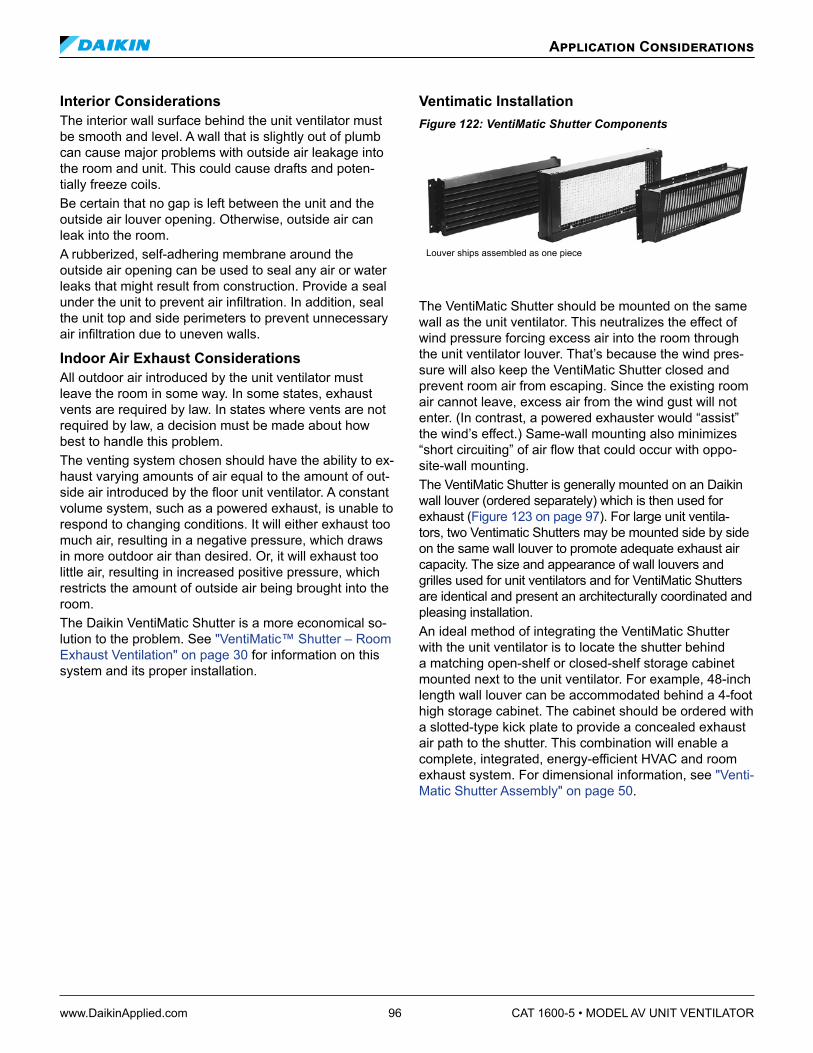
www.DaikinApplied.com 96 CAT 1600-5 • MODEL AV UNIT VENTILATOR
Interior Considerations The interior wall surface behind the unit ventilator must be smooth and level. A wall that is slightly out of plumb can cause major problems with outside air leakage into the room and unit. This could cause drafts and poten-tially freeze coils. Be certain that no gap is left between the unit and the outside air louver opening. Otherwise, outside air can leak into the room. A rubberized, self-adhering membrane around the outside air opening can be used to seal any air or water leaks that might result from construction. Provide a seal under the unit to prevent air infiltration. In addition, seal the unit top and side perimeters to prevent unnecessary air infiltration due to uneven walls.
Indoor Air Exhaust Considerations All outdoor air introduced by the unit ventilator must leave the room in some way. In some states, exhaust vents are required by law. In states where vents are not required by law, a decision must be made about how best to handle this problem. The venting system chosen should have the ability to ex-haust varying amounts of air equal to the amount of out-side air introduced by the floor unit ventilator. A constant volume system, such as a powered exhaust, is unable to respond to changing conditions. It will either exhaust too much air, resulting in a negative pressure, which draws in more outdoor air than desired. Or, it will exhaust too little air, resulting in increased positive pressure, which restricts the amount of outside air being brought into the room. The Daikin VentiMatic Shutter is a more economical so-lution to the problem. See "VentiMatic™ Shutter – Room Exhaust Ventilation" on page 30 for information on this system and its proper installation.
Ventimatic InstallationFigure 122: VentiMatic Shutter Components
Louver ships assembled as one piece
The VentiMatic Shutter should be mounted on the same wall as the unit ventilator. This neutralizes the effect of wind pressure forcing excess air into the room through the unit ventilator louver. That’s because the wind pres-sure will also keep the VentiMatic Shutter closed and prevent room air from escaping. Since the existing room air cannot leave, excess air from the wind gust will not enter. (In contrast, a powered exhauster would “assist” the wind’s effect.) Same-wall mounting also minimizes “short circuiting” of air flow that could occur with oppo-site-wall mounting. The VentiMatic Shutter is generally mounted on an Daikin wall louver (ordered separately) which is then used for exhaust (Figure 123 on page 97). For large unit ventila-tors, two Ventimatic Shutters may be mounted side by side on the same wall louver to promote adequate exhaust air capacity. The size and appearance of wall louvers and grilles used for unit ventilators and for VentiMatic Shutters are identical and present an architecturally coordinated and pleasing installation. An ideal method of integrating the VentiMatic Shutter with the unit ventilator is to locate the shutter behind a matching open-shelf or closed-shelf storage cabinet mounted next to the unit ventilator. For example, 48-inch length wall louver can be accommodated behind a 4-foot high storage cabinet. The cabinet should be ordered with a slotted-type kick plate to provide a concealed exhaust air path to the shutter. This combination will enable a complete, integrated, energy-efficient HVAC and room exhaust system. For dimensional information, see "Venti-Matic Shutter Assembly" on page 50.
Application Considerations

CAT 1600-5 • MODEL AV UNIT VENTILATOR 97 www.DaikinApplied.com
Application Considerations
Figure 123: VentiMatic Shutter Installation
Louver
Outside
Roomside
VentiMatic & Louver Assembly behind cabinet.
Outside
VentiMatic Shutter
Building Wall
The VentiMatic shutter assembly mounts on the same wall as the unit ven-tilator louver, to neutralize wind effect.
Closed Shelf Storage Cabinet with Slotted Kickplate
Exhaust Air
Steel ShutterMounting Plate
Steel Baffle Leaf Support
Flexible Glass Fabric, Silicone-ImpregnatedShutter Leaf
Cabinet -Slotted Kickplate

www.DaikinApplied.com 98 CAT 1600-5 • MODEL AV UNIT VENTILATOR
Window Downdraft ProtectionDowndrafts can be generated in classrooms or other spaces with relatively large windows during prolonged peri-ods of cold outside temperatures. For comfort during such conditions it is necessary to provide some form of down-draft protection. In installations utilizing unit ventilators, the Daikin “DraftStop” system can be used for this purpose.Window downdraft protection is recommended for class-rooms or other spaces where the following conditions exist: • Window area exceeds 40% of the total outside
wall area. • Single-pane glass is used. • Outside temperatures are below 35°F for a
significant portion of the occupied period.The need for window downdraft protection will not al-ways be so clear cut. Where uncertainty exists, a further check can be made by calculating the window heat loss at an outdoor temperature of 35°F. If estimated window heat loss exceeds 250 BTUH/ft., window downdraft pro-tection is recommended. If estimated window heat loss is less than 250 BTUH/ft., the need for downdraft protec-tion is marginal but should not be arbitrarily dismissed. The DraftStop system can be employed even in those marginal applications to provide the occupants comfort without the material, installation and operating cost pen-alty associated with “auxiliary radiation.”
DraftStop SystemThe Daikin DraftStop System is one of the best systems available to address the downdraft problem. This unique system intercepts falling cold air at the window sill level and draws it to the unit ventilator (Figure 124). Cool air from the windows is drawn into a plenum before it is al-lowed to reach the occupants. It then enters the unit’s air stream through the room air damper and becomes part of the normal air circulation pattern. This is accomplished by blocking a portion of the return air grille at the front of the unit ventilator, causing the return air to be drawn in through the ends of the unit.Figure 124: DraftStop Window Downdraft Protection
Cold Air Falling From Window
Downdraft Enclosure (by others)
DraftStop ApplicationThe unit ventilator is ordered with the factory installed Return Air Bottom with DraftStop option to restrict return air flow through the front bottom unit opening and induce air flow through the downdraft return path. The down-draft return path enters through the end compartments of the unit. There are two knockouts on the rear of the unit cabinet (Figure 125) that must be removed to allow proper operation of the DraftStop system.Figure 125: DraftStop Knockouts
End compartment DraftStop knockouts must be removedfor proper DraftStop operation(21-7/8" units only)
Outside Air Intake Opening
14" (356mm)
5" (127mm)
5" (127mm)
The downdraft grilles are installed in cabinetry or other enclosures mounted along the exterior wall on either side of the unit ventilator. This cabinetry is not provided by Daikin. Either a steel bar inlet grille or a stamped inlet grille is fitted to the top rear of the cabinet, flush with the cabinet top. Daikin recommends a 3" wide grille with lengths as specified in Table 50. Note that the maximum lengths are based on maintaining sufficient velocity through the grille in order to capture the downdraft. If the maximum lengths are exceeded, the system will remain operational, but effectiveness will be reduced. A damper may be provided below the grille to allow for balancing of the downdraft airflow.Table 50: Downdraft Grille Lengths
Unit Size Minimum Length Each Side (ft)
Maximum Length Each Side (ft)
07 3' 13'
10 4' 18'
13 5' 22'
15 6' 25'
The unit ventilator may be installed between cabinetry that has a depth equal to the cabinet of the unit, where the downdraft return path is integrated into the rear of the cabinets Figure 125, or used with dedicated down-draft enclosures (provided by others) as illustrated in Figure 124. Special unit end panels are available with cut-outs to provide a return air path when using dedi-cated enclosures. These end panels may or may not be used when the unit is installed between cabinetry. Between the grille and unit a minimum free area of 30 square inches should be maintained along the downdraft return air path.
Application Considerations

CAT 1600-5 • MODEL AV UNIT VENTILATOR 99 www.DaikinApplied.com
Valve SelectionFace and Bypass End-Of-Cycle Valve Sizing & PipingMicroTech II face and bypass damper control units re-quire an end-of-cycle (EOC) valve for each hydronic coil. Unlike modulating valves that require precise control over the variable flow rate through the valve, the EOC valves are either full-open or full-closed, and therefore a proper valve Cv selection is not important. Table 51 gives the pressure drops at various water flow rates for the available EOC valves.
Select an EOC valve based on the application and type of coil to be controlled. For hydronic systems with con-stant flow pumps a 3-way valve is recommended, while 2-way valves are typically used on systems with variable flow pumps. Each hydronic coil in the unit will require its own EOC valve. For hot water or 2-pipe chilled/hot water coils use a normally open valve, and for chilled water coils use a normally closed valve. The 3-way valves can be piped for normally open or normally closed duty (see Figure 126) and it is very important that they are properly installed in the field for the MicroTech control sequence to function correctly. The Normally Open outlet port must be connected to hot water or 2-pipe chilled/hot water coils, and the Normally Closed outlet port must be connected to chilled water coils.
Application Considerations
Table 51: Hot and Chilled Water End-Of-Cycle Valve Selection By Pressure DropValve Pressure Drop at Listed Water Flow Rate
Cv Connection Size
GPM 5 6 7 8 9 10 11 12 13 14 15 16 17 18 19 20
L/s 0.32 0.38 0.44 0.50 0.57 0.63 0.69 0.76 0.82 0.88 0.95 1.01 1.07 1.14 1.20 1.26
3-Way Hot or Chilled Water EOC Valve, FNPT
5.0 3/4 inch
ft H2O 2.3 3.3 4.5 5.9 7.5 9.2 11.2 13.3 15.6 18.1 20.8 23.6 26.7 29.9 33.3 36.9
kPa 6.9 9.9 13.5 17.7 22.3 27.6 33.4 39.7 46.6 54.1 62.1 70.6 79.7 89.4 99.6 110.3
2-Way Hot Water EOC Valve, FNPT, Normally Open / 2-Way Chilled Water EOC Valve, FNPT, Normally Open
7.5 3/4 inch
ft H2O 1.0 1.5 2.0 2.6 3.3 4.1 5.0 5.9 6.9 8.0 9.2 10.5 11.9 13.3 14.8 16.4
kPa 3.1 4.4 6.0 7.8 9.9 12.3 14.8 17.7 20.7 24.0 27.6 31.4 35.4 39.7 44.2 49.0
2-Way Hot Water EOC Valve, FNPT, Normally Open
8.0 1 inch
ft H2O 0.9 1.3 1.8 2.3 2.9 3.6 4.4 5.2 6.1 7.1 8.1 9.2 10.4 11.7 13.0 14.4
kPa 2.7 3.9 5.3 6.9 8.7 10.8 13.0 15.5 18.2 21.1 24.2 27.6 31.1 34.9 38.9 43.1
Figure 126: 3-Way Valve Piping Connections
Inlet Port
Normally OpenOutlet Port
Normally ClosedOutlet Port
3-wayEOC Valve
A
AB
B
Hot Water EOC Valve Piping Hot water (or chilled water/hot water 2-pipe) EOC valves are furnished normally open to the coil. When the valve is de-energized (off) there is full flow through the coil. Energizing the valve shuts off the water flow.
Figure 127: 2-Way Hot Water EOC Valve Piping
Unions
2-wayEOC Valve
S5 Sensor(2-pipe CW/HW Units Only)
Balancing & Shutoff Valve
Unit CoilReturn
Supply
Return
Supply
A B
Shutoff Valve

www.DaikinApplied.com 100 CAT 1600-5 • MODEL AV UNIT VENTILATOR
Figure 128: 3-Way Hot Water EOC Valve Piping
Union
Union
3-wayEOC Valve
Shutoff Valve
(Bypass)
Balancing &Shutoff Valve
Unit CoilReturn
Supply
Return
Supply
S5 Sensor2-pipe CW/HW Units Only)
Balancing Valve
A
AB
B
Chilled Water EOC Valve Piping Chilled water EOC valves are furnished normally closed to the coil. When the valve is de-energized (off) there is no flow through the coil. Energizing the valve allows flow through the coil. Figure 129: 2-Way Chilled Water EOC Valve Piping
Unions
2-wayEOC Valve
Shutoff Valve
Balancing & Shutoff Valve
Unit CoilReturn
Supply
Return
Supply
A B
Figure 130: 3-Way Chilled Water EOC Valve Piping
Union
3-wayEOC Valve
Shutoff Valve
Balancing & Shutoff Valve
Unit CoilReturn
Supply
Return
Supply
A B
Union
AB
Balancing ValveBypass
Application Considerations

CAT 1600-5 • MODEL AV UNIT VENTILATOR 101 www.DaikinApplied.com
Modulating Valve Sizing & PipingThe unit ventilator control valve is expected to vary the quantity of water that flows through the coil in a modulat-ing fashion. Movement of the valve stem should produce a controlled change in the amount of water that flows through the coil. When control valves are oversized (Cv too high) the flow relative to valve position is not linear. For example, assume that, when the control valve is fully open, the pressure drop through the coil is twice as great as the drop through the valve. In this case, the control valve must travel to approximately 50% closed before it can begin to have any influence on the water flow through the coil. The control system, no matter how sophisticated, cannot overcome this. Oversized control valves can also result in hunting which will shorten the life of the valve and actuator and possibly damage the coil. Undersized (Cv to low) control valves will accurately control the flow but will have a very high pressure drop through the valve.
To correctly select the modulating valve: 1. Determine the flow of water and the corresponding
pressure drop through the coil. 2. Obtain the pressure difference between the supply
and return mains. 3. Select a valve (Cv) from Table 52 on the basis of
taking 50% of the available pressure difference (at design flow) between the supply and return mains at the valve location. The valve should have a pressure drop greater than that of the coil. Whenever possible there should be at least 11 feet of water (5psi) (32.9 kPa) pressure drop across the valve.
Modulating valves for water applications can be either 2-way or 3-way. Refer to the modulating valve label to determine the direction of flow. The modulating valve must be installed on the unit for which it was selected. The modulating valve furnished for steam applications is a 2-way, normally open to the coil configuration (see "Steam Valve Sizing & Piping" on page 103 for application).
Application Considerations
Table 52: Hot and Chilled Water Modulating Valve Selection By Flow RateValve Pressure Drop at Listed Water Flow Rate
Cv Connection Size
GPM 1 2 3 4 5 6 7 8 9 10 11 12 13 14 15 16 17 18 19 20
L/s 0.06 0.13 0.19 0.25 0.32 0.38 0.44 0.50 0.57 0.63 0.69 0.76 0.82 0.88 0.95 1.01 1.07 1.14 1.20 1.26
Hot Water 2-Way Modulating Valve, Normally Open / Chilled Water 2-Way Modulating Valve, Normally ClosedHot or Chilled Water 3-Way Modulating Valve
0.73 1/2 inchft H2O 4.3 17.3 39.0 – – – – – – – – – – – – – – – – –
kPa 12.9 51.8 116.4 – – – – – – – – – – – – – – – – –
1.8 1/2 inchft H2O – – 6.4 11.4 17.8 25.6 34.9 45.6 – – – – – – – – – – – –
kPa – – 19.2 34.0 53.2 76.6 104.3 136.2 – – – – – – – – – – – –
4.6 1/2 inchft H2O – – – – – – – 7.0 8.8 10.9 13.2 15.7 18.4 21.4 24.5 27.9 31.5 35.3 39.4 –
kPa – – – – – – – 20.9 26.4 32.6 39.4 46.9 55.1 63.9 73.3 83.4 94.2 105.6 117.6 –
7.3 3/4 inchft H2O – – – – – – – – – – – – 7.3 8.5 9.7 11.1 12.5 14.0 15.6 17.3
kPa – – – – – – – – – – – – 21.9 25.4 29.1 33.1 37.4 41.9 46.7 51.8
11.6 1 inchft H2O – – – – – – – – – – – – – – – – – 5.6 6.2 6.9
kPa – – – – – – – – – – – – – – – – – 16.6 18.5 20.5

www.DaikinApplied.com 102 CAT 1600-5 • MODEL AV UNIT VENTILATOR
Hot Water Modulationg Valve PipingModulating hot water (or chilled water/hot water 2-pipe) valves are furnished normally open to the coil. When the valve is de-energized (off) there is full flow through the coil. Energizing the valve allows a varying amount of water to bypass the coil. Figure 131: 2-Way Hot Water Modulating Valve Piping
Unions
2-wayModulating Valve
S5 Sensor(2-pipe CW/HW Units Only)
Balancing & Shutoff Va;ve
Unit CoilReturn
Supply
Return
Supply
Shutoff Valve
Figure 132: 3-Way Hot Water Modulating Vlave Piping
Union
3-wayModulating Valve
S5 Sensor (2-pipe CW/HW Units Only)
Balancing & Shutoff Valve
Unit CoilReturn
Supply
Return
Supply
Shutoff Valve
Union
Balancing Valve
N.C.
N.O.
Common
Chilled Water Modulating Valve Piping Modulating chilled water valves are furnished normally closed to the coil. When the valve is de-energized (off) there is no flow through the coil. Energizing the valve allows flow through the coil Figure 133: 2-Way Chilled Water Modulating Valve Piping
Unions
2-wayModulating Valve
Balancing & Shutoff Valve
Unit CoilReturn
Supply
Return
Supply
Shutoff Valve
Figure 134: 3-Way Chilled Water Modulating Valve Piping
Union
3-wayModulating Valve
Balancing & Shutoff Valve
Unit CoilReturn
Supply
Return
Supply
Shutoff Valve
Union
Balancing Valve
N.C.
N.O.
Common
Application Considerations

CAT 1600-5 • MODEL AV UNIT VENTILATOR 103 www.DaikinApplied.com
Steam Valve Sizing & Piping End-Of-Cycle Steam Valve Selection End-of-cycle, steam valves are either full-open or full-closed. To select an end-of-cycle steam valve: 1. Obtain the supply steam inlet pressure. 2. Determine the actual heat requirement of the space
to be heated. 3. Select a steam valve (Cv) based on taking 10% of the
inlet steam pressure. For example, for a system with an inlet pressure of 2 psig, the valve should be sized based on a 0.2 psig pressure drop. The valve must have a capacity greater than or equal to that of the space to be heated.
Table 53 gives the steam capacity based on a pressure drop equal to 10% of the inlet pressure.Table 53: EOC Steam Valve Selection
Cv Connection Size
psig 1 2 3 4 5 6
kPa 6.9 13.8 20.7 27.6 34.5 41.4
EOC Steam Valve Selection
8.00 1 inchMBh 34.3 50.0 63.0 74.7 85.6 96.0
Watts 10065 14660 18461 21886 25090 28148
1 Based on 1150 Btu/lb of steam
Modulating Steam Valve Selection The steam modulating control valve is expected to vary the quantity of steam through the coil. Any movement of the valve stem should produce some change in the steam flow rate. To select a modulating steam valve: 1. Obtain the supply steam inlet pressure. 2. Determine the actual heat requirement of the space
to be heated. 3. Select a valve (Cv) from Table 54, which gives the
capacity range based on a 60% pressure drop at the low end of the range and 100% pressure drop at the high end of the range.
For example: With 2 psig (13.8 kPa) inlet pressure, the valve with port code 4, in the full open position, would have a 1.2 psig (8.3 kPa) pressure drop (60% of 2 psig) at 65 MBh (19,189 watts) and a 2 psig pressure drop at 82 MBh (24,125 watts). The valve should have a capac-ity less than or equal to the space to be heated.
Application Considerations
Table 54: Modulating 2-Way Steam Valve Capacity1, Normally OpenValve Capacity1
Min Max Min Max Min Max Min Max Min Max Min Max
Cv Connection Size
psig 1 2 3 4 5 6
kPa 6.9 13.8 20.7 27.6 34.5 41.4
Modulating 2-Way Steam Valve Capacity, Normally Open
0.73 1/2 inchMBh 6.5 8.3 9.5 12.0 11.9 15.1 14.2 17.9 16.2 20.5 18.2 23.0
Watts 1905 2432 2784 3517 3488 4425 4162 5246 4748 6008 5334 6741
2.2 1/2 inchMBh 16.1 20.4 23.4 29.7 29.5 37.3 34.9 44.2 40.0 50.6 44.9 56.8
Watts 4718 5979 6858 8704 8646 10932 10228 12954 11723 14829 13159 16646
4.6 1/2 inchMBh 41.1 52.0 59.9 75.8 75.3 95.2 89.3 113.0 102.2 129.3 114.7 145.1
Watts 12045 15240 17555 22215 22068 27900 26171 33117 29952 37894 33615 42525
7.3 3/4 inchMBh 65.3 82.6 95.1 120.3 119.5 151.2 141.7 179.3 162.2 205.2 182.1 230.3
Watts 19138 24208 27871 35256 35022 44312 41528 52548 47536 60138 53368 67494
11.6 1 inchMBh 103.8 131.2 151.1 191.1 189.9 240.2 225.2 284.8 257.8 326.1 289.3 365.9
Watts 30421 38451 44283 56006 55654 70396 66000 83467 75554 95570 84785 107235
18.5 1 inchMBh 165.5 209.3 240.9 304.7 302.8 383.1 359.1 454.3 411.1 520.0 461.4 583.6
Watts 48503 61340 70601 89299 88742 112276 105242 133142 120482 152397 135223 171036
1 Based on 1150 Btu/lb of steam.

www.DaikinApplied.com 104 CAT 1600-5 • MODEL AV UNIT VENTILATOR
Steam Valve Piping End-of-cycle (EOC) and modulating valves for steam ap-plications are 2-way, normally open, angle pattern valves. When the coil is de-energized (off) the steam flows through the coil. Energizing the EOC valve shuts off the flow of steam to the coil. Energizing the modulating valve varies the flow of steam in a modulating fashion. Refer to the steam valve label to determine the direction of flow. The steam valve must be installed on the unit for which it was selected. All valves are shipped loose to help prevent shipping dam-age and to provide the installing contractor with maximum flexibility in making the field piping connection. The valves are field piped by others. They are factory wired for field hook-up. Notes: 1. Refer to the label furnished on 2-way valves to
determinedirectionofflowthroughthevalve. 2. The control valve must be installed on the unit in
which it was shipped. Indiscriminate mixing of valves among units can result in valves not properly sized forthedesiredflowrate.
3. The control valve should be installed so that there is 2" (51mm) minimum clearance to remove the actuator from the valve body. Provide unions for the removal of the unit coil and/or control valve. This is a future service consideration.
Figure 135: 2-Way Steam Valve Piping
Return
Shutoff Valve
Shutoff Valve
Supply
Return
Supply
Unit Coil
Equalizing Line
Steam Trap
Union
Application Considerations

CAT 1600-5 • MODEL AV UNIT VENTILATOR 105 www.DaikinApplied.com
Daikin Applied Unit Ventilator – Model AV Guide Specifications General Furnish and install where shown on plans, a complete unit ventilator with capacities, airflow, and configuration as listed on unit schedule.
Unit Construction All internal sheet metal parts must be made of galva-nized steel to inhibit corrosion. The entire frame must be welded construction to provide strength and rigidity. Hidden reinforced top panel support shall be integral with the frame and support the fan assembly. Frames assembled with sheet metal fasteners shall not be ac-ceptable. Unit shall be of a draw-thru design. Blow-thru design is not acceptable. Unit shall have a built-in metal wire raceway from one end compartment to the other.
Cabinets Exterior cabinet panels shall be constructed of heavy-gauge steel. All sheet metal panels must be cleaned and phosphatized, then painted electrostatically with an oven baked environmentally friendly thermosetting urethane powder finish.
Floor Units Floor mounted units shall have an integral pipe tunnel for convenient crossover of piping or electrical wiring in accordance with local and National Electric Codes (N.E.C.). The front surface shall consist of three sepa-rate, removable panels easily handled by one person. Control compartment must be accessible without remov-ing the entire front panel. Unit top shall have two access doors (one at each end) for access to motor and bear-ings. Unit discharge grille shall be welded continuous bar type with round edged steel bars placed for a 10° vertical deflection. [A 1/4" painted galvanized mesh shall be furnished and located beneath discharge grille.] Unit top surface shall be supplied with a textured non-glare paint surface that resists scuffing and hides fingerprints. Units shall come with front adjustable leg levelers. End panels shall ship separately, individually wrapped in plastic and boxed to prevent damage during construction.
Room Air Fans And Motor The unit fan and motor assembly shall be of a modu-lar construction so that it is removable from the top for service, maintenance and access to the coil section for cleaning. The motor and fan assembly shall be low speed design to assure maximum quietness and efficiency. Fans shall be double inlet, forward curved centrifugal type with offset aerodynamic blades. Assembly shall be statically and dynamically balanced. Fan housings shall be steel construction, incorporating logarithmic expansion for qui-eter operation. Fan shaft shall be 1-1/4" diameter hollow steel with 1-1/4" end bearing. Fan and motor assembly
shall be direct drive type. Motor speed shall be controlled by factory mounted multi-tap transformer for High-Medi-um-Low-Off speeds. Fan/coil arrangement shall be draw-thru design for uniform coil face velocity and discharge air temperature. Motors shall be 115/60/1 NEMA permanent split capacitor (PSC), or [Optional] Electrically Commutat-ed (ECM) plug-in type designed specifically for unit ven-tilator operation. PSC motor speed shall be controlled by factory mounted multi-tap transformer for High-Medium-Low-Off speeds. [Optional] EC motor shall be controlled by discrete speed taps for High-Medium-Low-Off speeds. [Optional] EC motor with variable airflow control shall vary fan speed to deliver 50%-100% nominal unit airflow based on 0-10vdc input signal. Motors shall be located out of the airstream and have an internal thermal overload device (auto reset). Fan motors and controls shall have each hot line protected by factory installed cartridge type fuse(s). Motors shall have sleeve type bearings and require oiling no more than once annually. Units shall have shaft bear-ing located out of the air stream. Bearings in the airstream are not acceptable.
Face And Bypass Damper Each unit shall be provided with a factory-installed face and bypass damper, constructed of aluminum. The long sealing surfaces of the damper shall seal positively against stops fitted with extruded EPDM rubber seals. Face and bypass damper stops not fitted with seals shall not be acceptable. The damper ends shall have blended mohair seals glued along the ends for a positive seal. Plastic clip-on brush end seals will not be acceptable. The unit design shall incorporate the face and bypass damper to prevent coil surface wiping and be before the fan in a draw through configuration. Face and bypass damper positioned in the direct discharge of the room fan is not acceptable. The face and bypass damper shall be arranged so a dead air space results between the coil and the damper in a full bypass condition to minimize heat pick up.
Outdoor And Room Air Dampers Each unit shall be provided with separate room air and outdoor air dampers. The room air damper shall be constructed of aluminum using metal-forming techniques to resist twisting and shall be counterbalanced against back pressure. Outdoor air damper shall be two-piece double-wall construction with 1/2" thick, 1.5 lbs. density fiberglass insulation encapsulated between welded 20 ga. galvanized steel blades for rigidity and to inhibit corrosion, and have additional insulation on the exterior surfaces of the damper blade and on the ends of the outdoor air chamber. Dampers shall be fitted with mohair seals along all the sealing edges. Dampers shall use turned-metal principle on long closing ends with no metal-to-metal contact. No plastic or rubber gaskets shall be acceptable. Damper bearings shall be made of nylon or other material which does not require lubrication.
Guide Specifications

www.DaikinApplied.com 106 CAT 1600-5 • MODEL AV UNIT VENTILATOR
Drain Pan All units shall have a drain pan constructed of corrosion-resistant galvanized steel and shall be insulated. A drain outlet shall be provided on both ends of the pan. The drain hand of connection shall be easily field-reversed to the opposite end. The drain pan shall be able to be sloped in either direction for proper condensate removal. Drain shall be provided with an optional secondary, over-flow drain connection on both ends of the pan. [Option: Drain pan shall be constructed of stainless steel.]
Agency Listing Unit ventilators shall be listed by Underwriters Labo-ratories Inc. (U.L.) for the United States and Canada. Unit ventilation rate to be certified and tested per Air Conditioning, Heating and Refrigeration Institute (AHRI) standard 840. All units with chilled water coils shall be AHRI certified for performance. Motors shall conform to the latest applicable requirements of NEMA, IEEE, ANSI, and NEC standards.
Coils All hydronic coils shall be constructed with copper tubes and mechanically bonded aluminum corrugated plate fins. All coils shall have aluminum individual unshared fin surfaces. An air brake shall exist between coils. Water coils shall be furnished with a threaded drain plug at the lowest point. A manual air vent shall be provided at the high point of the coil. Steam coils shall be double tube, steam distributing freeze-resistant type. Steam coils shall be furnished with a factory installed pressure equal-izing device (vacuum breaker) to prevent the retention of condensate in the coil. Tubing shall be provided for field connection to the return line beyond the trap. Direct expansion coils (DX) – all DX coils must be supplied with factory-installed thermal expansion valve and a DX low temperature limit. This expansion valve must be sized for the manufacturer’s matching remote condensing unit. Electric heat coils shall be open wire. Cal rods inserted into a tube shall not be acceptable.
Filters Filter shall be one-piece design located to provide filtra-tion of the outdoor air/return air mixture to assure even dust loading and balanced airflow in lieu of separate filters for outdoor air and return. [Throwaway filter (all ex-cept electric heat)] [wire, mesh, permanent filter (electric heat units)] shall be factory furnished initially installed in all units. [Option: Furnish _______ extra set(s) of throwaway filters.] [Option: Furnish one set of wire mesh permanent filters as final filter.] [Option: Furnish one set of renewable (structural painted metal frame with glass fiber media) filters as final filter.]
Condensing Units Condensing unit sizes shall be specifically matched to the unit ventilator size. The remote condensing unit shall be U.L. listed with brass service valves, internal high pressure control, low ambient air temperature thermo-stat. Sweat type tubing connections shall be furnished. The installing contractor shall provide interconnecting copper tubing of the size recommended by the condens-er manufacturer. The installing contractor shall charge the system with refrigerant in accordance with the manu-facturer’s instructions.
Temperature Controls Each unit ventilator shall be furnished with a factory in-stalled and wired, microprocessor based DDC Unit Ven-tilator Controller (UVC), by the manufacturer of the unit ventilator, which is pre-programmed, factory pre¬tested prior to shipment and capable of complete, stand¬alone unit control, master-slave arrangement or incorporation into a building-wide network using an optional plug-in communication module. The UVC shall be prepro-grammed with the application code required to operate the unit using ASHRAE Cycle II. The unit control system shall include all required temperature sensors, input/out-put boards, main microprocessor modules, Local User Interface (referred to as LUI) Touch Pad with Digital LED Display, wiring, 24 volt power and direct coupled damper actuators. The UVC shall support up to 6 analog inputs, 12 binary inputs, and 9 binary outputs plus additional I/O points of 4 analog inputs and 8 binary outputs.
Network System 1. The unit control system shall perform all unit control
functions, unit diagnostics and safeties. The unit shall operate in the standalone or network capable mode of operation. Field furnished and installed controls shall not be allowed. When network capable, network communication modules shall be factory installed, tested and able to communicate via plug-in communication modules that connect directly to the UVC using:
SELECT one: a. LonMark Space Comfort Control that supports the
LonMark SCC profile number 8500-10 allowing LonWorks network communication capability to the UVC.
b. BACnet Master Slave/Token Passing (MS/TP) allowing the UVC to inter-operate with systems that use the BACnet (MS/TP) protocol with a conformance level of 3 meeting the requirements of ANSI/ASHRAE 135-1955 standard for BACnet systems.
2. Controls shall allow monitoring and adjustment from a portable IBM compatible PC using the applicable software. When using this PC and software, the unit shall be capable of reacting to commands for changes in control sequence and set points.
Guide Specifications

CAT 1600-5 • MODEL AV UNIT VENTILATOR 107 www.DaikinApplied.com
Room Temperature Sensor And Tenant Override Options Unit Mounted All units shall come equipped with a factory mounted room temperature sensor located in a sampling cham-ber (front, center panel) where room air is continuously drawn through for fast response to temperature changes in the room. When using a remote wall-mounted temper-ature sensor the ability shall exist to simply disconnect the unit-mounted temperature sensor using the provided quick disconnect plug. Tenant override switch shall be factory mounted next to the Local User Interface (LUI) Touch Pad to provide a momentary contact closure that causes the unit to enter the “tenant override” operating mode for a set time period (adjustable) of 120 minutes. The room temperature sensor and override switch shall (SELECT one): a. both be unit mounted. b. be an optional wall mounted temperature sensor, with
integral tenant override capability
Wall Mounted Sensor with Tenant Override A thermistor type temperature sensor with integral tenant override and status LED shall be furnished with the unit ventilators. SELECT one: a. Remote wall mounted sensor with tenant override b. Expanded remote wall mounted sensor with room set
point adjustment capability of zero plus or minus 3°F (1.5°C)
c. Deluxe remote wall mounted sensor with room set point adjustment capability ranging from 54°F (12°C) to 82°F (28°C)
Night Controls Night set-back/set-up control shall be provided by (SELECT one): a. A factory mounted and wired digital time clock
(optional for standalone operation) which shall cycle the unit ventilator through occupied and unoccupied modes in accordance with one of twenty (20) user programmed time schedules.
b. A remote mounted time clock as described in the temperature control specification and provided by the automatic temperature controls contractor. The unit in standalone mode shall have a single set of dry-contacts to signal unoccupied or occupied mode.
c. The network DDC control system.
External Signal Connections The unit shall have three (3) multi-pin External Signal Connection Plugs factory provided and pre-wired with short wire whips that are capped for field wiring of: a. Remote Wall Mounted Temperature Sensor.
b External Input Signals (by others) availability dependent upon unit configuration: unoccupied, remote shutdown, ventilation lockout, dew point/ humidity, or exhaust interlock signals.
c. External Output Options (by others) availability dependent upon unit configuration: lights on/off, motorized water valve open/close, fault indication signal, pump restart, exhaust fan on/off or auxiliary heat signal.
[Accessory] Outdoor Air Intake Louver Intake louvers shall be in the quantity and size shown on the plans and specifications, and as manufactured by Daikin Applied.
[Accessory] Horizontal Blade Aluminum LouverAluminum masonry louver shall be constructed with horizontal chevron-type, heavy-gauge aluminum blades and aluminum frame. The standard aluminum alloy shall be suitable for color anodizing (by others) or for factory painting. Weep holes shall be provided in the louver frame. A diamond pattern mesh screen shall be furnished on the interior side of the louver. Expanded metal is not acceptable. Louver shall be fabricated of mill finish 6063-T6 aluminum. [Optional: Louver shall be (1) aluminum with clear anodized finish (2) aluminum with an oven-baked powder paint finish. (3) unpainted.]
[Accessory] Vertical Blade LouverVertical blade aluminum louver shall be constructed with double-break, aluminum blades for mounting in panel wall or masonry wall applications. The louver frame shall be heavy-gauge aluminum, 2-1/4" deep in direction of airflow, and have weep holes along face of bottom edge. The standard aluminum alloy shall be suitable for color anodizing (by others) or for factory painting. A diamond pattern mesh screen shall be provided on the interior side of the louver. Louver shall be fabricated of mill fin-ish 6063-T6 aluminum. [Optional: Louver shall be (1) aluminum with clear anodized finish (2) aluminum with an oven-baked powder paint finish (3) unpainted. A four-sided flange shall be provided around perimeter of intake of same material and finish as louver.]
[Accessory] GrilleDecorative aluminum intake grille shall be constructed of heavy-gauge 6063-T6 extruded aluminum with square holes to match the louver opening, maximizing the air opening. The grille shall come with holes for mounting to building exteriors. The standard extruded 6063-T6 alu-minum shall be suitable for color anodizing (by others) or for factory painting.
Guide Specifications

Daikin Applied Training and Development
Now that you have made an investment in modern, efficient Daikin equipment, its care should be a high priority. For training information on all Daikin HVAC products, please visit us at www.DaikinApplied.com and click on Training, or call 540-248-9646 and ask for the Training Department.
Warranty
All Daikin equipment is sold pursuant to its standard terms and conditions of sale, including Limited Product Warranty. Consult your local Daikin Applied representative for warranty details. Refer to Form 933-430285Y. To find your local Daikin Applied representative, go to www.DaikinApplied.com.
Aftermarket Services
To find your local parts office, visit www.DaikinApplied.com or call 800-37PARTS (800-377-2787). To find your local service office, visit www.DaikinApplied.com or call 800-432-1342.
This document contains the most current product information as of this printing. For the most up-to-date product information, please go to www.DaikinApplied.com.
Products manufactured in an ISO Certified Facility.
CAT 1600-5 ©2017 Daikin Applied (03/17) | (800) 432–1342 | www.DaikinApplied.com