
CAT interface - Ham Radio · PDF fileINTRODUCTION In order to use Ham Radio Deluxe to control...
32
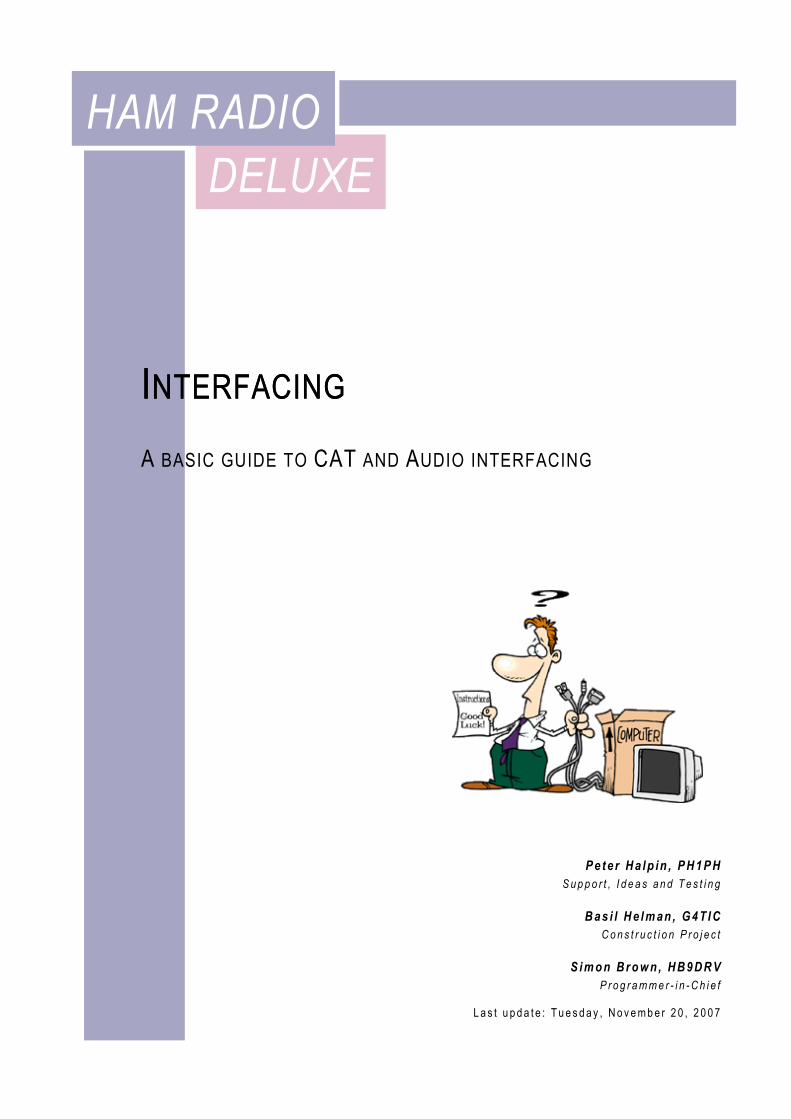
DELUXE HAM RADIO I NTERFACING Peter Halpin, PH1PH Support, Ideas and Testing Basil Helman, G4TIC Construction Project Simon Brown, HB9DRV Programmer-in-Chief Last update: Tuesday, November 20, 2007 A BASIC GUIDE TO CAT AND A UDIO INTERFACING I NTERFACING
Transcript of CAT interface - Ham Radio · PDF fileINTRODUCTION In order to use Ham Radio Deluxe to control...
DELUXE HAM RADIO
INTERFACING
P e t e r H a l p in , P H 1 P H S u p p o r t , I d e a s a n d T e s t i n g
B a s i l H e l m an , G 4T I C
C o n s t r u c t i o n P r o j e c t
S i m o n B r o w n , H B 9D R V P r o g r a m m e r - i n - C h i e f
L a s t u p d a t e : T u e s d a y , N o v e m b e r 2 0 , 2 0 0 7
A BASIC GUIDE TO CAT AND AUDIO INTERFACING
INTERFACING

U s e r G u i d e
2
The IC-703s used in this project were supplied by Martin Lynch and Sons of London.
Special thanks are due to Chris Taylor for his friendly and efficient service.
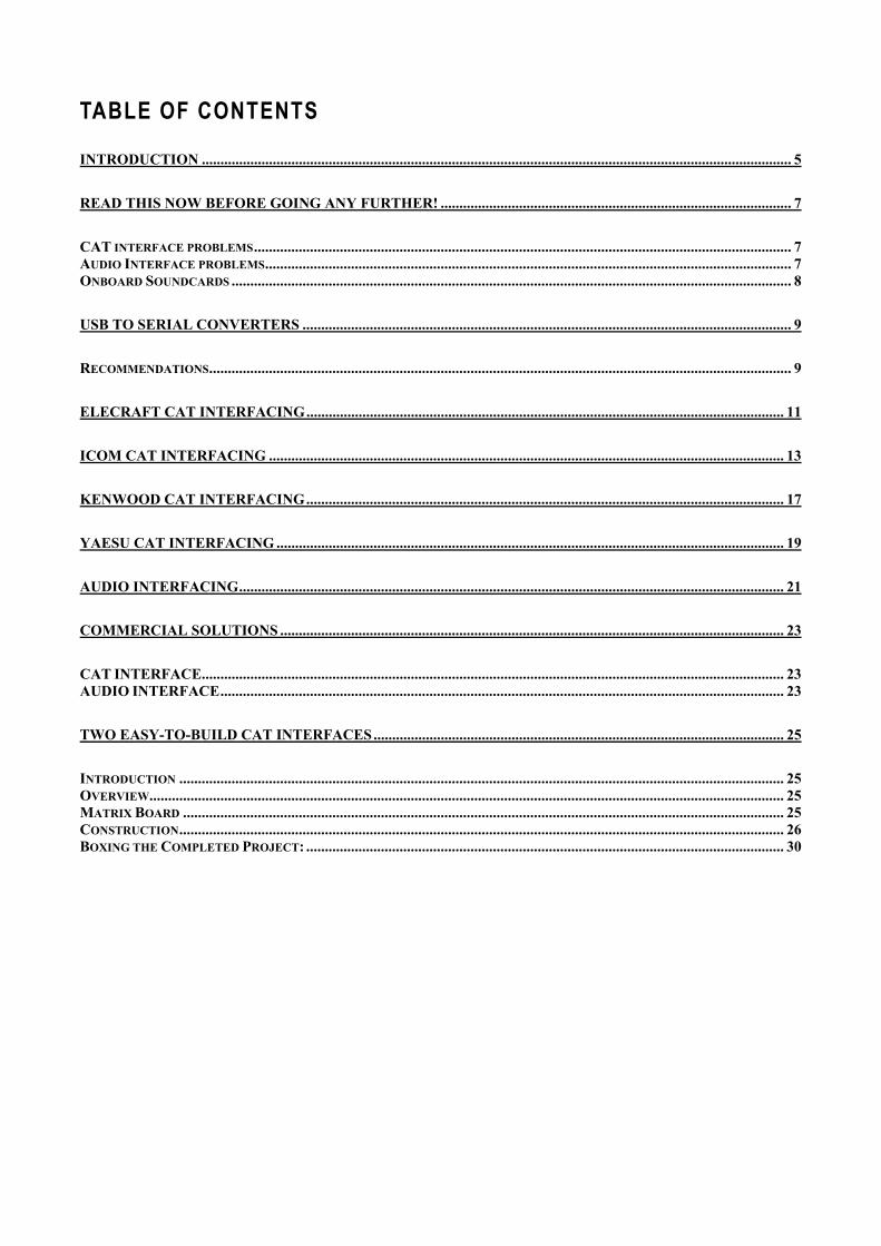
TABLE OF CONTENTS
INTRODUCTION .............................................................................................................................................................. 5
READ THIS NOW BEFORE GOING ANY FURTHER! .............................................................................................. 7
CAT INTERFACE PROBLEMS ................................................................................................................................................ 7 AUDIO INTERFACE PROBLEMS ............................................................................................................................................. 7 ONBOARD SOUNDCARDS ...................................................................................................................................................... 8
USB TO SERIAL CONVERTERS ................................................................................................................................... 9
RECOMMENDATIONS ............................................................................................................................................................ 9
ELECRAFT CAT INTERFACING ................................................................................................................................ 11
ICOM CAT INTERFACING .......................................................................................................................................... 13
KENWOOD CAT INTERFACING ................................................................................................................................ 17
YAESU CAT INTERFACING ........................................................................................................................................ 19
AUDIO INTERFACING .................................................................................................................................................. 21
COMMERCIAL SOLUTIONS ....................................................................................................................................... 23
CAT INTERFACE ............................................................................................................................................................ 23 AUDIO INTERFACE ....................................................................................................................................................... 23
TWO EASY-TO-BUILD CAT INTERFACES .............................................................................................................. 25
INTRODUCTION .................................................................................................................................................................. 25 OVERVIEW.......................................................................................................................................................................... 25 MATRIX BOARD ................................................................................................................................................................. 25 CONSTRUCTION .................................................................................................................................................................. 26 BOXING THE COMPLETED PROJECT: ................................................................................................................................ 30

INTRODUCTION In order to use Ham Radio Deluxe to control your rig you will require a CAT interface. Some radios supported by Ham Radio Deluxe already have built-in RS232 interfaces (the FT-847 is an example). Please check your radio’s handbook for more information. Examples of CAT interfaces are Icom’s CT-17 and Yaesu’s FIF-232 and CT-62.
To use PSK31 Deluxe or other digital mode software you will need an audio interface. You can either make your own or purchase a solution. Examples of audio interfaces are the Tigertronics SignaLink and West Mountain Radio’s NoMic.
As far as I aware, the only commercial interfaces offering both CAT and audio interfacing are West Mountain Radio’s RigBlaster Pro and G3VFP’s CatOpto models.
I am deeply grateful to the designers of the various interfaces mentioned here: without their practical expertise this document would not have been possible. Please note that the Ham Radio Deluxe Development Team have not personally tested all circuits shown here: we can accept no liability whatsoever for damage resulting from the use of any of these designs.

READ THIS NOW BEFORE GOING ANY FURTHER! There are many problems that a newcomer can come across while trying to set up both CAT and Audio interfaces: I’ll try to help you avoid the most common problems.
CAT INTERFACE PROBLEMS 1. Ham Radio Deluxe displays the error Access Denied.
Some previously accessed software will cause problems for the operating system by holding a comport open, thus denying your CAT interface access. Only one program can open a comport at a same time. PDA / GSM software is one example. The simplest way to deal with this is a reboot: the offending program will no longer have control over the port.
2. Some notebook serial ports can’t supply enough current and/or voltage to operate homemade interface cables that rely on the serial port for power. You will have to either make up an interface to a different design, or use external power.
3. Ground loops can be a problem. Fully isolated interfaces are probably the only real option here. Taking all precautions to avoid ground loops should be a matter of course.
AUDIO INTERFACE PROBLEMS 1. Probably the most common causes of problems are
overdriving the rig, and ground loops. Avoiding ground loops is generally not too difficult if you use isolated input and outputs. See the circuit of the homebrew interface in the AUDIO INTERFACING chapter to see how it can be done. Under no circumstances should you use un-isolated connections: they lead to ground loops, and will in all probability introduce hum and other unwanted artifacts on your signal. One disadvantage of using a waterfall display is that you can see the other guy’s filthy signal – but not your own. I know that some people get away with it – but the risk just isn’t worth it.
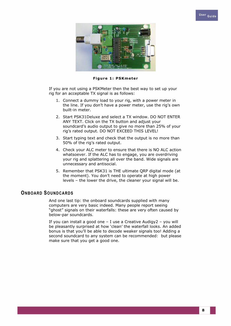
2. Overdriving the rig will lead to splatter and deformed signals. Good operators do not splatter! There’s a very useful little gadget called the PSKMeter that can be obtained from http://www.ssiserver.com/info/pskmeter/ . This makes it impossible to overdrive your rig, yet obtain maximum clean output at all times. I use one myself – it’s ideal. The only drawback is that it requires a serial port: this can be a problem with notebooks and the like – but see the next chapter for more info.
U s e r G u i d e
8
Figure 1: PSKmeter
If you are not using a PSKMeter then the best way to set up your rig for an acceptable TX signal is as follows:
1. Connect a dummy load to your rig, with a power meter in the line. If you don’t have a power meter, use the rig’s own built-in meter.
2. Start PSK31Deluxe and select a TX window. DO NOT ENTER ANY TEXT. Click on the TX button and adjust your soundcard’s audio output to give no more than 25% of your rig’s rated output. DO NOT EXCEED THIS LEVEL!
3. Start typing text and check that the output is no more than 50% of the rig’s rated output.
4. Check your ALC meter to ensure that there is NO ALC action whatsoever. If the ALC has to engage, you are overdriving your rig and splattering all over the band. Wide signals are unnecessary and antisocial.
5. Remember that PSK31 is THE ultimate QRP digital mode (at the moment). You don’t need to operate at high power levels – the lower the drive, the cleaner your signal will be.
ONBOARD SOUNDCARDS And one last tip: the onboard soundcards supplied with many computers are very basic indeed. Many people report seeing “ghost” signals on their waterfalls: these are very often caused by below-par soundcards.
If you can install a good one – I use a Creative Audigy2 – you will be pleasantly surprised at how ‘clean’ the waterfall looks. An added bonus is that you’ll be able to decode weaker signals too! Adding a second soundcard to any system can be recommended: but please make sure that you get a good one.
USB TO SERIAL CONVERTERS Many – if not all - modern notebook computers do not come supplied with RS232 serial ports but with USB ports. In order to use a CAT interface with one of these you will require a USB<>Serial port adapter/converter.
Some users have reported problems when using these converters: in one case it was necessary to purchase a different model, while with others a simple driver update was all that was required. The general consensus is that the default driver supplied with Windows XP is generally sufficient to solve any problems.
HRD tests COM1 through to COM255 and only lists the COM ports that (according to Windows) are configured on the computer and can be accessed.
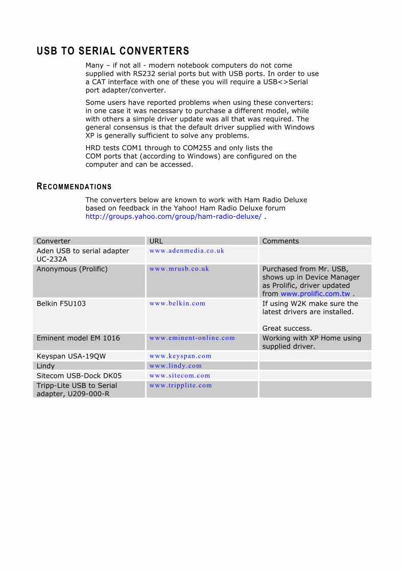
RECOMMENDATIONS The converters below are known to work with Ham Radio Deluxe based on feedback in the Yahoo! Ham Radio Deluxe forum http://groups.yahoo.com/group/ham-radio-deluxe/ .
Converter URL Comments Aden USB to serial adapter UC-232A
www.adenmedia.co .uk
Anonymous (Prolific) www.mrusb.co.uk Purchased from Mr. USB, shows up in Device Manager as Prolific, driver updated from www.prolific.com.tw .
Belkin F5U103 www.belkin.com If using W2K make sure the latest drivers are installed. Great success.
Eminent model EM 1016 www.eminent-onl ine.com Working with XP Home using supplied driver.
Keyspan USA-19QW www.keyspan.com Lindy www.lindy.com Sitecom USB-Dock DK05 www.si tecom.com Tripp-Lite USB to Serial adapter, U209-000-R
www.tr ippl i te .com

ELECRAFT CAT INTERFACING
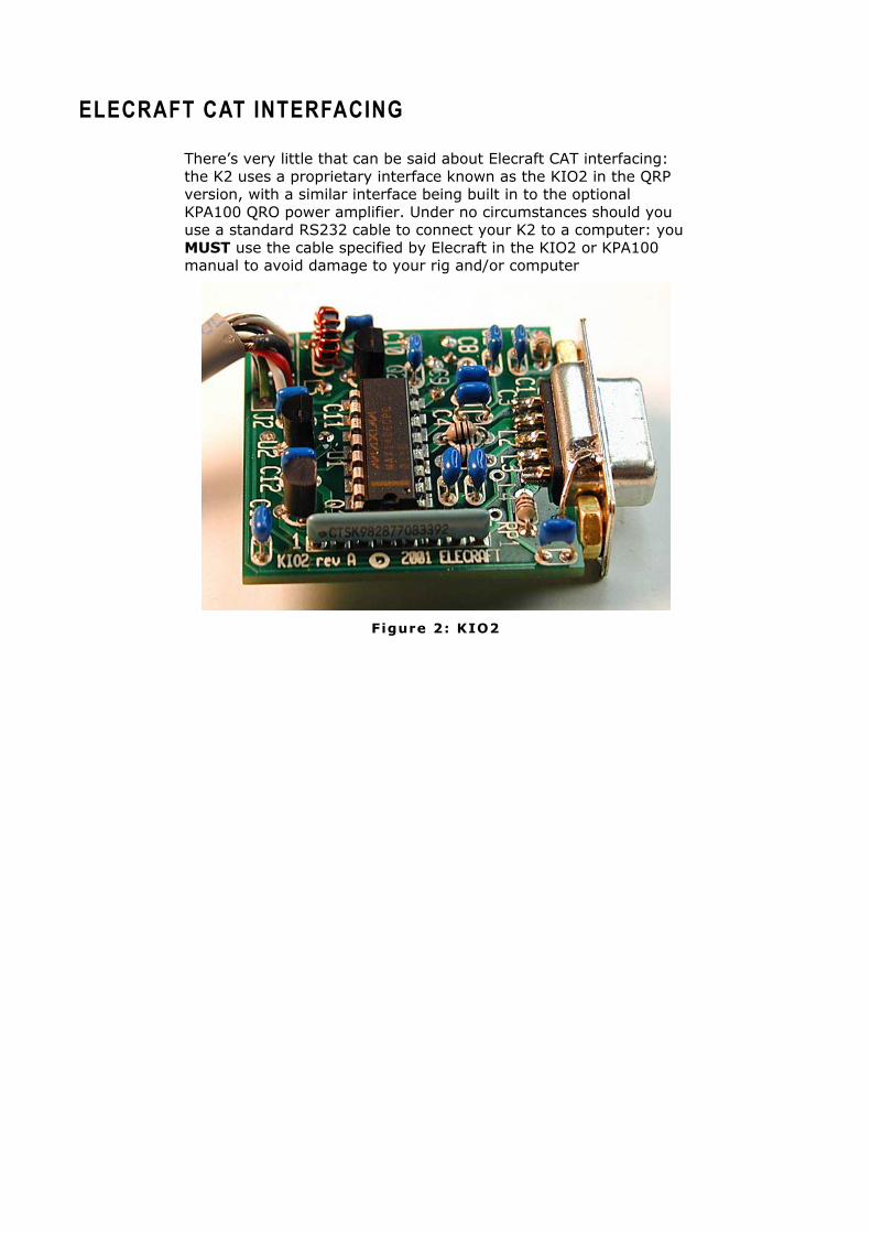
There’s very little that can be said about Elecraft CAT interfacing: the K2 uses a proprietary interface known as the KIO2 in the QRP version, with a similar interface being built in to the optional KPA100 QRO power amplifier. Under no circumstances should you use a standard RS232 cable to connect your K2 to a computer: you MUST use the cable specified by Elecraft in the KIO2 or KPA100 manual to avoid damage to your rig and/or computer
Figure 2: KIO2

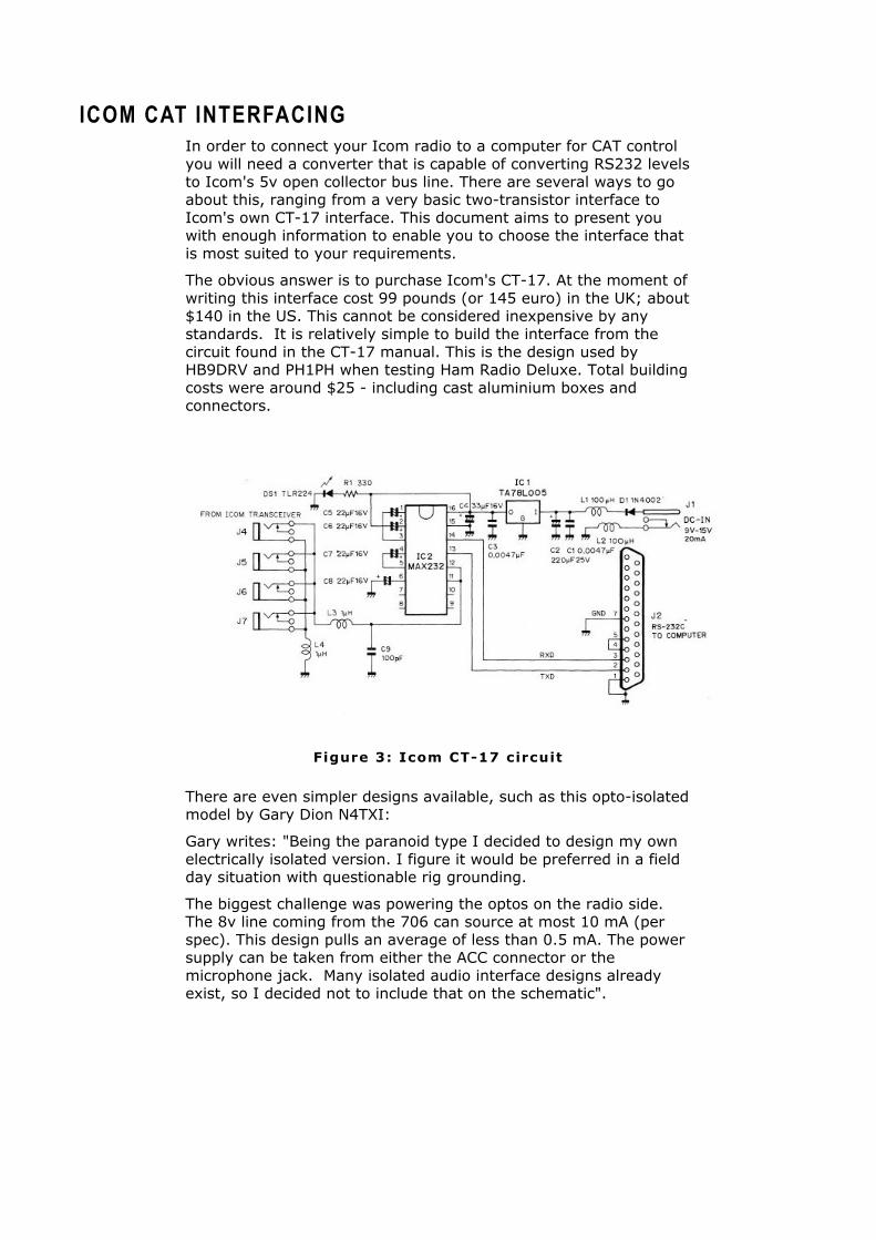
ICOM CAT INTERFACING In order to connect your Icom radio to a computer for CAT control you will need a converter that is capable of converting RS232 levels to Icom's 5v open collector bus line. There are several ways to go about this, ranging from a very basic two-transistor interface to Icom's own CT-17 interface. This document aims to present you with enough information to enable you to choose the interface that is most suited to your requirements.
The obvious answer is to purchase Icom's CT-17. At the moment of writing this interface cost 99 pounds (or 145 euro) in the UK; about $140 in the US. This cannot be considered inexpensive by any standards. It is relatively simple to build the interface from the circuit found in the CT-17 manual. This is the design used by HB9DRV and PH1PH when testing Ham Radio Deluxe. Total building costs were around $25 - including cast aluminium boxes and connectors.
Figure 3: Icom CT-17 circuit
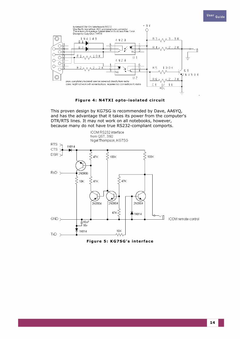
There are even simpler designs available, such as this opto-isolated model by Gary Dion N4TXI:
Gary writes: "Being the paranoid type I decided to design my own electrically isolated version. I figure it would be preferred in a field day situation with questionable rig grounding.
The biggest challenge was powering the optos on the radio side. The 8v line coming from the 706 can source at most 10 mA (per spec). This design pulls an average of less than 0.5 mA. The power supply can be taken from either the ACC connector or the microphone jack. Many isolated audio interface designs already exist, so I decided not to include that on the schematic".
U s e r G u i d e
14
Figure 4: N4TXI opto-isolated circuit
This proven design by KG7SG is recommended by Dave, AA6YQ, and has the advantage that it takes its power from the computer's DTR/RTS lines. It may not work on all notebooks, however, because many do not have true RS232-compliant comports.
Figure 5: KG7SG's interface
U s e r G u i d e
15
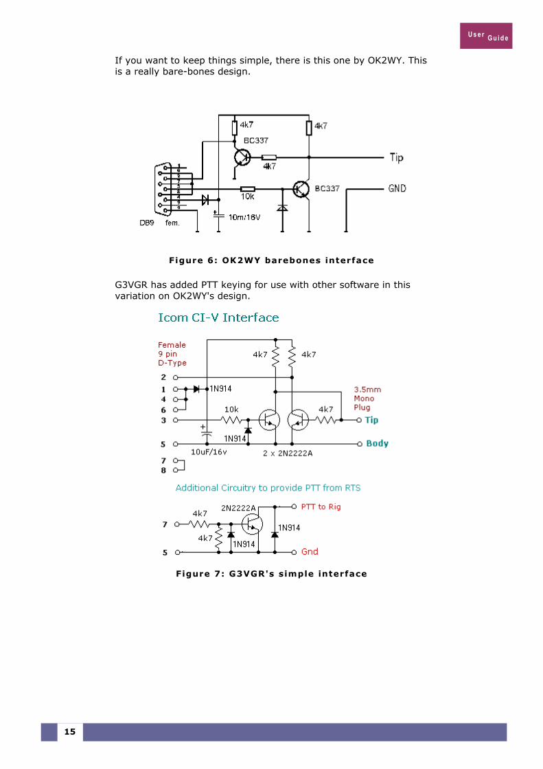
If you want to keep things simple, there is this one by OK2WY. This is a really bare-bones design.
Figure 6: OK2WY barebones interface
G3VGR has added PTT keying for use with other software in this variation on OK2WY's design.
Figure 7: G3VGR's simple interface
U s e r G u i d e
16
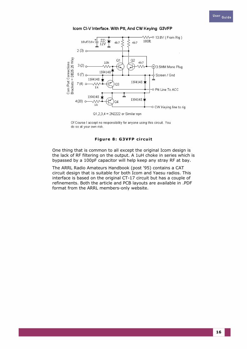
Figure 8: G3VFP circuit
One thing that is common to all except the original Icom design is the lack of RF filtering on the output. A 1uH choke in series which is bypassed by a 100pF capacitor will help keep any stray RF at bay.
The ARRL Radio Amateurs Handbook (post '95) contains a CAT circuit design that is suitable for both Icom and Yaesu radios. This interface is based on the original CT-17 circuit but has a couple of refinements. Both the article and PCB layouts are available in .PDF format from the ARRL members-only website.
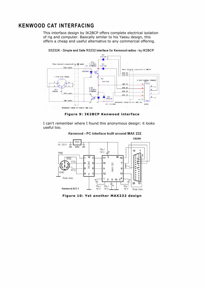
KENWOOD CAT INTERFACING This interface design by IK2BCP offers complete electrical isolation of rig and computer. Basically similar to his Yaesu design, this offers a cheap and useful alternative to any commercial offering.
Figure 9: IK2BCP Kenwood interface
I can’t remember where I found this anonymous design: it looks useful too.
Figure 10: Yet another MAX232 design

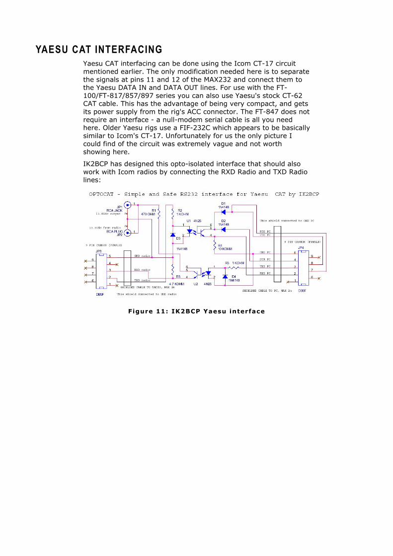
YAESU CAT INTERFACING Yaesu CAT interfacing can be done using the Icom CT-17 circuit mentioned earlier. The only modification needed here is to separate the signals at pins 11 and 12 of the MAX232 and connect them to the Yaesu DATA IN and DATA OUT lines. For use with the FT-100/FT-817/857/897 series you can also use Yaesu's stock CT-62 CAT cable. This has the advantage of being very compact, and gets its power supply from the rig's ACC connector. The FT-847 does not require an interface - a null-modem serial cable is all you need here. Older Yaesu rigs use a FIF-232C which appears to be basically similar to Icom's CT-17. Unfortunately for us the only picture I could find of the circuit was extremely vague and not worth showing here.
IK2BCP has designed this opto-isolated interface that should also work with Icom radios by connecting the RXD Radio and TXD Radio lines:
Figure 11: IK2BCP Yaesu interface
U s e r G u i d e
20
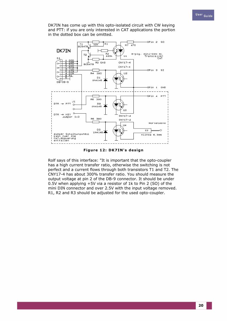
DK7IN has come up with this opto-isolated circuit with CW keying and PTT: if you are only interested in CAT applications the portion in the dotted box can be omitted.
Figure 12: DK7IN's design
Rolf says of this interface: "It is important that the opto-coupler has a high current transfer ratio, otherwise the switching is not perfect and a current flows through both transistors T1 and T2. The CNY17-4 has about 300% transfer ratio. You should measure the output voltage at pin 2 of the DB-9 connector. It should be under 0.5V when applying +5V via a resistor of 1k to Pin 2 (SO) of the mini DIN connector and over 2.5V with the input voltage removed. R1, R2 and R3 should be adjusted for the used opto-coupler.
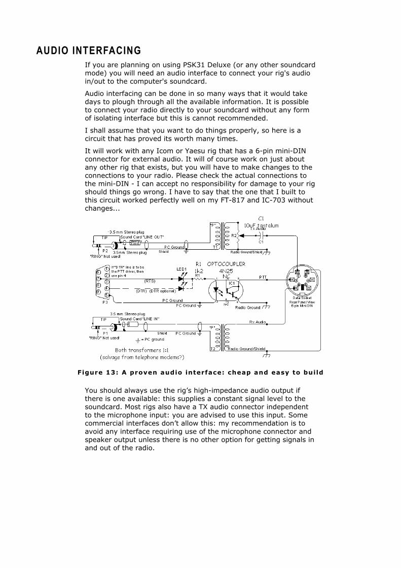
AUDIO INTERFACING If you are planning on using PSK31 Deluxe (or any other soundcard mode) you will need an audio interface to connect your rig's audio in/out to the computer's soundcard.
Audio interfacing can be done in so many ways that it would take days to plough through all the available information. It is possible to connect your radio directly to your soundcard without any form of isolating interface but this is cannot recommended.
I shall assume that you want to do things properly, so here is a circuit that has proved its worth many times.
It will work with any Icom or Yaesu rig that has a 6-pin mini-DIN connector for external audio. It will of course work on just about any other rig that exists, but you will have to make changes to the connections to your radio. Please check the actual connections to the mini-DIN - I can accept no responsibility for damage to your rig should things go wrong. I have to say that the one that I built to this circuit worked perfectly well on my FT-817 and IC-703 without changes...
Figure 13: A proven audio interface: cheap and easy to build
You should always use the rig’s high-impedance audio output if there is one available: this supplies a constant signal level to the soundcard. Most rigs also have a TX audio connector independent to the microphone input: you are advised to use this input. Some commercial interfaces don’t allow this: my recommendation is to avoid any interface requiring use of the microphone connector and speaker output unless there is no other option for getting signals in and out of the radio.

COMMERCIAL SOLUTIONS
CAT INTERFACE The CAT interface is used by Ham Radio Deluxe to connect to your rig and control the frequency, mode etc.
There's no point in beating about the bush: if you plan to purchase a ready-made Icom CT-17 or Yaesu CT-62, go for it. There are alternatives, though, and they range in price from very competitive to downright expensive. It's impossible to include all suppliers - I suggest that you do a quick search using Google with the strings "YAESU CAT control" and "ICOM CI-V cables"
Neil – G4ZLP – can offer inexpensive CAT interfaces for Icom and Yaesu radios. I have tested one of these and found it to be perfectly acceptable. You can find more details on the Ham Radio Deluxe User Community Forums at http://www.ham-radio.ch/forums
HB9DRV's software is developed with standard interfaces and cables, but every possible attempt will be made to support homemade cables. You will not go wrong if you purchase your cables from the rig manufacturer.
AUDIO INTERFACE You need an audio (soundcard) interface for PSK31 Deluxe to connect your rig's audio in/out to the computer's soundcard.
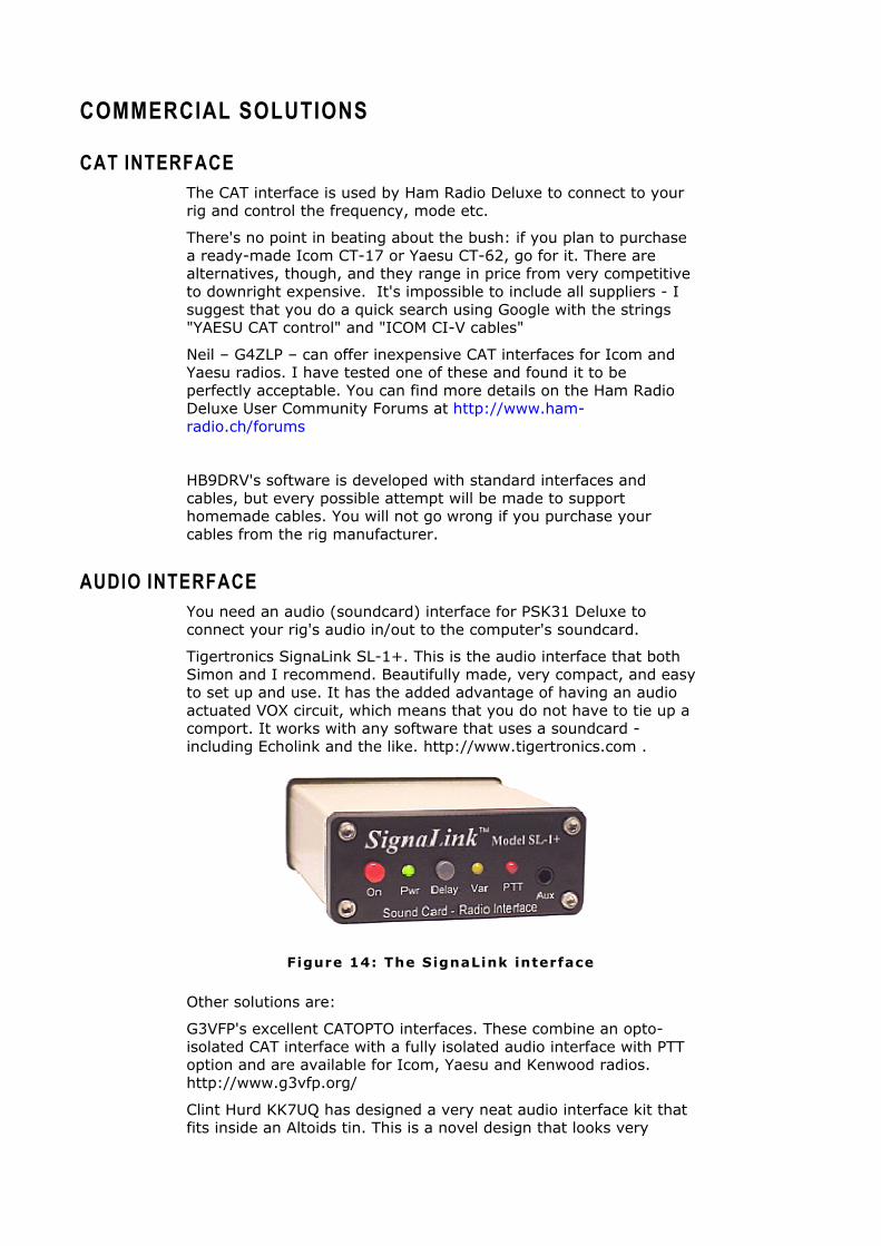
Tigertronics SignaLink SL-1+. This is the audio interface that both Simon and I recommend. Beautifully made, very compact, and easy to set up and use. It has the added advantage of having an audio actuated VOX circuit, which means that you do not have to tie up a comport. It works with any software that uses a soundcard - including Echolink and the like. http://www.tigertronics.com .
Figure 14: The SignaLink interface
Other solutions are:
G3VFP's excellent CATOPTO interfaces. These combine an opto-isolated CAT interface with a fully isolated audio interface with PTT option and are available for Icom, Yaesu and Kenwood radios. http://www.g3vfp.org/
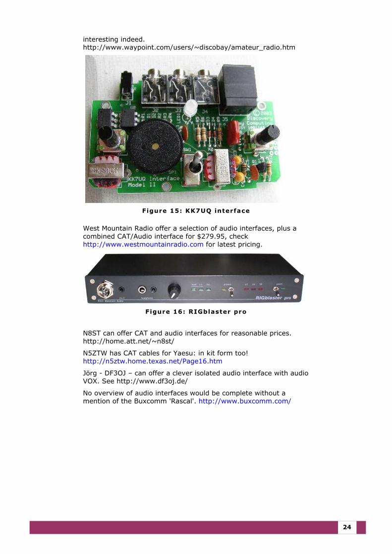
Clint Hurd KK7UQ has designed a very neat audio interface kit that fits inside an Altoids tin. This is a novel design that looks very
24
interesting indeed. http://www.waypoint.com/users/~discobay/amateur_radio.htm
Figure 15: KK7UQ interface
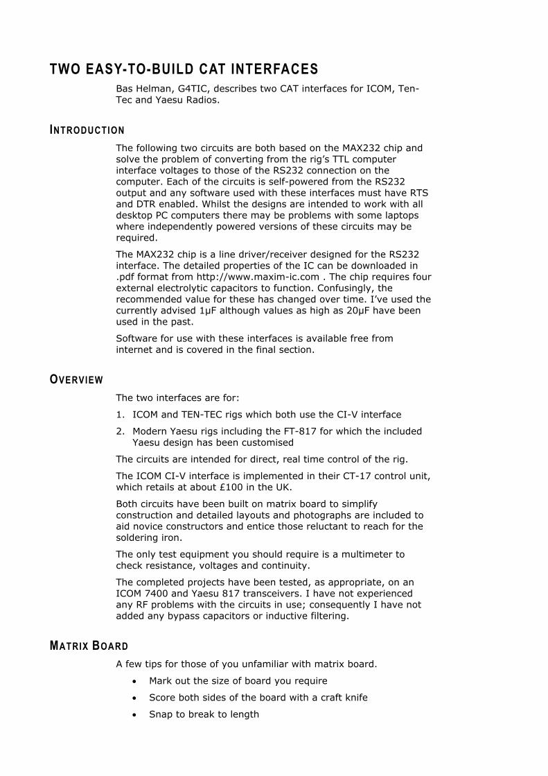
West Mountain Radio offer a selection of audio interfaces, plus a combined CAT/Audio interface for $279.95, check http://www.westmountainradio.com for latest pricing.
Figure 16: RIGblaster pro
N8ST can offer CAT and audio interfaces for reasonable prices. http://home.att.net/~n8st/
N5ZTW has CAT cables for Yaesu: in kit form too! http://n5ztw.home.texas.net/Page16.htm
Jörg - DF3OJ – can offer a clever isolated audio interface with audio VOX. See http://www.df3oj.de/
No overview of audio interfaces would be complete without a mention of the Buxcomm 'Rascal'. http://www.buxcomm.com/
TWO EASY-TO-BUILD CAT INTERFACES Bas Helman, G4TIC, describes two CAT interfaces for ICOM, Ten-Tec and Yaesu Radios.
INTRODUCTION The following two circuits are both based on the MAX232 chip and solve the problem of converting from the rig’s TTL computer interface voltages to those of the RS232 connection on the computer. Each of the circuits is self-powered from the RS232 output and any software used with these interfaces must have RTS and DTR enabled. Whilst the designs are intended to work with all desktop PC computers there may be problems with some laptops where independently powered versions of these circuits may be required.
The MAX232 chip is a line driver/receiver designed for the RS232 interface. The detailed properties of the IC can be downloaded in .pdf format from http://www.maxim-ic.com . The chip requires four external electrolytic capacitors to function. Confusingly, the recommended value for these has changed over time. I’ve used the currently advised 1µF although values as high as 20µF have been used in the past.
Software for use with these interfaces is available free from internet and is covered in the final section.
OVERVIEW The two interfaces are for:
1. ICOM and TEN-TEC rigs which both use the CI-V interface
2. Modern Yaesu rigs including the FT-817 for which the included Yaesu design has been customised
The circuits are intended for direct, real time control of the rig.
The ICOM CI-V interface is implemented in their CT-17 control unit, which retails at about £100 in the UK.
Both circuits have been built on matrix board to simplify construction and detailed layouts and photographs are included to aid novice constructors and entice those reluctant to reach for the soldering iron.
The only test equipment you should require is a multimeter to check resistance, voltages and continuity.
The completed projects have been tested, as appropriate, on an ICOM 7400 and Yaesu 817 transceivers. I have not experienced any RF problems with the circuits in use; consequently I have not added any bypass capacitors or inductive filtering.
MATRIX BOARD A few tips for those of you unfamiliar with matrix board.
• Mark out the size of board you require
• Score both sides of the board with a craft knife
• Snap to break to length
26
• Remove the rough edges with the knife or a file
• Before mounting any components clean the copper tracks with a BrilloPad and dry
The only specialist requirement for constructing with matrix board is a device for cutting the copper tracks. In the UK a spot face cutter is available from Maplin’s, at a price. Fortunately there are many convenient alternatives. A drill bit set into a piece of dowelling makes a very effective tool as do some reamers – check your Swiss army knife.
The usual order of construction is to start with the lowest profile components and work systematically to those of the highest profile. I found it easier to start by placing the pins and socket in order to define the key positions on the matrix. This makes it easier to locate and solder the links followed by the remaining components.
A soldering iron tip of 2.5mm is ideal for these projects.
CONSTRUCTION
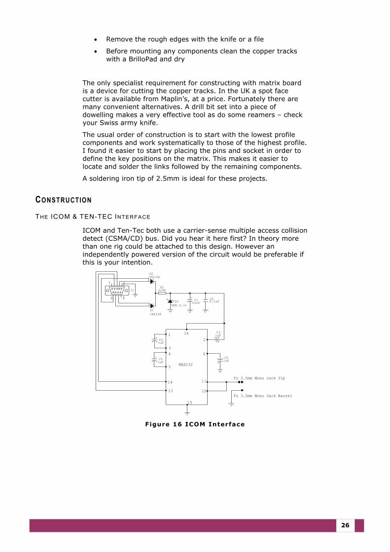
THE ICOM & TEN-TEC INTERFACE
ICOM and Ten-Tec both use a carrier-sense multiple access collision detect (CSMA/CD) bus. Did you hear it here first? In theory more than one rig could be attached to this design. However an independently powered version of the circuit would be preferable if this is your intention.
To 3.5mm Mono Jack Barrel
To 3.5mm Mono Jack Tip
96
51
14
13
15
12
11
6
21
34
5
16
MAX232 +
C61uF
+
C51uF
+
C41uF
+
C31uF
C20.1uF
+
C110uFD3
ZEN 4.7v
D21N4148
D11N4148
J1R1
220R
Figure 16 ICOM Interface
U s e r G u i d e
27
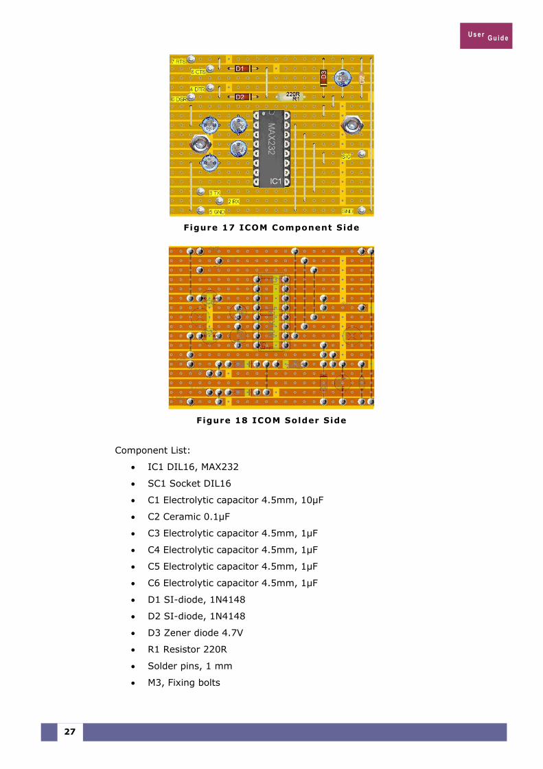
Figure 17 ICOM Component Side
Figure 18 ICOM Solder Side
Component List:
• IC1 DIL16, MAX232
• SC1 Socket DIL16
• C1 Electrolytic capacitor 4.5mm, 10µF
• C2 Ceramic 0.1µF
• C3 Electrolytic capacitor 4.5mm, 1µF
• C4 Electrolytic capacitor 4.5mm, 1µF
• C5 Electrolytic capacitor 4.5mm, 1µF
• C6 Electrolytic capacitor 4.5mm, 1µF
• D1 SI-diode, 1N4148
• D2 SI-diode, 1N4148
• D3 Zener diode 4.7V
• R1 Resistor 220R
• Solder pins, 1 mm
• M3, Fixing bolts
28
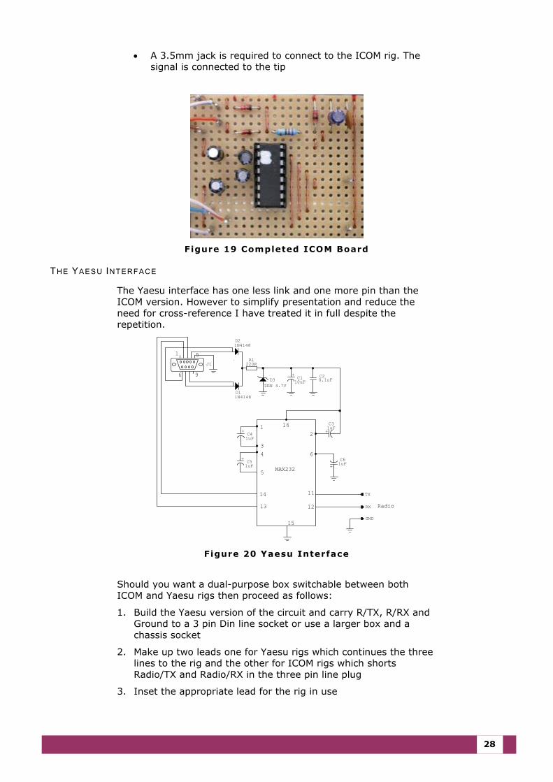
• A 3.5mm jack is required to connect to the ICOM rig. The signal is connected to the tip
Figure 19 Completed ICOM Board
THE YAESU INTERFACE
The Yaesu interface has one less link and one more pin than the ICOM version. However to simplify presentation and reduce the need for cross-reference I have treated it in full despite the repetition.
Radio
MAX232
16
5
43
12
6
11
12
15
13
14
1 5
6 9
RX
TX
GND
+
C61uF
+
C51uF
+
C41uF
+
C31uF
C20.1uF
+
C110uFD3
ZEN 4.7V
D21N4148
D11N4148
J1R1
220R
Figure 20 Yaesu Interface
Should you want a dual-purpose box switchable between both ICOM and Yaesu rigs then proceed as follows:
1. Build the Yaesu version of the circuit and carry R/TX, R/RX and Ground to a 3 pin Din line socket or use a larger box and a chassis socket
2. Make up two leads one for Yaesu rigs which continues the three lines to the rig and the other for ICOM rigs which shorts Radio/TX and Radio/RX in the three pin line plug
3. Inset the appropriate lead for the rig in use
U s e r G u i d e
29
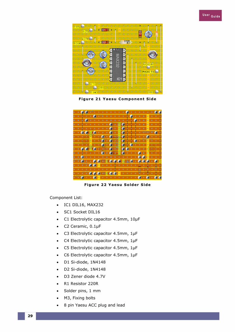
Figure 21 Yaesu Component Side
Figure 22 Yaesu Solder Side
Component List:
• IC1 DIL16, MAX232
• SC1 Socket DIL16
• C1 Electrolytic capacitor 4.5mm, 10µF
• C2 Ceramic, 0.1µF
• C3 Electrolytic capacitor 4.5mm, 1µF
• C4 Electrolytic capacitor 4.5mm, 1µF
• C5 Electrolytic capacitor 4.5mm, 1µF
• C6 Electrolytic capacitor 4.5mm, 1µF
• D1 Si-diode, 1N4148
• D2 Si-diode, 1N4148
• D3 Zener diode 4.7V
• R1 Resistor 220R
• Solder pins, 1 mm
• M3, Fixing bolts
• 8 pin Yaesu ACC plug and lead
30
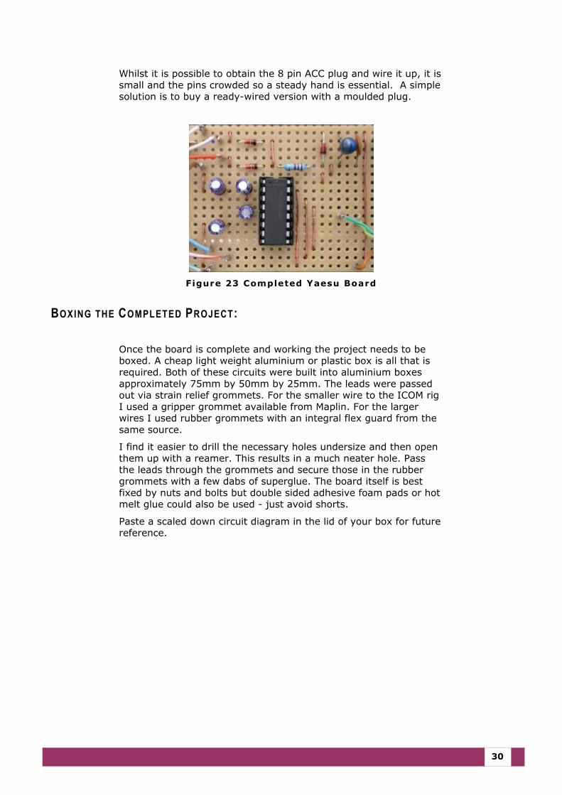
Whilst it is possible to obtain the 8 pin ACC plug and wire it up, it is small and the pins crowded so a steady hand is essential. A simple solution is to buy a ready-wired version with a moulded plug.
Figure 23 Completed Yaesu Board
BOXING THE COMPLETED PROJECT:
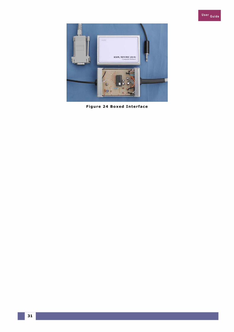
Once the board is complete and working the project needs to be boxed. A cheap light weight aluminium or plastic box is all that is required. Both of these circuits were built into aluminium boxes approximately 75mm by 50mm by 25mm. The leads were passed out via strain relief grommets. For the smaller wire to the ICOM rig I used a gripper grommet available from Maplin. For the larger wires I used rubber grommets with an integral flex guard from the same source.
I find it easier to drill the necessary holes undersize and then open them up with a reamer. This results in a much neater hole. Pass the leads through the grommets and secure those in the rubber grommets with a few dabs of superglue. The board itself is best fixed by nuts and bolts but double sided adhesive foam pads or hot melt glue could also be used - just avoid shorts.
Paste a scaled down circuit diagram in the lid of your box for future reference.
U s e r G u i d e
31
Figure 24 Boxed Interface