Castel Belasi’s special underpinning and reinforcement project
8
1 HISTORICAL AND GEOGRAPHICAL SETTING Castel Belasi stands in a strategic position that overlooks a probably Roman-origin road at the entrance between the Adige Valley and the Non Valley. This was once the only access to the areas beyond the Alps and to the southern lands of Figure 1. Map of Italy and position of Campodenno. Europe (Fig. 1). Following the on-site surveys and the researches on its history and on the building techniques and typologies (Faganello & Festi 1993, Grofer 1967a, Grofer 1967b, Tabarelli 1989), it was possible to obtain quite a clear idea of the appearance of this fortified complex, as well as its layout and its construction stages in order to understand its spatial design throughout the centuries. The exact date of its foundation is not known, but it was probably in the 12 th century. Some believe that originally it was a volksburg, that is a fortified enclosure where the population could find refuge in case of danger. And that afterwards it was only used for military purposes with the likely encroachment of the community’s rights. It provides one of the best examples of a castle with a continuous evolution. From the original fortified complex, that probably consisted of a simple enclosure with a central keep, to the residential castle, from the era of its foundation until the 20 th century. Given the building materials used that cannot be found locally (granite) and the remarkably high walls, it is clear that this castle has always been a fortified site of a certain importance (Primerano 1989). The first interventions were carried out at the turn of the 15 th century and it started its gradual evolution into a noble residence. The entrance doors were built and the noble residence in the centre of the enclosure was created from the union of three different buildings: the pentagonal tower, a regular form construction to the north of the tower and a central body that connected these two structures (Fig. 3). The chapel was also Castel Belasi’s special underpinning and reinforcement project P. Mazzalai University of Padova, Italy S. Torresani, L. Silvestri, L. Springhetti SWS Engineering Spa, Trento, Italy ABSTRACT: This document provides a description of the structural recovery of the ancient complex known as “Castel Belasi”. The worsening of the cement binder of the perimetric walls, along with the creep of the slope on which the castle stands, has brought about visible instability with angular distortion and such an extensive crack pattern that the structural integrity of many walls is at risk. From the first on-site survey (cognition stage) the main reasons for this decay were analysed (analysis stage) and a series of interventions were drawn up (project stage) in order to stop the creep of the slope and to reinforce the wall base (under- foundations and underpinnings, even with micro-piles).
Transcript of Castel Belasi’s special underpinning and reinforcement project

1 HISTORICAL AND GEOGRAPHICAL SETTING
Castel Belasi stands in a strategic position that overlooks a probably Roman-origin road at the entrance between the Adige Valley and the Non Valley. This was once the only access to the areas beyond the Alps and to the southern lands of
Figure 1. Map of Italy and position of Campodenno.
Europe (Fig. 1). Following the on-site surveys and the researches on its history and on the building techniques and typologies (Faganello & Festi 1993, Grofer 1967a, Grofer 1967b, Tabarelli 1989), it was possible to obtain quite a clear idea of the appearance of this fortified complex, as well as its layout and its construction stages in order to understand its spatial design throughout the centuries.
The exact date of its foundation is not known, but it was probably in the 12th century. Some believe that originally it was a volksburg, that is a fortified enclosure where the population could find refuge in case of danger. And that afterwards it was only used for military purposes with the likely encroachment of the community’s rights.
It provides one of the best examples of a castle with a continuous evolution. From the original fortified complex, that probably consisted of a simple enclosure with a central keep, to the residential castle, from the era of its foundation until the 20th century. Given the building materials used that cannot be found locally (granite) and the remarkably high walls, it is clear that this castle has always been a fortified site of a certain importance (Primerano 1989). The first interventions were carried out at the turn of the 15th century and it started its gradual evolution into a noble residence. The entrance doors were built and the noble residence in the centre of the enclosure was created from the union of three different buildings: the pentagonal tower, a regular form construction to the north of the tower and a central body that connected these two structures (Fig. 3). The chapel was also
Castel Belasi’s special underpinning and reinforcement project
P. Mazzalai University of Padova, Italy
S. Torresani, L. Silvestri, L. Springhetti SWS Engineering Spa, Trento, Italy
ABSTRACT: This document provides a description of the structural recovery of the ancient complex known as “Castel Belasi”. The worsening of the cement binder of the perimetric walls, along with the creep of the slope on which the castle stands, has brought about visible instability with angular distortion and such an extensive crack pattern that the structural integrity of many walls is at risk. From the first on-site survey (cognition stage) the main reasons for this decay were analysed (analysis stage) and a series of interventions were drawn up (project stage) in order to stop the creep of the slope and to reinforce the wall base (under-foundations and underpinnings, even with micro-piles).

Figure 2. Picture of Castel Belasi.
Figure 3. Castle’s layout. (1)Guardhouse; (2) Supporting wall by the entrance (southern side); (3) Suppoting wall (eastern side); (4) Custodian’s lodge; (5) The castle – northern block; (6) The castle – southern block; (7) The castle – central block.
probably built or renovated in the 16th century. It was dedicated to San Martino of Tours and was located in the noble court to the western side of the tower (Weber 1992).
Many other interventions were carried out in the 17th century and this was probably when the castle acquired its final appearance. While in the 19th century its gradual decay started (Perogalli & Prato 1987). In 1940 the castle was in a poor state of neglect, and around 1950 it was even further ruined by various acts of vandalism.
In 2000 the Municipality of Campodenno bought the whole property with the aim of recuperating the castle’s structural, cultural, artistic and historical integrity.
2 COGNITION STAGE (PRELIMINARY TO THE PLANNING)
2.1 Surveys before the planning
With respect to the project for the structural recovery, the first survey to evaluate the present conditions of the construction and its interaction with the soil foundation were carried out in 1993. It consisted of a plano-volumetric study of the building complex, a geological analysis of the area, geognostic investigations and the installation of mechanical crackmeters to monitor the evolution of cracking in the castle walls. (Design has been done by ATI: SWS Engineering Spa – Trento, prof. Cristinelli – Venezia and arch. Fochesato – Vicenza).
The survey falls into the thematic cartography of the P.U.P. (local development plan) concerning areas subject to geological control showing serious or medium problems. The geological and geognostic surveys followed these stages: a) detailed geological survey; b) definition of the hydrological and hydrogeological parameters with the aid of piezometers in boreholes; c) geognostic investigation (four drillings) with SCPT hole tests and undisturbed and semi-disturbed samples; d) stratigraphic survey; e) definition of the geo-mechanical parameters.
This survey has highlighted the following stratigraphic situation of the area: a) in contact with the foundations, layer of gravels and sand with modest fine fraction (thickness 3-8 m and quite high shear resistance); b) silty-clay layer hazel-grey colour, slightly overconsolidated (thickness 5-12 m; Nspt = 18-21-36-44); c) hard basement made of sandstone on a slightly sloping plane (depth 8-20 m).
2.2 Supplemental surveys provided throughout the planning
To limit the reinforcement interventions, both of the slope and the castle structure, other surveys have been planned to monitor their movements over a period of time. This will provide a useful yardstick of the situation before the intervention, during the reinforcement works and after their completion.
The following equipment will be employed for the monitoring: a) electric load cells positioned on the head of the permanent anchors to reinforce the slope; b) uni and biaxial wall clinometers strategically positioned in the building; c) electrical crackmeters strategically positioned in the building to be defined during the executive stage; d)

inclinometer casing; e) vibrating wire piezometers; f) rain gauge; g) data acquisition unit (ADK-110) located in a central room. This will be connected to the peripherals (multiplexer) spread over the area to be monitored and can collect the signals sent by the installed equipment. The ADK-10 unit will be equipped with a GSM module and relative antenna to transmit the data to a Remote Centre consisting of a PC with modem that can transmit/receive the data via GSM from the Central Unit. Thanks to a monitoring management software installed in the Remote Centre PC it will be possible to run the ADK-10 and the remote peripherals, to program them and to identify the alarm thresholds for all parameters collected.
3 ANALYSIS STAGE: PRESENT CONDITIONS OF THE STRUCTURES, CRACKING DEGREE REGISTERED ON-SITE AND REASONS FOR THE DECAY
The detailed survey of the castle has highlighted a high cracking degree with prevailing concentrations in certain areas. Moreover, there are various movements (shifts and rotations) in the constructions annexed to the castle such as the entrance (guardhouse to the south), custodian’s lodge to the west and the walls to contain the embankments to the south and east. The major cracking and instability phenomena relative to each structure of Castel Belasi are presented hereunder.
1) Guardhouse. Located in the south-eastern side between the access path and the present entrance to the castle. The analysis of the present conditions shows an extensive distribution of cracks, some even quite wide, mainly due to the wall shifting towards the valley.
The thrust exercised by the embankment behind the house itself may have contributed to the actual situation. The present cracking degree is probably in continuous evolution; in particular, the existence of an old steel anchor in the northern facade of the building underlines the fact that its movement towards the valley started some decades ago. The main reasons for this instability could include the active thrust of the soil behind the wall, the creep of the slope and the foundation under-sizing.
2) Supporting wall by the entrance (southern side). The wall clearly appears to be rotated towards the valley. In particular, in the most deformed part the height is 4.30 m with a value of differential horizontal displacement of 0.71 m, a remarkable value if compared to the height. Moreover, the wall has no foundation and the basement of the wall is approx. 0.70 m under the ground level. Longitudinally the wall shows vertical cracks from top to base, even quite wide, and some stone fragments have come off. The wall looks washed out
since there is no fixing mortar in places (Fig. 4). The instability may have resulted from: the active thrust of the soil behind the wall, the creep of the slope and the under-sizing of the wall foundations and of the wall itself.
3) Supporting wall (eastern side). The road leading to the present entrance to the castle lies on an embankment backed by a supporting wall facing the valley. This has a very unstable static balance, especially in the final section towards the north.
In fact, the wall front is completely detached from the rear part and roto-translated towards the valley. There are some large vertical cracks. The wall looks washed out since there is no fixing mortar in places. On the northern corner of the wall there are some cracks with an inclination of 45° and a width of around 10 cm. These show that the wall corner is gradually becoming detached and rotating towards the valley. The instability may have resulted from: the thrust of the soil behind the wall, the creep of the slope and the under-sizing of the wall foundations and of the wall itself.
4) Custodian’s lodge. Located next to the walls in the south-western side. It extends mainly vertically. Looking at the junction between the lodge and the castle walls, it is clear that the lodge is gradually becoming detached and rotating towards the valley (western direction). Moreover, there are many cracks where the shear stresses are higher. Possible causes of the instability: the creep of the slope and the under-sizing of the wall foundations.
5) The castle: northern block. In the northern perimetric walls the castle shows more serious and numerous damages that can jeopardize its future stability, especially in the north-western section. In fact, the outer wall is detached from the central body, especially near the north-western corner, and is probably still bound to the building only thanks to the horizontal trusses. The vaults on the first level are clearly separated from the perimetric wall.
Figure 4. Supporting wall by the entrance. The wall clearly
appears to be rotated towards the valley.
On the north-eastern wall there are sections where the masonry is washed out, probably due to water leaks caused by the bad conditions of the wall tops. The instability may have resulted from: the under-sizing of the wall foundations; the differential settlements and the creep of the slope.
6) The castle: southern block. There are many wide vertical damages, especially near the south-western corner. Here there is a wide vertical crack on the outer perimetric wall with a corresponding internal crack showing that the western wall is becoming detached from the central body. There are other vertical cracks also where the perpendicular walls join the main walls. Moreover, there are also cracks in the entrance arch of the southern block (entrance door in the northern facade) with the stress path and cracks resulting from the horizontal movement of the western wall. These cracks have an inclination of 30° with reference to the vertical, thus clearly identifying the arch stress path. Possible causes of the instability: under-sizing of the wall foundations and differential settlements.
7) The castle: central block. This is the least damaged part of the whole complex. The pentagonal tower has a very rigid structure that exerts strong pressure on the soil, near the maximum bearing capacity. The cracking degree is not particularly significant.
4 PLANNING STAGE
4.1 Criteria and techniques for the intervention and reinforcement
The decision of whether to intervene and with what reinforcement criteria must derive from the analysis of the problem, as indicated in the previous paragraph. Afterwards, the methods employed for the structural reinforcement of the wall foundations (underpinning), of the castle walls (underpinning and under-foundations), of the supporting walls (straightening) and of the guardhouse (hoisting) will be indicated. In addition, the best intervention to improve the slope stability that is currently undergoing creeping phenomena will be decided.
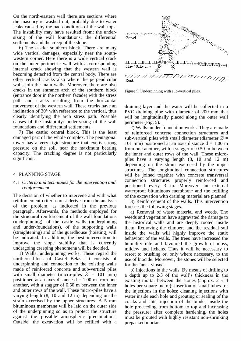
1) Walls: underpinning works. These regard the northern block of Castel Belasi. It consists of underpinning and connection to the existing walls made of reinforced concrete and sub-vertical piles with small diameter (micro-piles = 101 mm) positioned at an axes distance d = 1.00 m from one another, with a stagger of 0.50 m between the inner and outer rows of the wall. These micro-piles have a varying length (8, 10 and 12 m) depending on the strain exercised by the upper structures. A 5 mm bituminous membrane will be laid on the outer side of the underpinning so as to protect the structure against the possible atmospheric precipitations. Outside, the excavation will be refilled with a
Figure 5. Underpinning with sub-vertical piles.
draining layer and the water will be collected in a PVC draining pipe with diameter of 200 mm that will be longitudinally placed along the outer wall perimeter (Fig. 5).
2) Walls: under-foundation works. They are made of reinforced concrete connection structures and sub-vertical piles with small diameter (diameter = 101 mm) positioned at an axes distance d = 1.00 m from one another, with a stagger of 0.50 m between the inner and outer rows of the wall. These micro-piles have a varying length (8, 10 and 12 m) depending on the strain exercised by the upper structures. The longitudinal connection structures will be joined together with concrete transversal connection structures properly reinforced and positioned every 3 m. Moreover, an external waterproof bituminous membrane and the refilling of the excavation with draining material are planned.
3) Reinforcement of the walls. This intervention foresees the following stages.
a) Removal of waste material and weeds. The weeds and vegetation have aggravated the damage to the historical walls and are deeply rooted inside them. Removing the climbers and the residual soil inside the walls will highly improve the static behaviour of the walls. The trees have increased the humidity rate and favoured the growth of moss, mildew and lichens. Thus it will be necessary to resort to brushing or, only where necessary, to the use of biocide. Moreover, the stones will be selected for the “anastylosis”.
b) Injections in the walls. By means of drilling to a depth up to 2/3 of the wall’s thickness in the existing mortar between the stones (approx. 2 4 holes per square metre); insertion of small tubes for the injections in the holes; cleaning injections with water inside each hole and grouting or sealing of the cracks and slits; injection of the binder inside the hole proceeding from bottom to top and increasing the pressure; after complete hardening, the holes must be grouted with highly resistant non-shrinking prepacked mortar.

c) Restoration of cracks and slits. This entails thorough cleaning of the slits and subsequent injection of epoxy resin under pressure.
d) Partial integrations through “anastylosis”. This stage entails the partial reconstruction of the remains left on-site and properly restored. It foresees the use of slaked lime mortar; the mortar injected between the stone bricks will consist of powdered stone and lime.
e) Finishing of the wall tops. A simple cover is foreseen, made of mortar and laid following the natural shape of the stones upper sides. This will give the structure a protection against the atmospheric agents that can damage the mortar due to the running of the meteoric waters.
4) Straightening of the entrance wall. The rotation of the supporting wall shows that the strain of the soil behind it is too high with respect to its dimensions and characteristics. In order to regain the safety conditions and to preserve the wall features, it is necessary to reinforce the wall by straightening it after removing the soil behind the wall itself (Fig. 6). The stages foreseen for the straightening intervention are described hereunder:
- Stage 1: Excavation behind the wall to place the anchors. Setting and installation of the hoisting device after preparing the concrete basements with dimensions 60120 cm to enlarge the foundation basement; positioning of the steel bars or the connecting plates and of the hydraulic jacks needed to straighten the wall;
- Stage 2: hoisting of the containing wall with double-effect jacks (max capacity foreseen 70 tons) through cyclic feed and distribution. The hoisting will be performed through various phases. In this stage the two rows of anchors will also be placed.
- Stage 3: this stage entails the refilling behind the wall with draining material and the tensioning of the anchors. Disassembling of the hoisting metallic structure and the hydraulic jacks.
The characteristics of the hoisting equipment are described hereunder: a) jacks with total extension of 500 mm, with piston and carter made of highly-resistant steel, with double effect, maximum pressure of 600 bars and maximum capacity of 70 tons; b) oil-hydraulic power unit consisting of the distribution system of the pressure oil that comprises the solenoid valves, a rubber pipe to transport the high-pressure fluids with double-spiral braided reinforcement resistant up to 800 bars, with varying length and connected to the pressure readout data logger and to the joint placed inside the jacks; with interposed safety valve for the high pressures; c) 20 HP electric motor, 50 l tank and pump with pistons with proper capacity for the maximum number of connected jacks; d) pressure chambers with diameter 150 mm, stroke length 500 mm, and maximum capacity 70 tons, through cyclic feed and distribution.
Figure 6. Straightening of the entrance wall. Hoisting of the containing wall with double-effect jacks.
After completing the consolidation, the reinforced concrete connection structure to enlarge the foundation basement will be adequately covered so that it cannot be seen from the road leading to the castle entrance.
5) Hoisting of the guardhouse. This intervention
entails the removal of the soil inside the guardhouse
to expose the current foundation basement. The
building of a 50 cm reinforced concrete slab and a
rigid connection structure on three sides of the house
(north, south and east) with 60120 cm dimensions
is planned. The slab and connection structures will
be anchored to the walls with the use of HE profile
steel passing structural shape placed before casting
the concrete. The guide pipes to insert the SOLES
tubular piles will also be inserted into the connection
structure and slab; each pile will be connected to an
oil-hydraulic unit so as to monitor the single load
while hoisting. Once the hoisting is over, the load on
the foundations will be transmitted from the rigid
reinforced concrete structure to the SOLES piles.
This operation will recuperate the uprightness of the
guardhouse. Finally, the slab and connection
structure will be covered with earth again so as to
minimize the impact of the intervention.
6) Reinforcement works of the slope (Fig. 7). The
plan includes the construction of a system of micro-
piles (vertical and sub-vertical) that are connected at
the top to a rigid reinforced concrete constraint
structure where the permanent anchors find
resistance. In the south-east side the reinforcement
structure will be placed just next to the perimetric
wall of the access road, while elsewhere it will be in
the northern side at about 10 m from the castle walls.

Figure 7. Reinforcement of the slope.
Both vertical and sub-vertical micro-piles will have
a hole diameter of 220 mm and a length varying
from 9 to 15 m depending on their placement. The
reinforcement consists of a steel pipe with diameter
of 127 mm and thickness of 10 mm. Longitudinally
the micro-piles will be placed every 1.20 m and the
rows will be evenly staggered between the vertical
and sub-vertical piles. The anchors will be active
and permanent; in each hole with diameter of 180
mm there will be inserted 5 strands with diameter
0.6” and they will be repeatedly and selectively
injected. Longitudinally, the anchors axes distance
will be 2.40 m (Fig. 7). This kind of structure
provides the following advantages: a) it is a draining
structure, thus it does not hamper the natural flow of
the seepage waters avoiding hazardous deposit
and/or stagnations; b) this structure can improve
both the local foundation stability (lateral
confinement effect) and the global stability of the
work; c) these micro-piles, that are properly
connected to the reinforced concrete rigid
connection structure, also work as a supporting
structure against the possible stability problems due
to its creeping towards the valley; d) the use of
permanent anchors (pre-tensioned) will render the
whole structure more reactive, which means that it
will be able to give stability even with slight
movements; e) the micro-piles technology well suits
the soil characteristics: in fact, it permits drilling
with limited vibrations that would otherwise damage
the building and the perimetric walls. In the more
compact areas it is possible to resort to rotary
percussion drilling with a feed down-hole hammer. To sum up, this is the ideal structure to counteract
the possible instability of the slope. This reinforcement can be modelled with finite element method (FEM) as illustrated in the following paragraph.
4.2 Methods of analysis, modelling and control of the planning hypothesis: application to the works to reinforce the slope
The “FLAC” programme has been used for the numeric analysis of the slope behaviour and to design the reinforcement intervention. The geotechnical characterization adopted is as follows (Fig. 8).
a) Layer 1: Gravels and sand. For the granulometry, see the description provided by the drillings. These show that it mainly consists of cemented sandy gravel. With respect to the weight of the unit of volume, the value is about 19 kN/m3. It must be considered that it is a medium- to thickened material. Three dynamic standard penetration tests SPT have been performed on this layer, two of them until refusal (Nspt = 100) and one provided a value Nspt = 38 at the depth of 4 ÷ 5 m.
Taking into account the effective vertical tension or the average tension, it is possible to define the specific gravity values of the deposit on the basis of the correlations provided by the literature (Jamiolkowski et al. 1979, Lancellotta 1987, NAVFAC 1982, Terzaghi et al. 1948). In particular, using Skempton’s relation (1986) values SG > 80% are obtained. Once the SG is known, the angle of shear resistance (’) can be assessed through the SPT tests on the basis of Schmertmann’s method (1977) with values higher than 40°. For planning purposes, we can consider a precautionary angle of shear resistance ’ = 40°.
The gravelly structure has a sandy matrix with a good cementation degree. This resistance contribution is difficult to assess; for planning purposes, an effective cohesion should fall in the range c’ = 5 ÷ 15 kPa.
This module can be assessed on the basis of the correlations provided by the literature between the
Figure 8. The geotechnical characterization adopted in the “FLAC” programme for numeric analysis. Layer 1: gravel and sand; Layer 2: clay and silt; Layer 3: rigid rock.

Nspt and the elastic module. In this particular case we adopted the relation by D’Apollonia (Lancellotta 1987) for loose soils: E’ = 21.6 + 1.06 Nspt. Values with Nspt > 30 give module values higher than 50 MPa. Cautiously we adopt E’ = 40 MPa as minimum value of the deposit.
b) Layer 2: Clay and silt. For the granulometry, see the description provided by the drillings (Jamiolkowski et al. 1979). These show that it mainly consists of clay and silt. With respect to the weight for unit of volume, the value is about 19 kN/m3. It must be considered that it is a material with medium consistency. The Pocket-Penetrometer tests performed in the drillings have showed values comprised between 100 and 700 kPa. These values can be correlated to an undrained shear resistance cu = 50 ÷ 350 kPa. For the resistance parameters in drained soils, we can use the following values: effective cohesion c’ = 5 ÷ 15 kPa and angle of shear resistance ’ = 25 ÷ 28°.
First of all, it is necessary to survey the present situation (pre-intervention stage) so as to calibrate the underground model to be used for the calculations in planning the reinforcement intervention.
Figure 9. Calibration of underground model with back analysis of the resistance parameters (angle of shear resistance ’ considered constant). Output of “Flac” programme.
Figure 10. Analysis results: post-intervention stage. Output of “Flac” programme.
In this particular case, where the soils have both friction and cohesion (clay and silt, cemented sands and gravels), it was necessary to perform a back analysis (Fig. 9) of the resistance parameters and to consider reliable the values of the angles of shear resistance ’. The cohesion c’ is very difficult to assess and can be affected by the deposit structure. This parameter is defined through a sensitivity analysis to identify the value that gives the best interpretation of the average soil behaviour with respect to the problem under examination. In the calculation report, the castle perimetric wall has been considered by applying a load of 400 kN/m over a length of 2.0 m (pressure q = 200 kPa).
To sum up, the following shear resistance parameters have been calculated:
Layer 1 - Cemented gravels and sands. Effective cohesion c’ = 10 kPa; angle of shear resistance ’ = 40°.
Layer 2 - Clay and silt. Effective cohesion c’ = 10 kPa; angle of shear resistance ’ = 25°.
This provides a safety factor of the global stability equal to FS = 1.12 (pre-intervention safety factor), thus lower than the one set by the regulations in force.
Figure 10 summarized the analysis results. The stability is ensured mainly through the restraint exercised by the anchors (post-intervention stage). The anchors have been designed as cables that interact with the surrounding soil through resistant connection elements. Thus the cable is effectively anchored outside the stabilizing structure and gives stability by transferring the lateral skin friction over the length that falls into the potentially unstable soil. This hypothesis has been provided by the programme employed and is a good outline of the real mechanism. Differently from the calculation hypothesis, the first stretch of the anchor within the potential unstable structure is free (passive earth pressure zone) and the stabilizing effect is exercised by the reinforced concrete constraint structure. The anchor was defined with the following characteristics: maximum axial resistance Nlim = 1200 kN/m; b) longitudinal axes distance between the anchors d = 2.40 m; c) interface unit strength resistance referring to the nominal hole diameter Dp
= 180 mm equal to lim = 200 kPa. Cautiously, we did not take into account the flexional resistance contribution of the micro-piles.
The Figure 10 shows the results of the stability analysis after the intervention. The main results obtained are: post-intervention safety factor FS = 1.35 (>1.30); maximum axial thrust on the anchors with balance limit of the slope Nmax = 412 kN/m.

5 CONCLUSIONS
The approach adopted during the planning stages for the structural recovery of Castel Belasi permits: − the division of the interventions depending of the
urgency, the importance and the type of structure to reinforce;
− modular interventions and the possibility of carrying out further controls and works; to spread the intervention over a period of time depending on the monitoring of the subsidence of the structure and the slope.
− to reduce to the minimum the costs for the intervention by focusing only on the deteriorated areas and/or those about to deteriorate.
− to minimize the impact of the intervention from the environmental, landscape and artistic standpoint.
These needs can be met thanks to the numerical modelling. In this case, the major difficulty consists of collecting the parameters of the materials and interpreting the stress-strain events occurred throughout the years. The use of systems for a continuous acquisition of data can be very valuable in the planning stage.
REFERENCES
Faganello, F. & Festi, R. 1993. Castelli del Trentino. Ivrea: Priuli e Verlucca.
Gorfer, A. 1967a. I castelli del Trentino. Trento: Arti Grafiche Saturnia.
Gorfer, A. 1967b. Guida ai castelli del Trentino. Trento: Arca. Jamiolkowski, M., Lancellotta, R., Marchetti, S., Nova R. &
Pasqualini, E. 1979. Design Parameters for Soft Clays. Bringhton: SOA, VII ECSMFE.
Lancellotta, R. 1987. Geotecnica. Bologna: Zanichelli. NAVFAC DM 7.1. 1982. Soil Mechanics. Design Manual 7.1.
Dept of the Navy naval Facil. Engng. Command. Alexandria (USA).
Perogalli, C. & Prato, G.B. 1987. Castelli trentini nelle vedute di Johanna von Isser Grossrubatscher. Trento: Sezione Trentino dell’Istituto Italiano dei Castelli.
Primerano, D. 1989. Splendore d’Anaunia. Trento: Giovannini. Weber, S. 1992. Le chiese della valle di Non nella storia e
nell’arte. Mori: La Grafica Anastatica. Tabarelli, G.M. 1989. Guida ai castelli del Trentino. Trento:
Temi Editrice. Terzaghi, K., Peck, R.B. & Mesri, G. 1948. Soil Mechanics in
Engineering Practice. New York: J. Wiley & Sons.