Cast Inversion - ARANZ Medical · Cast Inversion 1 1 Introduction The Cast InversionTM feature for...
16
Cast Inversion TM for FastSCAN II TM March 2014 March 2014
Transcript of Cast Inversion - ARANZ Medical · Cast Inversion 1 1 Introduction The Cast InversionTM feature for...

Cast InversionTM
for FastSCAN IITM
March 2014
March 2014

Copyright c© 2005–2014 by Aranz Scanning Ltd
110 Papanui RoadMerivale, Christchurch, 8014New Zealand
PO Box 3894Christchurch, 8140New Zealand
www.aranz.comwww.fastscan.com
All rights reserved. No part of this publication may be reproduced, stored in a re-trieval system, or transmitted in any form or by any means—mechanical, photocopy-ing, recording or otherwise—without the prior written permission of ASL. No patentliability is assumed with respect to the use of the information contained herein. Whileevery precaution has been taken in the preparation of this manual, ASL assumes noresponsibility for errors or omissions. Neither is any liability assumed for damagesresulting from use of the information contained herein.
Cast InversionTM is a registered trademark of ASL.

Contents
1 Introduction 1
2 Overview 1
3 The Process 33.1 Preparation For Scanning . . . . . . . . . . . . . . . . . . . . . . . . . . 33.2 Scanning . . . . . . . . . . . . . . . . . . . . . . . . . . . . . . . . . . . . 6
3.2.1 Digitizing the Scanned Reference Marks . . . . . . . . . . . . . . 83.3 Applying Cast Inversion . . . . . . . . . . . . . . . . . . . . . . . . . . . 9
4 The Final Surface 12
5 Getting Help 13
Cast Inversion 1
1 Introduction
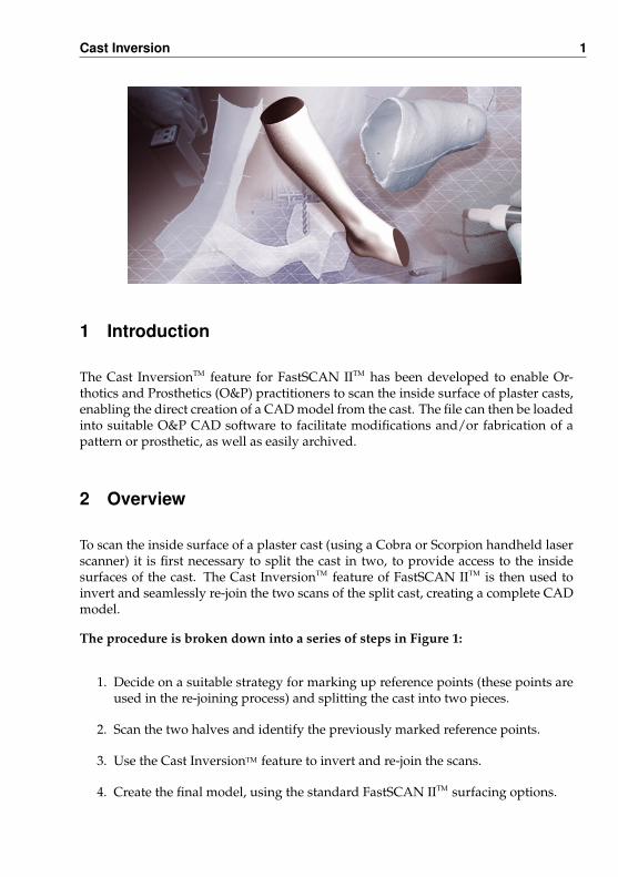
The Cast InversionTM feature for FastSCAN IITM has been developed to enable Or-thotics and Prosthetics (O&P) practitioners to scan the inside surface of plaster casts,enabling the direct creation of a CAD model from the cast. The file can then be loadedinto suitable O&P CAD software to facilitate modifications and/or fabrication of apattern or prosthetic, as well as easily archived.
2 Overview
To scan the inside surface of a plaster cast (using a Cobra or Scorpion handheld laserscanner) it is first necessary to split the cast in two, to provide access to the insidesurfaces of the cast. The Cast InversionTM feature of FastSCAN IITM is then used toinvert and seamlessly re-join the two scans of the split cast, creating a complete CADmodel.
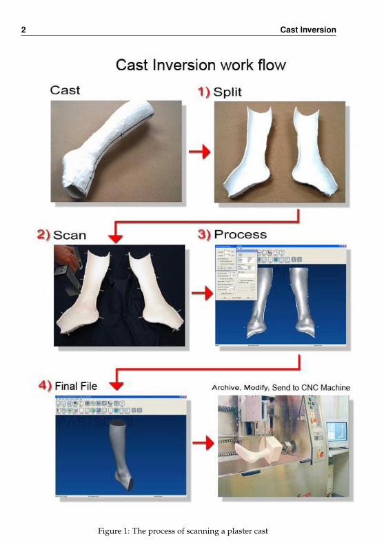
The procedure is broken down into a series of steps in Figure 1:
1. Decide on a suitable strategy for marking up reference points (these points areused in the re-joining process) and splitting the cast into two pieces.
2. Scan the two halves and identify the previously marked reference points.
3. Use the Cast InversionTM feature to invert and re-join the scans.
4. Create the final model, using the standard FastSCAN IITM surfacing options.
2 Cast Inversion
Figure 1: The process of scanning a plaster cast

Cast Inversion 3
3 The Process
3.1 Preparation For Scanning
1. Decide where best to split the cast and mark the path where the cut is to bemade. Generally the best results will be obtained by cutting the cast into twoapproximately equal pieces, in such a way as to allow maximum unimpededvisual access to the inside surfaces.
Figure 2: Vertical lines on the front of the cast.
2. Place a number of reference marks along the cutting path—these marks will beused later by the Cast InversionTM feature to assist in rejoining the two scannedsurfaces. The reference marks can easily be placed by drawing a number ofshort (20-50 mm long) lines perpendicular to the cutting path, with a part ofeach line remaining on either side of the cast after it is split in two. Typically sixto eight lines spaced around the full perimeter are sufficient (see Figures 2 & 3).

4 Cast Inversion
Figure 3: Vertical lines on the back of the cast.
3. The cast can now be cut (as cleanly as possible) along the previously definedcutting line. Any reduction in the cross section of the cast (due to saw bladethickness) can be compensated for later in the Cast InversionTM process. Toensure a high quality scan clean away any loose material from around the edgesof the cast.
Figure 4: The split cast.

Cast Inversion 5
4. The previously applied reference marks need to be highlighted so that they willappear on the scanned surface. This can be done in several ways:
• Method 1: Place thin strips of tape (2–3 mm wide and at least 15 mm long)on the edges of the split cast, directly above the reference marks, so that thetape sticks out (shown in Figure 5). The tape strips will be picked up duringthe scanning process and are easy to identify when processing the scans.
• Method 2: With thick walled casts simply continue the marker lines ontothe top surface of the walls of the split cast with a dark marker pen. Thelines will appear on the scan as a darkened area when Pseudo-Grayscale isenabled (by clicking View/Color Mapping/Pseudo-Grayscale).
Note: Some experimentation may by required to perfect this technique asdata must still be collected under the darkened areas.
• Method 3: Apply electronic markers using the Optical StylusTM (if avail-able).
Figure 5: Shows the split cast with tape markers placed on edges.

6 Cast Inversion
3.2 Scanning
1. Place the two halves of the cast side by side on a matte black cloth with theTransmitter placed between them, as shown in Figure 6.
Figure 6: The Transmitter between the two halves of the cast.
Note:
• The (matte) black cloth ensures that the surface of the table is not picked upduring the scanning process.
• It is useful to cover the Transmitter and cable with another black cloth orplace it directly under the main cloth (Figure 7).
• It is very important that neither the two parts of the cast or the Transmittermove during the scanning process (the cast halves may require some formof support to stop them rocking).
• Ensure that the table or surface on which the scanning takes place is non-metallic—a small wooden table is recommended.

Cast Inversion 7
Figure 7: Scanning the cast with the Transmitter covered.
2. Carefully scan the inside surface of both halves of the cast, including the topsurface of the rim and the markers. Take care not to scan the outside surfacesof the cast or any other unwanted objects within the scanner’s range (Figure 7).
3. The mechanical/optical stylus can now be used to digitize the reference mark-ers (the cast halves and reference transmitter must not be moved from theiroriginal positions). To use Mark With MouseTM to perform this function, seeSection 3.2.1
Figure 8: Scan aligned with the bounding box set to view.
8 Cast Inversion
3.2.1 Digitizing the Scanned Reference Marks
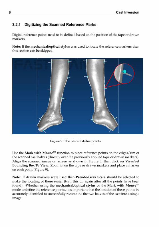
Digital reference points need to be defined based on the position of the tape or drawnmarkers.
Note: If the mechanical/optical stylus was used to locate the reference markers thenthis section can be skipped.
Figure 9: The placed stylus points.
Use the Mark with MouseTM function to place reference points on the edges/rim ofthe scanned cast halves (directly over the previously applied tape or drawn markers).Align the scanned image on screen as shown in Figure 8, then click on View/SetBounding Box To View. Zoom in on the tape or drawn markers and place a markeron each point (Figure 9).
Note: If drawn markers were used then Pseudo-Gray Scale should be selected tomake the locating of these easier (turn this off again after all the points have beenfound). Whether using the mechanical/optical stylus or the Mark with MouseTM
mode to define the reference points, it is important that the location of these points beaccurately identified to successfully recombine the two halves of the cast into a singleimage.

Cast Inversion 9
3.3 Applying Cast Inversion
1. Select Edit/Cast Inversion Mode to activate Cast InversionTM mode (a tick willappear next to it).
2. Select the Form Surface tab and click on Advanced (or Ctrl+G) to bring up theGenerate Surface dialog box (Figure 10). Enter the desired settings and clickApply (Basic Surface).
Note: The default parameters can be used as a starting point, however moresuitable settings to enter in the Generate Surface dialog for a typical Ankle-Foot Orthosis (AFO) might be:
Small Highly Detailed AFO Large AFOSmoothing 4.0 mm 10.0 mmDecimation 3.0 mm 6.0 mm
Limit Objects to: must remain on 2 and Surface Simplification is not required.
Figure 10: The Generate Surface dialog box with the Invert & Align button active.
10 Cast Inversion
3. If the Basic Surface looks satisfactory then save the file. The Invert & Alignbutton will become active (within the Generate Surface dialog).
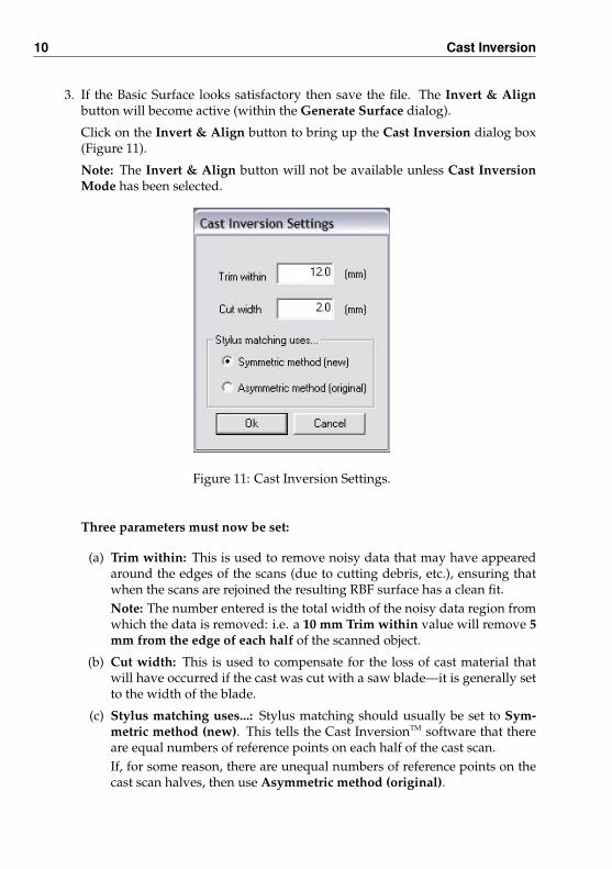
Click on the Invert & Align button to bring up the Cast Inversion dialog box(Figure 11).
Note: The Invert & Align button will not be available unless Cast InversionMode has been selected.
Figure 11: Cast Inversion Settings.
Three parameters must now be set:
(a) Trim within: This is used to remove noisy data that may have appearedaround the edges of the scans (due to cutting debris, etc.), ensuring thatwhen the scans are rejoined the resulting RBF surface has a clean fit.Note: The number entered is the total width of the noisy data region fromwhich the data is removed: i.e. a 10 mm Trim within value will remove 5mm from the edge of each half of the scanned object.
(b) Cut width: This is used to compensate for the loss of cast material thatwill have occurred if the cast was cut with a saw blade—it is generally setto the width of the blade.
(c) Stylus matching uses...: Stylus matching should usually be set to Sym-metric method (new). This tells the Cast InversionTM software that thereare equal numbers of reference points on each half of the cast scan.If, for some reason, there are unequal numbers of reference points on thecast scan halves, then use Asymmetric method (original).

Cast Inversion 11
4. Click the OK button to continue.
Any data in the set back area will now be removed and the scan adjusted forthe thickness of the saw blade (if required). Now orientate the scans as shownin Figure 12.
Figure 12: The object after Cast Inversion.

12 Cast Inversion
4 The Final Surface
Process the data using the RBF Surface Processing function within the Generate Sur-face dialog box (this should still be open) to produce the final surface.
Figure 13: The final RBF surface ready for exporting.
Note:
• Fit Accuracy should be between 0.3 mm (Small Highly Detailed AFO) and 0.5 mm(Large AFO).
• Mesh Resolution should be consistent with that of the Basic Surface: i.e. the deci-mation value should be the same as that used in the Basic Surface.
• If Trim to Edges is selected the Margin Size must be set to a larger value than thegap between the scans.
• The stylus points may be turned off to view a clean image. Click on Edit/StylusMarks List... (Ctrl+T) to bring up the Stylus Marks List dialog box (Figure 14).Select None or uncheck individual boxes in the list to view the object without the(selected) points.
Clicking on Invert will uncheck all checked stylus point boxes and check thosepreviously unchecked.
Left-clicking the mouse on a stylus number in the Stylus Marks List will turnthe selected point red. Choose more than one point by holding down Shift or

Cast Inversion 13
Figure 14: The Stylus Marks List dialog box.
Control while selecting points.
Note: Cast InversionTM is an optional feature of FastSCAN IITM and requires a separatelicense. The Cast InversionTM software also requires support from other licensed fea-tures of FastSCAN IITM: the optical/mechanical stylus (with the Mark with MouseTM
feature).
5 Getting Help
For help on any aspect of Cast InversionTM please email [email protected]


![FASTScan: A Fast Mobile Image Recognition SDK with Local ... · FASTScan: A Fast Mobile Image Recognition SDK with Local Database Using Convolutional Neural Network [1]Gamil Shamar,](https://static.fdocuments.in/doc/165x107/5e818afb6cd6c810ea6d45e3/fastscan-a-fast-mobile-image-recognition-sdk-with-local-fastscan-a-fast-mobile.jpg)