
CASHFLOW 126 AND 129 - Nordic Payment Solutions€¦ · · 2016-06-16the cashflow® 126 and 129...
56
The CASHFLOW ® 126 AND 129 4-WAY AND 8-WAY SELECTORS DESIGN GUIDE 26043 G3 709623001
Transcript of CASHFLOW 126 AND 129 - Nordic Payment Solutions€¦ · · 2016-06-16the cashflow® 126 and 129...

The
CASHFLOW® 126 AND 129
4-WAY AND 8-WAY SELECTORS
DESIGN GUIDE
26043 G3 709623001

Published by :
MEI
Internet: http://www.meigroup.com
For further information on issues in other languages please write to theTechnical Communications Manager at the above address.
CashFlow® 126 and CashFlow® 129 selectors Design Guide
© , MEI UK International Ltd., 1998. All rights reserved
Except as permitted under the relevant local legislation, no part of thispublication may be copied, transmitted, transcribed, or distributed in anyform or by any means, or stored in a database or retrieval system, ortranslated in any language (natural or computer), without the prior writtenpermission of MEI.
MEI®, CashFlow® and the MEI device are registered trademarks.©, MEI., 1998.
MEI reserves the right to change the product or the product specificationsat any time. While every effort has been made to ensure that the information in this publication is accurate, MEI disclaims any liability for any direct or indirect losses (howsoever caused) arising out of use or reliance on this information.
This document does not necessarily imply product availability.
Part number: 709623001
This edition (February 1998 ) Printed in the United Kingdom.
CashFlow® 126 and CashFlow® 129 selectors Design Guide
ii ©, MEI., 1998

12Parallel Mode . . . . . . . . . . . . . . . . . . . . . . . . . . . . . . . . . . . . . . . . . . . . . . . . . . . . . . . . . . . . . . . . . . . . . . . . . . .
12Introduction . . . . . . . . . . . . . . . . . . . . . . . . . . . . . . . . . . . . . . . . . . . . . . . . . . . . . . . . . . . . . . . . . . . . . . . . . . . . . .
12PRODUCT INTERFACES . . . . . . . . . . . . . . . . . . . . . . . . . . . . . . . . . . . . . . . . . . . . . . . . . . . . . . . . . . . . .
11Post-Gate Strobes . . . . . . . . . . . . . . . . . . . . . . . . . . . . . . . . . . . . . . . . . . . . . . . . . . . . . . . . . . . . . . . . . . . .
11Pre-Gate Strobe . . . . . . . . . . . . . . . . . . . . . . . . . . . . . . . . . . . . . . . . . . . . . . . . . . . . . . . . . . . . . . . . . . . . . . .
11Diagnostic LED . . . . . . . . . . . . . . . . . . . . . . . . . . . . . . . . . . . . . . . . . . . . . . . . . . . . . . . . . . . . . . . . . . . . . . . .
11Rotary Data and 4 Way DIL Teach Switches . . . . . . . . . . . . . . . . . . . . . . . . . . . . .
11Validator Connector 6, (Future use only) . . . . . . . . . . . . . . . . . . . . . . . . . . . . . . . . . . . .
11Validator Connector 5, Serial Port (Future use only) . . . . . . . . . . . . . . . . . . .
11Validator Connector 4, Dynamic Route Inhibit . . . . . . . . . . . . . . . . . . . . . . . . . . .
10Validator Connector 3, Routing Plug . . . . . . . . . . . . . . . . . . . . . . . . . . . . . . . . . . . . . . . . . .
10Validator Connector 2, CF126 / 129 Separator . . . . . . . . . . . . . . . . . . . . . . . . . . .
10Validator Connector 1, Machine Interface . . . . . . . . . . . . . . . . . . . . . . . . . . . . . . . . . .
10PRODUCT OPERATION, ELECTRICAL. . . . . . . . . . . . . . . . . . . . . . . . . . . . . . . . . . . . . . .
9Multi-Pulse . . . . . . . . . . . . . . . . . . . . . . . . . . . . . . . . . . . . . . . . . . . . . . . . . . . . . . . . . . . . . . . . . . . . . . . . . . . . . . . . .
9Routing . . . . . . . . . . . . . . . . . . . . . . . . . . . . . . . . . . . . . . . . . . . . . . . . . . . . . . . . . . . . . . . . . . . . . . . . . . . . . . . . . . . . . .
9Signals to and from the machine . . . . . . . . . . . . . . . . . . . . . . . . . . . . . . . . . . . . . . . . . . . . . . . . .
9Rejected Coins . . . . . . . . . . . . . . . . . . . . . . . . . . . . . . . . . . . . . . . . . . . . . . . . . . . . . . . . . . . . . . . . . . . . . . . . . . .
9Inhibited Coins . . . . . . . . . . . . . . . . . . . . . . . . . . . . . . . . . . . . . . . . . . . . . . . . . . . . . . . . . . . . . . . . . . . . . . . . . . .
9Accepted Coins . . . . . . . . . . . . . . . . . . . . . . . . . . . . . . . . . . . . . . . . . . . . . . . . . . . . . . . . . . . . . . . . . . . . . . . . . .
9PRODUCT OPERATION . . . . . . . . . . . . . . . . . . . . . . . . . . . . . . . . . . . . . . . . . . . . . . . . . . . . . . . . . . . . . . . .
8Operation . . . . . . . . . . . . . . . . . . . . . . . . . . . . . . . . . . . . . . . . . . . . . . . . . . . . . . . . . . . . . . . . . . . . . . . . . . . . . . . . . . .
8Description . . . . . . . . . . . . . . . . . . . . . . . . . . . . . . . . . . . . . . . . . . . . . . . . . . . . . . . . . . . . . . . . . . . . . . . . . . . . . . . . .
8Introduction . . . . . . . . . . . . . . . . . . . . . . . . . . . . . . . . . . . . . . . . . . . . . . . . . . . . . . . . . . . . . . . . . . . . . . . . . . . . . . . .
8DESCRIPTION & OPERATION . . . . . . . . . . . . . . . . . . . . . . . . . . . . . . . . . . . . . . . . . . . . . . . . . . . . . . .
7PRODUCT FEATURES . . . . . . . . . . . . . . . . . . . . . . . . . . . . . . . . . . . . . . . . . . . . . . . . . . . . . . . . . . . . . . . . . .
6PRODUCT BUILD OPTIONS . . . . . . . . . . . . . . . . . . . . . . . . . . . . . . . . . . . . . . . . . . . . . . . . . . . . . . . . . .
5PRODUCT OPTIONS; REJECT COVERS . . . . . . . . . . . . . . . . . . . . . . . . . . . . . . . . . . . . . .
4PRODUCT OPTIONS; FRONT PLATES . . . . . . . . . . . . . . . . . . . . . . . . . . . . . . . . . . . . . . . . .
3PRODUCT IDENTIFICATION . . . . . . . . . . . . . . . . . . . . . . . . . . . . . . . . . . . . . . . . . . . . . . . . . . . . . . . . .
2PRODUCT RANGE . . . . . . . . . . . . . . . . . . . . . . . . . . . . . . . . . . . . . . . . . . . . . . . . . . . . . . . . . . . . . . . . . . . . . . . .
1Safety . . . . . . . . . . . . . . . . . . . . . . . . . . . . . . . . . . . . . . . . . . . . . . . . . . . . . . . . . . . . . . . . . . . . . . . . . . . . . . . . . . . . . . . .
1Conformance to International Standards . . . . . . . . . . . . . . . . . . . . . . . . . . . . . . . . . . . . . .
1Disposal of Product . . . . . . . . . . . . . . . . . . . . . . . . . . . . . . . . . . . . . . . . . . . . . . . . . . . . . . . . . . . . . . . . . . . .
1Dangerous Environments . . . . . . . . . . . . . . . . . . . . . . . . . . . . . . . . . . . . . . . . . . . . . . . . . . . . . . . . . . .
1Maximum Operating Voltage . . . . . . . . . . . . . . . . . . . . . . . . . . . . . . . . . . . . . . . . . . . . . . . . . . . . . . .
1Caution . . . . . . . . . . . . . . . . . . . . . . . . . . . . . . . . . . . . . . . . . . . . . . . . . . . . . . . . . . . . . . . . . . . . . . . . . . . . . . . . . . . . . .
1Warning . . . . . . . . . . . . . . . . . . . . . . . . . . . . . . . . . . . . . . . . . . . . . . . . . . . . . . . . . . . . . . . . . . . . . . . . . . . . . . . . . . . . .
1TABLE OF CONTENTS
SAFETY . . . . . . . . . . . . . . . . . . . . . . . . . . . . . . . . . . . . . . . . . . . . . . . . . . . . . . . . . . . . . . . . . . . . . . . . . . . . . . . . . . . . . . . . . . .
CashFlow® 126 and CashFlow® 129 selectors Design Guide
©, MEI., 1998 iii

40Safety . . . . . . . . . . . . . . . . . . . . . . . . . . . . . . . . . . . . . . . . . . . . . . . . . . . . . . . . . . . . . . . . . . . . . . . . . . . . . . . . . . . . . .
40Electro-Mechanical Conformance . . . . . . . . . . . . . . . . . . . . . . . . . . . . . . . . . . . . . . . . . . . . . .
40COMPLIANCE CLASSIFICATIONS . . . . . . . . . . . . . . . . . . . . . . . . . . . . . . . . . . . . . . . . . . . . . .
39ELECTRO MECHANICAL CONFORMANCE . . . . . . . . . . . . . . . . . . . . . . . . . . . . . . . . .
39PERFORMANCE STANDARDS . . . . . . . . . . . . . . . . . . . . . . . . . . . . . . . . . . . . . . . . . . . . . . . . .
38COMPATIBILITY . . . . . . . . . . . . . . . . . . . . . . . . . . . . . . . . . . . . . . . . . . . . . . . . . . . . . . . . . . . . . . . . . . . . . . . . . .
37ROUTING CONFIGURATION EXAMPLES . . . . . . . . . . . . . . . . . . . . . . . . . . . . . . . . . . . .
36CashFlow® 129 8-Way Separator . . . . . . . . . . . . . . . . . . . . . . . . . . . . . . . . . . . . . . . . . . . . . .
36CashFlow® 4-Way Separator . . . . . . . . . . . . . . . . . . . . . . . . . . . . . . . . . . . . . . . . . . . . . . . . . . . . .
36ROUTING CONFIGURATION . . . . . . . . . . . . . . . . . . . . . . . . . . . . . . . . . . . . . . . . . . . . . . . . . . . .
35Route Input Lines . . . . . . . . . . . . . . . . . . . . . . . . . . . . . . . . . . . . . . . . . . . . . . . . . . . . . . . . . . . . . . . . . . . . .
35Coin Output Signals . . . . . . . . . . . . . . . . . . . . . . . . . . . . . . . . . . . . . . . . . . . . . . . . . . . . . . . . . . . . . . . . .
35COIN ROUTING . . . . . . . . . . . . . . . . . . . . . . . . . . . . . . . . . . . . . . . . . . . . . . . . . . . . . . . . . . . . . . . . . . . . . . . . . . .
27MECHANICAL INTERFACE DRAWINGS . . . . . . . . . . . . . . . . . . . . . . . . . . . . . . . .
26Coin Inhibits . . . . . . . . . . . . . . . . . . . . . . . . . . . . . . . . . . . . . . . . . . . . . . . . . . . . . . . . . . . . . . . . . . . . . . . . . . . . .
26Binary Coded Output (BCO) . . . . . . . . . . . . . . . . . . . . . . . . . . . . . . . . . . . . . . . . . . . . . . . . . . . . . .
25Positive Common Voltage Range . . . . . . . . . . . . . . . . . . . . . . . . . . . . . . . . . . . . . . . . . . . . .
24Negative Common Voltage Range . . . . . . . . . . . . . . . . . . . . . . . . . . . . . . . . . . . . . . . . . . . .
23Output Common Specification . . . . . . . . . . . . . . . . . . . . . . . . . . . . . . . . . . . . . . . . . . . . . . . . . .
22Electrical Characteristics . . . . . . . . . . . . . . . . . . . . . . . . . . . . . . . . . . . . . . . . . . . . . . . . . . . . . . . . . .
22Absolute Maximum Ratings . . . . . . . . . . . . . . . . . . . . . . . . . . . . . . . . . . . . . . . . . . . . . . . . . . . . . .
22Coin Output Electrical Specification . . . . . . . . . . . . . . . . . . . . . . . . . . . . . . . . . . . . . . . . . . .
22TYPICAL ELECTRICAL CIRCUITS . . . . . . . . . . . . . . . . . . . . . . . . . . . . . . . . . . . . . . . . . . . . . . .
20Y-chute Interface Connector . . . . . . . . . . . . . . . . . . . . . . . . . . . . . . . . . . . . . . . . . . . . . . . . . . . . .
19Connector 5, Serial Interface . . . . . . . . . . . . . . . . . . . . . . . . . . . . . . . . . . . . . . . . . . . . . . . . . . . . .
19Coin Exit Priorities . . . . . . . . . . . . . . . . . . . . . . . . . . . . . . . . . . . . . . . . . . . . . . . . . . . . . . . . . . . . . . . . . . . .
19Connector 4, Dynamic Route Inhibit . . . . . . . . . . . . . . . . . . . . . . . . . . . . . . . . . . . . . . . . .
18Connector 3, Routing Plug. . . . . . . . . . . . . . . . . . . . . . . . . . . . . . . . . . . . . . . . . . . . . . . . . . . . . . . .
17Connector 2, Separator . . . . . . . . . . . . . . . . . . . . . . . . . . . . . . . . . . . . . . . . . . . . . . . . . . . . . . . . . . . .
16Connector 1, Machine Interface. . . . . . . . . . . . . . . . . . . . . . . . . . . . . . . . . . . . . . . . . . . . . . . . .
16Introduction . . . . . . . . . . . . . . . . . . . . . . . . . . . . . . . . . . . . . . . . . . . . . . . . . . . . . . . . . . . . . . . . . . . . . . . . . . . . . .
16ELECTRICAL INTERFACES . . . . . . . . . . . . . . . . . . . . . . . . . . . . . . . . . . . . . . . . . . . . . . . . . . . . . . . .
15Auto Mode Parallel or BCO Selection . . . . . . . . . . . . . . . . . . . . . . . . . . . . . . . . . . . . . . . .
15Binary Coded Output Mode Inhibits . . . . . . . . . . . . . . . . . . . . . . . . . . . . . . . . . . . . . . . . . . .
14Coin Validation Inhibits A, B, C, D, E, F . . . . . . . . . . . . . . . . . . . . . . . . . . . . . . . . . . . . .
14Binary Coded Output ( BCO ) . . . . . . . . . . . . . . . . . . . . . . . . . . . . . . . . . . . . . . . . . . . . . . . . . . . .
13Coin Output Common Line . . . . . . . . . . . . . . . . . . . . . . . . . . . . . . . . . . . . . . . . . . . . . . . . . . . . . . .
13Parallel Output mode inhibits . . . . . . . . . . . . . . . . . . . . . . . . . . . . . . . . . . . . . . . . . . . . . . . . . . . .
13Coin validation Inhibits A, B, C, D, E, F . . . . . . . . . . . . . . . . . . . . . . . . . . . . . . . . . . . . . .
13Multi-Pulse . . . . . . . . . . . . . . . . . . . . . . . . . . . . . . . . . . . . . . . . . . . . . . . . . . . . . . . . . . . . . . . . . . . . . . . . . . . . . . .
CashFlow® 126 and CashFlow® 129 selectors Design Guide
iv ©, MEI., 1998

49MEI MAIN AND REGIONAL OFFICES . . . . . . . . . . . . . . . . . . . . . . . . . . . . . . . . . . . . .
43LIQUID . . . . . . . . . . . . . . . . . . . . . . . . . . . . . . . . . . . . . . . . . . . . . . . . . . . . . . . . . . . . . . . . . . . . . . . . . . . . . . . . . . . . . . . . .
43TRANSPORTATION . . . . . . . . . . . . . . . . . . . . . . . . . . . . . . . . . . . . . . . . . . . . . . . . . . . . . . . . . . . . . . . . . . . . .
42Thermal shock . . . . . . . . . . . . . . . . . . . . . . . . . . . . . . . . . . . . . . . . . . . . . . . . . . . . . . . . . . . . . . . . . . . . . . . . .
42Humidity Range . . . . . . . . . . . . . . . . . . . . . . . . . . . . . . . . . . . . . . . . . . . . . . . . . . . . . . . . . . . . . . . . . . . . . . . .
42Temperature Range . . . . . . . . . . . . . . . . . . . . . . . . . . . . . . . . . . . . . . . . . . . . . . . . . . . . . . . . . . . . . . . . .
42ENVIRONMENTAL PERFORMANCE . . . . . . . . . . . . . . . . . . . . . . . . . . . . . . . . . . . . . . . . . . .
41Fraud Performance . . . . . . . . . . . . . . . . . . . . . . . . . . . . . . . . . . . . . . . . . . . . . . . . . . . . . . . . . . . . . . . . . .
41Coin Acceptance Rate . . . . . . . . . . . . . . . . . . . . . . . . . . . . . . . . . . . . . . . . . . . . . . . . . . . . . . . . . . . . . .
41Coin Sizes . . . . . . . . . . . . . . . . . . . . . . . . . . . . . . . . . . . . . . . . . . . . . . . . . . . . . . . . . . . . . . . . . . . . . . . . . . . . . . .
41Coin Acceptance . . . . . . . . . . . . . . . . . . . . . . . . . . . . . . . . . . . . . . . . . . . . . . . . . . . . . . . . . . . . . . . . . . . . . .
41First Year Failure Rate . . . . . . . . . . . . . . . . . . . . . . . . . . . . . . . . . . . . . . . . . . . . . . . . . . . . . . . . . . . . . .
41Mean coins between failures (MCBF) . . . . . . . . . . . . . . . . . . . . . . . . . . . . . . . . . . . . . . . .
41Mechanical Parts . . . . . . . . . . . . . . . . . . . . . . . . . . . . . . . . . . . . . . . . . . . . . . . . . . . . . . . . . . . . . . . . . . . . .
40Power Supply Input Protection . . . . . . . . . . . . . . . . . . . . . . . . . . . . . . . . . . . . . . . . . . . . . . . . . .
40Flammability . . . . . . . . . . . . . . . . . . . . . . . . . . . . . . . . . . . . . . . . . . . . . . . . . . . . . . . . . . . . . . . . . . . . . . . . . . . . .
CashFlow® 126 and CashFlow® 129 selectors Design Guide
©, MEI., 1998 v

CashFlow® 126 and CashFlow® 129 selectors Design Guide
vi ©, MEI., 1998

SAFETY
WarningBefore cleaning, servicing, removing or replacing CashFlow® units,ALWAYS SWITCH OFF or ISOLATE the ELECTRICITY SUPPLY to themachine.
CautionThis guide is for use only by personnel trained to carry out electricalinstallation.
Dangerous EnvironmentsDo not operate the unit in the presence of flammable gasses or fumes, orafter the entry of fluid into the machine.
Disposal of ProductIf necessary, always dispose of defective units according to localregulations.
Conformance to International StandardsWhen installed and operated according to the instructions provided for theparticular unit, CashFlow® products meet the applicable national andinternational safety standards for any country in which they are used.
SafetyAll electrical connections to the product must be rated according to therequirements for “Accessible SELV” circuits as defined in EN60335-1.The product is therefore suitable for use in a class 2 (non-earthed ornon-grounded ) appliance.Over current protection is not included in the product and should beprovided as part of the machine. The recommended fuse value at therated supply of 12V is:
3A Slow blow (to EN60127)Other protection methods may be used providing their over currentcharacteristics remain within the overall operating characteristics of theabove fuse.
CashFlow® 126 and CashFlow® 129 selectors Design Guide
©, MEI., 1998 1

PRODUCT RANGE
MEI manufactures coin mechanismscompatible with gaming and amusement machines. The functionality ofthe range has been enhanced to match market needs while maintainingmechanical compatibility. The product detailed in this book are theCashFlow® 126 and 129 series. Use the following pages to check youhave the right product for your application.
CashFlow® 126 and CashFlow® 129 selectors Design Guide
2 ©, MEI, 1998

PRODUCT IDENTIFICATION
Each CashFlow® 126 and CashFlow® 129 variant is identified with the useof a profile number. This consists of atwelve digit alphanumeric number locatedon the validator coinset label.
For example: J GB 002 L V 00 T 3represents a CashFlow® 126 4 wayseparation system for Great Britain, whichis programmed with coinset number 002and also accepts tokens.
3 = CashFlow® Product Series MEI CashFlow®
Series12
0 = NoT = Yes
TokensProgrammed11
00 to 99 (contact MEI for more information)Factory SetSoftware options9 & 10
L = CF126 4 Way Separator, Side Entry “A” RejectCoverN = CF126 4 Way Separator, Side Entry “C” RejectCoverV = CF126 4 Way Separator, Top Entry “B” RejectCoverG = CF126 4 Way Separator, Top Entry “B” RejectCover, Single Coin Entry Bezel & Guide PlateH = CF126 4 Way Separator, Top Entry “B” RejectCover, Dual Coin/Token Entry Bezel & Guide PlateP = CF129 8 Way Separator, Top Entry “B” RejectCover, Single Coin Entry Bezel & Guide PlateR = CF129 8 Way Separator, Top Entry “B” RejectCover, Dual Coin / Token Entry Bezel & Guide Plate
MechanicalVariant8
L = 12v DCOperatingVoltage7
001 to 999Coinset Number4,5 & 6
For example; GB = Britain, DE = Germany, IT = Italy, ZA = South AfricaCountry Code2 & 3
J = CF126S = CF129Product Code1
Available OptionsDescriptionDigit
More information is available on the 3 type of reject cover ( A, B and C ) inProduct Options; Reject Covers.
CashFlow® 126 and CashFlow® 129 selectors Design Guide
©, MEI., 1998 3

PRODUCT OPTIONS; FRONT PLATES
CashFlow® 126 and CashFlow® 129 selectors Design Guide
4 ©, MEI., 1998

PRODUCT OPTIONS; REJECT COVERS
CashFlow® 126 and CashFlow® 129 selectors Design Guide
©, MEI., 1998 5

PRODUCT BUILD OPTIONS
CashFlow® 126 and CashFlow® 129 selectors Design Guide
6 ©, MEI., 1998

DESCRIPTION & OPERATION
IntroductionThis section describes the CashFlow® 126 with a 4 way separator and theCashFlow® 129 with an 8 way separator system.
DescriptionThe CashFlow® 126 and 129 system range of products are electronic coinand token handling systems for use in gaming and amusement machines.The CashFlow® 126 can validate up to 14 coins coins and 2 tokens. The126 product can separate the accepted coins into 4 ways and the 129product 8 ways.
OperationCoin validation parameters are factory programmed for optimumacceptance of up to 14 coins and 2 tokens When a coin or token isinserted the validator senses a range of parameters to see if it recognisesthe coin/token as part of its pre-programmed set.
If variations are required to the programmed coin set please refer to theCashFlow® 126 and 129 Operators Handbook for details.
NOTE: In the table below the features of the CF126 Token product areshown separartely from the CF126. In reality this is one CF126 product,but are shown here to indicate the availability of profile options,particularly regarding dual and single coin entry.
CashFlow® 126 and CashFlow® 129 selectors Design Guide
©, MEI., 1998 7

Product Features
STD = Available as Standard FeatureN/A = Not ApplicableOPT = Optional
AWP/SWPAWP/SWPAWPMarket ApplicationSTDSTDSTDCoinless ProgrammingN/AN/ASTDTube CollarN/AN/ASTDManifoldN/AN/ASTDLong Channel MountedOPTSTDOPTDual Coin/Token Entry BezelSTDOPTOPTCoin Only Entry BezelSTDSTDSTDTop EntryOPTOPTN/ASide EntrySTDSTDSTDAlarm Output FeatureSTDSTDSTDRouting PlugSTDSTDSTDDefault Route (Programmable)STDSTDSTDLED DiagnosticsN/ASTDSTDToken Group SelectSTDSTDSTDToken TeachingN/AN/ASTD8 Way SeparatorSTDSTDN/A4 Way SeparatorSTDSTDSTDAuto Mode (Parallel / B.C.O. Interface)
STDSTDSTDBinary Coded Output B.C.O (BACTAStandard)
STDSTDSTDParallel Interface (Industry standard)666Individual Electronic Coin Inhibits
666Number of Coin Outputs(Parallel mode)
12V D.C.12V D.C.12V D.C.Operating Voltage0Up to 16Up to 16Number of Pre-programmed Tokens222Number of Active Tokens
Up to 16Up to 16Up to 16Number of Active CoinsCF126CF126TknCF129Features
CashFlow® 126 and CashFlow® 129 selectors Design Guide
8 ©, MEI., 1998
PRODUCT OPERATION
Accepted CoinsIf a coin or token is recognised by the validator the accept gate will thenbe activated and the coin/token routed along the accept path to enter theseparator which consists of a number of solenoid operated gates to routethe coin/token to a pre-programmed exit.
The CashFlow® validator has the capability to sense the direction of acoin. An alarm output will be given if a coin does not follow the correctvalidation sequence.
Inhibited CoinsAcceptance of one or more coin types can be inhibited, causing them tobe rejected. This can be done by using the coin inhibit lines of thevalidator machine interface connector 1 or by programming the validatorto reject specific coin types.
Rejected CoinsThe validator will reject any coin/token that does not matchpre-programmed limits, or, if no power is supplied to the validator, theaccept gate will remain closed and the coin will be routed via the rejectroute.
If a coin or token jams at the entry point, it can be freed by opening thevalidator reject flap which releases the coin to the reject path. Side entrymechanisms fitted to the front plates have an in built reject button thatopens the validator reject flap when pressed.
The host machine is required to provide a suitable mounting facility fortop entry versions.
Signals to and from the machineCommunication between the validator and the machine is made throughthe validator machine interface and the Y-chute interface connector (dualcoin/token entry version only).
Once through the validator, the value of the accepted coin is signalleddirectly to the machine using the appropriate coin output line (or lines inBCO mode).
Multi-PulseFactory set option designed for backward compatibility gives a GB 50pcoin output (on a GB profile) four times on validation of a GB £2 coin Onlyin parallel output mode.
CashFlow® 126 and CashFlow® 129 selectors Design Guide
©, MEI., 1998 9

PRODUCT OPERATION, ELECTRICAL.
Validator Connector 1, Machine InterfaceThe interface to the machine is provided by Connector 1 of the validator.The functions provided are: Coin outputs A, B, C, D, E, F. The unit willoperate in one of three Coin Output modes:
Fixed Parallel.Fixed Binary Coded Output (BCO).Automatic - Selects BCO or Parallel Interfaces.
More detail on these modes are given later.
Validator Connector (2), CF126 / 129 SeparatorThis connector is used to connect the validator to the separator. Nocustomer connections are available on this port. ME Series, Active 126and high security separators are not compatible with this interface andmust not be connected, otherwise damage to the validator may result.
Validator Connector (3), Routing PlugThis connector is used by the customer to control the separator. Once it isfitted to the product all factory set routing will be overridden and all routingwill be controlled by the routing plug. The extra two pins on this routingplug allow for additional coin positions, G and H, to be accommodated.
Validator Connector (4), Dynamic Route Inhibit This is a 9 pin connector which is an input from the machine to thevalidator and its function is to divert coin routing. When a specific exit isfull with coins, the host machine sends a signal to the validator which willdirect future coins to an overflow route.
CashFlow® 126 and CashFlow® 129 selectors Design Guide
10 ©, MEI., 1998

Validator Connector (5), Serial Port (Future use only)This 10 pin connector, accessible from the bottom of the validator,provides for a potential serial communication to a service tool. At presentthis connector serves no function.Customers should not connect anything to this connector.
Validator Connector (6), (Future use only)A 6-way connector used for a MEI® Route Alpha hand held service tool.At present this connector serves no function.Customers should not connect anything to this connector.
Rotary Data and 4 Way DIL Teach SwitchesIn place of the option links used on an ME126 and ME129 a rotary dataswitch and a 4-way DIL switch have been provided. These are accessiblethrough the opening in the reject cover.
The rotary data switch will enable data input to the teach functions i.e.Token Selection.
The 4-way DIL switch can be used to enable or disable the alarm by usingswitch 1 of the DIL switch or various teach functions which are accessedvia switches 2, 3 & 4.
Diagnostic LEDThe LED displays a sequence of flash codes to indicate the currentoperation of the validator, and can be used for fault diagnosis wheninserting coin or when teaching functions as shown below.
Flash Code Sequence:
Constantly ON Validator power on 1 Flash Coin accepted / Reject lever pressed 2 Flashes Coin not recognised and rejected 3 Flashes Coin rejected by validator 4th sensor 4 Flashes Coin recognised but not accepted due
to inhibit setting
Pre-Gate StrobesThis is an integral part of the validator which detects obstructions aroundthe accept gate. If an obstruction is detected then coin acceptance isinhibited.
Post-Gate StrobesThe strobes are used for added security to the validator. These detectcoins which enter the validator using the wrong direction e.g. from thebottom of the validator upwards. If this movement is detected the alarmwill sound.
CashFlow® 126 and CashFlow® 129 selectors Design Guide
©, MEI., 1998 11

PRODUCT CONFIGURATION
Using the Rotary Data Switch and the 4-Way DIL Switches the productcan be re-configured. Further details regarding the settings shown below can be obtained fromthe CashFlow® 126 and 129 Operators Handbook.
XNormal OperationOFFOFFOFFXXNormal OperationONONONX
Fraud Defence Teach toChannel 0
X0 - 6
E - F
Discriminator Node ID SelectONOFFON
X
Self Teach a Token intoChannel 1
X
0 - D
E - F
Token Group Select forChannel 1OFFONON
X
Self Teach a Token intoChannel 0
X
0 - D
E - F
Token Group Select forChannel 0 ONONOFF
X0 - FEnable Coin/Token TeachOFFOFFONX0 - FInhibit Coin/Token TeachOFFONOFFX
Machine Interface TypeX0 - 7 C - F
Default Overflow Route ONOFFOFF
XXAlarm EnabledXXXONXAlarm Dis-abledXXXOFF
4321
Rotary Switchposition/srequired
ConfigurationMode Selected
4-Way DIL Switches
To commence any changes firstly the power should be removed, therequired settings made on the rotary switch, the DIL switch settings areset and then the unit is powered up again. At this point the LED will startflashing. Returning the DIL switches to either all OFF or all ON will committhe changes to non-volatile memory.Tests should then be conducted to confirm that the changes aresatisfactory, including the relevant flash sequences of the LED, asdescribed later.
If a teach mode is entered inadvertently then either switch off power orjust leave for 30 seconds (when the LED will stop flashing), otherwise ateach function may be set that was not intended.
CashFlow® 126 and CashFlow® 129 selectors Design Guide
12 ©, MEI., 1998
PRODUCT INTERFACES
IntroductionThe standard interfaces available on CashFlow® 126/129 validators areParallel and Binary Coded Output (B.C.O.). The validator is supplied inAutomatic Mode which senses the type of interface selected by the hostmachine via pin 8 (Output Mode Select) of the machine interfaceconnector. The product can be taught to ignore the state of this line bychanging the machine interface type as above.
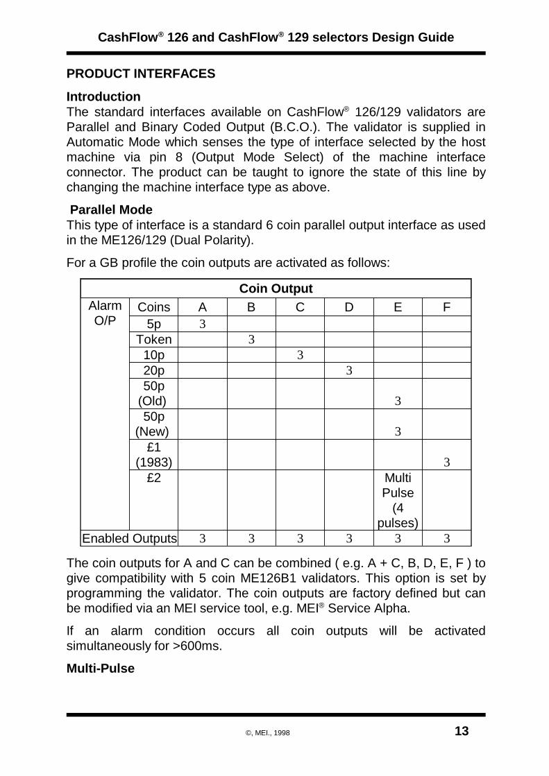
Parallel ModeThis type of interface is a standard 6 coin parallel output interface as usedin the ME126/129 (Dual Polarity).
For a GB profile the coin outputs are activated as follows:
333333Enabled Outputs
MultiPulse
(4pulses)
£23
£1(1983)
350p
(New)
350p
(Old)
320p310p
3Token35p
FEDCBACoinsAlarmO/P
Coin Output
The coin outputs for A and C can be combined ( e.g. A + C, B, D, E, F ) togive compatibility with 5 coin ME126B1 validators. This option is set byprogramming the validator. The coin outputs are factory defined but canbe modified via an MEI service tool, e.g. MEI® Service Alpha.
If an alarm condition occurs all coin outputs will be activatedsimultaneously for >600ms.
Multi-Pulse
CashFlow® 126 and CashFlow® 129 selectors Design Guide
©, MEI., 1998 13

This will only operate when in parallel mode. This factory set option willpulse the GB 50p coin output (of a GB profile) four times on validation of aGB £2 coin. This option can be disabled using the Service Alpha.
Coin validation Inhibits A, B, C, D, E, FTo inhibit coin acceptance the CashFlow® validator offers six individualinhibit inputs.
These inhibits operate for each mode as detailed in the following text.
Parallel Output mode inhibitsThe channels that activate the associated coin output will be inhibitedwhen the inhibit is held High, (e.g. Inhibit A will inhibit coin output Achannels).
The default settings for the GB profiles are:
£1 F50p old & new £2E
20pD10pC
TokenB5pA
Coins InhibitedInhibit Line
CashFlow® 126 and CashFlow® 129 selectors Design Guide
14 ©, MEI., 1998
Coin Output Common LineThis line allows for operation with positive or negative common systems.The interface self-configures by sensing the output common voltagesupplied by the machine on the coin output common line, (pin 2 for a 15way machine interface connector, or pin 3 for a 17 way connector).
All potentials are relative to the 0 volt return line to the machine. pin 11 fora 15 way connector and pin 12 for a 17 way machine interface connector.Negative common operation is selected when pin 2 output common is 0volts or negative with respect to pin 11.
Positive common is selected when pin 2 is more positive than +7 voltswith respect to pin 11.
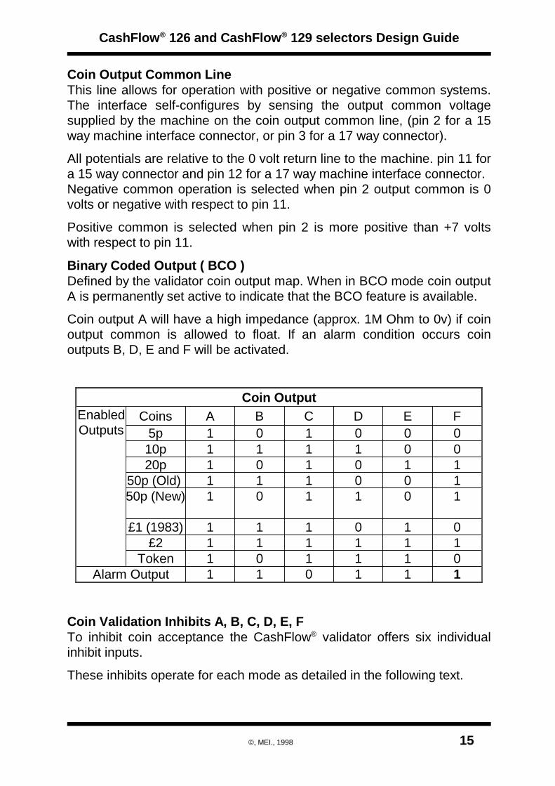
Binary Coded Output ( BCO )Defined by the validator coin output map. When in BCO mode coin outputA is permanently set active to indicate that the BCO feature is available.
Coin output A will have a high impedance (approx. 1M Ohm to 0v) if coinoutput common is allowed to float. If an alarm condition occurs coinoutputs B, D, E and F will be activated.
111011Alarm Output011101Token111111£2010111£1 (1983)
10110150p (New)10011150p (Old) 11010120p00111110p0001015pFEDCBACoinsEnabled
Outputs
Coin Output
Coin Validation Inhibits A, B, C, D, E, FTo inhibit coin acceptance the CashFlow® validator offers six individualinhibit inputs.
These inhibits operate for each mode as detailed in the following text.
CashFlow® 126 and CashFlow® 129 selectors Design Guide
©, MEI., 1998 15

Binary Coded Output Mode InhibitsThe channels inhibited, for a given inhibit line going high are factory set bythe validators coin inhibit map option. When inhibit (A to F) is active, thencoins for the channels specified in the map will be inhibited. The defaultsettings for the GB profile are:
£1F5p, 10p, 50p old & newE
20pDReservedC
TokenB£2A
Coins inhibitedInhibit Line
Automatic Mode - Parallel or BCO SelectionIn this mode the status of the output mode input (on pin 8 of the 17 wayconnector, or pin 7 for the 15 -way connector of the machine interface)selects either the parallel or the binary coded output interface standards.
A logic high signal to this pin will select parallel mode, setting pin 8 to alogic low will select BCO mode. If there is no connection made to pin 8 theinterface will default to parallel mode.
CashFlow® 126 and CashFlow® 129 selectors Design Guide
16 ©, MEI., 1998

ELECTRICAL INTERFACES
IntroductionThis section gives the pin assignments for all connector interfaces usedon the CashFlow® validators and it also includes timing diagrams of thesignals appearing on the input and output lines.
Connector 1, Machine Interface.The interface to the validator from the machine is exactly the same asthose which apply to the MS/ME series validators, with the exception ofpin 8 of the 17-way connector.
Connector 1 can accept either 15 pin or 17 pin interface connectors.
Inhibit 617IA Coin Inhibit-17Inhibit 516IB Coin Inhibit1516Inhibit 115IF Coin Inhibit1415Inhibit 214IE Coin Inhibit1314Inhibit 313ID Coin Inhibit12130V Supply12I0V Supply1112+12V Supply11I+12V Supply1011Inhibit 410IC Coin Inhibit910Accept Output 49OC Coin Output89Select Line8IOutput Mode Select78Accept Output 37OD Coin Output67Accept Output 26OE Coin Output56Polarising Key5-Polarising Key 145Accept Output 14OF Coin Output34
Accept OutputCommon
3ICoin OutputCommon
23Accept Output 52OB Coin Output12Ident signal1OA Coin Output-1
(BACTAStandard) FunctionDefinition
PIN No.
Input or
Output
Functions(Dual Polarity)
15 Way
Connector
17 Way
Connector
Connector types used:- 15 Way Molex SIL 6471 or 17 Way Molex SIL6471.
CashFlow® 126 and CashFlow® 129 selectors Design Guide
©, MEI., 1998 17

Separator Connector (2)This connector is used for connection to the CashFlow® 126 4 way orCashFlow® 129 8 way separators only.
+ 12V 2019+ 12V+ 5V1817 V Reference
Ground1615UnusedGround1413ResetGround1211BusyGround109DataUnused87Unused
Solenoid 265Unused+12V43Unused
Solenoid 121Solenoid 3FunctionPin No.Pin No.Function
Connector type used:- 20 way Molex DIL 901-42-0020.
WARNING:Do not connect ME129, ME126 Active or ME126 Security separators tothis product or damage may result.
CashFlow® 126 and CashFlow® 129 selectors Design Guide
18 ©, MEI., 1998

Routing Plug Connector (3) A 22 way connector located on the front of the validator. It is used toaccept a plug containing wire links or diodes that define the routing andexit path of validated coins. The routing plug is similar to that of theME126 Active and ME129 products, but with 2 extra pins addedtoaccommodate coin routing for outputs G & H.NOTE: These outputs must not be confused with the outputs on Conn. 1.
Connector type used: Molex 22 - way DIL 90142.
NOTE: Neither the 14 nor the 18 pin routing plugs used with the MS/MEseries products are compatible with the CashFlow® 126/129 products.However, it is possible for customers to source an adaptor loom, to MEIdrawing no. 709856001. For detail please contact MEI Technical Support.
Coin Output H2221Coin Output GCoin Output F2019Coin Output ECoin Output D1817Coin Output CCoin Output B1615Coin Output A
Route 1 (d)1413Route 1 (d)Route 2 (c)1211Route 2 (c)Route 3 (a)109Route 3 (a)Route 4 (b)87Route 4 (b)Route 5 (C)65Route 5 (C)Route 6 (D)43Route 6 (D)Route 7 (B)21Route 7 (B)FunctionPin No.Pin No.Function
There are 7 exits (pins 1 to 14) labelled route 1 to 7, and 8 coin outputs(pins 15 to 22) labelled coin output A to H.
GB Coinset Detail
CashFlow® 126 and CashFlow® 129 selectors Design Guide
©, MEI., 1998 19
2PH50p newG
1PF50P oldE
20PD10PC
TOKENB5PA
COIN/TOKEN VALUECOIN OUTPUT

CashFlow® 126/129 separators provide control over the exit path taken bya validated coin. This is referred to as routing and is accomplished byinserting wire links into a 22 way routing plug which is inserted intoconnector 3 of the validator.
NOTE: Fitting a routing plug to the validator will overide all factory routingsettings as long as more than one link is fitted between a coin output anddata pin on this connector.
Routing Plug SignalsThe eight coin output signal lines, A, B, C, D, E, F, G and H correspond toup to fourteen possible coin types. The mapping of coin channels ischannel set dependent. These lines signal the arrival of valid coins.
Links between the coin output signal inputs and the coin route linesspecify the exit paths to be taken by the coins.
CashFlow® 126 and CashFlow® 129 selectors Design Guide
20 ©, MEI., 1998
LowestRoute 712Route 7Exit B12Exit BRoute 634Route 6Exit D34Exit DRoute 556Route 5Exit C56Exit CRoute 478Route 4(Exit ‘b’)78(Exit ‘b’)Route 3910Route 3(Exit ‘a’)910(Exit ‘a’)Route 21112Route 2(Exit ‘c’)1112(Exit ‘c’)
HighestRoute 11314Route 1(Exit ‘d’)1314(Exit ‘d’)Coin A1516Coin BCoin A1516Coin BCoin C1718Coin DCoin C1718Coin DCoin E1920Coin FCoin E1920Coin FCoin G2122Coin HCoin G2122Coin H
FunctionPinNo.
PinNo.
Function
FunctionPinNo.
PinNo.
Function
Coin Exit RoutePriority Order
129 ROUTING PLUG
PINOUTS ANDFUNCTIONS
126 ROUTING PLUG
PINOUTS ANDFUNCTIONS

Route Input Lines - Routes 1-7The CF129 exit routes are marked as Route (1, 2, 3, 4, 5, 6 & 7) with (8)being the default exit route, as standard.Routes 1-7 on CF129 refer to the coin routes 1 to 7, with 1 having highpriority and 7 low priority.Routes 1-7 on CF126 refer to the 4 coin route outputs A, B, C and D asshown in the following table.Note: (d) is the same route as D but has a higher priority.
The CF129 exit routes are marked as Route (1, 2, 3, 4, 5, 6 & 7) with (8)being the default exit route.
A8000B7100D6010C5110(b)4101(a)3001(c)2111(d)1011
126 Route129 RouteSolenoid 1Solenoid 2Solenoid 3
CashFlow® 126 and CashFlow® 129 selectors Design Guide
©, MEI., 1998 21

ROUTING CONFIGURATIONThe CF126 exits routes are marked as (B, C & D) with (A) being thedefault exit route.
ROUTING CONFIGURATION EXAMPLESWhen a routing plug is connected the routes will be set up as designatedby the plug links and routing plug outputs.Where two or more exit routes are specified for a given coin, the highestpriority will be chosen by the validator unless that exit route is beinginhibited by a low voltage signal on its positionwithin the dynamic route inhibit connector.
Here are listed the three most commonly usedrouting plug configurations.1. Single coin to one Exit.2. Single coin to two Exits.3. Two coins to the same Exit.
Example 1:-This shows a single coin to one exit. In thisexample coin E goes to exit C by linking pin 19 to pin 11 using a wire link.
All other coins go to default route.
CashFlow® 126 and CashFlow® 129 selectors Design Guide
22 ©, MEI., 1998
129 Separator 126 SeparatorEnd View
Sol 1
Sol 2
Sol 3
EXITS 1 2 3 4 8 7 6 5 DEXITS A B C
56784321
12
34
5678
Reject
TOP VIEW
D
A B
C
(d) (a) (b) (c)
(d)
(a) (b)
(c)
Routing Plug Viewed From Wire Links End
Example 1
21
19
17
15
13
11
9
7
5
3
Coin A
Coin C
Coin E
Coin G
P i n
1Route 7 (B)
Route 6 (D)
Route 5 (C)
Route 1 (d)
Route 2 (c)
Route 3 (a)
Route 4 (b)
P i n
22
20
18
16
14
12
10
8
6
4
2
Coin B
Coin D
Coin F
Coin H
Route 7 (B)
Route 6 (D)
Route 5 (C)
Route 1 (d)
Route 2 (c)
Route 3 (a)
Route 4 (b)
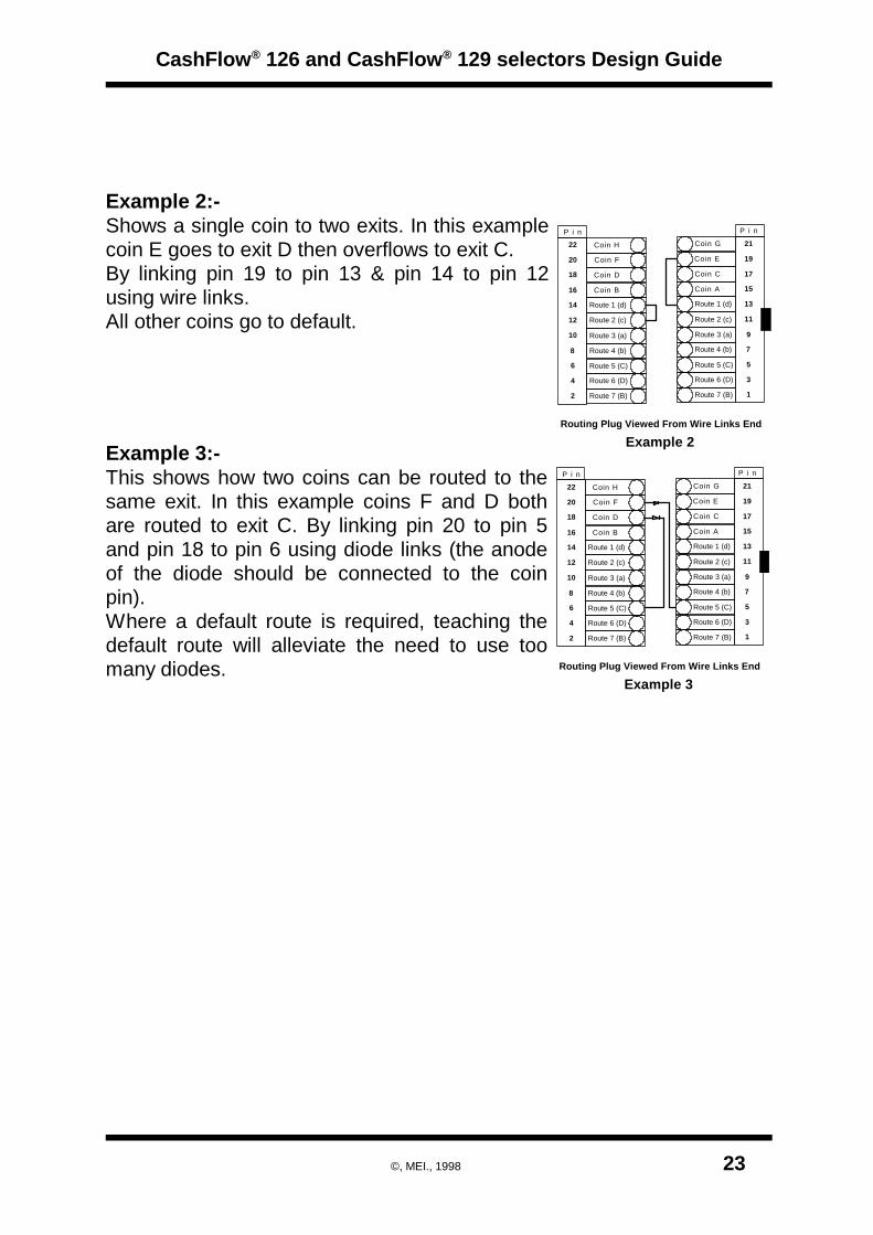
Example 2:-Shows a single coin to two exits. In this examplecoin E goes to exit D then overflows to exit C.By linking pin 19 to pin 13 & pin 14 to pin 12using wire links.All other coins go to default.
Example 3:-This shows how two coins can be routed to thesame exit. In this example coins F and D bothare routed to exit C. By linking pin 20 to pin 5and pin 18 to pin 6 using diode links (the anodeof the diode should be connected to the coinpin).Where a default route is required, teaching thedefault route will alleviate the need to use toomany diodes.
CashFlow® 126 and CashFlow® 129 selectors Design Guide
©, MEI., 1998 23
Routing Plug Viewed From Wire Links End
Example 2
21
19
17
15
13
11
9
7
5
3
Coin A
Coin C
Coin E
Coin G
P i n
1Route 7 (B)
Route 6 (D)
Route 5 (C)
Route 1 (d)
Route 2 (c)
Route 3 (a)
Route 4 (b)
P i n
22
20
18
16
14
12
10
8
6
4
2
Coin B
Coin D
Coin F
Coin H
Route 7 (B)
Route 6 (D)
Route 5 (C)
Route 1 (d)
Route 2 (c)
Route 3 (a)
Route 4 (b)
Routing Plug Viewed From Wire Links End
Example 3
21
19
17
15
13
11
9
7
5
3
Coin A
Coin C
Coin E
Coin G
P i n
1Route 7 (B)
Route 6 (D)
Route 5 (C)
Route 1 (d)
Route 2 (c)
Route 3 (a)
Route 4 (b)
P i n
22
20
18
16
14
12
10
8
6
4
2
Coin B
Coin D
Coin F
Coin H
Route 7 (B)
Route 6 (D)
Route 5 (C)
Route 1 (d)
Route 2 (c)
Route 3 (a)
Route 4 (b)

Connector 4, Dynamic Route Inhibit This direct input from the machine to the front reject cover of the validatoris knows as the Dynamic Route Inhibit. The inhibit placed via thisconnector indicates that a specific route is full. To Inhibit a route this hasto be grounded (i.e. active low to inhibit a route).
Connector type used:- 9 pin SIL - AMP 925366.
GroundGround9
Exit A is theDefault
Route 8 is theDefault
8
LOWESTExit B = Priority 7Divert to Route 77
Exit D = Priority 6Divert to Route 66
Exit C = Priority 5Divert to Route 55
Exit (b) = Priority 4Divert to Route 44
Exit (a) = Priority 3Divert to Route 33
Exit (c )= Priority 2Divert to Route 22
HIGHESTExit (d) = Priority 1Divert to Route 11
Coin ExitPriorities
CF1264 Way Separator
Exits
CF1298 Way Separator
Exit Route
Route InhibitConnector
Pin No.
Coin Exit PrioritiesIf an exit is required to be inhibited, the alternative route/exit must be of alower priority. For example:-If a route inhibit is applied to route 5 ( for the 8 way separator or exit C forthe 4 way separator )then routing can only be diverted to routes 6, 7 or 8the default route on 8 way separators or exits D,B or A for the 4 wayseparator.If route D is required to be diverted to route C on the 126 product thenroute 1 (d) should be used, which can then be diverted to any output.
Connector 5, Serial InterfaceProvision has been made for future access to a comprehensive interfacefacility, but at the present time this connector serves no function.Customers should not connect anything to this connector.
CashFlow® 126 and CashFlow® 129 selectors Design Guide
24 ©, MEI., 1998

Y-chute Interface ConnectorConnections to the Y-chute is made with a Molex type 6471 19-way. Thisconnector is fitted to the dual entry (coin and token) system only. Itprovides an interface for the machine to inhibit acceptance of anycoin/token and also gives a signal to the validator to inhibit coins duringtoken input and to inhibit tokens during coin input.
This interface is not supplied with the single entry system.
12 volts input to theY-chute
Input12 Volts19InputInhibit F18InputInhibit E17InputInhibit D16InputInhibit C15 Inhibit signal from
the machine
InputInhibit B14--Not Used13--Polarisation12
0 volts commoninput to Y-chute
Input0 Volts11
0 volts common tothe validator
Output0 Volts10--Not Used9--Not Used8
Inhibit signals to thevalidator
OutputInhibit B7--Polarisation6
OutputInhibit C5OutputInhibit D4OutputInhibit E3 Inhibit signals to the
validator
OutputInhibit F2
12 volts supply tothe validator
Output12 Volts1
NotesInput / OutputFunctionPinNo.
In dual entry systems the Y-chute forms the interface between thevalidator, Y-chute and the machine. The latter uses the Y-chute interfaceand the validator interface as its main connection points. The coin outputsare signalled from the validator interface. The coin inhibits are connected
CashFlow® 126 and CashFlow® 129 selectors Design Guide
©, MEI., 1998 25

to the Y-chute interface, and the inhibit signals are fed back to thevalidator interface by the host machine interface wiring, as shown below.
With single entry systems the interface is between the validator and themachine only, with no electronics fitted to the Y-chute.
NOTE: When an old, (pre-March 1997), Y chute is used with a BACTA standardmachine interface (BCO) the mode of operation of the Y chute needs tobe changed. (Consult with MEI technical support for further details).
CashFlow® 126 and CashFlow® 129 selectors Design Guide
26 ©, MEI., 1998
ValidatorInterface
Y - ChuteInterface Machine
Coin InhibitsY-Chute Inhibits
Coin Outputs
Dual Entry System ( Coin and Token )
and power and power
Single Entry System ( Coin Only )
ValidatorInterface Machine
Coin Inhibits and power
Coin Outputs

ELECTRICAL SPECIFICATION
Voltage Range 12V (+ 3V maximum, -2V minimum)Current Consumption; Quiesent (Idle) - 35mA
Coin Flight - 65 mAAccept Gate only - 800 mA2 Routing Solenoids - 2,300 mA for 320mS3 Routing Solenoids - 3000 mA for 320 mS
Coin Output Electrical Specification
Output Circuit Block Diagram
Vcc
4k7
1K 56R10n
Logical Outputs
ABCDEF
o/p A
Polarity Sense
o/p Bo/p Co/p Do/p Eo/p F
o/p common
o/po
6X
XOR
i/p
Output Driver Block
Absolute Maximum RatingsOutput Current (O/PA) - F) ± 30 mAMaximum Voltage (O/PA) - F) ± 32 V w.r.t. 0V
CashFlow® 126 and CashFlow® 129 selectors Design Guide
©, MEI., 1998 27
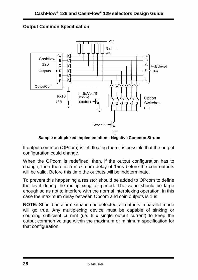
Output Common Specification
Sample multiplexed implementation - Negative Common Strobe
Cashflow126
Outputs
ABCDEF
OutputCom
Strobe 1
Strobe 2
ABCDEF
ABCDEF
MultiplexedBus
Vcc
Option Switchesetc.
R ohms
I= 6xVcc/RRx10
(470)
(4k7)(150mA)
If output common (OPcom) is left floating then it is possible that the outputconfiguration could change.
When the OPcom is redefined, then, if the output configuration has tochange, then there is a maximum delay of 15us before the coin outputswill be valid. Before this time the outputs will be indeterminate.
To prevent this happening a resistor should be added to OPcom to definethe level during the multiplexing off period. The value should be largeenough so as not to interfere with the normal interplexing operation. In thiscase the maximum delay between Opcom and coin outputs is 1us.
NOTE: Should an alarm situation be detected, all outputs in parallel modewill go true. Any multiplexing device must be capable of sinking orsourcing sufficient current (i.e. 6 x single output current) to keep theoutput common voltage within the maximum or minimum specification forthat configuration.
CashFlow® 126 and CashFlow® 129 selectors Design Guide
28 ©, MEI., 1998

Negative Common Voltage RangeThis interface is selected when pin 3 is <2.5V with respect to pin 12. (0V)
Negative Common Outputs:On: Maximum current = 30mA
O/P saturation voltage (Coin O/P - Opcom) <1.5V
Off: 10 uA maximum at 27 volts (Coin O/P - OPcom)
Pulse Width: Switched on for between 80 and 120 ms on acceptance of the appropriate coin.
Negative Output Common Timing Circuit
CashFlow® 126 and CashFlow® 129 selectors Design Guide
©, MEI., 1998 29
OutputCommon
Output
T(o/p valid) = 15 micro seconds
OtherOutputs
to be Set
o/p off
o/p on
100 ms 10%+

Positive Common Voltage Range
Positive Common Operation (O/P Common)This interface is selected when pin 3 is greater than +4.5 volts withrespect to pin 12. (0V)
Output Common Voltage:+7 volts to +26 volts with respect to pin 12.
Positive Common Outputs:On: Maximum current = 40mA
Saturation voltage (Opcom - Coin O/P) <1.5V
Off: 10uA maximum at +27 volts (Opcom - Coin O/P)
Pulse Width: Switched on for between 80 and 120ms on acceptance of appropriate coin.
CashFlow® 126 and CashFlow® 129 selectors Design Guide
30 ©, MEI., 1998
OutputCommon
Output A
T (o/p valid)
BCO Output Indication from "Power ON"
Vsupply
OutputMode Select
100ms max
Coin O/P valid

Binary Coded Output (BCO)BCO mode is indicated by the A output being permanently active. Thisindicator can take up to 100 milliseconds to be established from powerup.
In order to ensure reliable operation of the machine the state of this outputshould be regularly polled (as the coin validator could be reconfiguredwithout the power being removed).
As there are often long machine interface leads involved in coinmechanism interfaces, it is recommended that the coin outputs should bede-bounced in software to reduce the effect of glitches.
Coin Inhibits
Input voltage to enable channels (logic 0) ) <1.0VInput voltage to inhibit channels (logic 1) >4.0V
Input impedance 12 Kohms to +5v.
CashFlow® 126 and CashFlow® 129 selectors Design Guide
©, MEI., 1998 31

MECHANICAL INTERFACE DRAWINGS
The following drawings are included in this section:
CF126 Front Plate DimensionsDrawing Number 32780 Front plate mounting detail.
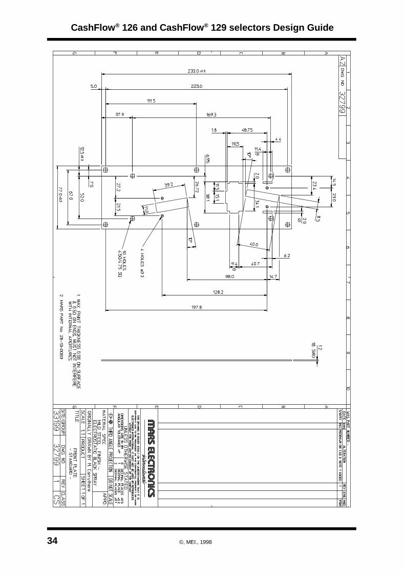
Drawing Number 32799 Standard front plate dimensions.
Drawing Number 35811 Side entry space envelope.
CF126 Top Entry Mounting Space EnvelopeDrawing Number 35812.
CF129 Long Channel Mounting Space EnvelopeDrawing Number 35824 Long channel dimensions.
Drawing Number 35954 CF129 system installation dimensions.(Fitted with Long manifold)
Drawing Number 35961 CF129 system installation dimensions.(Fitted with Short manifold)
CashFlow® 126 and CashFlow® 129 selectors Design Guide
32 ©, MEI., 1998

CashFlow® 126 and CashFlow® 129 selectors Design Guide
©, MEI., 1998 33
CashFlow® 126 and CashFlow® 129 selectors Design Guide
34 ©, MEI., 1998

CashFlow® 126 and CashFlow® 129 selectors Design Guide
©, MEI., 1998 35

CashFlow® 126 and CashFlow® 129 selectors Design Guide
36 ©, MEI., 1998

CashFlow® 126 and CashFlow® 129 selectors Design Guide
©, MEI., 1998 37

CashFlow® 126 and CashFlow® 129 selectors Design Guide
38 ©, MEI., 1998

CashFlow® 126 and CashFlow® 129 selectors Design Guide
©, MEI., 1998 39
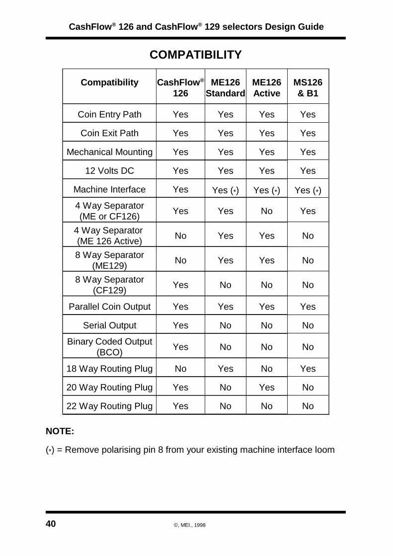
COMPATIBILITY
NoNoNoYes22 Way Routing Plug
NoYesNoYes20 Way Routing Plug
YesNoYesNo18 Way Routing Plug
NoNoNoYesBinary Coded Output(BCO)
NoNoNoYesSerial Output
YesYesYesYesParallel Coin Output
NoNoNoYes8 Way Separator(CF129)
NoYesYesNo8 Way Separator(ME129)
NoYesYesNo4 Way Separator (ME 126 Active)
YesNoYesYes4 Way Separator(ME or CF126)
Yes (*)Yes (*)Yes (*)YesMachine Interface
YesYesYesYes12 Volts DC
YesYesYesYesMechanical Mounting
YesYesYesYesCoin Exit Path
YesYesYesYesCoin Entry Path
MS126& B1
ME126Active
ME126Standard
CashFlow®
126Compatibility
NOTE:
(*) = Remove polarising pin 8 from your existing machine interface loom
CashFlow® 126 and CashFlow® 129 selectors Design Guide
40 ©, MEI., 1998

PERFORMANCE STANDARDS
POWER SUPPLY
Operating Voltage: +12V tolerance = (+ 3V) (- 2V)Supply Voltage Ripple Within Vmin to Vmax up to 100Hz250mV pk - pk for F>100HzCurrent consumption:Quiescent current: 35mA MaxMax current: 2.5A Max (4 solenoids active)
COMPLIANCE CLASSIFICATIONSThe product is designed to the following standards for sale into Europeanmarkets and will carry the “CE” mark.
Electromagnetic Conformance (EMC)The product is designed to comply with the following European standards:EN50082-1 1992 Electromagnetic Compatibility Generic ImmunityStandardEN55022 1995 Limits and methods of measurement of radio disturbancecharacteristics of information technology equipment.
SafetyThe product is intended for use in machines which are designed tocomply with;a) EN60335-1, 3rd Edition, Safety of household and similar electricalappliances, Part 1, General Requirements.”b) BS3456, Safety of household and similar electrical appliances, Part 1,General Requirements.c) BS EN60950 1992, Safety of Information Technology Equipment,including electrical business equipment.
The product is suitable for use in a class 2 (non-earthed or non-grounded)appliance as defined in EN60335.All electrical connections to the acceptor must be rated according to therequirements for “Accessible SELV” circuits as defined in EN60335.
When used in applications where compliance to BS EN60950:1992 isnecessary, the host machine power supply must additionally meet therequirements for SELV limited power supplies as defined in BS EN60950.For these applications, the coin mechanism should be installed so that itis external to any fire enclosure.
CashFlow® 126 and CashFlow® 129 selectors Design Guide
©, MEI., 1998 41

FlammabilityAll major plastic parts will be moulded in materials with a flammabilityrating of 94 V-2 / IEC 707 FV2 or better. Some small parts are moulded inmaterials with a flammability rating of 94 HB / IEC 707 FH2.
Power Supply Input ProtectionOvercurrent protection is not included in the product and must beprovided as part of the machine.Recommended fuse rating at the rated supply of 12V is:
3A Slow blow EN60127Other protection methods may be used providing their over currentcharacteristics remain within the overall operating characteristics of theabove fuse.
Mechanical Parts The product will not contain mechanically moving parts, or sharp edges,which can prevent a hazard in normal use.
Coin SizesCashFlow® 126 and CashFlow® 129 will be able to validate and routecoins within the following range:Circular coins, in the range 15mm to 31.5 mm in diameter.Circular coins, in the range 1.1mm to 3.2mm in thickness.Faceted coins within the relevant coinsets will also be handled.Damaged, bent or very distorted coins may not be validated.
Coin Acceptance RateThe acceptor will validate coins at up to 3 coins per second, when linearlyseparated i.e. >330 ms apart. After a coin has been rejected, no furthercoins will be accepted for a period of 0.5 seconds. Should a further coinbe entered during this period, the reject period will be reinitiated.
Fraud PerformanceDual post gate strobes are fitted to give protection against COAS andStrimmer type frauds. A pre-gate strobe is fitted for protection against“Spoon” fraud.Provision has been made on the PCB for a COAS detector. If the input isseen to go active, the alarm will be sounded.
Where machines do not recognise an all outputs ON as an alarmindication the alarm should be disabled by switching option switch 1 toOFF, otherwise false credit may be given in the event of a fraud attack.
CashFlow® 126 and CashFlow® 129 selectors Design Guide
42 ©, MEI., 1998

ENVIRONMENTAL PERFORMANCE
Temperature RangeNormal operational range 10°C to 40°CFull operational range 0°C to 60°CStorage range -10°C to 75°CMax. rate of change 10°C/hr, non condensing
Humidity RangeOperational10%RH - 90%RH, non condensingStorage 5%RH to 95%RH, non condensing
Temperature / Humidity specification
Temperature oCN = Normal operating rangeF = Full operating rangeS = Storage range
Thermal shockSudden changes of temperature may cause temporary degradation ofperformance. For continuous operation and specified performance withinthe full operational temperature range, the rate of change of temperatureshould not be greater than 10°C per hour, non condensingVibration (through machine mounting)Vibration 0.25g at 5Hz to 500Hz - pseudo random, flat bandwidthCoin validation will not be affected.
CashFlow® 126 and CashFlow® 129 selectors Design Guide
©, MEI., 1998 43
- 10,95100
75
50
25
-20 0 20 40 60 80
- 10, 10
Relative Humidity%35, 95
35, 90
S F N
F S
60, 10 75, 10

TRANSPORTATIONThe following apply to fully packaged units:Shock Half sine, 30g shock, 18ms dur
BS 2011 Part 2.1 EA : 1977Bump 1000 bumps 6ms duration at 25g
BS 2011 Part 2.1 b : 1977Drop - Free Fall 2 drops from 1m onto each face
BS 2011 Part 2.1 ED : 1977Drop and Topple 50mm drop onto each corner
BS2011 Part 2.1 EC : 1977
LIQUID
CashFlow® 100 series validators PCB’s are fitted with splash protectionshields to protect against fluid intrusion. However, prolonged exposure toa salt laden atmosphere, or liquids which dry onto the surface of the PCBcould cause malfunction.
CashFlow® 126 and CashFlow® 129 selectors Design Guide
44 ©, MEI., 1998

CashFlow® 126 and CashFlow® 129 selectors Design Guide
©, MEI., 1998
MEI MAIN AND REGIONAL OFFICES
WWW.MEIGROUP.COM

4
4-Way DIL Switches, 124 Way DIL Teach Switch, 114 way Separation, 8, 23
8
8-Way Separation, 218 way Separation, 8, 23
A
Accept Gate, 9Automatic Mode, 10, 13
B
Binary Coded Output, 10, 13, 15,30Binary Coded Output Mode Inhibits,16Build Options, 6
C
Coin Acceptance Rate, 43Coin Inhibits, 14, 15, 30Coin Output, 26Coin Output Common Line, 14Coin Output Signals, 20Coin Routing, 22Coin Set, 8Coin Sizes, 43Coin Validation, 8Coinset Label, 3Communications Signals, 9Compatibility, 39Conformance to InternationalStandards, 1
D
Dangerous Environments, 1
Diagnostic LED, 11Disposal of Product, 1Dual Entry System, 25Dual Entry Systems, 24Dynamic Route Inhibit, 10, 23
E
Electrical Interfaces, 17Electro-mechanical Conformance,40Electromagnetic Conformance, 41Environmental Performance, 44
F
Factory Programming, 8Flammability, 41Flash Code Sequence, 11Fraud Performance, 43Front Plates, 4
H
Humidity Range, 44
I
Inhibit Signals, 25Inhibited Coins, 9
L
Liquid Protection, 45
M
Machine Interface, 9, 17MEI® Service Alpha, 13Maximum Operating Voltage, 1Maximum Voltage Ratings, 26Mechanical Interface Drawings, 31MEI Offices, 51Multi-Pulse, 9, 14
CashFlow® 126 and CashFlow® 129 selectors Design Guide
INDEX
©, MEI., 1998

N
Negative Common Outputs, 28Negative Common Voltage Range,28
O
Operators Handbook, 8, 12Output Common, 27Output Common Voltage, 29
P
Parallel Mode, 10, 13, 16, 27Parallel Output Mode, 13Parallel Output mode inhibits, 14Parallel Output Mode., 9Performance Standards, 40Positive Common Outputs, 29Positive Common Voltage Range,29Post-Gate Strobes, 11Power Supply, 41Power Supply Input Protection, 43Pre-Gate Strobe, 11Product Features, 7Product Identification, 3Product Interfaces, 13Product Operation, Electrical, 10Product Range, 2
R
Reject Covers, 3, 5Reject Route, 9Rejected Coins, 9Rotary Data Switch, 11, 12Route Input Lines, 21Routing Plug, 10, 19, 20, 21, 22Routing Plug Connector, 19
S
Safety, 1, 41Separator Connection, 10Separator Connector, 18Single Entry System, 24, 25
T
Temperature Range, 44Transportation, 45
V
Validator, 9Validator Connector, 10Validator Connectors, 10, 17, 18,19, 23Validator Reject Flap, 9
Y
Y-chute, 24, 25Y-chute Interface Connector, 24
CashFlow® 126 and CashFlow® 129 selectors Design Guide
INDEX
©, MEI., 1998

CashFlow® 126 and CashFlow® 129 selectors Design Guide
©, MEI., 1998

CashFlow® 126 and CashFlow® 129 selectors Design Guide
©, MEI., 1998

Representative