
CASE STUDY YOUNGS CREEK - Washington, USA creek case study… · · 2016-02-29In October 2011,...
2
In October 2011, the Snohomish County Public Utility District opened the first new hydroelectric project in Washington State in nearly 20 years. The $29 million project located south of Sultan generates enough power, on average, for about 2,000 homes. The Youngs Creek Project gives the PUD greater flexibility with its power supply as it’s a locally generated, reliable resource that provides energy at times of the year when it’s needed the most. Gilkes supplied a complete water to wire solution for the project. The turbine was designed in the UK and completely manufactured, assembled and tested in North America. The Pelton runner was manufactured from fully CNC machined forging and all anciliary equipment as far as possible was designed and sourced in the USA. CASE STUDY YOUNGS CREEK - Washington, USA Customer: PUD NO. 1 Snohomish County, Washington Location: Southeast of the City of Monroe, Washington USA Head: 268m Flow: 3.396 m 3 /s Turbine type: 1850 Horizontal Twin Jet Pelton Speed: 360rpm Turbine power output: 7983kW Generator output power: 7775kW KEY STATISTICS CONTACT Email: [email protected] Tel: 01539 720028 Fax: 01539 732110 www.gilkes.com Gilbert Gilkes & Gordon Ltd, Canal Head North, Kendal, Cumbria LA9 7BZ. Registration No.173768 London 1. Turbine shaft manufacture 2. Machined Pelton runner 3. Runner installed 4. Turbine Installation
Transcript of CASE STUDY YOUNGS CREEK - Washington, USA creek case study… · · 2016-02-29In October 2011,...
In October 2011, the Snohomish County Public Utility District opened the first new hydroelectric project in Washington State in nearly 20 years. The $29 million project located south of Sultan generates enough power, on average, for about 2,000 homes.
The Youngs Creek Project gives the PUD greater flexibility with its power supply as it’s a locally generated, reliable resource that provides energy at times of the year when it’s needed the most.
Gilkes supplied a complete water to wire solution for the project. The turbine was designed in the UK and completely manufactured, assembled and tested in North America. The Pelton runner was manufactured from fully CNC machined forging and all anciliary equipment as far as possible was designed and sourced in the USA.
CASE STUDYYOUNGS CREEK - Washington, USA
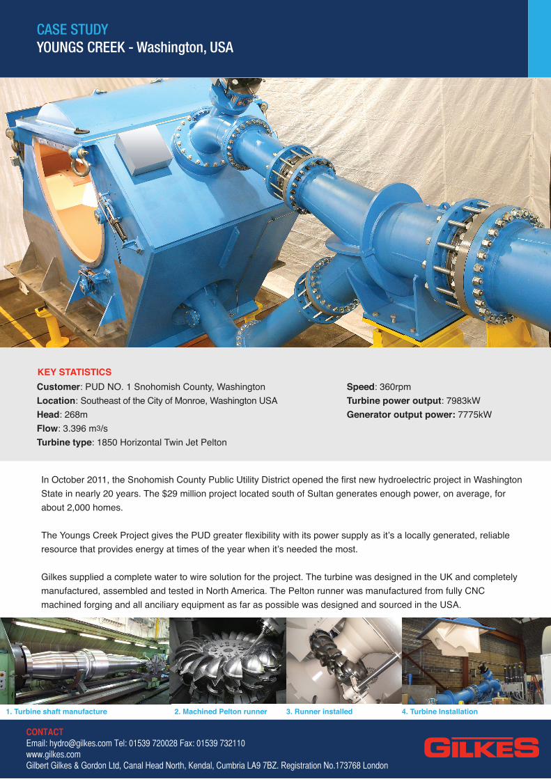
Customer: PUD NO. 1 Snohomish County, WashingtonLocation: Southeast of the City of Monroe, Washington USAHead: 268mFlow: 3.396 m3/sTurbine type: 1850 Horizontal Twin Jet Pelton
Speed: 360rpmTurbine power output: 7983kWGenerator output power: 7775kW
KEY STATISTICS
CONTACTEmail: [email protected] Tel: 01539 720028 Fax: 01539 732110www.gilkes.comGilbert Gilkes & Gordon Ltd, Canal Head North, Kendal, Cumbria LA9 7BZ. Registration No.173768 London
1. Turbine shaft manufacture 2. Machined Pelton runner 3. Runner installed 4. Turbine Installation

CASE STUDYYOUNGS CREEK - Washinton USA
CONTACTEmail: [email protected]: 01539 720028Fax: 01539 732110www.gilkes.comGilbert Gilkes & Gordon Ltd, Canal Head North, Kendal, Cumbria LA9 7BZ. Registration No.173768 London
Gilkes scope of supply• Inlet piping to connect to penstock • Turbine inlet valve and bypass system • One horizontal-shaft twin jet Pelton turbine and inlet piping • Hydraulic Pressure Unit • One 6.9KV synchronous generator with brakes. • Air-blast bearing oil cooling system • Brushless excitation system, voltage regulator and associated
equipment, including instrument transformers. • Generator switchgear assembly • Neutral grounding equipment. Surge capacitors and lightning
arrestors • Generator breaker and instrument transformers• Generator step-up transformer, circuit switcher and disconnect
switches• Station service equipment, including transformer, circuit
breaker, AC and DC panel boards, DC station battery system, and inverter
• Auxiliary equipment and station services motor control centre • Two propane back-up generators with instruments and controls • Generator and turbine control system, including protective
relays, RTU for utility communication, meters, instruments, synchronizing equipment, programmable logic controller (PLC), a panel mounted Human Machine Interface (HMI), and desktop SCADA PC based operator’s terminal and monitor
• Intake control panel including PLC and communications equipment for monitoring and remote control of the intake
• RTU and communications equipment• Shop set-up and assembly of mechanical components prior to
shipping• Factory acceptance testing of turbine, generator, step-up transformer
and control panel prior to shipment• All other related equipment to provide a complete “water to
wire” generating system• Integration and coordination of all equipment and controls to
provide a complete system• All required anchor bolts and foundation plates for mounting of
turbine, valves, generator, and ancillary equipment• Delivery and offloading at the project site • On site supervision of installation of all above equipment • Commissioning and start-up services including field-testing• Operation and troubleshooting of the completed project during
a 10-day test period• Performance testing of the installed turbine/generator
The design of the equipment listed in the scope of supplyincluded the following activities• Determination of all equipment weights, loads and stresses due
to both normal and possible abnormal operating conditions• Design and preparation of shop drawings detailing all interconnecting
electrical wiring between equipment components supplied • Interconnecting wiring drawings including conductor type and size,
terminal strip and conductor connection details and designations. • Conduit routing drawing and schedule showing all required
conduits, their size, starting and ending points, and number and size of conductors required in each conduit.
• A complete instrument list with function, control wiring, and set-points. • Detailed logic diagrams illustrating the control logic of plant
start- up, operation and shutdown logic programming of all plant control, PLC, and remote communications systems
• Testing of PLC programming and remote system operation prior to shipment
• Calculation of protective relay settings through performance of a relay coordination study. All protective relays were then be pre-set at the factory before shipment
• All protective relays were double-checked for proper setting and operation in the field prior to plant start-up
• Calculation of unit stability and frequency control stability parameters, including water hammer analysis, water starting time, unit inertia pipeline pressure rise and initial needle jet controller gain (proportional), integral and derivative settings to keep penstock pressure rise under all load rejection and system operating scenarios to 10% or less