Case study of the rockpass system at Kloof No. 3 Shaft · The majority of the problematic...
4
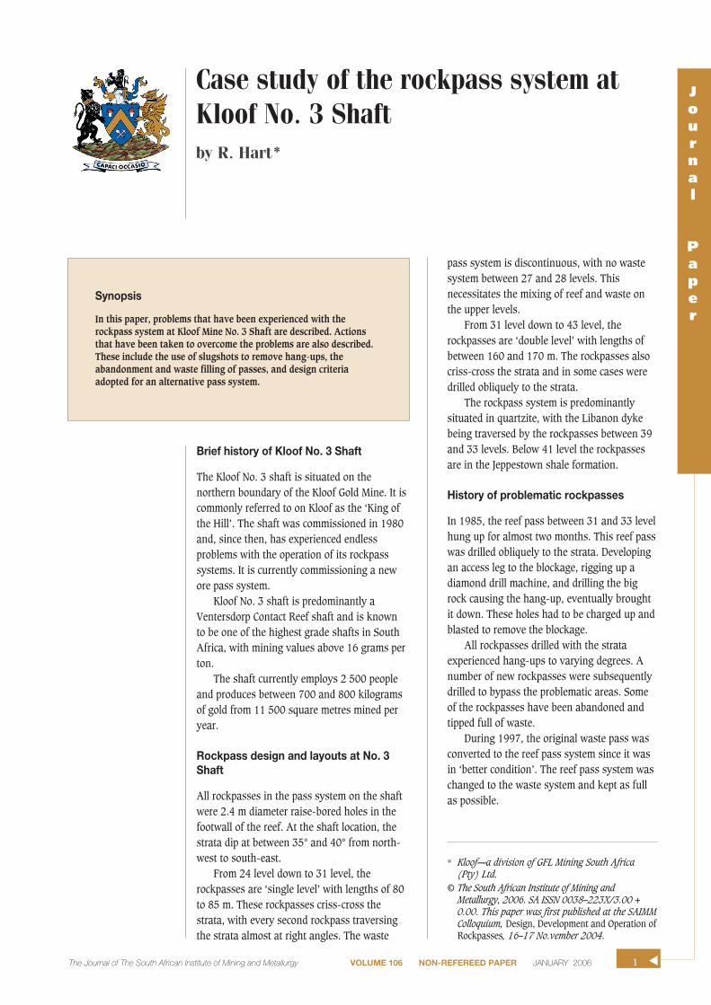
J o u r n a l P a p e r Brief history of Kloof No. 3 Shaft The Kloof No. 3 shaft is situated on the northern boundary of the Kloof Gold Mine. It is commonly referred to on Kloof as the ‘King of the Hill’. The shaft was commissioned in 1980 and, since then, has experienced endless problems with the operation of its rockpass systems. It is currently commissioning a new ore pass system. Kloof No. 3 shaft is predominantly a Ventersdorp Contact Reef shaft and is known to be one of the highest grade shafts in South Africa, with mining values above 16 grams per ton. The shaft currently employs 2 500 people and produces between 700 and 800 kilograms of gold from 11 500 square metres mined per year. Rockpass design and layouts at No. 3 Shaft All rockpasses in the pass system on the shaft were 2.4 m diameter raise-bored holes in the footwall of the reef. At the shaft location, the strata dip at between 35° and 40° from north- west to south-east. From 24 level down to 31 level, the rockpasses are ‘single level’ with lengths of 80 to 85 m. These rockpasses criss-cross the strata, with every second rockpass traversing the strata almost at right angles. The waste pass system is discontinuous, with no waste system between 27 and 28 levels. This necessitates the mixing of reef and waste on the upper levels. From 31 level down to 43 level, the rockpasses are ‘double level’ with lengths of between 160 and 170 m. The rockpasses also criss-cross the strata and in some cases were drilled obliquely to the strata. The rockpass system is predominantly situated in quartzite, with the Libanon dyke being traversed by the rockpasses between 39 and 33 levels. Below 41 level the rockpasses are in the Jeppestown shale formation. History of problematic rockpasses In 1985, the reef pass between 31 and 33 level hung up for almost two months. This reef pass was drilled obliquely to the strata. Developing an access leg to the blockage, rigging up a diamond drill machine, and drilling the big rock causing the hang-up, eventually brought it down. These holes had to be charged up and blasted to remove the blockage. All rockpasses drilled with the strata experienced hang-ups to varying degrees. A number of new rockpasses were subsequently drilled to bypass the problematic areas. Some of the rockpasses have been abandoned and tipped full of waste. During 1997, the original waste pass was converted to the reef pass system since it was in ‘better condition’. The reef pass system was changed to the waste system and kept as full as possible. Case study of the rockpass system at Kloof No. 3 Shaft by R. Hart* Synopsis In this paper, problems that have been experienced with the rockpass system at Kloof Mine No. 3 Shaft are described. Actions that have been taken to overcome the problems are also described. These include the use of slugshots to remove hang-ups, the abandonment and waste filling of passes, and design criteria adopted for an alternative pass system. * Kloof—a division of GFL Mining South Africa (Pty) Ltd. © The South African Institute of Mining and Metallurgy, 2006. SA ISSN 0038–223X/3.00 + 0.00. This paper was first published at the SAIMM Colloquium, Design, Development and Operation of Rockpasses, 16–17 No.vember 2004. 1 The Journal of The South African Institute of Mining and Metallurgy VOLUME 106 NON-REFEREED PAPER JANUARY 2006 ▲
Transcript of Case study of the rockpass system at Kloof No. 3 Shaft · The majority of the problematic...
Journal
Paper
Brief history of Kloof No. 3 Shaft
The Kloof No. 3 shaft is situated on thenorthern boundary of the Kloof Gold Mine. It iscommonly referred to on Kloof as the ‘King ofthe Hill’. The shaft was commissioned in 1980and, since then, has experienced endlessproblems with the operation of its rockpasssystems. It is currently commissioning a newore pass system.
Kloof No. 3 shaft is predominantly aVentersdorp Contact Reef shaft and is knownto be one of the highest grade shafts in SouthAfrica, with mining values above 16 grams perton.
The shaft currently employs 2 500 peopleand produces between 700 and 800 kilogramsof gold from 11 500 square metres mined peryear.
Rockpass design and layouts at No. 3Shaft
All rockpasses in the pass system on the shaftwere 2.4 m diameter raise-bored holes in thefootwall of the reef. At the shaft location, thestrata dip at between 35° and 40° from north-west to south-east.
From 24 level down to 31 level, therockpasses are ‘single level’ with lengths of 80to 85 m. These rockpasses criss-cross thestrata, with every second rockpass traversingthe strata almost at right angles. The waste
pass system is discontinuous, with no wastesystem between 27 and 28 levels. Thisnecessitates the mixing of reef and waste onthe upper levels.
From 31 level down to 43 level, therockpasses are ‘double level’ with lengths ofbetween 160 and 170 m. The rockpasses alsocriss-cross the strata and in some cases weredrilled obliquely to the strata.
The rockpass system is predominantlysituated in quartzite, with the Libanon dykebeing traversed by the rockpasses between 39and 33 levels. Below 41 level the rockpassesare in the Jeppestown shale formation.
History of problematic rockpasses
In 1985, the reef pass between 31 and 33 levelhung up for almost two months. This reef passwas drilled obliquely to the strata. Developingan access leg to the blockage, rigging up adiamond drill machine, and drilling the bigrock causing the hang-up, eventually broughtit down. These holes had to be charged up andblasted to remove the blockage.
All rockpasses drilled with the strataexperienced hang-ups to varying degrees. Anumber of new rockpasses were subsequentlydrilled to bypass the problematic areas. Someof the rockpasses have been abandoned andtipped full of waste.
During 1997, the original waste pass wasconverted to the reef pass system since it wasin ‘better condition’. The reef pass system waschanged to the waste system and kept as fullas possible.
Case study of the rockpass system atKloof No. 3 Shaftby R. Hart*
Synopsis
In this paper, problems that have been experienced with therockpass system at Kloof Mine No. 3 Shaft are described. Actionsthat have been taken to overcome the problems are also described.These include the use of slugshots to remove hang-ups, theabandonment and waste filling of passes, and design criteriaadopted for an alternative pass system.
* Kloof—a division of GFL Mining South Africa(Pty) Ltd.
© The South African Institute of Mining andMetallurgy, 2006. SA ISSN 0038–223X/3.00 +0.00. This paper was first published at the SAIMMColloquium, Design, Development and Operation ofRockpasses, 16–17 No.vember 2004.
1The Journal of The South African Institute of Mining and Metallurgy VOLUME 106 NON-REFEREED PAPER JANUARY 2006 ▲

Case study of the rockpass system at Kloof No. 3 Shaft
By trial and error, a minimum distance from the top of thepass was determined for all reef passes and the reef was notpulled down below this level. These distances vary from 30 m in some cases to over 100 m in others. As a result ofthis, the current lock up of ore at No. 3 shaft is estimated tobe between 20 000 and 40 000 tons.
Failure modes of the orepasses
Depth below surface obviously plays a role and is quiteevident at No. 3 shaft. The ‘shallower’ rockpasses down to adepth of 2 500 m show few signs of scaling and noproblematic blockages.
Scaling along strike or ‘dog earing’ is predominantly thefailure mode of the deeper section rockpasses. As shown inFigures 2 and 3, this scaling occurs at 90º to the direction ofaction of the major principal stress—in the case of theWitwatersrand formation, the scaling direction is along strike.
The longer the rockpass, the more scaling encountered.Minimal problems are experienced with the rockpass lengthless than 80 m, while all the longer rockpasses areproblematic. There is greater impact and wear in longerpasses. The estimated average cross sectional area of somerockpasses has increased 10-fold from 3.5 m2 to over 35 m2.The volume, and hence cross-sectional area, was determinedby the storage capacity of the rockpass. An incident has beenexperienced where the self-mining of a rockpass migratedinto the haulage on the level below. An example of this isillustrated in Figure 3 in which rockpasses self-mined intothe 39 level tip area. 30 000 tons of waste was required to fillthis pass, and the filling operation took 9 months tocomplete.
Geological features do increase the risk of failure inrockpasses and should be avoided if possible. At No. 3 shaftthe rockpasses traversing the Libanon dyke show verypronounced scaling in the dyke area. Less scaling is evidentbelow the dyke, so any large rock would hang-up at this‘bottleneck’.
Impact wear does occur just below the tip grizzly, but isminimal.
▲
2 JANUARY 2006 VOLUME 106 NON-REFEREED PAPER The Journal of The South African Institute of Mining and Metallurgy
Figure 2—Rockpass dog earing
Figure 1—Rockpass scaling in the strike direction
Figure 3—Self-mining of rockpass into the 39 level tip area
Figure 4—Large rock in a rockpass

The majority of the problematic rockpasses and hang-upsat Kloof No. 3 shaft are as a result of large rocks scaling.Large seismic events in the shaft pillar area are known toaccelerate the scaling. The dislodged slabs drop down to a‘narrower’ portion of the rockpass. These all occur at 20 to40 m from the bottom. These rocks do not immediately blockthe rockpass. The broken rock somehow finds its way pastthese rocks. Some massive ‘buses’ are still identifiable after10 years. However, as more scaling occurs, the rocks start tointerlock and block the flow of rock. Examples of blockagesby large rocks are shown in Figures 4 and 5.
Dealing with disrupted ore flow
All blockages normally occurred at the same place in eachrockpass. Concussion blasting was used to dislodge theblockages. Access ways were developed in some cases to thenormal hang-up position to deal with the hang-up. Any suchaccess ways must be designed to go flat on the last leg. Inone case an access way from 39 level into the rockpass waslaid out in such a manner that the last leg would be levelgrade for 12 m from the centre line of the original raise boredhole. The access way holed into the rockpass even beforeturning level for the last leg. Entry could be gained into therockpass using this access way, and it was possible to movearound on a large rock approximately 22 m long that waslying across the original 2.4 m diameter rockpass. All accessways have subsequently been abandoned due to the self-mining into them of the rockpass.
Diamond drill holes and raisebore pilot holes were alsodrilled in attempts to pull up explosive charges to get them inclose proximity to the blockage. Minimal successes were hadusing this method.
In the late 1980s, slugshots became available. A slugshotcomprises 5 kg of high explosive shooting a copper slug of0.8 kg for a maximum application distance of 60 m. Due to
the high velocity of over 6 000 m/h and the inertia of thecopper slug, key blocks and medium thick rocks can bedislodged or broken and assist in the removal of the hang-up. Slugshots do not work if the key rock is too thick oroffers an oblique face towards the slugshot. In desperatetimes desperate measures are taken, and the record slugshotconsumption in one month was 78, with 13 of them beingblasted simultaneously at a hang-up in one case. Thebulkhead was destroyed with the hang-up remaining!
In 1997, the super slugshot or Blockbuster wasmarketed. It uses 9.5 kg of explosives to fire a 4.0 kg copperslug over a maximum application distance of 120 m. Themajority of hang-ups are now removed using this method of‘slugshotting’ the obstruction. Normally 2 slugshots areblasted simultaneously at the key block.
Figures 6 and 7 illustrate the aiming of a slugshot andthe slugshot mounted and ready to fire.
Case study of the rockpass system at Kloof No. 3 ShaftJournal
Paper
3The Journal of The South African Institute of Mining and Metallurgy VOLUME 106 NON-REFEREED PAPER JANUARY 2006 ▲Figure 6—Aiming of the slugshot
Figure 5—Blockage caused by a large rock in a rockpass
Figure 7—Slugshot ready to fire at a hang-up

Case study of the rockpass system at Kloof No. 3 Shaft
Safe procedure when blasting slugshots
The following points summarize the actions adopted toensure safe removal of hang-ups using slugshots.
➤ Concussion blast the rockpass by pushing up chargesfrom outside in the conventional manner
➤ Allow at least 24 hours for rockpass to settle➤ Ensure no fines are coming down by decking off the
discharge chute➤ Observe that no more than a trickle of water is coming
down the rockpass and the water must run clear. Donot enter if muddy water is coming down
➤ Push up an air hose for ventilation➤ Examine for obvious loose slabs➤ Install ladders to gain access for line of sight to the
blockage➤ Examine the area where the support bar is to be
installed➤ Always ensure that the escape route is unobstructed to
allow for fast evacuation➤ No more than two people to be inside the rockpass at a
time➤ Aim the slugshot at ‘square on’ corners of key blocks➤ Ensure that a good spotlight is available➤ When blasting more than one slugshot at a time, set off
simultaneously by means of electric detonators.
Experiences with support and lining of rockpasses
Although some of the other shafts at Kloof have usedconcrete rings to support rockpasses, this has not been doneat any No. 3 Shaft rockpass. Concrete lining cannot protectthe rockpass at impact zones. Concrete rings do not lastindefinitely and once they have deteriorated to the extent thatthey become detached, removal of the rings from therockpass is a serious problem.
The application of a spray on abrasion-resistant skin,such as shotcrete with andesite lava aggregate, does assist inslowing down the abrasive wear in the rockpass, but does notprevent stress induced fracturing. Within three months ofcommissioning an internal rockpass system that had andesitelava shotcrete applied, big rocks with the layer of shotcretesupport were being removed from the rockpass.
Rock bolting and the use of flexible tendons to support arockpass has been done, but, within six months, theremnants of the 4.5 m tendons were coming out with scaledrocks.
Design criteria for an alternative rockpass system
An alternative reef pass system has been designed for No. 3shaft from 35 level down to 44 level. The new orepass systemhas been designed to traverse the strata almost at rightangles. The Libanon dyke and the shale all cut through theorepass at right angles. This has been shown to minimize therisk of stress-induced scaling.
No support of the ore pass was done due to timeconstraints since the current ore passes are deterioratingrapidly.
The new orepasses will be kept relatively empty in theinitial stages to prevent the broken rock from forming‘arches’. This bridging is more likely to occur in new raisebored rockpasses with smooth walls. Once the stress-inducedfracturing causes the walls to scale and become uneven,bridging is less likely. Once this is evident, the orepass willbe operated as full as practically possible, since it has beenproven that broken rock acts as support for the rockpass andalso reduces the wear due to impact.
Old reef pass system
The old reef pass system will be emptied and filled up withwaste where waste is available.
At the beginning of October 2004, the process of emptingthe first standby reef pass from 33 level to 35 levelcommenced. This 155 m long reef pass of 3.5m2 cross-sectional area originally had a storage capacity of 875 tons.When the emptying started, it contained 105 m of reef and anestimated 3 800 tons, calculated assuming an estimated 22 m2 average cross-sectional area. The ore discharged for 2 hours before it stopped flowing. A concussion bomb wasblasted and it ran for another 40 minutes. This process ofblasting was continued and ore discharged from this ore passfor a total of 185 minutes. It is still not empty as there is noventilation flow through it. The rate of discharge wasestimated at between 30 and 70 tons per minute. Thedischarged ore was estimated to be more than 9 000 tons.
Two marker boxes were dropped into the reef pass beforethe empting started. One was put in on 33 level and one on35 level. At that stage it was estimated that the systemcontained approximately 20 000 tons below 33 level. Threeweeks later neither of these markers had emerged despitehoisting 50 000 tons. It is virtually impossible to judgeaccurately the storage capacity of the rockpasses at Kloof No. 3 Shaft. Only once the new orepass has been commis-sioned and the old one emptied, will the actual sizes of thereef passes be known.
Conclusion
Rockpass systems are vital for the vertical transport of rock tothe shaft bottom. They form an integral and critical part ofthe mining process, yet little attention is given to theplanning, design and operation of the rockpass system. If theplanning and design is done correctly at the initial stages ofthe shaft design, and sufficient capital is invested in therockpass system, then expensive, hazardous and time-consuming rehabilitation work or replacement of the systemcan be avoided. ◆
▲
4 JANUARY 2006 VOLUME 106 NON-REFEREED PAPER The Journal of The South African Institute of Mining and Metallurgy