Case Study in Survivable Network System Analysis
37
TECHNICAL REPORT CMU/SEI-98-TR-014 ESC-TR-98-014 A Case Study in Survivable Network System Analysis R. J. Ellison R. C. Linger T. Longstaff N. R. Mead September 1998
Transcript of Case Study in Survivable Network System Analysis

TECHNICAL REPORTCMU/SEI-98-TR-014
ESC-TR-98-014
A Case Study inSurvivable NetworkSystem AnalysisR. J. EllisonR. C. LingerT. LongstaffN. R. Mead
September 1998


Pittsburgh, PA 15213-3890
A Case Study inSurvivable NetworkSystem Analysis
CMU/SEI-98-TR-014ESC-TR-98-014
R. J. EllisonR. C. LingerT. LongstaffN. R. Mead
September 1998
Networked Systems Survivability Program
USAF Embedded Computer Resources SupportImprovement Program (ESIP)
Unlimited distribution subject to the copyright.

This report was prepared for the
SEI Joint Program OfficeHQ ESC/DIB5 Eglin StreetHanscom AFB, MA 01731-2116
The ideas and findings in this report should not be construed as an official DoD position. It is published in the interest ofscientific and technical information exchange.
FOR THE COMMANDER
(signature on file)
Mario Moya, Maj, USAFSEI Joint Program Office
This work is sponsored by the U.S. Department of Defense.This report and the effort to produce it were sponsored by USAF Embedded Computer Resources SupportImprovement Program (ESIP) and the U.S. Department of Defense.
Copyright 1998 by Carnegie Mellon University.
NO WARRANTY
THIS CARNEGIE MELLON UNIVERSITY AND SOFTWARE ENGINEERING INSTITUTE MATERIAL ISFURNISHED ON AN "AS-IS" BASIS. CARNEGIE MELLON UNIVERSITY MAKES NO WARRANTIES OF ANYKIND, EITHER EXPRESSED OR IMPLIED, AS TO ANY MATTER INCLUDING, BUT NOT LIMITED TO,WARRANTY OF FITNESS FOR PURPOSE OR MERCHANTABILITY, EXCLUSIVITY, OR RESULTS OBTAINEDFROM USE OF THE MATERIAL. CARNEGIE MELLON UNIVERSITY DOES NOT MAKE ANY WARRANTY OFANY KIND WITH RESPECT TO FREEDOM FROM PATENT, TRADEMARK, OR COPYRIGHT INFRINGEMENT.
Use of any trademarks in this report is not intended in any way to infringe on the rights of the trademark holder.
Internal use. Permission to reproduce this document and to prepare derivative works from this document for internal use isgranted, provided the copyright and "No Warranty" statements are included with all reproductions and derivative works.
External use. Requests for permission to reproduce this document or prepare derivative works of this document for externaland commercial use should be addressed to the SEI Licensing Agent.
This work was created in the performance of Federal Government Contract Number F19628-95-C-0003 with CarnegieMellon University for the operation of the Software Engineering Institute, a federally funded research and developmentcenter. The Government of the United States has a royalty-free government-purpose license to use, duplicate, or disclose thework, in whole or in part and in any manner, and to have or permit others to do so, for government purposes pursuant to thecopyright license under the clause at 52.227-7013.
This document is available through Asset Source for Software Engineering Technology (ASSET): 1350 Earl L. Core Road;PO Box 3305; Morgantown, West Virginia 26505 / Phone: (304) 284-9000 or toll-free in the U.S. 1-800-547-8306 / FAX:(304) 284-9001 World Wide Web: http://www.asset.com / e-mail: [email protected]
Copies of this document are available through the National Technical Information Service (NTIS). For information onordering, please contact NTIS directly: National Technical Information Service, U.S. Department of Commerce,Springfield, VA 22161. Phone: (703) 487-4600.
This document is also available through the Defense Technical Information Center (DTIC). DTIC provides access to andtransfer of scientific and technical information for DoD personnel, DoD contractors and potential contractors, and other U.S.Government agency personnel and their contractors. To obtain a copy, please contact DTIC directly: Defense TechnicalInformation Center / Attn: BRR / 8725 John J. Kingman Road / Suite 0944 / Ft. Belvoir, VA 22060-6218 / Phone: (703)767-8274 or toll-free in the U.S.: 1-800 225-3842.

CMU/SEI-98-TR-014 i
Table of Contents
Abstract vii
1 Network System Survivability 11.1 Survivability Concepts 11.2 The Survivable Network Analysis Method 2
2 Sentinel: The Case Study Subsystem 5
3 Applying the Survivable NetworkAnalysis Method to Sentinel 7
3.1 Method Application 7Step 1: System Definition 8Step 2: Essential Capability Definition 10Step 3: Compromisable Capability Definition 10Step 4: Survivability Analysis 12
4 Lessons Learned 19
5 Acknowledgements 21
References 23

ii CMU/SEI-98-TR-014

CMU/SEI-98-TR-014 iii
List of Figures
Figure 1. The Survivable Network AnalysisMethod 2
Figure 2. Survivability Map Template 3Figure 3. Meetings and Working Sessions in
SNA Method Application 7Figure 4. Original Sentinel Architecture 9Figure 5. Sentinel Architecture with Survivability
Modifications 15

iv CMU/SEI-98-TR-014

CMU/SEI-98-TR-014 v
List of Tables
Table 1. Sentinel Subsystem Survivability Map 14

vi CMU/SEI-98-TR-014

CMU/SEI-98-TR-014 vii
Abstract
This paper presents a method for analyzing the survivability of distributed network systemsand an example of its application. Survivability is the capability of a system to fulfill its mis-sion, in a timely manner, in the presence of attacks, failures, or accidents. Survivability re-quires capabilities for intrusion resistance, recognition, and recovery. The Survivable Net-work Analysis (SNA) method builds on the Information Security Evaluation previouslydeveloped by permitting assessment of survivability strategies at the architecture level. Stepsin the SNA method include system mission and architecture definition, essential capabilitydefinition, compromisable capability definition, and survivability analysis of architecturalsoftspots that are both essential and compromisable. Intrusion scenarios play a key role in themethod. SNA results are summarized in a Survivability Map which links recommended sur-vivability strategies for resistance, recognition, and recovery to the system architecture andrequirements. This case study summarizes the application and results of applying the SNAmethod to a subsystem of a large-scale, distributed healthcare system. The study recom-mended specific modifications to the subsystem architecture to support survivability objec-tives. Positive client response to study recommendations suggests that the method can pro-vide significant added value for ensuring survivability of system operations. As a result ofthis case study, the SNA method, artifacts, and lessons learned will be available to apply ar-chitectural analysis for survivability to proposed and legacy DoD distributed systems.

viii CMU/SEI-98-TR-014

CMU/SEI-98-TR-014 1
1 Network System Survivability
1.1 Survivability ConceptsAs part of its Survivable Systems Initiative, the CERT® Coordination Center (CERT/CC) ofthe Software Engineering Institute (SEI) at Carnegie Mellon University is developing tech-nologies and methods for analyzing and designing survivable network systems [Ellison 97,Linger 98, Lipson 97]. Survivability is defined as the capability of a system to fulfill its mis-sion, in a timely manner, in the presence of attacks, failures, or accidents. Unlike traditionalsecurity measures that require central control and administration, survivability addresseshighly distributed, unbounded network environments with no central control or unified secu-rity policy. Survivability focuses on delivery of essential services and preservation of essen-tial assets, even when systems are penetrated and compromised. As an emerging discipline,survivability builds on existing disciplines, including security [Summers 97], fault tolerance[Mendiratta 92], and reliability [Musa 87], and introduces new concepts and principles.
The focus of survivability is on delivery of essential services and preservation of essentialassets during attack and compromise, and timely recovery of full services and assets follow-ing attack. Essential services and assets are defined as those system capabilities that are criti-cal to fulfilling mission objectives. Survivability depends on three key system capabilities:resistance, recognition, and recovery. Resistance is the capability of a system to repel attacks.Recognition is the capability to detect attacks as they occur, and to evaluate the extent ofdamage and compromise. Recovery, a hallmark of survivability, is the capability to maintainessential services and assets during attack, limit the extent of damage, and restore full serv-ices following attack.
® CERT is registered in the U.S. Patent and Trademark Office.

2 CMU/SEI-98-TR-014
STEP 1:System Definition:• Mission requirements definition• Architecture definition and elicitation
STEP 2:Essential Capability Definition:• Essential service/asset selection/scenarios• Essential component identification
STEP 3:Compromisable Capability Definition:• Intrusion scenario selection• Compromisable component identification
STEP 4:Survivability Analysis:• Softspot component (essential and
compromisable) identification• Resistance, recognition, and recovery analysis• Survivability Map development
Figure 1: The Survivable Network Analysis Method
1.2 The Survivable Network Analysis MethodThe Survivable Network Analysis (SNA) method for assessing and improving the survivabil-ity of network architectures is depicted in Figure 1. The method builds on the InformationSecurity Evaluation method1 by permitting the evaluation of a distributed architecture ratherthan focusing on the site-level security. The method can be applied to an existing or pro-posed system by a small team of trained evaluators through a structured interaction with sys-tem personnel composed of several meetings and working sessions.
The method is composed of four principal steps, as follows. In step 1, mission objectives andrequirements for a current or candidate system are reviewed, and the structure and propertiesof its architecture are elicited. In step 2, essential services (services that must be maintainedduring attack) and essential assets (assets whose integrity, confidentiality, availability, andother properties must be maintained during attack) are identified, based on mission objectivesand consequences of failure. Essential service and asset uses are characterized by usage sce-narios. These scenarios are mapped onto the architecture as execution traces to identify cor-responding essential components (components that must be available to deliver essentialservices and maintain essential assets). In step 3, intrusion scenarios are selected based onthe system environment and assessment of risks and intruder capabilities. These scenarios arelikewise mapped onto the architecture as execution traces to identify corresponding com-promisable components (components that could be penetrated and damaged by intrusion). Instep 4, softspot components of the architecture are identified as components that are both es- 1 Fraser, B.; Konda, S.; Lipson, H.; Longstaff, T.; & Alberts, C. Information Security Evaluation: SiteCoordinator’s Guide Pittsburgh, Pa.: Software Engineering Institute, Carnegie Mellon University, June 1998.
CMU/SEI-98-TR-014 3
sential and compromisable, based on the results of steps 2 and 3. The softspot componentsand the supporting architecture are then analyzed for the three key survivability properties ofresistance, recognition, and recovery. The analysis of the “three R’s” is summarized in a Sur-vivability Map, as shown in Figure 2. The map is a two-dimensional matrix that enumerates,for every intrusion scenario and corresponding softspot effects, the current and recommendedarchitecture strategies for resistance, recognition, and recovery. The Survivability Map pro-vides feedback to the original architecture and system requirements, and may result in an it-erative process of survivability evaluation and improvement.
IntrusionScenario
ResistanceStrategy
Recognition Strategy Recovery Strategy
Current: Current: Current:(Scenario 1)
…Recommended: Recommended Recommended:
Current: Current: Current:(Scenario n)
Recommended: Recommended: Recommended:
Figure 2. Survivability Map Template

4 CMU/SEI-98-TR-014

CMU/SEI-98-TR-014 5
2 Sentinel: The Case Study Subsystem
Management of mental health treatment is often performed as a manual process based onhand-written forms and informal communication. Substantial time and effort are consumed incoordination of various treatment providers, including physicians, social service agencies,and healthcare facilities. CarnegieWorks, Inc. (CWI) is developing a large-scale, comprehen-sive management system to automate, systematize, and integrate multiple aspects of regionalmental health care. The CWI system, named Vigilant, will ultimately be composed of some22 subsystems operating on a distributed network of client and server computers, and willmaintain a large and complex database of patient and provider records. A vital part of theVigilant system is development and management of treatment plans. A treatment plan is de-veloped for a patient by a provider. The problems of each patient are identified, together witha set of goals and actions, including medication and therapy, to achieve those goals. Eachtreatment plan is carried out by an interdisciplinary and interorganizational action team com-posed of providers. An affiliation is an organization that provides healthcare services, possi-bly to many patients. Treatment plan development and management and action team defini-tion and coordination are key functions of the Sentinel subsystem. As a subsystem ofVigilant, Sentinel interacts with providers, affiliations, and other subsystems. It maintains theaction teams and treatment plans as part of the Vigilant patient database, and applies regula-tory and business rules for treatment plan development and validation. Because of the criticalnature of mental health treatment, the need to conform to regulatory requirements, and thesevere consequences of system failure, survivability of key Sentinel capabilities has beenidentified by CWI personnel as extremely important.

6 CMU/SEI-98-TR-014

CMU/SEI-98-TR-014 7
3 Applying the Survivable NetworkAnalysis Method to Sentinel
3.1 Method ApplicationThe SNA method was applied to the Sentinel subsystem through a structured series of meet-ings between the analysis team and project personnel (customer and development team), in-terleaved with analysis team working sessions, as shown in Figure 3.
Meeting 3 (with customer/development team):Introduction of survivability findings by analysisteam, including Survivability Map and architectureand requirements modifications.Discussion of impacts and consequences.Exit criteria: Results reported and customerresponse obtained
Meeting 2 (with customer/development team):Briefings by customer on system evolution plansand ultimate operating environment.Introduction of essential services by analysis team.Discussion and validation of essential services bycustomer and development team.Introduction of intrusion scenarios by analysis teamDiscussion and validation of intrusion scenarios bycustomer and development team.Exit criteria: Set of essential services, set ofintrusion scenarios, customer perspective onessential services and intrusions.
Briefing on method by analysis team to developers
Meeting 1 (with development team):Briefings by developers on mission requirements,normal usage scenarios, survivability capabilities.Operating environment discussion on user rolesand physical environment.Architecture questions by analysis team.Essential service questions by analysis team.Exit criteria: Mission and architecture definition, setof normal usage scenarios.
Joint Meetings Analysis Team Working Sessions
Planning session to define scope of work, meetingschedules, and technical approach.
Discussion of architecture, essential services,vulnerabilities, and intrusion scenarios
Development of survivability mitigation strategies,architecture and requirements modifications, andimpacts.
Figure 3. Meetings and Working Sessions in SNA Method Application
The objective of the first meeting was to obtain as much information as possible about thesubsystem and its mission and architecture. The development team briefed this material andprovided supporting documents. The second meeting included the customer as well as thedevelopment team, and was used to understand the ultimate operating environment of the

8 CMU/SEI-98-TR-014
subsystem and future plans for the entire system. At this meeting, the analysis team validatedthe selection of essential services and assets for Sentinel, as well as the definition of systemuser types and characteristics. The analysis team also introduced and validated the set of in-trusion scenarios to be applied to Sentinel. At the final meeting the analysis team presentedits findings on Sentinel survivability. Proposed mitigation strategies in terms of resistance,recognition, and recovery were presented, and possible architectural modifications and re-quirements impacts were discussed. Customer reaction to the recommendations was positive.Between these meetings, the analysis team met in working sessions to assess the subsystemand its vulnerabilities, and to develop survivability recommendations. These meetings andworking sessions carried out the SNA steps as described below.
Step 1: System DefinitionMission Requirements DefinitionThe following normal usage scenarios (NUS) elicited from Sentinel requirements documen-tation characterize principal mission objectives of the subsystem. Each scenario includes astatement of the primary Sentinel responsibility with respect to the scenario:
• NUS1: Enter a new treatment plan. A provider assigned to a patient admitted into anaffiliation performs an initial assessment and defines a treatment plan, specifyingproblems, goals, and actions. Sentinel must apply business rules to treatment plandefinition and validation.
• NUS2: Update a treatment plan. A provider reviews a treatment plan, possibly adding orchanging problems, goals, or actions, and possibly updating the status of these items.Sentinel must apply business rules to treatment plan update and validation.
• NUS3: View a treatment plan. A provider treating a patient views a treatment plan tolearn the status of problems, goals, and actions. Sentinel must ensure that the plandisplayed is current and valid.
• NUS4: Create or modify an action team. A provider defines or changes the membershipof a treatment team in an affiliation for a patient. Sentinel must ensure that the treatmentteam definition is current and correct.
• NUS5: Report the current treatment plans in an affiliation. An administrator views thecurrent state of her affiliation’s treatment of a patient or set of patients. Sentinel mustensure that the treatment plan summaries are current and correct.
• NUS6: Change patient medication. A provider changes the medication protocol in atreatment plan for a patient, possibly in response to unforeseen complications or sideeffects. Sentinel must ensure that the treatment plan is current and valid.
Architecture Definition and ElicitationThe original Sentinel architecture obtained from design documentation is depicted in simpli-fied form in Figure 4. Execution traces of the normal usage scenarios identified in step 1 wereused by the evaluation team to illuminate and understand architectural properties. The tracesrevealed component sequencing within the architecture, as well as reference and update ofdatabase artifacts.
CMU/SEI-98-TR-014 9
ListManager
ReportingEngine
TreatmentPlan Builder
TreatmentPlan Validator
ActionTeam Builder
User Interface
SentinelApplication
SentinelBack End
Business Logic
Common Database
API
OtherSystem
Components
OtherSystem
Components
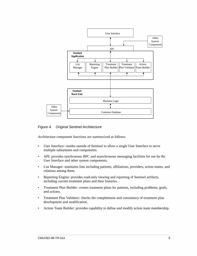
Figure 4. Original Sentinel Architecture
Architecture component functions are summarized as follows:
• User Interface: resides outside of Sentinel to allow a single User Interface to servemultiple subsystems and components.
• API: provides synchronous RPC and asynchronous messaging facilities for use by theUser Interface and other system components.
• List Manager: maintains lists including patients, affiliations, providers, action teams, andrelations among them.
• Reporting Engine: provides read-only viewing and reporting of Sentinel artifacts,including current treatment plans and their histories.
• Treatment Plan Builder: creates treatment plans for patients, including problems, goals,and actions.
• Treatment Plan Validator: checks the completeness and consistency of treatment plandevelopment and modification.
• Action Team Builder: provides capability to define and modify action team membership.

10 CMU/SEI-98-TR-014
• Business Logic: contains enterprise-defined business rules, including validation checksfor treatment plan development and logging triggers that manage change control ofsensitive data.
• Database: sentinel shares access to a common database with other subsystems andcomponents.
Step 2: Essential Capability DefinitionEssential Service/Asset Selection/ScenariosEssential services and assets represent critical system capabilities that must survive and beavailable during intrusions. Criticality is based on analysis of mission objectives, risks andconsequences of failure, and availability of alternatives. Such an analysis may result in selec-tion of any number of essential services and assets, and may stratify them into survivabilityclasses of varying criticality. The survivability analysis of the Sentinel subsystem was carriedout together with CWI personnel, and was based on the normal usage scenarios identified instep 1. The analysis resulted in selection of a single essential service, namely, NUS3, the ca-pability to view treatment plans. This service, more than any other, was deemed essential todelivery of mental health treatment because providers depend on real-time, on-demand accessto treatment plans in clinical situations, particularly in cases of medication or therapeuticproblems of an emergency or life-critical nature. The other normal usage scenarios could bepostponed for hours or even days in the event of system intrusion and compromise. Theanalysis also identified a single essential asset, namely, the treatment plans themselves. Pres-ervation of treatment plan integrity and confidentiality was deemed essential to meeting Sen-tinel mission objectives. The other Sentinel artifacts, such as action teams, affiliations, andproviders, could all be reconstructed or updated hours or days after intrusion with no irre-versible consequences.
Essential Component IdentificationEssential system components are those components that participate in delivery of essentialservices and preservation of essential assets. The execution trace of the NUS3 scenario re-vealed the reporting engine and the database components, as well as their supporting compo-nents and artifacts, are essential to maintaining the capability to perform the scenario. As es-sential assets, the integrity and confidentiality of treatment plans depends on databasecomponents for security and validation.
Step 3: Compromisable Capability DefinitionIntrusion Scenario SelectionBased on the system environment and assessment of intruder objectives and capabilities, thefollowing five intrusion usage scenarios (IUS) were selected as representative of the types ofattacks to which Sentinel could be subjected. Each scenario is preceded by an IUS numberand type of attack (shown in parentheses), and followed by a brief explanation:

CMU/SEI-98-TR-014 11
• IUS1 (Data Integrity and Spoofing Attack): An intruder swaps the patient identificationof two validated treatment plans.
Sentinel performs validation of treatment plans before entering them into the database. Inthis scenario, an intruder accesses the database server to corrupt treatment plans withoutusing the Sentinel client, but rather by spoofing a legitimate client.
• IUS2 (Data Integrity and Insider Attack): An insider uses other legitimate database clientsto modify or view treatment plans controlled by Sentinel.
The database security assumes that clients have exclusive write access to specificdatabase tables. While the IUS1 scenario attempts to access the database directly, thisscenario examines inappropriate access through other database clients.
• IUS3 (Spoofing Attack): An unauthorized user employs Sentinel to modify or viewtreatment plans by spoofing a legitimate user.
Some terminal access points for Sentinel are located in public areas, and hence are not asphysically secure as those in private offices. This scenario illustrates opportunistic use ofan unoccupied but logged-in terminal by an illegitimate user who spoofs the legitimatelogged-in user.
• IUS4 (Data Integrity and Recovery Attack): An intruder corrupts major portions of thedatabase, leading to loss of trust in validated treatment plans.
Scenarios IUS1 and IUS2 assume a sophisticated attacker who targets and recognizesspecific treatment plans, and modifies only a few fields. This scenario assumes a brute-force corruption of the database, leading to large-scale loss of trust and potential denial ofservice during massive recovery operations.
• IUS5 (Insider and Availability Attack): An intruder destroys or limits access to theSentinel software so it cannot be used to retrieve treatment plans.
This scenario could be as simple as removing the Sentinel software, or could involveattacks on the network or application ports to limit application access.
Compromisable Component IdentificationCompromisable system components are those components that can be accessed and poten-tially damaged by intrusion scenarios. The execution traces of the five IUS scenarios revealedthe following component vulnerabilities:
• IUS1: This scenario compromises the treatment plan component. There were no validitychecks made on treatment plans after the initial entry.
• IUS2: This scenario compromises the treatment plan component. The treatment planchanges might be consistent but made by an improper agent.
• IUS3: This scenario compromises the treatment plan component. The majority of systemusers would object to logging into the system repeatedly as a way to continually monitorthe validity of the user. The system had not considered those terminals which were inopen areas easily accessible by unauthorized users.

12 CMU/SEI-98-TR-014
• IUS4: This scenario compromises the treatment plan component. Database recoveryrequired higher priority with respect to operations.
• IUS5: All software components of the Sentinel subsystem are affected by this scenario.While there were implicit user requirements on availability, it had not been considered inthe architecture.
Step 4: Survivability AnalysisSoftspot Component IdentificationAs noted earlier, softspot components are those components that are both essential and com-promisable. The foregoing analysis shows that the (essential service) reporting engine com-ponent and the (essential asset) database treatment plan component can both be compromisedin a variety of ways. The survivability analysis focuses on the essential services and assetsthat these components provide in fulfilling the mission objectives of the system.
Resistance, Recognition, and Recovery AnalysisAnalysis of the three R’s resulted in the Survivability Map depicted in Table 1(ID stands foridentification, TP for treatment plan, UI for user interface, and DB for database). The rec-ommendations in Table 1 are annotated with reference numbers {1} to {6} that correlate withchanges to the architecture defined in Figure 5. Development of the table began by matchingeach intrusion scenario trace (created in step 3 above) to the softspot components. Each tracewas first checked for all current resistance (protection) components in the architecture thatwould increase the difficulty experienced by an intruder in reaching the softspots referencedin the trace. Because no detailed implementation information was available to identify spe-cific vulnerabilities in these resistance components, an assumption was made that any vulner-abilities in them would be found and corrected over time. The greater the resources availableto an intruder, however, the less time a resistance component will be completely effective.The current resistance components are described in the resistance column of the SurvivabilityMap for each scenario.
For the recognition column, a process similar to the resistance analysis was followed. To as-sess the effectiveness of current recognition components, a number of assumptions weremade and listed in the Survivability Map. For example, in scenario IUS3 in Table 1, there is adocumented assumption that a provider will become suspicious when there are a large num-ber of denied accesses to treatment plans reported to some party. If this assumption is notvalid, then there are no current recognition strategies associated with this scenario.
For the recovery column, assumptions were made regarding common database managementfacilities (standard backup and recovery of the database itself and version control of the Sen-tinel software). Table entries for current recovery strategies included these assumptions, sothat if in fact they are not satisfied in the final system, the recovery strategy will be less ef-fective than that described in the Survivability Map. However, the assumptions for the cur-rent recovery strategies take into account standard practice with regard to distributed databasesystems.

CMU/SEI-98-TR-014 13
Once all of the current resistance, recognition, and recovery strategies were identified, gapsand weaknesses were analyzed for common points in the architecture where a particular sur-vivability improvement could address multiple scenarios or multiple strategies. These high-leverage recommendations are listed in a consistent form and identified as a common rec-ommendation. Other gaps identified by a lack of an existing strategy in any of the resistance,recognition, or recovery columns were also addressed. For the resistance column, recommen-dations were made even where an existing resistance mechanism existed, as this mechanismcan be expected to degrade over time. Ultimately, it is up to the system architect to determinethe cost-benefit of implementing these recommendations. The Survivability Map can help anarchitect determine the impact of accepting risks associated with weaknesses in the resis-tance, recognition, or recovery columns, as these are correlated to the intrusion scenarios thataffect the essential services or assets of the system. In Table 1, a number of gaps and as-sumptions are identified in the current resistance, recognition, and recovery strategies. Ofparticular interest to an architect are those recommendations that deal with multiple intrusionscenarios. For example, adding a crypto-checksum to the validation of a treatment plan ad-dresses several scenarios.

14 CMU/SEI-98-TR-014
Intrusion Scenario Resistance Strategy Recognition Strategy Recovery Strategy
Current:Two passwords are re-quired for TP access.
Current:Logging of changes made toDB.Provider may recognize anincorrect TP.
Current:Built-in recovery in commer-cial DB.Backup and recovery schemedefined.
IUS1:
Intruder swaps the ID oftwo validated TPs.
Recommended:Implement strong authen-tication supported in asecurity API layer. {1}
Recommended:Add crypto-checksum whenTP is validated.{3} Verifycrypto-checksum when TP isretrieved. {4}
Recommended:Implement a recovery mode inthe user interface to supportsearching for and recoveringincorrect TPs. {1}
Current:Security model for DBfield access.
Current:None.
Current:Scrap data and start over, orfind an early backup and ver-ify each entry.
IUS2:
Outside agents exercise(legitimate) access toDB fields controlled bySentinel.
Recommended:Need to verify the securitymodel in light of moduleaddition and integration.
Recommended:Perform a validation on accessof a TP for verification. {2}Add crypto-checksum whenTP is validated.{3} Verify thischecksum when TP is re-trieved. {4}
Recommended:Scan DB for invalid crypto-checksums and/or invalid TPsand recover to last knowncorrect TP. {4}
Current:None. No timeout is speci-fied so that anyone canuse a logged in but va-cated terminal. However,intruder only has access tologged in user’s TPs
Current:None, except for unusualnumber of denied accesses toTPs as an intruder attempts tolocate particular TPs.
Current:Can get list of modified TPsthrough the spoofed userstransaction history. Manuallyrecover each modified record.
IUS3:
An unauthorized useremploys Sentinel tomodify or view TPs byspoofing a legitimateuser.
Recommended:Add a short logout timeoutfor any terminals in un-controlled areas (not phy-sician’s offices). {1}
Recommended:Add logging, access control,and illegal access thresholdsto the security API. {1}
Recommended:Develop a recovery procedureand support it in the UI. {1}
Current:Security model in the DBprotects data against cor-ruption.
Current:None, except when providerhappens to recognize a cor-rupted TP.
Current:Locate an uncorrupted backupor reconstruct TPs fromscratch.
IUS4:
Intruder corrupts DBleading to loss of trustin validated TPs. Recommended:
Implement live replicatedDB systems that crosscheck for validity (sup-ported in many commer-cial DB systems). {5}
Recommended:Add and check crypto-checksums on records in theDB. {3} {4}
Recommended:Reduce the backup cycle toquickly rebuild once a cor-rupted DB is detected. {5}
Current:Keep originals available.
Current:System doesn’t work.
Current:Reload the system from origi-nals.
IUS5:
Intruder destroys theSentinel software so itcannot be used to re-trieve TPs
Recommended:Keep a spare CD availablefor quick recovery
Recommended:None. Easy to detect this one.
Recommended:Fast recovery from CD.Create a small sub-system thatcan retrieve TPs while Senti-nel is down or being up-graded. {6}
Table 1. Sentinel Subsystem Survivability Map

CMU/SEI-98-TR-014 15
The modified architecture resulting from the Survivability Map analysis is depicted in Figure5, with additions and changes shown with dashed lines and shading. Many of the recommen-dations in the Survivability Map affect the same architectural component. To further illustratethe overlaps, reference number annotations {1} to {6} attached to the recommendations areincluded in the modified architecture. In this way, it was easy to determine which of the rec-ommendations addressed multiple intrusion scenarios. With limited resources to mitigatethese risks, this view of the recommendations can help the architect allocate resources tohigh-impact modifications of the architecture. As the modified architecture was formed toaddress the recommendations in the Survivability Map, several natural locations emerged inthe existing architecture where implementation of the recommendations could be localizedwith minimal impact to the overall system. This was primarily due to the functional decom-position used in the original architecture. It is also likely that the evaluation of the scenariosled to the formation of recommendations that were natural to the architecture, since in exe-cuting the scenarios over the architecture, the impact on individual modules was evident.
ListManager
ReportingEngine {2}
TP Builder -crypto-chk
{3}
TP Validator -crypto-chk
{4}
ActionTeam Builder
User Interface
SentinelApplication
SentinelBack End
Business Logic
Security {1}
Common Database - Replicated and Daily Backups {5}
API
OtherSystem
Components
OtherSystem
Components
MinimalUser
Interface
MinimalReporting Engine/TPs
IsolatedReportingSystem {6}
Security Layer {1}
Figure 5. Sentinel Architecture with Survivability Modifications
To support the essential service (treatment plan display) and asset (treatment plans) identifiedin the earlier stages of the process, a simple new component {6} was added outside the origi-nal architecture that could serve the purpose of retrieving treatment plans if the primary sys-tem should fail for any reason. With this external component, intrusion scenario IUS5 wasaddressed. This new component had minimal impact on the original architecture, since it

16 CMU/SEI-98-TR-014
identified a distinctly separate software program used to interface with the underlying data-base. It is possible, depending on the selection of the database system, that this small compo-nent could be included in the procurement of the software as a simple database retrieval pro-gram. In addition, to address the validation of treatment plans read from the database (notsimply saved to the database), there was a sequencing recommendation ({2}, {3}, and {4})that all data retrieved from the database would pass through the validation module to verifythe correctness of the crypto-checksum.
A proactive validation function was also recommended, whereby the validation modulewould retrieve treatment plans from the database during idle time to continuously validate thedata saved in the database against the saved crypto-checksums.
To address IUS3, it was desirable to add a security layer {1} to the architecture between theuser interface and the other parts of the Sentinel architecture. This provided a location formonitoring and logging activity between the user interface and the Sentinel subsystem. Thisis especially important if the recommendations on the user interface (documented in IUS1,IUS3, and IUS4) were not implemented (these were out of scope for the Sentinel develop-ment team). The security layer provides functionality for passing user credentials to the data-base for access control in addition to providing intrusion detection, timeout information, andother security-relevant functions.
Several of the recommendations did not address the view of the architecture presented inFigure 5 directly, but were concerned with the use of the architecture. For example, the rec-ommendation in IUS2 calling for the validation of the security model in the Sentinel backend system {5}. This is an example of an architectural requirement that is expressed in theSurvivability Map, but is difficult to capture in the common “topology” view of the architec-ture. These recommendations are mapped to specific components in the topology view; how-ever, the changes to these components are not evident in their implementation, but rather inthe process of their implementation.
In addition to architectural analysis, these survivability findings can also be reflected inmodifications to Sentinel requirements. The Mission Requirements Definition of step 1 re-vealed few specific survivability or security requirements for the Sentinel subsystem, otherthan requiring 1) validation of treatment plan data, 2) utilization of some security featuresbuilt into the standard login process and the database, and 3) a development strategy thatwould permit easy modification to add security features. Changes are needed at the highestlevel to two areas of the requirements. Under survivability conditions, there is a critical needfor providers to view treatment plans within a reasonable time.

CMU/SEI-98-TR-014 17
In addition, there is a need to protect the integrity of the treatment plans in the database.These high-level requirements might be stated as follows:
• The treatment plan data shall be viewable within xx seconds of request under nominalconditions. The treatment plan data shall be viewable within yy seconds (minutes) ofrequest during recovery.
• Resistance and recognition techniques shall be used to protect the integrity of thetreatment plan data under intrusion scenarios IUS1 through IUS5.
These requirements can be refined to encompass software, procedural, and hardware re-quirements. The software requirements might be:
• An emergency reporting system shall allow treatment plans to be viewed during recovery.
• Treatment plans shall be validated when they are read and written. If a treatment plan isinvalid, the last valid version of the treatment plan shall be recovered.
• Encrypted checksums shall be used to protect the integrity of the treatment plans.
• The selected database software shall support replication.
The procedural requirements might be:
• The Sentinel software shall be backed up on CD.
• Daily backups of the database shall be performed.
The hardware/operating system requirement might be:
• Workstations located in public areas shall have a short timeout based on inactivity. Thereshall be login access thresholds for incorrect logins.

18 CMU/SEI-98-TR-014

CMU/SEI-98-TR-014 19
4 Lessons Learned
The SNA method is under continuing development and additional case studies are planned.Lessons learned at this stage focus on the validity of the initial assumptions and objectives ofthe method, as well as refinements that can be explored in future case studies. The Sentinelcase study began with three assumptions:
• Survivability strategies could be organized in terms of resistance, recognition, andrecovery.
• The analysis should focus on early phases of the life cycle, specifically, on the missionrequirements, as they represent the essential services and assets of the system, and on thearchitecture, as it represents the components that must be survivable and the strategies forachieving survivability.
• The application logic rather than the system infrastructure should bear a significantportion of the responsibility for implementation of survivability strategies [Saltzer 84].
The case study supported these assumptions. Organization of survivability strategies in termsof resistance, recognition, and recovery was straightforward and easily communicated to thecustomer. Identification of essential services and assets was a critical step in limiting thescope of the analysis, as well as in reducing the number and scope of architectural revisionswhich the customer should consider. The Sentinel subsystem examined in this study was justentering its implementation phase; future studies should include a need to reengineer existingsystems.
The success of the SNA method depends on the effectiveness of the recommendations, thatis, achievement of a modified system that is by some set of measures more survivable. Ofequal importance is whether the customer can incorporate the recommendations into the ex-isting software development process, and thus be able to adopt the suggested changes. Be-cause the survivability recommendations for Sentinel concentrated on refining an existingarchitecture rather than requiring a redesign, they did satisfy this criterion.
While most of the recommendations focused on revisions to the application architecture, sev-eral suggested changes in design and implementation or in operations and procedures to sup-port survivability in the existing architecture. The study did raise some issues of extensibility,that is, could the proposed architecture support the functionality desired in later versions froma survivability perspective. Analysis of extensibility could be an important aspect of futurestudies. The recommendations produced in this study were able to take advantage of existing
20 CMU/SEI-98-TR-014
system features to support reliability and fault tolerance, such as the transactional support andrecovery mechanisms provided by the relational database.
While the study did not involve extensive distributed system requirements, it was neverthe-less fruitful to look for the design assumptions that might fail in a networked environment ormake recovery difficult. For example, a networked application might exhibit requirements forsupporting disconnected operations by clients, and thus exhibit an architecture that supports amessaging communications model. A future study might explore how to leverage that type ofarchitectural choice to support general survivability in the same way that this study leveragedsurvivability capabilities of the relational database infrastructure. In addition, the SNAmethod, artifacts, and lessons learned described in this case study report can be leveraged forsurvivability analysis of a variety of proposed and legacy DoD systems in diverse domains.These domains include distributed and networked command and control, integrated logistics,mission-specific, and real-time systems.

CMU/SEI-98-TR-014 21
5 Acknowledgements
The authors are pleased to acknowledge the contributions of David Fisher and Howard Lip-son of the CERT/CC to the definition of the SNA method.
The authors appreciate the support and cooperation of CarnegieWorks, Inc. in conducting thisstudy. Cindi Carbine of CWI provided valuable insights into Vigilant system objectives,structure, and operational environment. The authors also acknowledge the team that devel-oped the Sentinel subsystem prototype. The development was carried out as a studio projectin the Master of Software Engineering program at Carnegie Mellon University. Team mem-bers included Melissa Cheok, Ryan Soulier, Grama Srinivasan, Shinji Yamato, and IsabelYebra.
This report and the effort to produce it were sponsored by USAF Embedded Computer Re-sources Support Improvement Program (ESIP) and the U.S. Department of Defense.

22 CMU/SEI-98-TR-014

CMU/SEI-98-TR-014 23
References
[Ellison 97] Ellison, R. J.; Fisher, D. A.; Linger, R. C.; Lipson, H. F.; Longstaff,T.; and Mead, N. R. Survivable Network Systems: An EmergingDiscipline (CMU/SEI-97-TR-013, ADA341963). Pittsburgh, Pa.:Software Engineering Institute, Carnegie Mellon University, 1997.
[Linger 98] Linger, R. C.; Mead, N. R.; and Lipson, H. F. “Requirements Defi-nition for Survivable Network Systems” [online]. Available WWW:<http://www.cert.org/research/req-paper/meadframe.html> (1998).
[Lipson 97] Lipson, H. F. and Longstaff, T., eds. Proceedings of the 1997 Infor-mation Survivability Workshop [online]. Available WWW:<http://www.cert.org/research/isw97_hypertext/front_page.html>(1997).
[Mendiratta 96] Mendiratta, V. “Assessing the Reliability Impacts of SoftwareFault-tolerance Mechanisms.” Proceedings of Seventh InternationalSymposium on Software Reliability Engineering, October 30–No-vember 2, 1996, White Plains, N.Y. Los Alamitos, Ca.: IEEE Com-puter Society Press, 1996.
[Musa 87] Musa, J.; Iannino, A.; and Okumoto, K. Software Reliability: Meas-urement, Prediction, and Application. New York: McGraw-Hill,1987.
[Saltzer 84] Saltzer, J. H.; Reed, D.P.; and Clark, D.D. “End-to-End Argumentsin System Design.” ACM Transactions in Computer Systems 2, 4(November 1984), 277-288.
[Summers 97] Summers, Rita C. Secure Computing: Threats and Safeguards. NewYork: McGraw-Hill, 1997.

24 CMU/SEI-98-TR-014

REPORT DOCUMENTATION PAGE Form ApprovedOMB No. 0704-0188
Public reporting burden for this collection of information is estimated to average 1 hour per response, including the time for reviewing instructions, searching existing data sources, gathering andmaintaining the data needed, and completing and reviewing the collection of information. Send comments regarding this burden estimate or any other aspect of this collection of information,including suggestions for reducing this burden, to Washington Headquarters Services, Directorate for information Operations and Reports, 1215 Jefferson Davis Highway, Suite 1204, Arlington,VA 22202-4302, and to the Office of Management and Budget, Paperwork Reduction Project (0704-0188), Washington, DC 20503.1. AGENCY USE ONLY (LEAVE BLANK) 2. REPORT DATE
September 19983. REPORT TYPE AND DATES
COVERED
Final4. TITLE AND SUBTITLE
A Case Study in Survivable Network System Analysis
5. FUNDING NUMBERS
C — F19628-95-C-0003
6. author(s)
R.J. Ellison; R.C. Linger; T. Longstaff; N.R. Mead
7. PERFORMING ORGANIZATION NAME(S) AND ADDRESS(ES)
Software Engineering InstituteCarnegie Mellon UniversityPittsburgh, PA 15213
8. PERFORMING ORGANIZATIONREPORT NUMBER
CMU/SEI-98-TR-014
9. SPONSORING/MONITORING AGENCY NAME(S) AND ADDRESS(ES)
HQ ESC/DIB5 Eglin StreetHanscom AFB, MA 01731-2116
10. SPONSORING/MONITORINGAGENCY REPORT NUMBER
ESC-TR-98-014
11. SUPPLEMENTARY NOTES
12.A DISTRIBUTION/AVAILABILITY STATEMENT
Unclassified/Unlimited, DTIC, NTIS12.B DISTRIBUTION CODE
13. ABSTRACT (MAXIMUM 200 WORDS)
This paper presents a method for analyzing the survivability of distributed network systems and an example ofits application. Survivability is the capability of a system to fulfill its mission, in a timely manner, in the presenceof attacks, failures, or accidents. Survivability requires capabilities for intrusion resistance, recognition, and re-covery. The Survivable Network Analysis (SNA) method builds on the Information Security Evaluation previ-ously developed by permitting assessment of survivability strategies at the architecture level. Steps in the SNAmethod include system mission and architecture definition, essential capability definition, compromisable ca-pability definition, and survivability analysis of architectural softspots that are both essential and compromis-able. Intrusion scenarios play a key role in the method. SNA results are summarized in a Survivability Mapwhich links recommended survivability strategies for resistance, recognition, and recovery to the system archi-tecture and requirements. This case study summarizes the application and results of applying the SNA methodto a subsystem of a large-scale, distributed healthcare system. The study recommended specific modificationsto the subsystem architecture to support survivability objectives. Positive client response to study recommen-dations suggests that the method can provide significant added value for ensuring survivability of system op-erations. As a result of this case study, the SNA method, artifacts, and lessons learned will be available to ap-ply architectural analysis for survivability to proposed and legacy DoD distributed systems.
15. NUMBER OF PAGES
24 pp.14. SUBJECT TERMS
architecture analysis, essential services, intrusion scenarios, network systems,survivability, Survivability Map
16. PRICE CODE
17. SECURITY CLASSIFICATIONOF REPORT
UNCLASSIFIED
18. SECURITY CLASSIFICATIONOF THIS PAGE
UNCLASSIFIED
19. SECURITY CLASSIFICATIONOF ABSTRACT
UNCLASSIFIED
20. LIMITATION OF ABSTRACT
ULNSN 7540-01-280-5500 Standard Form 298 (Rev. 2-89)
Prescribed by ANSI Std. Z39-18298-102
![Survivable networks, linear programming relaxations and ...web.mit.edu/dbertsim/www/papers...problem [14, 11] or the generalized Steiner problem [37]. The survivable network design](https://static.fdocuments.in/doc/165x107/5f64a522276b455b0635dff4/survivable-networks-linear-programming-relaxations-and-webmitedudbertsimwwwpapers.jpg)