CASE STUDY : 1 :TED IN KUANTAN NURBAJTEE BINTI ...
24
PERPUSTAKAAN UMP 11111111111 CASE STUDY : 1 0000072607 :TED IN KUANTAN NURBAJTEE BINTI MOHAMAD FAUZI A thesis submitted in partial fulfillment of the requirements for the award of the degree of Bachelor of Civil Engineering Faculty of Civil Engineering & Earth Resources University Malaysia Pahang JUNE 2012
Transcript of CASE STUDY : 1 :TED IN KUANTAN NURBAJTEE BINTI ...

PERPUSTAKAAN UMP
11111111111 CASE STUDY : 1
0000072607 :TED IN KUANTAN
NURBAJTEE BINTI MOHAMAD FAUZI
A thesis submitted in partial fulfillment of the
requirements for the award of the degree of
Bachelor of Civil Engineering
Faculty of Civil Engineering & Earth Resources
University Malaysia Pahang
JUNE 2012

v
ABSTRACT
In the construction of the man-made or natural channel, there are various problems that
should be taking into consideration especially in the design of the hydraulic open
channel. The presence of high flow velocity in open channel can destroy the function of
the structure due to erosion and scouring along the channel bed. As a result,
maintenance work will be costly. However, this problem can be overcome by reducing
the flow velocities in the channel. In order to achieve this aim, an energy dissipater
structure is proposed to be constructed in the channel. The objective of this study is to
define the capability of discharge channel in the effect of various types of discharge
channels, characteristic of flow and flow condition in stepped channel. This study is
conducted in Kuantan area. There are five different types of discharge channel used in
this study, that is channel without stepped, trapezoidal stepped channel, parabolic
stepped channel, rectangular stepped channel and rectangular stepped channel with rock
surface. From the graph plotted, a relationship between energy dissipation and different
types of channel were gained. The results indicate that rectangular stepped channel with
rock surface dissipates more energy compared to other types of discharge channels.
Results also show that as the velocity of water increased, the energy dissipation is
decreased. Generally, this study has proven that the stepped structure is effective in
dissipate energy compared to channel without stepped in the hill area.

vi
ABSTRAK
Pembinaan sistem saluran buatan manusia atau semulajadi sering mengalami pelbagai
masalah dan perlu diberi perhatian terutamanya semasa mereka bentuk sistem saluran
terbuka. Kehadiran aliran halaju tinggi dalam saluran terbuka boleh memusnahkan
fungsi struktur yang disebabkan oleh hakisan didasar saluran. Hasilnya, ia akan
melibatkan kos yang tinggi untuk kerja penyelenggaraan. Walaubagaimanapun, masalah
ini boleh diatasi dengan mengurangkan halaju aliran. Bagi mencapai matlamat ini,
struktur pelesap tenaga perlu dibina di setiap saluran. Objektif kajian ini adalah untuk
mengkaji keupayaan saluran terbuka dengan perubahan jenis-jenis saluran, ciri-ciri
profit aliran dan keadaan aliran didalam saluran bertangga. Kajian ini dijalankan di
kawasan Kuantan. Terdapat lima jenis saluran yang digunakan dalam kajian ini, iaitu
saluran tanpa tangga, saluran bertangga berbentuk trapezoid, saluran bertangga
berbentuk parabola, saluran bertangga berbentuk segi empat dan saluran bertangga
berbentuk segi empat dengan permukaan berbatu. Hubungan antara pelesapan tenaga
dan jenis yang berlainan saluran boleh ditentukan dengan memplot graf. Keputusan
kajian ini menunjukkan bahawa saluran bertangga berbentuk segi empat dengan
permukaan berbatu melesapkan lebih banyak tenaga berbanding dengan jenis saluran
terbuka yang lain. Keputusan kajian ini turut menunjukkan bahawa apabila halaju air
meningkat, lesapan tenaga akan menurun. Secara umumnya, kajian ini telah
membuktikan bahawa struktur bertangga lebih berkesan dalam melesapkan tenaga
berbanding dengan saluran tanpa bertangga di kawasan bukit.

Vll
TABLE OF CONTENTS
CHAPTER TITLE PAGE
DECLARATION ii
DEDICATION iii
ACNOWLEGDMENT iv
ABSTRACT v
ABSTRAK vi
TABLE OF CONTENTS vii
LIST OF TABLES x
LIST OF FIGURES xi
LIST OF SYMBOLS xiii
1 INTRODUCTION
1.1 Background of Study 1
1.2 Problem Statement 2
1.3 Objectives 3
1.4 Scope of Study 3
1.5 Significant of Study 4
2 LITERATURE REVIEW
2.1 Introduction 5
2.2 Open channel 7
2.3 Type of Flow 7
2.4 States of Flow 8
2.4.1 Effect of Gravity 8
2.4.2 Effect of Viscosity 9
2.5 Velocity Flow 9
2.6 Energy Dissipater Structure 10
2.7 Shape and Type of Discharge Channel 11

3
2.7.l Channel without Stepped
2.7.2 Stepped Channel 2.8 Local Phenomena
2.8.1 Hydraulic Jump
2.8.2 Hydraulic Drop 2.9 Flow Condition in Stepped Channel
2.9.1 Nappe F low
2.9.2 Onset of Skimming Flow
2.9.3 Skimming Flow 2.9.4 Hypothesis of Flow Condition in Stepped
Channel 2.10 Energy Dissipation in Discharge Channel
METHODOLOGY
3.1 Introduction
3.2 Selection of Research Location
3.3 Early Review of Research Location
3.4 On-sites Data
3.5 Procedure
3.5.1 Procedure on the Data Collection for Discharge Channel
3.6 The governing equation
3.7 Data Form
RESULT AND DISCUSSION
4.1 Introduction
4.2 Measurement of Flow Rate
4.3 Data Observation
4.4 Data Analysis
4.4.1 Channel without Stepped
4.4.2
4.4.3
Trapezoidal Stepped Channel
Parabolic Stepped Channel
11
12
13
13
15
16
17
17
18
20
26
28
30
33
33
36
37
38
39
41
42
42
46
46
47
48
viii

4.4.4 Rectangular Stepped Channel
4.4.5 Rectangular Stepped Channel with Rock Surface
4.5 Comparison between five Different Type of Discharge Channel
4.6 Characteristic of Flow Profile
4.7 Flow Condition in Stepped Channel
4.8 Discussion
5 CONCLUSION AND RECOMMENDATIONS
5.1 Conclusion
5.2 Recommendation
REFERENCES
APPENDICES
50
51
52
53
57
58
60
62
63
65
ix

x
LIST OF TABLES
Table No Page
2.1 Summary of hydraulic modeling related to stepped channel 24
3 .1 Data form 40
4.1 Experiment results for channel without stepped 46
4.2 Experiment results for trapezoidal stepped channel 47
4.3 Experiment result for parabolic stepped channel 49
4.4 Experiment result for rectangular stepped channel 50
4.5 Experiment result for rectangular stepped channel with rock surface 51
4.6 Flow condition in stepped channels 57

xi
LIST OF FIGURES
Figure No. Page
2.1 Stepped channel that usually seen in hill area 6
2.2 Old stepped weir (dam) in Akarnania 6
2.3 Open channel flow 7
2.4 One of Alqueva dam chute spillway, in Portugal 11
2.5 Trapezoidal stepped channel 12
2.6 Rectangular stepped channel 12
2.7 Parabolic stepped channel 13
2.8 Side view of hydraulic jump 14
2.9 Hydraulic jump phenomenon 14
2.10 Hydraulic drop 15
2.11 Sketch of nappe flow and skimming flow 16
2.12 Parameter defining the step geometry 19
2.13 Energy dissipation for 8, 10, 20 and 30 stepped 26
3.1 Flow chart of study 29
3.2 Channel without stepped 30
3.3 Trapezoidal stepped channel 30
3.4 Rectangular stepped channel 31
3.5 Parabolic steooed channel 31
3.6 Rectangular stepped channel with rock surface 32
3.7 Current meter 34
3.8 Measuring tape 34
3.9 Dimension of channel is taken using measuring tape 37
3.10 Velocity of flow is taken using current meter 37

xji
3.11 Depth of flow is taken using ruler 38
4.1 The relationship of flow rate, Q (m3/s) and energy dissipation for 47 channel without stepped
4.2 The relationshjp of flow rate, Q (m3/s) and energy dissipation for 48 trapezoidal stepped channel
4.3 The relationship of flow rate, Q (m3/s) and energy russipation for 49 parabolic stepped channel
4.4 The relationship of flow rate, Q (m3/s) and energy dissipation for 51 rectangular stepped channel
4.5 The relationship of flow rate, Q (m3/s) and energy dissipation for 52 rectangular stepped channel with rock surface
4.6 The relationship of flow rate, Q (m3/s) and energy dissipation for five 53 different cases
4.7 The relationship of flow rate, Q (m3/s) and Froude Number for channel 54 without stepped
4.8 The relationship of flow rate, Q (m3/s) and Froude Number for 55 trapezoidal stepped channel
4.9 The relationship of flow rate, Q (m3/s) and Froude Number for 55 parabolic stepped channel
4.10 The relationship of flow rate, Q (m3/s) and Froude Number for 56 rectangular stepped channel
4.11 The relationship of flow rate, Q (m3/s) and Froude Number for 56 rectangular stepped channel with rock surface

xiii
LIST OF SYMBOLS
Fr Froude Number
v Velocity of flow
y Hydraulic depth
g Acceleration due to gravity = 9.81 mis
Re Reynold's Number
L Length
u Kinematic viscosity (u =µIp)
E Flow energy
~ Energy losses
0 Slope
h Height of stepped
Q Flow rate
A Flow area
B Width of stepped
Ye Critical depth
Eo Energy at the end of channel
a Kinetic energy correction factor
N Number of stepped

CHAPTER!
INTRODUCTION
1.1 Background of Study
Discharge channels are usually constructed in hill area especially in side of
highway. These discharge channels are designed to reduce the velocity flows that move
from the high area, also to drain the runoff to minimize water absorption in soil. Soil
erosion and landslides may seen due to high water absorption in soil is high. Discharge
channels design has been used for a wide range of functions, including dams, overflow
channels, public drainage system and many more which aim to reduce the velocity and
dissipate energy along the channels.
They also constructed in various shapes. It depends on the slope, type of soil and
influences by the rainfall intensity. Design of channels are varies depending on height
and slope. In Malaysia, the common shapes of channel that normally constructed are
from rectangular, trapezoidal and parabolic shapes as these shapes are the most ideal
and easy to maintain. Moreover, rectangular, trapezoidal and parabolic channels are
relatively easy to construct and more economical ..

2
The main role of discharge channels is to drain and convey the water from one
place to another. Whereas, discharge channels is designed as energy dissipater of high
velocity flows. Another purpose in constructing the discharge channel is to improve the
water quality and for the aesthetic view. The flow conditions in stepped channel such as
skimming flow and nappe flow also can be observed. The formation of skimming flow
and naope flow depend on the change of step height, the discharge and the channel
slope.
1.2 Problem Statement
Normally, problem occurs when the downstream velocity is high. Other than
that, water that overtopped the roadway affects the damage system due to erosion. This
can be observed after a few years been operated. This problem often occurs at the
channels end defect such as crack and break can easily be found in culverts that
discharge water for rivers and wetlands.
Besides that, another common problem normally occurs is when the channel is
unable to accommodate the volume of water. This normally happens in the area with a
rapid growth environment. Moreover, with the high volume of water flow, there will be
a formation of scour at downstream of a discharge channel due to high velocity that
creates hydraulic jump phenomenon. The water will spill out from the channel, due to
the above mentioned defect; some amount of water will be absorbed by the soil and
reduced the slope stability.
Therefore, this work focused on the study of how is important to provide a
proper design of discharge channels. Otherwise, flash flood or overflow of water to the
3
roads may happen repeatedly. This will cause damage to the road and difficulties for the
road users and the authorities.
1.3 Objectives of the Study
The objectives of this research are as:
i. To study the capability of energy dissipater in discharge channels in the effect of
changes types of discharge channels.
ii. To identify the characteristic of flow profile for five different type of discharge
channel.
m. To study the flow condition in stepped channel.
1.4 Scope of Study
This study focuses on the aspect of flowing water in discharge channels in hill
area. The channel without stepped, trapezoidal stepped channel, parabolic stepped
channel, rectangular stepped channel and rectangular stepped channel with rock surface
are the types of the selected in this study.
The selected sites are in Kuantan area where there are numbers of discharge
channel constructed along the hill area. Five different types of drain system will be
conducted with the different on stepped height and channel slope. Observation on the
flow profile will be done during heavy rain.

4
1.5 Significant of study
The significant of this study is to give more exposure to the future engineers to
design the suitable channels in slope area. It will give opportunity for engineers to
evaluate the channels that should be use in sloping area based on the data obtained.
Moreover, the important of this study is to ensure that the energy dissipated, at
the downstream is smaller compared to the energy in the upper channel. Besides that, it
is hope that this study will also help and give ideas to engineers to assess the
effectiveness of stepped channel and choose the best form of geometric design.
Furthermore, it is hope that this work gives clearer information on the differences
between channels without stepped and stepped channel. Indeed, damage to the channels
structure can be avoided by selecting the most effective form of design. Hopefully, this
study will help the researches in the future.

5
CHAPTER2
LITERATURE REVIEW
2.1 Introduction
Stepped channel is the channel that has series of stepped on the face of channel.
The stepped on this channel can dissipate amount energies carried by the water that
flow along the channel. This channel is intended to reduce the velocity of water that
flow along the channel.
A stepped channel has been used as an energy dissipater of high velocity in
steep slope. According to Chanson.H (2001-2002), the stepped spillways, weirs and
channels have been used for over 3500 years since the first structure built in Greece and
Crete. The stepped design is recognised for its energy dissipation that required in
preventing scour and erosion of the invert and the banks as shown in figure 2.1.

6
Fieure 2.1: Stepped channel that usually seen in hill area.
Moreover, the stepped channel might be utilized for an aesthetic view.
According to Chanson.H (200 l-2002), the expertise on stepped spillways design was
spread around the Mediterranean area by Romans, Muslims and Spaniard successively.
Although the early stepped cascades were built in cut-stone masonry or timber, a wider
range of construction materials were introduced during 19th century. During 16th to 18th
centuries, numerous of 'Grandes Cascades' were built for aesthetic purpose. Figure 2.2
shows the old stepped weir been used in early BC1300.
Figure 2.2: Old stepped weir (dam) in Akamania, Greece B.C. 1300

7
2.2 Open channel
Open channel flow is also known as a free surface flow. A free surface is
subjected to atmospheric pressure. According to Chow.V.T. (2008), open channel flow
is a branch of hydraulic, is a type of liquid flow within a conduit with a free surface,
known as a channel.
A diagram for open channel flow is shown in figure 2.3. This is simplified by
assuming parallel flow with a uniform velocity distribution and that the slope of the
channel is small. In this case the hydraulic gradient is the water surface as the depth of
water corresponds to the piezometric height. Flow conditions in open channels are
complicated by the position of the free surface which will change with time and space.
2.3 Type of flow
Energy line _ . -- .:.._y-----
Water -------------surface --
Channel bed ~-:------1 -
ht
v2t2g
y
2 z
Figure 2.3: Open channel flow

8
Open channel flow can be classified and described in various ways based on the
changed in flow depth with respect to time and space.
Jn a time as a criterion, flow can be divided into two types that are steady flow
and unsteady flow. In steady flow, the depth of flow does not change over time, or if it
can be assumed to be constant during the time interval under consideration. If the depth
of flow does change with time, the flow is considered as unsteady flow.
In a space as a criterion, flow can be divided into uniform flow and varied flow.
Uniform flow is happen when the depth of flow is the same at every section of the
channel. Uniform flow can be steady or unsteady, depending on whether or not the
depth changes with time. Varied flow is happen when the depth of flow changes along
the length of the channel.
2.4 States of flow
2.4.1 Effect of Gravity
Froude number is a dimensionless number defined as the ratio of characteristic
velocity to a gravitational wave velocity. Froude number also may define as the ratio of
a body's inertia to gravitational forces. Froude Number is written as;
where,
V =velocity of flows (mis)
v Fr=--
jgy (2.1)
9
y =hydraulic depth (m)
g =acceleration due to gravity
When Froude Number is less than 1.0, the flow is classified as subcritical flow.
It is called critical flow when Froude Number is equal with 1. If Froude Number is
greater than 1, the flow is supercritical flow. When the supercritical flows meets the
subcritical flows, and then the hydraulic jumps will occurred.
2.4.2 Effect of Viscosity
Reynolds number, Re is a dimensionless number that gives a measure of the
ration of inertial force to viscous forces. Reynolds number is defined by;
where,
v = mean velocity (mis)
L = length of fluid (m)
vL Re=-
v
u =kinematic viscosity (u =µIp) (m2/s)
(2.2)
For an open channel the limits for each type of flow become laminar flow when
the Reynolds Number is less than 500. It is consider as turbulent flow when the
;Reynolds Number is greater than 12500. It is called transitional flow when 500 <Re<
12 500.
2.5 Velocity Flow
10
Velocity is the total flow rate per unit area of channel section or total distance
per unit time where the velocity is expressed in unit mis. Flow is reached high velocity
if water is passing through a narrow section along the channel where the capacity of
water is larger than the channel area.
According to Amat Sairin Demun in his book ' Hidraulik Saluran Terbuka'
(1997), when the water driven at high velocity a lower zone of velocity, the water level
immediately increased followed by violent turbulence, whirlpool and wave. This is
called as hydraulic jump. Hydraulic jump usually occur when the supercritical flows
meets the subcritical flows. There is no jump happen if the water flows below the
critical speed. For the initial flow speed which is not significantly above the critical
speed, only an undulating wave in water will appear.
2.6 Energy Dissipater Structure
Energy dissipater is a structure to reduce the fast moving flow, in order to
prevent erosion at the downstream channel.Water flow along the channel is driven by
the gravitational force. Therefore, with the increasing of height in stepped channel, the
magnitude of the flow velocity would be large. This may produce a very high kinetic
energy which can erode the banks and downstream channel gradually and in the long
term could damage the structure itself. To prevent this from happen, the energy need to
be reduced. This can be done with the construction of energy dissipater structure along
the channel.
According to Locher and Hsu (1984) the energy dissipater structure is a
structure that can change the flow velocity as it is able to reduce the high kinetic energy
produced from the critical speed to low energy with a slower flow. Generally, the
11
energy dissipater structure is used in each section which has high velocity either in the
upstream or downstream flow.
2.7 Shape and Type of Flood Discharge Channel
There are various type of structures have been design for the purpose to reduce
the very high velocity flow in sloped area. Structure that commonly found in sloping
area is channel without stepped and stepped channel.
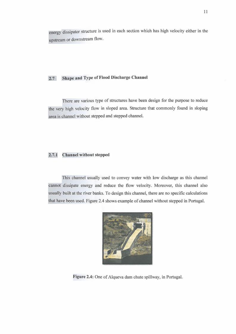
2.7.1 Channel without stepped
This channel usually used to convey water with low discharge as this channel
cannot dissipate energy and reduce the flow velocity. Moreover, this channel also
usually built at the river banks. To design this channel, there are no specific calculations
that have been used. Figure 2.4 shows example of channel without stepped in Portugal.
Figure 2.4: One of Alqueva dam chute spillway, in Portugal.

12
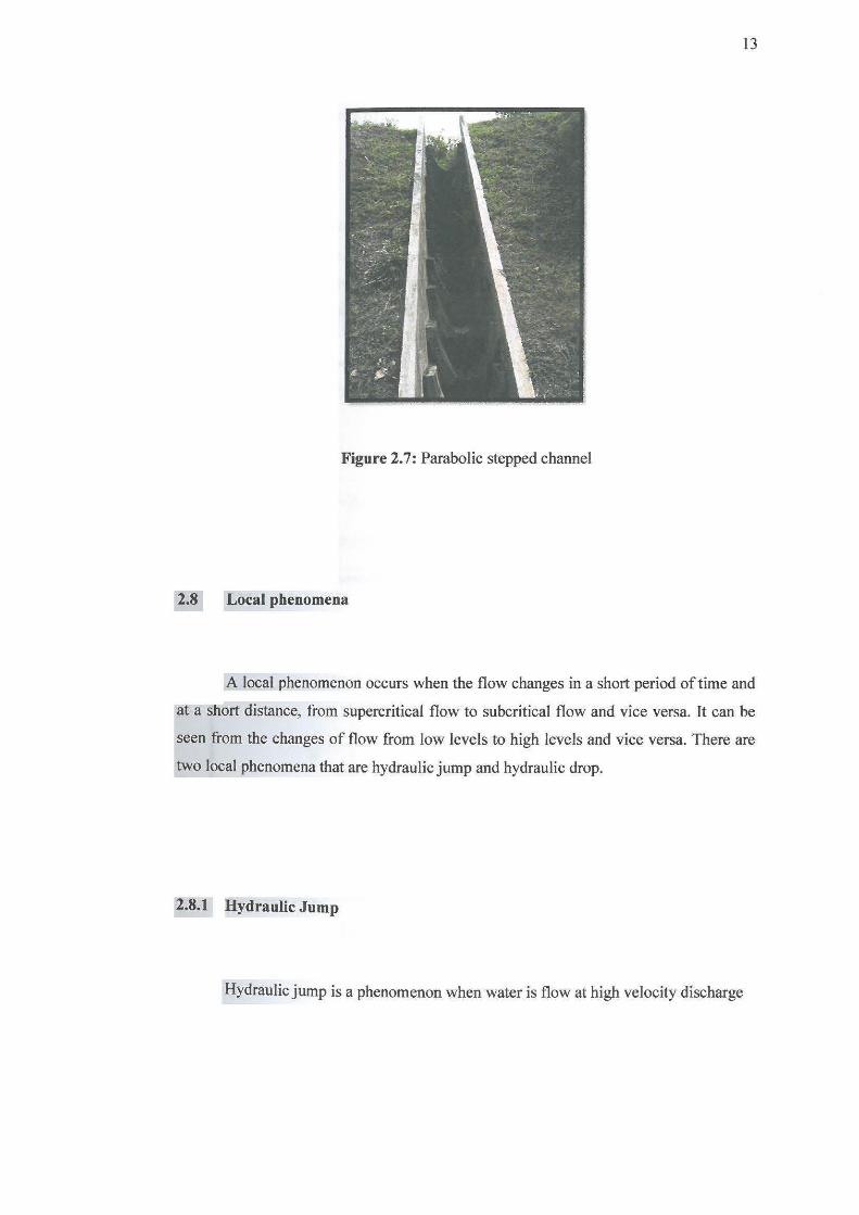
2. 7 .2 Stepped Channel
Stepped channel can be divided into five types, trapezoidal stepped channel as
shown in figure 2.5, rectangular stepped channel as shown in figure 2.6, parabolic
stepped channel as shown in figure 2.7, circular stepped channel and triangular stepped
channel.
Figure 2.5: Trapezoidal stepped channel
Figure 2.6: Rectangular stepped channel
13
Figure 2.7: Parabolic stepped channel
2.8 Local phenomena
A local phenomenon occurs when the flow changes in a short period of time and
at a short distance, from supercritical flow to subcritical flow and vice versa. It can be
seen from the changes of flow from low levels to high levels and vice versa. There are
two local phenomena that are hydraulic jump and hydraulic drop.
2.8.1 Hydraulic Jump
Hydraulic jump is a phenomenon when water is flow at high velocity discharge

14
into a zone of lower velocity, a rather abrupt rise occurs in the surface of water as
de ned in figure 2.8.
Hydraulic jump occur when the flow of water is change from the supercritical
flow to a subcritical flow, in which when the height increase, the velocity will decrease.
Hydraulic jump does not occur from subcritical to supercritical flow. Hydraulic jump
for stepped channel is shows in figure 2.9.
Higher velocity
Upstream
supercritical depth
t
Hydraulic Jump turbulence
--~-~
critical depth
conjugate depths
Slower velocity
Downstream
subcritical depth
Figure 2.8: Side view of hydraulic jump (flow is from left to right)
v2 _I_ lg
Energy
_______ y_ -- - ---
Figure 2.9: Hydraulic jump phenomenon