
Case Studies in Geotechnical Engineering Constructions
29
INVITED PAPER Case Studies in Geotechnical Engineering Constructions B. R. Srinivasa Murthy Received: 27 December 2012 / Accepted: 28 December 2012 / Published online: 20 January 2013 Ó Indian Geotechnical Society 2013 Abstract The enormous growth in the geotechnical activity in the country has resulted in slackening of the quality in all the three aspects of investigation, design and constructions endangering the safety of structures. The geotechnical engineering practice has now reached a stage of scientific maturity where many innovative solutions can be provided to solve field problems which had not been possible earlier. In the following paper case studies per- taining to each of the deficiencies of geotechnical activities have been reported. Keywords Case history Investigation deficiency Innovative solutions Reinforced earth Soil nailing Under-slab drainage Introduction Innovative geotechnical solutions to field problems more often than not do not follow the standard codes of practice. In fact the codes may follow after successful implemen- tation of such innovative solutions. One such example is the reinforced earth concept by Henry Vidal [1] which has been identified as the most innovative concept of last century in Civil Engineering Constructions. The recent increase in the rate of urbanization has thrust on the geo- technical engineers many new challenges such as deep excavations, poor and marginal foundation soils and underground constructions. The conventional solutions may be risky and cost prohibitive. Further these challenges have brought in many new and inexperienced players into the fields of geotechnical investigation, design and con- struction. This has resulted in the quality deficiency of each aspect, prohibitive cost and endangered the safety of the structure. The following article is aimed at highlighting the deficiencies in the above three activities which affected the safety of the structures. Some cost effective and innovative solutions for rectification are presented. Deficiency in the Geotechnical Investigations and Poor Selection of Foundations This is about a multistory hotel building in Chennai. The construction of the hotel building of size 18 m 9 36 m in plan with two basements, ground floor, mezzanine floor and nine upper floors was started in 1986 and was to be completed in 1991 (Fig. 1). The lifts were ordered and the lift manufacturer marked plumb lines on the lift well walls. After 3 months, when installation of the cage started a recheck of the plumb lines indicated that the originally marked lines were out of plumb by more than 75 mm. This created panic among all the players. Prof. A. Sridharan and the author were requested to be the Consultants to examine and investigate the problem and to provide suitable solu- tion. The owners were requested to provide the details of soil investigation reports, structural design basis report from the structural consultants and the as built structural drawings. From the available geotechnical report it was clear that the investigation had been carried out to a maximum depth of 3.0 m and at only two locations and recommendation of the SBC was 12 t/m 2 at 3 m depth. But the actual con- struction with two basements, the foundation level was at 5.4 m from the original ground level. The structural B. R. Srinivasa Murthy (&) 255, Sridhara, 4th Cross, II Block, RMV II Stage, Bangalore 560094, India e-mail: [email protected] 123 Indian Geotech J (January–March 2013) 43(1):1–29 DOI 10.1007/s40098-012-0038-y
Transcript of Case Studies in Geotechnical Engineering Constructions
INVITED PAPER
Case Studies in Geotechnical Engineering Constructions
B. R. Srinivasa Murthy
Received: 27 December 2012 / Accepted: 28 December 2012 / Published online: 20 January 2013
� Indian Geotechnical Society 2013
Abstract The enormous growth in the geotechnical
activity in the country has resulted in slackening of the
quality in all the three aspects of investigation, design and
constructions endangering the safety of structures. The
geotechnical engineering practice has now reached a stage
of scientific maturity where many innovative solutions can
be provided to solve field problems which had not been
possible earlier. In the following paper case studies per-
taining to each of the deficiencies of geotechnical activities
have been reported.
Keywords Case history � Investigation deficiency �Innovative solutions � Reinforced earth � Soil nailing �Under-slab drainage
Introduction
Innovative geotechnical solutions to field problems more
often than not do not follow the standard codes of practice.
In fact the codes may follow after successful implemen-
tation of such innovative solutions. One such example is
the reinforced earth concept by Henry Vidal [1] which has
been identified as the most innovative concept of last
century in Civil Engineering Constructions. The recent
increase in the rate of urbanization has thrust on the geo-
technical engineers many new challenges such as deep
excavations, poor and marginal foundation soils and
underground constructions. The conventional solutions
may be risky and cost prohibitive. Further these challenges
have brought in many new and inexperienced players into
the fields of geotechnical investigation, design and con-
struction. This has resulted in the quality deficiency of each
aspect, prohibitive cost and endangered the safety of the
structure. The following article is aimed at highlighting the
deficiencies in the above three activities which affected the
safety of the structures. Some cost effective and innovative
solutions for rectification are presented.
Deficiency in the Geotechnical Investigations and Poor
Selection of Foundations
This is about a multistory hotel building in Chennai. The
construction of the hotel building of size 18 m 9 36 m in
plan with two basements, ground floor, mezzanine floor
and nine upper floors was started in 1986 and was to be
completed in 1991 (Fig. 1). The lifts were ordered and the
lift manufacturer marked plumb lines on the lift well walls.
After 3 months, when installation of the cage started a
recheck of the plumb lines indicated that the originally
marked lines were out of plumb by more than 75 mm. This
created panic among all the players. Prof. A. Sridharan and
the author were requested to be the Consultants to examine
and investigate the problem and to provide suitable solu-
tion. The owners were requested to provide the details of
soil investigation reports, structural design basis report
from the structural consultants and the as built structural
drawings.
From the available geotechnical report it was clear that
the investigation had been carried out to a maximum depth
of 3.0 m and at only two locations and recommendation of
the SBC was 12 t/m2 at 3 m depth. But the actual con-
struction with two basements, the foundation level was at
5.4 m from the original ground level. The structural
B. R. Srinivasa Murthy (&)
255, Sridhara, 4th Cross, II Block, RMV II Stage,
Bangalore 560094, India
e-mail: [email protected]
123
Indian Geotech J (January–March 2013) 43(1):1–29
DOI 10.1007/s40098-012-0038-y

consultant had extrapolated the depth effect to adopt a safe
bearing pressure of 18 t/m2. The structural design basis
report indicated very conservative approach had been
adopted for the structural designs. The structural distribu-
tion of foundations is presented in Fig. 2. It is totally
unconventional with combined strip footings and rafts
randomly arranged. The structural design basis report and
the drawings indicated that the total load on the foundation
will be more than 18 t/m2 even with complete raft foun-
dation. A detailed analysis of loads on all columns and
footings indicated that the intensity of pressure varies from
14 t/m2 to more than 20 t/m2 under different footings.
Analysis and Solution
A detailed leveling survey was conducted around the
building and plumb measurements were taken on all the four
sides. It was noticed that the building has tilted diagonally
along DB diagonal of length of about 40 m by more than
250 mm while along the diagonal AC, there was no signifi-
cant difference. But between D and C corners and A and B
corners, the tilting was of about 125 mm. It was decided to
get soil investigations done again at four corners of the
building to a depth of 16 m from the ground level which
could give the ground characteristics to a depth of 10 m
below the footing level. Figure 2 provides the locations of
the 4 bore holes A, B, C and D with reference to the
building. The soil profile indicated the presence of water
table at the footing level of about 5.5 m below the ground
level. Typically details of two bore holes B and D are
presented in Fig. 3. The geotechnical profile details of A
and C boreholes were the average of the details of B and
D boreholes.
The soil profile of borehole B below the footing level
indicates the presence of two layers of highly compressible
clay, one of thickness of about 1.2 m at 6 m level (within
0.6 m below the footing of more than 10 m wide) and
the other of 1.7 m thick at 8.5 m level (within 3 m from the
bottom of the footing) indicating their presence within the
significant depth below the footing. In contrast the details
of bore hole D indicate the presence of one layer of clay at
a depth of 4 m below the footing level. The footing width
at D corner is about 2 m indicating the presence of clay
layer is just below the significant depth and does not have
major contribution for the settlement of the building.
Hence it was concluded that the raft footing in the region of
B which has a higher bearing pressure of 20 t/m2 and the
presence of two clay layers with in the significant depth
below the 10 m wide footing has caused excessive settle-
ment when compared to the smaller 2 m wide footing in
the D borehole area which has no clay layer within the
significant depth and the soil pressure is only about 14 t/m2.
In the bore hole area A and C the thickness of compressible
clay layer of about 1.2 m thick is at about 2.5 m below the
foundation level which has caused some settlement. The
measured settlement of A, B and C corners tallied well with
the computed values from the compressibility properties
from geotechnical investigations.
Necessary consolidation tests were conducted and anal-
ysis was carried out about the time required for complete
consolidation and it was found that almost 90 % consolida-
tion has already completed. This may be due to the sand-
wiched nature of the clay layer between the two layers of silty
sand. However continued increase in differential settlement
may be also due to lateral squeezing of the soft clay layers
below zone of bore hole B. The building had been provided
with the same column cross sections for all the 13 floors
introducing an increased rigid behavior. The eccentricity of
the load on the columns caused due to differential settlement
around bore hole B were creating increased stress conditions
Fig. 1 Completed building
BH A
BH B BH C
BH D
Fig. 2 Foundation plan
2 Indian Geotech J (January–March 2013) 43(1):1–29
123

but were within the crushing strength of concrete with
reduced factor of safety.
The remedial solutions had to achieve an immediate safe
condition for the inauguration of the Hotel. The first of the
remedial solutions was to arrest the increase in differential
settlement. Since the time was too short it was decided to
adopt parallel actions pending the complete analysis. The
following sequential measures were adopted (Figs. 4, 5).
1. The lower basement floor in the zone of bore hole D
was completely empty and 800 tons equivalent of sand
bags was loaded on the floor to produce an intensity of
pressure of about 8 to 9 t/m2 in that corner. This really
had some good initial effect of not increasing the
differential settlement between D and B corners due to
immediate settlement of the silty sand layer of about
4 m thick. Since the clay layer below the corner D was
also getting influenced by the sand bag loading and the
compressibility of this layer was time dependent and
the differential settlement value started fluctuating.
2. The area around borehole B had the soft clay layers
sandwiched between silty sand layers up to about 5 m
below the footing level. It was decided to increase the
density of sandy silt layer and also to provide a curtain
to prevent further lateral squeezing of soft clay layers.
It was decided to install end closed 100 mm dia. MS
pipes as micro piles of 10 m long @ 250 mm c/c in 3
rows with staggered arrangement. The pile tips were
planned to reach middle of the 10 m wide raft footing
in that zone. For this inclination selected was about 60�with horizontal. The total number of piles driven in
this quadrant was 330. The driving arrangement was
from the original ground level which itself was about
5.5 m above the foundation level. A suitable tripod and
driving dolly with chain pulley arrangement was made
to slide the weight from 16 m height. The outer row
was installed first and other two rows were installed
later such that densification process moves inwards.
3. The pipes were filled with M20 concrete after installa-
tion. The top of the micro piles were connected to a
designed reinforcement cage and 1 m wide 250 mm
thick RCC pile cap was constructed beyond the building
edge at 2 m below the ground level embedding the top of
the micro piles in the pile cap. The load-settlement curve
of the B corner stabilized with a net differential
settlement of about 340 mm and there was no increase
in settlement over next 4 months. But there was some
apprehension about the secondary consolidation effect.
At this stage it was decided to make an attempt to reduce
the differential settlement by about 50 %.
4. The soil stratum at D corner was indicating the presence of
sandy-silt layer to a depth of 4.5 m below the foundation
level. The ground water table was present at foundation
level and pumping of water from bore well could as well
make the sandy silt to flow into the bore-well from the
space below the foundation.
0.0
5.4
7.2
8.5
10.2
13.6
16.0
Bore hole B
w wL N Cc
Brownish silty sand 25 38 30 -- Blackishsilty clay 40 52 4 0.23 Brownish silty sand 22 -- -- -- Blackish clay 70 85 3 0.49
Silty sand 24 38 12 --
Clayey sand 18 35 45 --
0.0
5.4
9.210.0
13.8
16.0
Bore hole D
Water table & Foundation level
w wL N Cc
Brownish silty sand 23 38 22 --
Greyish sandy clay 52 58 4 0.25
Silty sand 20 30 24 --
Clayey sand 15 32 45 --
Fig. 3 Soil profile in Borehole
B and D
Micro piles in three rows
Fig. 4 Scheme of remedial measures
Indian Geotech J (January–March 2013) 43(1):1–29 3
123

It was decided to install about 6 bore wells of 300 mm dia.
to a depth of 10 m from the ground level. The casing pipes
were made of 12 mm wide half slots at 100 c/c in the half
of pipe facing the foundation. With slotted casing pipe in
position, pumping of water resulted in flow of sandy silt
into the bore well from the space below the footings of D
borehole area. Weight of about 50 kg of sandy silt
removed from each of the bore wells resulted in the
settlement of the footings in the area by about 1 mm. Each
day about 50 kg of sandy silt was removed from each of
the bore holes for about 200 days which caused a decrease
in the differential settlement to less than 120 mm.
5. This caused about 200 mm of induced settlement in an
area of about 20 m 9 12 m. Further action was
stopped since the owners were happy with what had
been achieved. Further monitoring of the movement
was done for more than 3 years on monthly and
quarterly basis and found no further settlement.
The technical detail of the above concept of inducing
controlled settlement was reported in a Conference on
Case Studies [2] and has been referred to while
rehabilitating the Pisa Tower in 2001.
THE GEOTECHNICAL FAILURE ANALYSIS AND
REHABILITATAION OF A REINFORCED EARTH
WALL
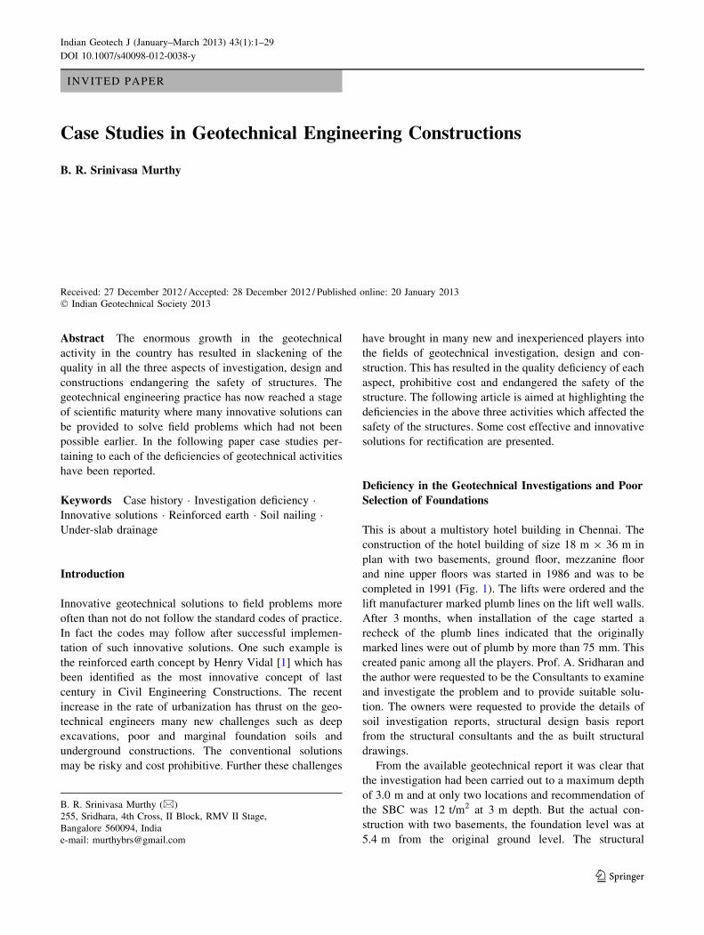
A geo-grid reinforced earth retaining wall for a fly-over
along the National Highway No. 4 was constructed a few
years back. The wall height is varying from 2 to 12 m. At a
location of about 7–8 m height of the wall there was
snapping of connection between facing element and the
geo-grid reinforcement and there was sudden failure of the
RE wall. The failure had taken place over a length of about
10 meters (Figs. 6, 7, and 8).
Analysis and Solution
The soil in the failed zone appeared to be in good condition
as required from an RE wall point of view. In fact the
failure plane had not gone beyond a meter from the wall
face which was the boundary of the drainage zone of
granular material. The soil behind the failed zone was
standing near vertical indicating the sufficiency of the
GL
Sandy-Silt
Marine clay
Water pump
GL
Micropiles 10 m long, 100 mm dia 3 rows @ 250 mm c/c
Fig. 5 Details of remedial
measures
4 Indian Geotech J (January–March 2013) 43(1):1–29
123
reinforcement layers and good quality of compaction. The
failure was essentially in the form of collapse of the panels
due to snapping of the connecting polyester cleats/clamps,
perhaps initially of the upper layers. The number of geo-
grid reinforcement layers provided was found to be rea-
sonable. There was variation in the grade of geo-grid
increasing with depth.
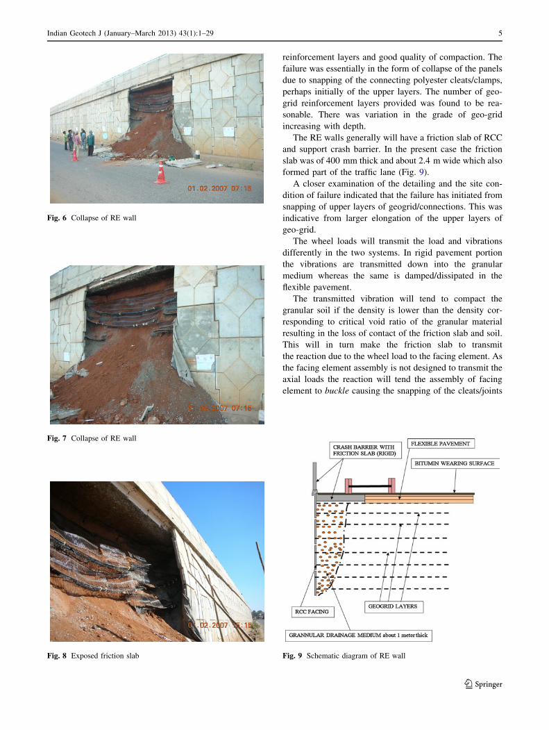
The RE walls generally will have a friction slab of RCC
and support crash barrier. In the present case the friction
slab was of 400 mm thick and about 2.4 m wide which also
formed part of the traffic lane (Fig. 9).
A closer examination of the detailing and the site con-
dition of failure indicated that the failure has initiated from
snapping of upper layers of geogrid/connections. This was
indicative from larger elongation of the upper layers of
geo-grid.
The wheel loads will transmit the load and vibrations
differently in the two systems. In rigid pavement portion
the vibrations are transmitted down into the granular
medium whereas the same is damped/dissipated in the
flexible pavement.
The transmitted vibration will tend to compact the
granular soil if the density is lower than the density cor-
responding to critical void ratio of the granular material
resulting in the loss of contact of the friction slab and soil.
This will in turn make the friction slab to transmit
the reaction due to the wheel load to the facing element. As
the facing element assembly is not designed to transmit the
axial loads the reaction will tend the assembly of facing
element to buckle causing the snapping of the cleats/joints
Fig. 6 Collapse of RE wall
Fig. 7 Collapse of RE wall
Fig. 8 Exposed friction slab Fig. 9 Schematic diagram of RE wall
Indian Geotech J (January–March 2013) 43(1):1–29 5
123
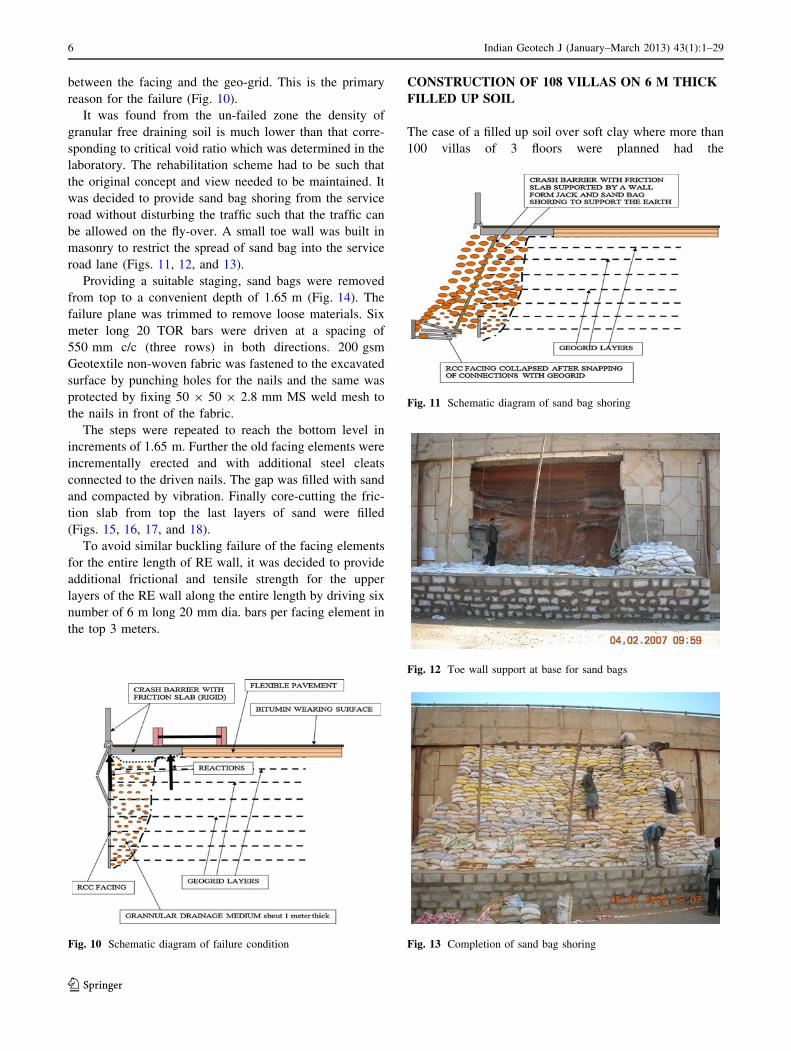
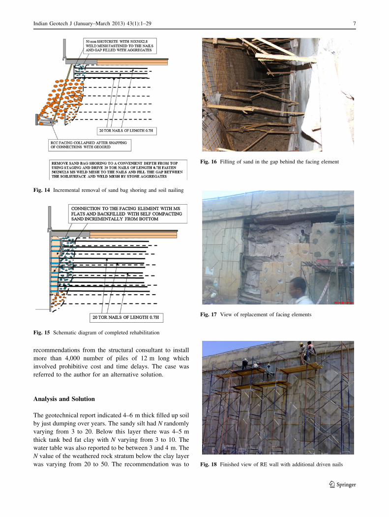
between the facing and the geo-grid. This is the primary
reason for the failure (Fig. 10).
It was found from the un-failed zone the density of
granular free draining soil is much lower than that corre-
sponding to critical void ratio which was determined in the
laboratory. The rehabilitation scheme had to be such that
the original concept and view needed to be maintained. It
was decided to provide sand bag shoring from the service
road without disturbing the traffic such that the traffic can
be allowed on the fly-over. A small toe wall was built in
masonry to restrict the spread of sand bag into the service
road lane (Figs. 11, 12, and 13).
Providing a suitable staging, sand bags were removed
from top to a convenient depth of 1.65 m (Fig. 14). The
failure plane was trimmed to remove loose materials. Six
meter long 20 TOR bars were driven at a spacing of
550 mm c/c (three rows) in both directions. 200 gsm
Geotextile non-woven fabric was fastened to the excavated
surface by punching holes for the nails and the same was
protected by fixing 50 9 50 9 2.8 mm MS weld mesh to
the nails in front of the fabric.
The steps were repeated to reach the bottom level in
increments of 1.65 m. Further the old facing elements were
incrementally erected and with additional steel cleats
connected to the driven nails. The gap was filled with sand
and compacted by vibration. Finally core-cutting the fric-
tion slab from top the last layers of sand were filled
(Figs. 15, 16, 17, and 18).
To avoid similar buckling failure of the facing elements
for the entire length of RE wall, it was decided to provide
additional frictional and tensile strength for the upper
layers of the RE wall along the entire length by driving six
number of 6 m long 20 mm dia. bars per facing element in
the top 3 meters.
CONSTRUCTION OF 108 VILLAS ON 6 M THICK
FILLED UP SOIL
The case of a filled up soil over soft clay where more than
100 villas of 3 floors were planned had the
Fig. 10 Schematic diagram of failure condition
Fig. 11 Schematic diagram of sand bag shoring
Fig. 12 Toe wall support at base for sand bags
Fig. 13 Completion of sand bag shoring
6 Indian Geotech J (January–March 2013) 43(1):1–29
123
recommendations from the structural consultant to install
more than 4,000 number of piles of 12 m long which
involved prohibitive cost and time delays. The case was
referred to the author for an alternative solution.
Analysis and Solution
The geotechnical report indicated 4–6 m thick filled up soil
by just dumping over years. The sandy silt had N randomly
varying from 3 to 20. Below this layer there was 4–5 m
thick tank bed fat clay with N varying from 3 to 10. The
water table was also reported to be between 3 and 4 m. The
N value of the weathered rock stratum below the clay layer
was varying from 20 to 50. The recommendation was to
Fig. 14 Incremental removal of sand bag shoring and soil nailing
Fig. 15 Schematic diagram of completed rehabilitation
Fig. 16 Filling of sand in the gap behind the facing element
Fig. 17 View of replacement of facing elements
Fig. 18 Finished view of RE wall with additional driven nails
Indian Geotech J (January–March 2013) 43(1):1–29 7
123

place the end bearing piles on the weathered rock. The
sandy silt soil had liquid limit of 30–38 % while the
plasticity index was between 12 and 18 %. The clay had
the LL of 48–64 %.
The details of the proposed Villas indicated the foot
prints to be about 160 m2. The total load of the building
was about 650 t indicating a required bearing pressure of
just less than 5 t/m2 for raft slab. The filled up soil could
provide this level of bearing pressure provided the N value
was uniform. The N value was varying quite randomly both
horizontally and vertically across the site. Hence the fol-
lowing scheme which can produce uniform soil parameters
for design was adopted.
1. Assuming the entire footprint of the site as inverted flat
slab with capitol which will be stepped footing for the
columns was proposed in the design.
2. Assuming the width of the footing as the size of the
capitol, the depth of the soil to be treated below the
footing level to obtain the consistent design parameters
was taken as the width of the capitol. The capitol size
was adopted as a maximum of 1.5 m 9 1.5 m.
3. The locally available soil was sampled up to a depth of
2 m and was tested for its compaction characteristics.
It was indicative from laboratory tests the soil in
general has maximum dry density values of more than
1.85 and 2.05 g/cc for standard and modified Proctor’s
energy. Hence it was decided to Proctor density
conditions. The liquid limit of the blended soil was
restricted to be within 30 % and PI within 15 %.
4. On a sample compacted test embankment section,
standard penetration and plate load tests were con-
ducted to evaluate the modulus of sub-grade reaction
for the design of the raft slab. The plate load test
results indicated the modulus of sub-grade reaction
value to be about 1.5 kg/cm3. From N value of more
than 30, the modulus of sub-grade reaction could be
estimated in the same range. In the design, it was
decided to adopt the variation in the value of K. The
variation is made by dividing the entire foundation slab
into strips and the K varied ±20 %, variation of
experimentally obtained K value in the adjoining
strips. Further the slab was divided into strips in the
perpendicular direction and K varied as earlier. The
slab was assumed as 250 mm thick and the capitol
thickness as 400 mm. With this the finite element
analyses were carried out for all the combinations of
loads with variation in the K. The envelope of stress
was obtained for every point and the structural system
was modified to restrict the stresses to be within the
permissible limits. The modified structure was again
analyzed and by iteration the final sections were
obtained.
5. The field implementation started with removing the
soil to a depth of 2 m from the existing level for each
building and stacking the same for blending to get the
desired properties (Fig. 19). Quarry dust was also used
in some cases to reduce the liquid limit. The blended
soil was checked again for the compaction
characteristics.
6. The blended soil was spread in layers of 250 mm and
compacted to modified standard Proctor density using
heavy vibrocompaction equipment (Fig. 20). The field
control was carried out as per standard practice.
Finally SPT and plate load tests were conducted which
indicated the corrected weighted average N value of
more than 15 at 3 m depth below the footing and an
allowable soil pressure of more than 12 t/m2 had been
achieved.
7. The footing was designed as an inverted thickened raft
slab with modulus of subgrade reaction value in the
range of 0.4–0.6 kg/cm3 which resulted in a slab
thickness of less than 200 mm and pedestal of 400 mm
thick. The entire work has been completed (Figs. 21,
22, 23, 24, and 25).
A CASE OF BUILDINGS ON HIGHLY
COMPRESSIBLE ORGANIC PEAT
This is about buildings of 3 floors built for defense per-
sonnel along the west coast. The geotechnical investiga-
tions for the project had been carried out by a well-known
group. There were seven boreholes taken to depths varying
from 5 to 8 m. The soil profile had been identified as dark
sandy soil with N varying from 10 to 25 within the
investigated depths. The general ground level was at about
low tide level. Based on the test results, the geotechnical
Fig. 19 The surface soil stripped to a depth of 2 m
8 Indian Geotech J (January–March 2013) 43(1):1–29
123

investigating agency recommended independent column
foundations at 1.5 m below the existing ground level with
an allowable soil bearing pressure of 12 t/m2. Further it
was recommended to raise the ground formation level to
600 mm above the high tide level which was about
2.5–3.0 m above the local ground level. The plinth level
Fig. 20 Field compaction
Fig. 21 PCC below the raft
Fig. 22 Reinforcement for raft
Fig. 23 Thickened foundation slab
Fig. 24 Typical house under construction
Fig. 25 Interior of the house
Indian Geotech J (January–March 2013) 43(1):1–29 9
123
would be another 450 mm above the formation level. This
necessitated providing two levels of stiff tie beams one at
foundation top and the other at plinth level. The locally
available sandy soil was recommended to be the backfill
material.
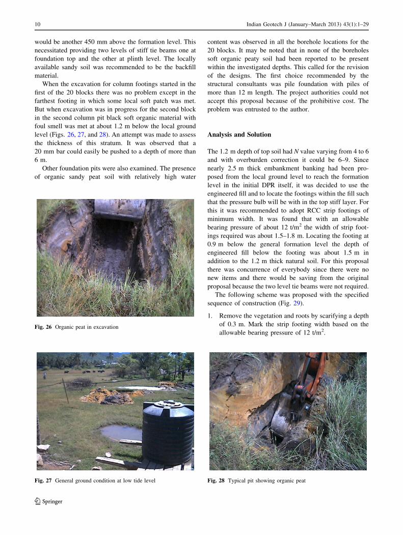
When the excavation for column footings started in the
first of the 20 blocks there was no problem except in the
farthest footing in which some local soft patch was met.
But when excavation was in progress for the second block
in the second column pit black soft organic material with
foul smell was met at about 1.2 m below the local ground
level (Figs. 26, 27, and 28). An attempt was made to assess
the thickness of this stratum. It was observed that a
20 mm bar could easily be pushed to a depth of more than
6 m.
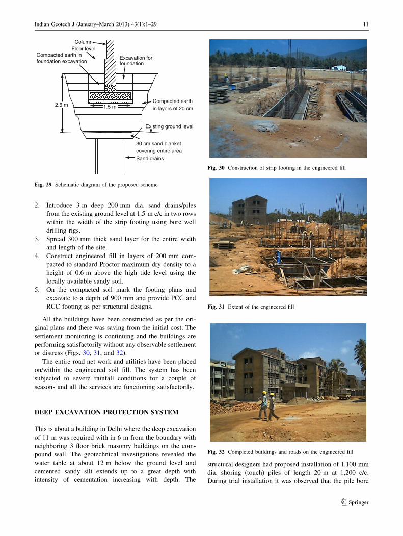
Other foundation pits were also examined. The presence
of organic sandy peat soil with relatively high water
content was observed in all the borehole locations for the
20 blocks. It may be noted that in none of the boreholes
soft organic peaty soil had been reported to be present
within the investigated depths. This called for the revision
of the designs. The first choice recommended by the
structural consultants was pile foundation with piles of
more than 12 m length. The project authorities could not
accept this proposal because of the prohibitive cost. The
problem was entrusted to the author.
Analysis and Solution
The 1.2 m depth of top soil had N value varying from 4 to 6
and with overburden correction it could be 6–9. Since
nearly 2.5 m thick embankment banking had been pro-
posed from the local ground level to reach the formation
level in the initial DPR itself, it was decided to use the
engineered fill and to locate the footings within the fill such
that the pressure bulb will be with in the top stiff layer. For
this it was recommended to adopt RCC strip footings of
minimum width. It was found that with an allowable
bearing pressure of about 12 t/m2 the width of strip foot-
ings required was about 1.5–1.8 m. Locating the footing at
0.9 m below the general formation level the depth of
engineered fill below the footing was about 1.5 m in
addition to the 1.2 m thick natural soil. For this proposal
there was concurrence of everybody since there were no
new items and there would be saving from the original
proposal because the two level tie beams were not required.
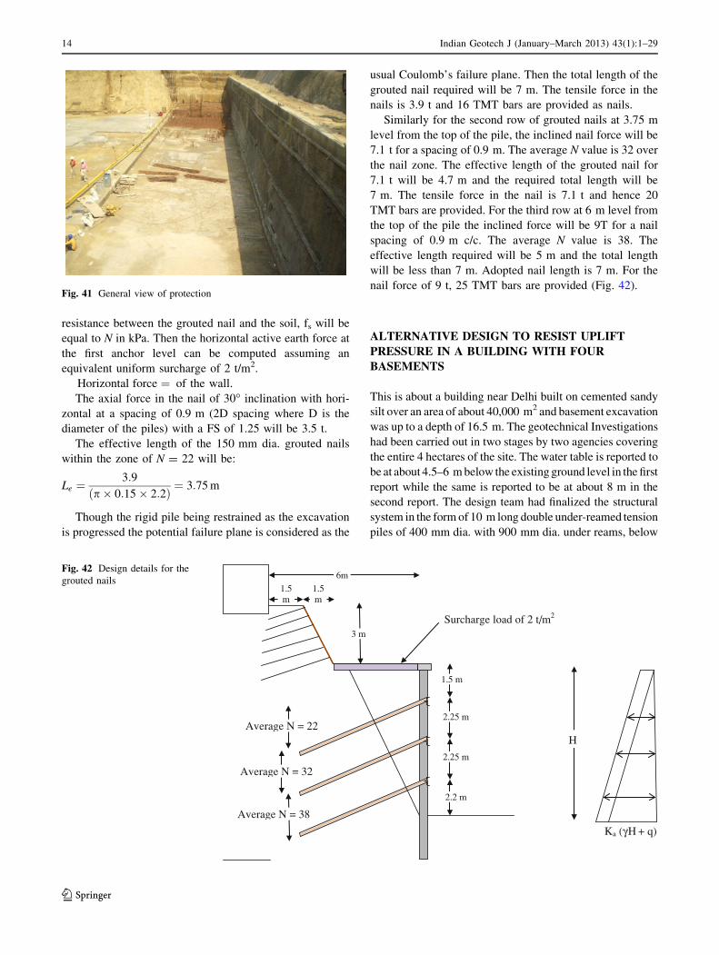
The following scheme was proposed with the specified
sequence of construction (Fig. 29).
1. Remove the vegetation and roots by scarifying a depth
of 0.3 m. Mark the strip footing width based on the
allowable bearing pressure of 12 t/m2.Fig. 26 Organic peat in excavation
Fig. 27 General ground condition at low tide level Fig. 28 Typical pit showing organic peat
10 Indian Geotech J (January–March 2013) 43(1):1–29
123
2. Introduce 3 m deep 200 mm dia. sand drains/piles
from the existing ground level at 1.5 m c/c in two rows
within the width of the strip footing using bore well
drilling rigs.
3. Spread 300 mm thick sand layer for the entire width
and length of the site.
4. Construct engineered fill in layers of 200 mm com-
pacted to standard Proctor maximum dry density to a
height of 0.6 m above the high tide level using the
locally available sandy soil.
5. On the compacted soil mark the footing plans and
excavate to a depth of 900 mm and provide PCC and
RCC footing as per structural designs.
All the buildings have been constructed as per the ori-
ginal plans and there was saving from the initial cost. The
settlement monitoring is continuing and the buildings are
performing satisfactorily without any observable settlement
or distress (Figs. 30, 31, and 32).
The entire road net work and utilities have been placed
on/within the engineered soil fill. The system has been
subjected to severe rainfall conditions for a couple of
seasons and all the services are functioning satisfactorily.
DEEP EXCAVATION PROTECTION SYSTEM
This is about a building in Delhi where the deep excavation
of 11 m was required with in 6 m from the boundary with
neighboring 3 floor brick masonry buildings on the com-
pound wall. The geotechnical investigations revealed the
water table at about 12 m below the ground level and
cemented sandy silt extends up to a great depth with
intensity of cementation increasing with depth. The
structural designers had proposed installation of 1,100 mm
dia. shoring (touch) piles of length 20 m at 1,200 c/c.
During trial installation it was observed that the pile bore
ColumnFloor level
Excavation for foundation
Compacted earth in foundation excavation
Compacted earth in layers of 20 cm
Existing ground level
30 cm sand blanket covering entire areaSand drains
2.5 m 1.5 m
Fig. 29 Schematic diagram of the proposed scheme
Fig. 30 Construction of strip footing in the engineered fill
Fig. 31 Extent of the engineered fill
Fig. 32 Completed buildings and roads on the engineered fill
Indian Geotech J (January–March 2013) 43(1):1–29 11
123

hole was collapsing while crossing the water table level. It
became too cumbersome to install piles and hence for
alternative approach the author was consulted.
Analysis and Solution
The N value varied from 20 to more than 40 at about 12 m
depth. The original proposal of touch piles were supposed
to act as part of the retaining wall. The alternative exca-
vation protection scheme also should be designed to act as
part of the permanent retaining wall. Generally just below
water table very large piles with narrow gap between the
two adjoining piles will have the problem of collapse
especially in sandy silt stratum. Hence the first choice is to
design smaller diameter piles and this can be done by
providing additional props which can do away with large
diameter of cantilevered piles. The deformation of the
excavation protection system should be very minimal to
protect the brick masonry structure on the common com-
pound. The active earth force which will be near constant
irrespective of the size of piles need to be balanced by the
anchor force instead of passive force in the embedment
zone as was originally proposed for 1,100 mm diameter
piles. With these constraints the following scheme was
proposed.
The water table is just below the final excavation level
and it may not be required to provide touch piles. Hence it
was decided to adopt 450 mm dia. piles of 10 m length
spaced at 1,350 mm c/c.
A sloped excavation to a slope of 1(H): 2(V) at a dis-
tance of 1.5 m from the boundary to a depth of 3 m was
made. A 40 mm thick shotcrete layer was provided with
50 9 50 9 2.8 mm MS weld mesh fastened to the exca-
vated sloped surface with U hooks. The 450 mm dia. 10 m
long RCC bored and cast-in situ piles were installed at
-3 m level such that the tips of the piles are at 2 m below
the bottom of excavation. The piles would be just touching
the rear face of the proposed retaining wall. The piles were
connected by a stiff RCC capping beam of size
600 9 450 mm such that the top level of the capping beam
merged with the benching from which the piles were
installed (Figs. 33, 34, and 35).
Now the excavation has to be done incrementally and
the increment is decided by the bending capacity of the
piles. With 6 of 20 TMT reinforcement bars, the moment of
resistance of the pile is 7.5 t-m. For the first row of grouted
nail to be placed at -4.5 m level the horizontal force
required to be mobilized from the grouted nails will be 10 t
for a pile spacing of 1,350 mm. The distance to the
boundary is only 6 m and hence it was required to place the
grouted nails inclined. The inclined component of the force
will be a function of the angle of inclination of the grouted
Fig. 33 Installation of piles
Fig. 34 Piles ready for capping beam
Fig. 35 Capping beam on piles
12 Indian Geotech J (January–March 2013) 43(1):1–29
123

nail itself. Further the interfacial shearing resistance
between the grouted nail and the soil could be computed by
the reported N value. The frictional resistance can be
considered to be equal to N in kPa and by trial and error the
optimal inclination/or spacing could be obtained. The fol-
lowing scheme is successfully implemented (Figs. 36, 37,
38, 39, 40, and 41).
Design Calculations for the Grouted Nails
Because of infrequent use of this technique, design details
of the scheme are provided below.
From N values / can be estimated to be more than 33�and Ka = 0.30. Unit weight of soil is assumed as 1.8 t/m3.
To account for the back slope an equivalent surcharge
pressure of 2.0 t/m2 is estimated. The interfacial frictional
Fig. 36 Building on the compound and excavation up to first
benching
Fig. 37 Installation of grouted nails
Fig. 38 Installation of grouted nails with shotcrete
Fig. 39 Installation of grouted nails with shotcrete in third row
Fig. 40 Protection scheme completed
Indian Geotech J (January–March 2013) 43(1):1–29 13
123
resistance between the grouted nail and the soil, fs will be
equal to N in kPa. Then the horizontal active earth force at
the first anchor level can be computed assuming an
equivalent uniform surcharge of 2 t/m2.
Horizontal force ¼ of the wall.
The axial force in the nail of 30� inclination with hori-
zontal at a spacing of 0.9 m (2D spacing where D is the
diameter of the piles) with a FS of 1.25 will be 3.5 t.
The effective length of the 150 mm dia. grouted nails
within the zone of N = 22 will be:
Le ¼3:9
p� 0:15� 2:2ð Þ ¼ 3:75 m
Though the rigid pile being restrained as the excavation
is progressed the potential failure plane is considered as the
usual Coulomb’s failure plane. Then the total length of the
grouted nail required will be 7 m. The tensile force in the
nails is 3.9 t and 16 TMT bars are provided as nails.
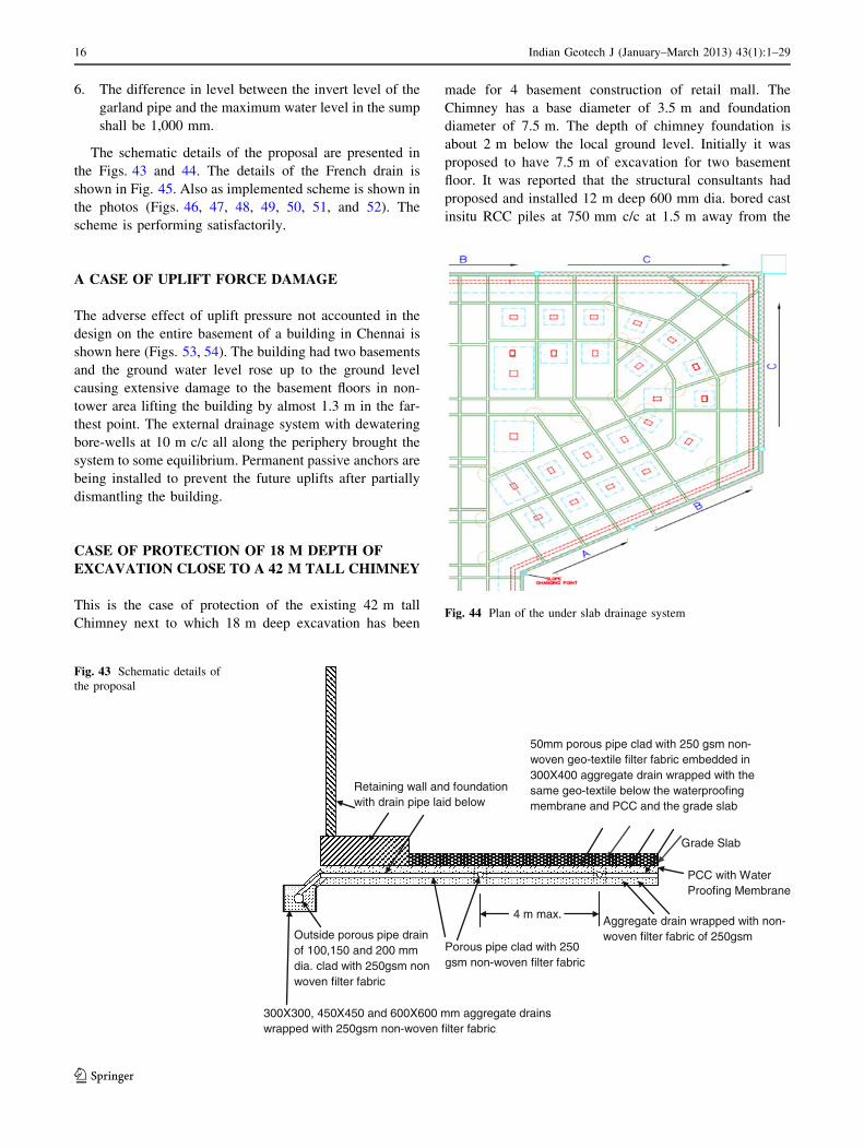
Similarly for the second row of grouted nails at 3.75 m
level from the top of the pile, the inclined nail force will be
7.1 t for a spacing of 0.9 m. The average N value is 32 over
the nail zone. The effective length of the grouted nail for
7.1 t will be 4.7 m and the required total length will be
7 m. The tensile force in the nail is 7.1 t and hence 20
TMT bars are provided. For the third row at 6 m level from
the top of the pile the inclined force will be 9T for a nail
spacing of 0.9 m c/c. The average N value is 38. The
effective length required will be 5 m and the total length
will be less than 7 m. Adopted nail length is 7 m. For the
nail force of 9 t, 25 TMT bars are provided (Fig. 42).
ALTERNATIVE DESIGN TO RESIST UPLIFT
PRESSURE IN A BUILDING WITH FOUR
BASEMENTS
This is about a building near Delhi built on cemented sandy
silt over an area of about 40,000 m2 and basement excavation
was up to a depth of 16.5 m. The geotechnical Investigations
had been carried out in two stages by two agencies covering
the entire 4 hectares of the site. The water table is reported to
be at about 4.5–6 m below the existing ground level in the first
report while the same is reported to be at about 8 m in the
second report. The design team had finalized the structural
system in the form of 10 m long double under-reamed tension
piles of 400 mm dia. with 900 mm dia. under reams, below
Fig. 41 General view of protection
6m
Surcharge load of 2 t/m2
Ka (γH + q)
H
1.5m
1.5m
3 m
1.5 m
2.25 m
2.25 m
2.2 m
Average N = 22
Average N = 32
Average N = 38
Fig. 42 Design details for the
grouted nails
14 Indian Geotech J (January–March 2013) 43(1):1–29
123

the grade slab to take care of the net uplift pressure of about
10 t/m2 due to the possible high water table. The spacing of
the piles was in a grid of 1.5 m 9 1.5 m. The total number of
piles required was in the order of 20,000, the installation of
which from the excavated level of -16.5 m itself was a task.
Further the stability of the bore hole to accommodate 900 mm
dia. 2 reams below water table was causing delay in the
implementation of the project. The author was requested to
examine the possibility of providing the under slab drainage
system as an alternative to relieve the uplift pressures in-lieu
of the structural system with under-reamed piles.
Extensive discussions were made with all concerned
about the design basis and the effectiveness of the system
to clear the apprehensions of all concerned. The Architects
and the Structural Consultants were specific that the under
slab drainage system should take care of all the exigencies.
Hence the following designs have been made little more
conservatively which can effectively function with 100 %
efficiency without compromising the factor of safety.
The design inputs required for the under slab uplift
relieving system are assumed/arrived as follows.
1. The depth to the foundation level below the water
table: Since it is reported to be variable with season as
a conservative measure the water table level has been
assumed to be at 1.5 m from the ground level. The
corresponding water head acting below the grade slab
will be 15 meters.
2. The coefficient of permeability of the soil: The geo-
technical reports have not indicated the permeability
values. Since the grain size distribution values have been
given for all the layers attempt was made to obtain the
coefficient of permeability values based on Hazen’s
equation. This was also compared with the presumptive
values reported in literature for specific idealized soil
groups of this range. Again conservative values have
been selected for the designs. The coefficient of
permeability values have been chosen in the range of
10-3–10-5 cm/s. Also field permeability tests were
requested by fresh tests and the values obtained were in
between the range assumed.
3. Design Philosophy:
a) The design philosophy adopted is to provide a
drainage system to dissipate the hydro-static
pressure head. There will be two levels of
drainage system. First the under slab drainage
system which are laid below the raft/grade slab
between the column footings. The drains are
essentially French drains with drain pipe clad with
non-woven geo-textile filter cloth embedded in an
aggregate drain of size 3d 9 3d which is wrapped
with filter cloth. The second level is garland drains
which are again French drains with larger size to
take care of the increased discharge with distance
located at a depth below the under slab drains to
provide the necessary driving head. The under slab
drains are connected to the garland drain below
the retaining wall foundation.
b) The peripheral garland drain will be linked to
sumps located at a depth below the garland drains
with a required driving head.
c) The water from the sump will be pumped using
submersible pumps with auto-levelcontrollers.
d) The pumps should be designed to pump out the
water collected over 1 h in 20 min.
Design Outputs are obtained as follows.
1. The garland drain behind the retaining wall will have
several segments with sump wells pumps. The top-
phreatic line generates and equilibrates with time as
the water from the sumps is pumped. The parabolic
shape of the top phreatic line is controlled by the
equation R0 = 3,000 H (k)0.5 where k is in m/s.
2. The yield per running meter of the pipe will be q ¼ kH2
2R0
with compatible units. The yield per running meter of
the wall will be about 1,000 l/day. For 25 meters it will
be 25,000 l/day. Pipe drain of 100 mm wrapped with
250 gsm non-woven filter fabric embedded in an
aggregate drain of 300 9 300 mm again wrapped with
filter fabric of 250 gsm is proposed with a driving head
of 1 m. For every subsequent 25 m the size of the pipe
has been changed to 150 mm with aggregate drain of
450 9 450 mm and 200 mm with aggregate drain of
600 9 600 mm. At this point after draining a distance
of 75 m a sump well with pumping system is provided.
The sump also gets the discharge over a distance of
75 m from the pipe on the other direction.
3. The capacity of the sump well shall be to store 20 min
of water draining into the sumps from a distance of
75 m each from both the directions. This requires a
size of about 2,500 lit of live storage which should be
pumped in about 7–8 min. For this the pump capacity
required to pump over a head of about 25 m is about
2.5 HP. A standby pumping system with differential
level of auto-controllers will be required to take care of
malfunctioning of the pump if any.
4. The under slab drain net work will have a grid of
50 mm porous/slotted pipes wrapped with 250 gsm
non-woven filter cloth and embedded in an aggregate
drain of 300 9 400 mm again wrapped with 250 gsm
filter fabric. The spacing in both the directions will be
4 m c/c maximum.
5. The under slab drains get connected suitably to the
garland pipe net work. The difference in level between
the under slab pipe drain invert level and the garland
pipe drain invert level shall be 500 mm minimum.
Indian Geotech J (January–March 2013) 43(1):1–29 15
123
6. The difference in level between the invert level of the
garland pipe and the maximum water level in the sump
shall be 1,000 mm.
The schematic details of the proposal are presented in
the Figs. 43 and 44. The details of the French drain is
shown in Fig. 45. Also as implemented scheme is shown in
the photos (Figs. 46, 47, 48, 49, 50, 51, and 52). The
scheme is performing satisfactorily.
A CASE OF UPLIFT FORCE DAMAGE
The adverse effect of uplift pressure not accounted in the
design on the entire basement of a building in Chennai is
shown here (Figs. 53, 54). The building had two basements
and the ground water level rose up to the ground level
causing extensive damage to the basement floors in non-
tower area lifting the building by almost 1.3 m in the far-
thest point. The external drainage system with dewatering
bore-wells at 10 m c/c all along the periphery brought the
system to some equilibrium. Permanent passive anchors are
being installed to prevent the future uplifts after partially
dismantling the building.
CASE OF PROTECTION OF 18 M DEPTH OF
EXCAVATION CLOSE TO A 42 M TALL CHIMNEY
This is the case of protection of the existing 42 m tall
Chimney next to which 18 m deep excavation has been
made for 4 basement construction of retail mall. The
Chimney has a base diameter of 3.5 m and foundation
diameter of 7.5 m. The depth of chimney foundation is
about 2 m below the local ground level. Initially it was
proposed to have 7.5 m of excavation for two basement
floor. It was reported that the structural consultants had
proposed and installed 12 m deep 600 mm dia. bored cast
insitu RCC piles at 750 mm c/c at 1.5 m away from the
4 m max.
Retaining wall and foundation with drain pipe laid below
50mm porous pipe clad with 250 gsm non-woven geo-textile filter fabric embedded in 300X400 aggregate drain wrapped with the same geo-textile below the waterproofing membrane and PCC and the grade slab
Grade Slab
PCC with Water Proofing Membrane
Aggregate drain wrapped with non-woven filter fabric of 250gsm
Porous pipe clad with 250 gsm non-woven filter fabric
Outside porous pipe drain of 100,150 and 200 mm dia. clad with 250gsm non woven filter fabric
300X300, 450X450 and 600X600 mm aggregate drains wrapped with 250gsm non-woven filter fabric
Fig. 43 Schematic details of
the proposal
Fig. 44 Plan of the under slab drainage system
16 Indian Geotech J (January–March 2013) 43(1):1–29
123

chimney foundation to protect the excavation which was to
be at about 6 m away from the chimney footing edge.
Since the present excavation is much deeper than the ori-
ginal depth it was necessary to protect the Chimney and the
excavation. The following scheme involving soil nailing,
micro-piling and grouted nails were in combination pro-
posed (Fig. 55).
Step 1 Leaving sufficient working space behind the
proposed retaining wall install 20 m long 200 mm dia.
MS pipes of 6 mm thick as micro-piles in predrilled
holes of 300 mm dia. drilled using the bore-well drilling
rigs (Figs. 56, 57). Grout the annulus space with cement
slurry with water cement ratio of 0.42 adding non-shrink
grout compound. Fill the pipe with M20 concrete. Weld
a capping beam of ISMC200 connecting all the piles.
Step 2 Excavate a depth of 2 m and drive 8 m long
20TOR bars at 100 with horizontal as nails @ 400 mm
c/c in the space between the micropiles (Fig. 58). Weld
Fig. 45 Typical French drain
Fig. 46 View of the under slab drains
Fig. 47 View of the under slab drains
Fig. 48 Slotted pipes covered with geotextile
Fig. 49 Under slab drainage junction
Indian Geotech J (January–March 2013) 43(1):1–29 17
123
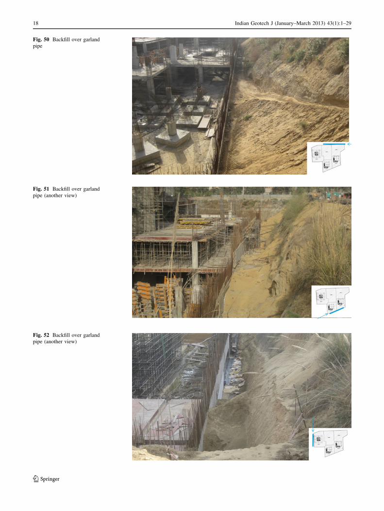
Fig. 50 Backfill over garland
pipe
Fig. 51 Backfill over garland
pipe (another view)
Fig. 52 Backfill over garland
pipe (another view)
18 Indian Geotech J (January–March 2013) 43(1):1–29
123

75 9 75 9 4.2 mm MS weld mesh to the pipe surface
and to the nails with cross bars and provide 50 mm thick
shotcrete as per IS:9012.
Step 3 Repeat the step 2 three more times to reach -8 m
level.
Step 4 Weld 2 9 100 ISMC wailer beam to the face of
the micro pile at -9 m level. Drill at the center of the
space between the micro-piles 150 mm dia. 15 m long
bore holes inclined at 30� at 800 mm c/c and place
25TMT bars with spacers and grout with pure cement
slurry with water cement ratio of 0.42 and adding non-
shrink grout compound under a pressure of 1.5 bar.
Fasten 75 9 75 9 4.2 mm MS weld mesh with U hooks
to the soil surface and by welding to the wailer beam and
micro-piles and provide 50 mm thick shotcrete.
Step 5 After the grout is set (minimum 3 days) excavate
further 2 m and repeat the step 4 twice with nails
inclined at 15� to reach -14 m with grouted nails wailer
beams at -11 m and -13 m levels.
Step 6 Repeat step 5 twice with 32TMT bars with
grouted nails and wailer beams at -15 and -17 m
levels. Complete the excavation to the required level and
construct the retaining wall as per structural designs with
no earth pressure on the walls since the grouted nails
together with micro-piles and wailer beams are taking
care of the earth pressure. Water proofing could be done
on the shotcrete surface (Figs. 59, 60, and 61).
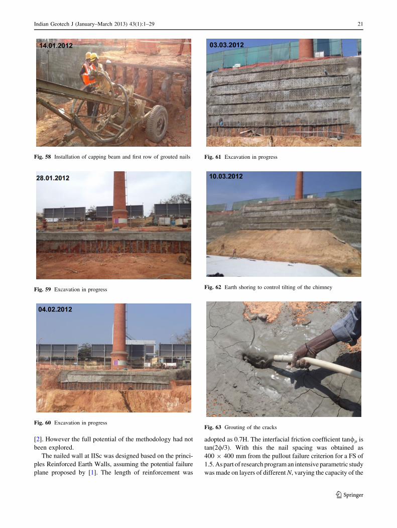
The work was progressing satisfactorily and grouted
nails were being installed at third level when the civil
contractor wanted to hasten the raft and wall construction
requested the excavation and protection work contractor to
complete the work in 3 days the remaining three rows. This
made the excavation protection contractor to install every
day one row of nails without allowing the grout to set and
stabilize the system. The unstabilized 6 m depth of exca-
vation in the bottom caused the cracks to appear on the
surface very close to the previously installed RCC piles. At
the time of appearance of the crack, work on last row of
grouted nails had just started. Using total station the ver-
ticality of the Chimney which was being monitored from
the beginning indicated that the Chimney has tilted by
more than 85 mm in just 2 h. Immediately earth and rock
boulder shoring was provided before deciding further
action (Fig. 62).
A detailed investigation revealed that the earlier instal-
led piles had not been provided with capping beams. The
piles had become floating system. Also it was possible that
while installing the grouted nails at -11 m level the angle
of the grouted nail not being properly maintained might
have hit the bottom tip of the RCC pile. It was indicative
from the bulging at -13 m level that the unset grouted
nails had not offered any resistance. The cracks had
developed to quite large depths of more than a meter.
Immediately cement slurry grout with non-shrink grout
compound was pumped into the cracks. The amount of
grout consumed was quite extensive and it was more than
100 bags of cement and it was not possible to ascertain
where all it has gone (Fig. 63).
The RCC piles were interconnected at ground level
with ISMB encased in concrete as capping beam
(Figs. 64, 65). Further the structural shoring in the form of
struts was provided from the all ready cast raft and
foundations at a distance more than 12 m from the micro
piles to the wailer beam at -11 m level (Figs. 66, 67, and
68). With this earth shoring, grouting at the top, structural
shoring and strutting, it was observed from the total sta-
tion survey that the movement of the top of the Chimney
Fig. 53 Uplifted basement
Fig. 54 Crushing of the column due to uplift
Indian Geotech J (January–March 2013) 43(1):1–29 19
123

had stopped. By this time the total deflection of the top of
the Chimney had crossed 135 mm. It was further advised
to incrementally remove the earth shoring and introduce
the remaining grouted nails and wailer beams along with
the required grouted nails to reach the bottom of the
excavation.
CASES OF EXCAVATION PROTECTION WITH
DRIVEN AND GROUTED NAILS
A number of projects (more than 200) have been suc-
cessfully implemented throughout the country and a few of
them are discussed.
Design of Nailed Wall
This is about the construction of driven nailed walls at
Indian Institute of Science Campus, Bangalore. While
constructing an underpass across the National Highway in
front of IISc, by box-jacking technique, the approach
ramps were initially designed to be of RCC walls. For this
about 16 well grown trees have to be cut for which IISc had
granted permission. Just at that time in another project the
author had developed a method of driving the nails using
compressor driven percussion Jack-Hammer. Earlier the
driven nails used to be installed using conventional sludge
hammer, which was not practicable for large size projects
Fig. 55 Schematic diagram of
the design
Fig. 56 Installation of micro piles
Fig. 57 Installation of capping beam and first row of grouted nails
20 Indian Geotech J (January–March 2013) 43(1):1–29
123
[2]. However the full potential of the methodology had not
been explored.
The nailed wall at IISc was designed based on the princi-
ples Reinforced Earth Walls, assuming the potential failure
plane proposed by [1]. The length of reinforcement was
adopted as 0.7H. The interfacial friction coefficient tan/l is
tan(2//3). With this the nail spacing was obtained as
400 9 400 mm from the pullout failure criterion for a FS of
1.5. As part of research program an intensive parametric study
was made on layers of different N, varying the capacity of the
Fig. 58 Installation of capping beam and first row of grouted nails
Fig. 59 Excavation in progress
Fig. 60 Excavation in progress
Fig. 61 Excavation in progress
Fig. 62 Earth shoring to control tilting of the chimney
Fig. 63 Grouting of the cracks
Indian Geotech J (January–March 2013) 43(1):1–29 21
123

compressor which runs the Jack-Hammer and conducting
pull out tests on the driven nails. The N varied from 15 to 40
for different layers over a depth of 6 m. The compressor
capacity was varied and the adopted capacities were about
165, 200 and 330 cfm with delivery pressure rating of
4.5–6 kgf/cm2. Then a correlation was attempted to link the
N value with rate of driving the bars with a given compressor
capacity which directly measures the penetration strength of
the ground. By adopting the correlation between N and / the
spacing was linked to the rate of driving with a given capacity
of the compressor.
It was found that the rate of penetration of 20 TOR bar of
length less than 6 m with a standard compressor of capacity
165 cfm can be directly linked with N as N = 0.8 R0 where R0
is the time in seconds for penetration of 1 m. Similarly cor-
relations have been generated for other sizes of the nail and
compressor capacities. Further the N value has been corre-
lated directly with interfacial shear strength, ss by many
people for piles and anchors. It is related as ss = N to
2 N where N is in kPa for small and large displacements
respectively. Adopting this relationship of ss = N, the spac-
ing has been directly linked with rate of penetration. From the
study it was clear that the spacing can be related to N and
hence to R0 as Sx = Sy = 1.25 N = R0. The correlation is not
valid for N [ 50 since in the test site all the N values were less
than 50 (Figs. 69, 70, 71, 72, 73, 74, and 75).
In Chennai where soft clay and sandy soil layers were
alternating, for an excavation of 7.5 m deep next to the
Fig. 64 Capping beam on the RCC piles
Fig. 65 Capping beam on the RCC piles
Fig. 66 Structural shoring
Fig. 67 Removal of earth shoring and building of RCC wall with
structural shoring in position
Fig. 68 Removal of earth shoring and building of RCC wall with
structural shoring in position
22 Indian Geotech J (January–March 2013) 43(1):1–29
123

existing building the nails were introduced in both upward
and downward inclination from the clay layers to penetrate
into the sandy layer to provide better fictional resistance
(Figs. 76, 77).
Fig. 69 Driven nails for the ramp side walls at IISc
Fig. 70 Driven nails for the ramp side walls at IISc
Fig. 71 Concreting of the facing element at IISc
Fig. 72 Finished ramp side walls for the underpass at IISc
Fig. 73 Protection of deep excavation at Air force station by driven
nails
Fig. 74 Protection of deep excavation at Air force station by driven
nails
Indian Geotech J (January–March 2013) 43(1):1–29 23
123
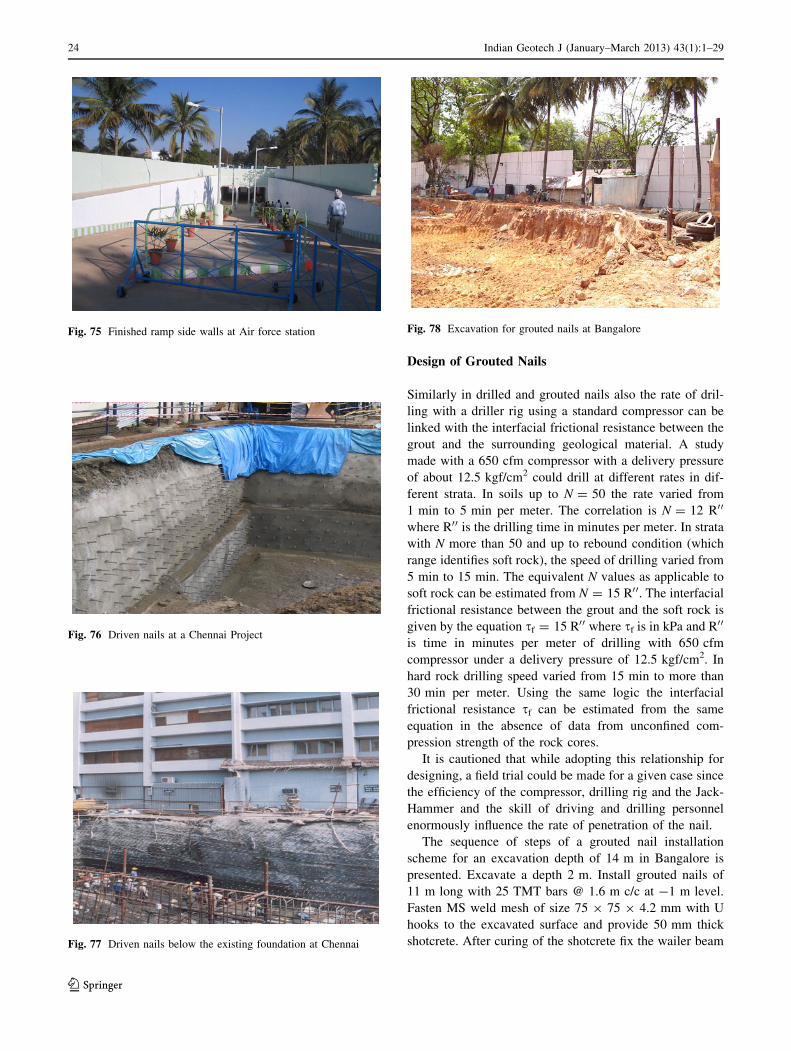
Design of Grouted Nails
Similarly in drilled and grouted nails also the rate of dril-
ling with a driller rig using a standard compressor can be
linked with the interfacial frictional resistance between the
grout and the surrounding geological material. A study
made with a 650 cfm compressor with a delivery pressure
of about 12.5 kgf/cm2 could drill at different rates in dif-
ferent strata. In soils up to N = 50 the rate varied from
1 min to 5 min per meter. The correlation is N = 12 R00
where R00 is the drilling time in minutes per meter. In strata
with N more than 50 and up to rebound condition (which
range identifies soft rock), the speed of drilling varied from
5 min to 15 min. The equivalent N values as applicable to
soft rock can be estimated from N = 15 R00. The interfacial
frictional resistance between the grout and the soft rock is
given by the equation sf = 15 R00 where sf is in kPa and R00
is time in minutes per meter of drilling with 650 cfm
compressor under a delivery pressure of 12.5 kgf/cm2. In
hard rock drilling speed varied from 15 min to more than
30 min per meter. Using the same logic the interfacial
frictional resistance sf can be estimated from the same
equation in the absence of data from unconfined com-
pression strength of the rock cores.
It is cautioned that while adopting this relationship for
designing, a field trial could be made for a given case since
the efficiency of the compressor, drilling rig and the Jack-
Hammer and the skill of driving and drilling personnel
enormously influence the rate of penetration of the nail.
The sequence of steps of a grouted nail installation
scheme for an excavation depth of 14 m in Bangalore is
presented. Excavate a depth 2 m. Install grouted nails of
11 m long with 25 TMT bars @ 1.6 m c/c at -1 m level.
Fasten MS weld mesh of size 75 9 75 9 4.2 mm with U
hooks to the excavated surface and provide 50 mm thick
shotcrete. After curing of the shotcrete fix the wailer beam
Fig. 75 Finished ramp side walls at Air force station
Fig. 76 Driven nails at a Chennai Project
Fig. 77 Driven nails below the existing foundation at Chennai
Fig. 78 Excavation for grouted nails at Bangalore
24 Indian Geotech J (January–March 2013) 43(1):1–29
123

to the nails by welding. Fill the gap between the shotcrete
surface and wailer beam with concrete to achieve effective
contact between wailer beam and the shotcrete surface.
Fig. 79 Excavation and two rows of grouted nails
Fig. 80 Shotcreted surface after two rows of grouted nails
Fig. 81 Deep excavation and grouted nails as finished
Fig. 82 Slope protection at NMDC project -Combination of driven
and grouted nails
Fig. 83 Deep excavation with driven and grouted nails as finished
Fig. 84 Deep excavation with driven and grouted nails as finished
Indian Geotech J (January–March 2013) 43(1):1–29 25
123
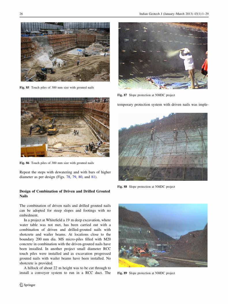
Repeat the steps with dewatering and with bars of higher
diameter as per design (Figs. 78, 79, 80, and 81).
Design of Combination of Driven and Drilled Grouted
Nails
The combination of driven nails and drilled grouted nails
can be adopted for steep slopes and footings with no
embedment.
In a project at Whitefield a 19 m deep excavation, where
water table was not met, has been carried out with a
combination of driven and drilled-grouted nails with
shotcrete and wailer beams. At locations close to the
boundary 200 mm dia. MS micro-piles filled with M20
concrete in combination with the driven-grouted nails have
been installed. In another project small diameter RCC
touch piles were installed and as excavation progressed
grouted nails with wailer beams have been installed. No
shotcrete is provided.
A hillock of about 22 m height was to be cut through to
install a conveyor system to run in a RCC duct. The
temporary protection system with driven nails was imple-
Fig. 85 Touch piles of 300 mm size with grouted nails
Fig. 86 Touch piles of 300 mm size with grouted nails
Fig. 87 Slope protection at NMDC project
Fig. 88 Slope protection at NMDC project
Fig. 89 Slope protection at NMDC project
26 Indian Geotech J (January–March 2013) 43(1):1–29
123
mented to facilitate construction of RCC duct. The tem-
porary system was so effective that the authorities decided
to regard the temporary protection as a permanent one and
abandoned the proposed RCC duct (Figs. 82, 83, 84, 85,
86, 87, 88, and 89).
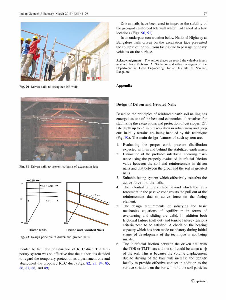
Driven nails have been used to improve the stability of
the geo-grid reinforced RE wall which had failed at a few
locations (Figs. 90, 91).
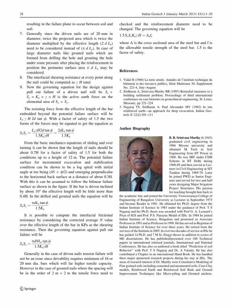
In an underpass construction below National Highway at
Bangalore nails driven on the excavation face prevented
the collapse of the soil from facing due to passage of heavy
vehicles on the surface.
Acknowledgments The author places on record the valuable inputs
received from Professor A. Sridharan and other colleagues in the
Department of Civil Engineering, Indian Institute of Science,
Bangalore.
Appendix
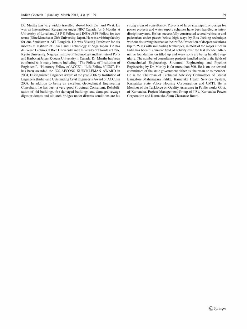
Design of Driven and Grouted Nails
Based on the principles of reinforced earth soil nailing has
emerged as one of the best and economical alternatives for
stabilizing the excavations and protection of cut slopes. Off
late depth up to 25 m of excavation in urban areas and deep
cuts in hilly terrains are being handled by this technique
(Fig. 92). The main design features of such system are.
1. Evaluating the proper earth pressure distribution
expected with-in and behind the stabilized earth mass.
2. Estimation of the probable interfacial shearing resis-
tance using the properly evaluated interfacial friction
value between the soil and reinforcement in driven
nails and that between the grout and the soil in grouted
nails.
3. Suitable facing system which effectively transfers the
active force into the nails.
4. The potential failure surface beyond which the rein-
forcement in the passive zone resists the pull out of the
reinforcement due to active force on the facing
element.
5. The design requirements of satisfying the basic
mechanics equations of equilibrium in terms of
overturning and sliding are valid. In addition both
frictional failure (pull out) and tensile failure (tension)
criteria need to be satisfied. A check on the bearing
capacity which has been made mandatory during initial
stages of development of the technique is not being
insisted.
6. The interfacial friction between the driven nail with
the TOR or TMT bars and the soil could be taken as /of the soil. This is because the volume displacement
due to driving of the bars will increase the density
locally to provide effective contact in addition to the
surface striations on the bar will hold the soil particles
Fig. 90 Driven nails to strengthen RE walls
Fig. 91 Driven nails to prevent collapse of excavation face
Fig. 92 Design principle of driven and grouted nails
Indian Geotech J (January–March 2013) 43(1):1–29 27
123
resulting in the failure plane to occur between soil and
soil.
7. Generally since the driven nails are of 20 mm in
diameter, twice the projected area which is twice the
diameter multiplied by the effective length (2 d Le)
need to be considered instead of (p d Le). In case of
large diameter nails like grouted nails which are
formed from drilling the hole and grouting the hole
under some pressure after placing the reinforcement in
position the perimeter surface area p d Le may be
considered.
8. The interfacial shearing resistance at every point along
the nail could be computed as c H tan/9. Now the governing equation for the design against
pull out failure of a driven nail will be Sx 9
Sy 9 Ka 9 c 9 H is the active earth force on the
elemental area of Sx 9 Sy.
The resisting force from the effective length of the bar
embedded beyond the potential failure surface will be
Le c H 2d tan /. With a factor of safety of 1.5 the two
forms of the forces may be equated to get the equation as
SxSy ¼LecH2d tan /
1:5KacH¼ 2dLe tan /
1:5Ka
From the basic mechanics equations of sliding and over
turning it can be shown that the length of nails should be
about 0.7H for a factor of safety of 1.5 for both the
conditions up to a height of 12 m. The potential failure
surface for incremental excavation and stabilization
condition can be shown to be a log spiral with initial
angle at toe being (45 ? //2) and emerging perpendicular
to the horizontal back surface at a distance of about 0.3H.
With this it can be assumed to follow the bilinear failure
surface as shown in the figure. If the bar is driven inclined
by about 10� the effective length will be little more than
0.4H. In the drilled and grouted nails the equation will be
SxSy ¼pdLe tan /
1:5Ka
It is possible to compute the interfacial frictional
resistance by considering the corrected average N value
over the effective length of the bar in KPa as the shearing
resistance. Then the governing equation against pull out
failure will be
SxSy ¼pdNLe tan /
1:5KacH
Generally in the case of driven nails tension failure will
not be an issue since drivability requires minimum of 16 or
20 mm dia. bars which will far higher tensile capacity.
However in the case of grouted nails where the spacing will
be in the order of 2 m 9 2 m the tensile force need to
checked and the reinforcement diameter need to be
changed. The governing equation will be
1:5 SxSyKac H ¼ Asfs
where A is the cross sectional area of the steel bar and f is
the allowable tensile strength of the steel bar. 1.5 is the
factor of safety.
References
1. Vidal H (1968) La terre armee. Annales de l’institute technique du
batiment et des travauvx publics, Serie Materiaux 30, Supplement
No. 223-4, July–August
2. Sridharan A, Srinivasa Murthy BR (1993) Remedial measures to a
building settlement problem. Proceedings of third international
conference on case histories in geotechnical engineering, St. Louis,
Missouri, pp 221–224
3. Nagaraj TS, Sridharan A, Paul Alexander MV (1982) In situ
reinforced earth—an approach for deep excavation. Indian Geo-
tech Jl 12(2):101–111
Author Biography
B. R. Srinivasa Murthy (b.1943)
graduated civil engineering in
1966 Mysore university and
obtained M Tech in Soil
Engineering from IIT Powai in
1968. He was SRF under CSIR
Scheme in IIT Delhi during
1968-69 and then served as Lec-
turer in Civil Engineering at SIT
Tumkur during 1969-70. Later
he joined PWD as Junior Engi-
neer and served for two and half
years designing Major Irrigation
Project Structures. His passion
for teaching brought him back to
the academic line and joined the University Visweswaraya College of
Engineering of Bangalore University as Lecturer in September 1973
and became Reader in 1981. He obtained his Ph.D. degree from the
Indian Institute of Science in 1983 under the guidance of Prof. T S
Nagaraj and his Ph.D. thesis was awarded with Prof G. A. Leonard’s
Prize of IGS and Prof. P.S. Narayna Medal of IISc. In 1984 he joined
Indian Institute of Science, Bangalore and promoted as Associate
Professor in 1991 and as Professor in 1998. He has served as Registrar of
Indian Institute of Science for over three years. He retired from the
services of the Institute in 2005. In over two decades of service at IISc he
has guided 14 Ph.D. and 7 M Sc (Engg) theses in addition to scores of
ME dissertations. He has published/presented over 100 Technical
papers in international refereed journals, International and National
Conferences. He has also co-authored a book titled ‘‘Prediction of soil
Behavior’’ with Prof. T S Nagaraj and Dr. A Vatsala. He has also
contributed a Chapter in an international Hand Book. He has handled
three major sponsored research projects during his stay at IISc. The
areas of research interest of Dr. Murthy were Constitutive Modeling of
Fine grained soils including cemented and unsaturated soils, Cam-Clay
models, Reinforced Earth and Reinforced Soil Beds and Ground
Improvement Techniques like Micro-piling and Grouted anchors.
28 Indian Geotech J (January–March 2013) 43(1):1–29
123
Dr. Murthy has very widely travelled abroad both East and West. He
was an International Researcher under NRC Canada for 6 Months at
University of Laval and J S P S Fellow and INSA-JSPS Fellow for two
terms (Nine Months) at Gifu University, Japan. He was a visiting faculty
for one Semester at AIT Bangkok. He was Visiting Professor for six
months at Institute of Low Land Technology at Saga Japan. He has
delivered Lectures at Rice University and University of Florida at USA,
Kyoto University, Nagoya Institute of Technology and Institute of Ports
and Harbor at Japan, Queens University in Canada. Dr. Murthy has been
conferred with many honors including ‘‘The Fellow of Institution of
Engineers’’, ‘‘Honorary Fellow of ACCE’’, ‘‘Life Fellow if IGS’’. He
has been awarded the IGS-AFCONS KUECKLEMAN AWARD in
2004, Distinguished Engineer Award of the year 2006 by Institution of
Engineers (India) and Outstanding Civil Engineer’s Award of ACCE in
2008. In addition to being an excellent Geotechnical Engineering
Consultant, he has been a very good Structural Consultant. Rehabili-
tation of old buildings, fire damaged buildings and damaged sewage
digester domes and old arch bridges under distress conditions are his
strong areas of consultancy. Projects of large size pipe line design for
power projects and water supply schemes have been handled as inter-
disciplinary area. He has successfully constructed several vehicular and
pedestrian under passes below high ways by Box-Jacking technique
without disturbing the road or the traffic. Protection of deep excavations
(up to 25 m) with soil nailing techniques, in most of the major cities in
India has been his current field of activity over the last decade. Alter-
native foundations on filled up and week soils are being handled reg-
ularly. The number of consultancy projects handled so far in the fields of
Geotechnical Engineering, Structural Engineering and Pipeline
Engineering by Dr. Murthy is far more than 500. He is on the several
committees of the state government either as chairman or as member.
He is the Chairman of Technical Advisory Committees of Bruhat
Bangalore Mahanagara Palike, Karnataka Health Services System,
Karnataka State Police Housing Corporaration and CMTI. He is
Member of the Taskforce on Quality Assurance in Public works Govt.
of Karnataka, Project Management Group of IISc. Karnataka Power
Corporation and Karnataka Slum Clearance Board.
Indian Geotech J (January–March 2013) 43(1):1–29 29
123