Case Studies in Engineering Failure Analysisiranarze.ir/wp-content/uploads/2016/11/E2743.pdf ·...
9
Case study Failure analysis of tube-to-tubesheet welded joints in a shell-tube heat exchanger Long Liu a , Ning Ding a [1_TD$DIFF] ,b, **, Junbo Shi a , Na Xu a , Weimin Guo a , Chi-Man Lawrence Wu a,b, * a Research Center of Failure Analysis and Engineering Safety Assessment, Shandong Academy of Science, Jinan, PR China b Department of Physics and Materials Science, City University of Hong Kong, Hong Kong, China 1. Introduction Shell-tube heat exchangers are common type of heat exchanger which is widely used in industries such as oil refineries, thermoelectricity and mineral processing [1]. This type of heat exchanger consists of a shell (usually a large pressure vessel) with a bundle of tubes inside it. Heat is transferred between the fluid inside the tube (the tube side) and the fluid outside the tube but inside the shell (the shell side) through the tube walls, either from tube side to shell side or vice versa. A combination of welding and expansion process was usually the main technique for connecting the tube ends with the tubesheet in such type of heat exchangers. As we know, welded joints are very susceptible to sustain residual stresses. Due to the mechanisms such as stress corrosion, pitting corrosion, welding defects and so on, cracks and damages may easily formed at the tube-to-tubesheet welded joints [1,2]. Thus, tube-to-tubesheet welded joints become a weak part in such heat exchangers [3]. During the last several decades, a number of failures of the tube-to-tubesheet welded joint in the shell-tube heat exchangers were investigated [4–9]. However, failures of such welded joints are far from being eradicated completely and need to be further considered. Case Studies in Engineering Failure Analysis 7 (2016) 32–40 ARTICLE INFO Article history: Received 6 June 2016 Received in revised form 17 June 2016 Accepted 17 June 2016 Available online 24 June 2016 Keywords: Welded joint Failure analysis Fatigue Fracture Shell-tube heat exchanger ABSTRACT Failure analysis was carried out on a tube-to-tubesheet welded joint of a shell-tube heat exchanger to confirm its failure mechanism. The collected evidence suggests that [11_TD$DIFF]the failure of the tube-to-tubesheet welded joint was induced by fatigue. Under the morphology analysis, the fracture surface exhibit obvious fatigue crack propagation traces. Fatigue striations were observed clearly in the propagation zone. Detecting results showed that chemical composition and mechanical properties of the tubes was consistent with the standard requirements for the 304 stainless steel. The metallographic test showed that the microstructure of both the tube and tubesheet were normal. However, serious defects were found at the tube-to-tubesheet welded joint. The fatigue crack initiated from the defects at the tube-to-tubesheet welded joint. The periodic load might come from the resonant vibration of the tube or the changes in temperature and pressure of the fluid inside the heat exchanger. Bad welding and unsuitable expansion position of the tubes at the tube-to-tubesheet might give rise to the formation of initial cracks. ß 2016 The Authors. Published by Elsevier Ltd. This is an open access article under the CC BY-NC-ND license (http://creativecommons.org/licenses/by-nc-nd/4.0/). * Corresponding author at: Department of Physics and Materials Science, City University of Hong Kong, Hong Kong, China. E-mail address: [email protected] (N. Ding). ** Corresponding author at: Shandong Academy of Sciences, Jinan, PR China. E-mail address: [email protected] (C.-M. Wu). Contents lists available at ScienceDirect Case Studies in Engineering Failure Analysis journal homepage: www.elsevier.com/locate/csefa http://dx.doi.org/10.1016/j.csefa.2016.06.002 2213-2902/ß 2016 The Authors. Published by Elsevier Ltd. This is an open access article under the CC BY-NC-ND license (http://creativecommons.org/ licenses/by-nc-nd/4.0/).
Transcript of Case Studies in Engineering Failure Analysisiranarze.ir/wp-content/uploads/2016/11/E2743.pdf ·...
Case Studies in Engineering Failure Analysis 7 (2016) 32–40
Contents lists available at ScienceDirect
Case Studies in Engineering Failure Analysis
journal homepage: www.e lsev ier .com/ locate /csefa
Case study
Failure analysis of tube-to-tubesheet welded joints in
a shell-tube heat exchangerLong Liu a, Ning Ding a[1_TD$DIFF]
,b,**, Junbo Shi a, Na Xu a, Weimin Guo a,Chi-Man Lawrence Wu a,b,*a Research Center of Failure Analysis and Engineering Safety Assessment, Shandong Academy of Science, Jinan, PR Chinab Department of Physics and Materials Science, City University of Hong Kong, Hong Kong, China
A R T I C L E I N F O
Article history:
Received 6 June 2016
Received in revised form 17 June 2016
Accepted 17 June 2016
Available online 24 June 2016
Keywords:
Welded joint
Failure analysis
Fatigue
Fracture
Shell-tube heat exchanger
A B S T R A C T
Failure analysis was carried out on a tube-to-tubesheet welded joint of a shell-tube heat
exchanger to confirm its failure mechanism. The collected evidence suggests that [11_TD$DIFF]the
failure of the tube-to-tubesheet welded joint was induced by fatigue. Under the
morphology analysis, the fracture surface exhibit obvious fatigue crack propagation traces.
Fatigue striations were observed clearly in the propagation zone. Detecting results showed
that chemical composition and mechanical properties of the tubes was consistent with the
standard requirements for the 304 stainless steel. The metallographic test showed that the
microstructure of both the tube and tubesheet were normal. However, serious defects
were found at the tube-to-tubesheet welded joint. The fatigue crack initiated from the
defects at the tube-to-tubesheet welded joint. The periodic load might come from the
resonant vibration of the tube or the changes in temperature and pressure of the fluid
inside the heat exchanger. Bad welding and unsuitable expansion position of the tubes at
the tube-to-tubesheet might give rise to the formation of initial cracks.
� 2016 The Authors. Published by Elsevier Ltd. This is an open access article under the CC
BY-NC-ND license (http://creativecommons.org/licenses/by-nc-nd/4.0/).
1. Introduction
Shell-tube heat exchangers are common type of heat exchanger which is widely used in industries such as oil refineries,thermoelectricity and mineral processing [1]. This type of heat exchanger consists of a shell (usually a large pressure vessel)with a bundle of tubes inside it. Heat is transferred between the fluid inside the tube (the tube side) and the fluid outside thetube but inside the shell (the shell side) through the tube walls, either from tube side to shell side or vice versa. Acombination of welding and expansion process was usually the main technique for connecting the tube ends with thetubesheet in such type of heat exchangers. As we know, welded joints are very susceptible to sustain residual stresses. Due tothe mechanisms such as stress corrosion, pitting corrosion, welding defects and so on, cracks and damages may easilyformed at the tube-to-tubesheet welded joints [1,2]. Thus, tube-to-tubesheet welded joints become a weak part in such heatexchangers [3]. During the last several decades, a number of failures of the tube-to-tubesheet welded joint in the shell-tubeheat exchangers were investigated [4–9]. However, failures of such welded joints are far from being eradicated completelyand need to be further considered.
* Corresponding author at: Department of Physics and Materials Science, City University of Hong Kong, Hong Kong, China.
E-mail address: [email protected] (N. Ding).
** Corresponding author at: Shandong Academy of Sciences, Jinan, PR China.
E-mail address: [email protected] (C.-M. Wu).
http://dx.doi.org/10.1016/j.csefa.2016.06.002
2213-2902/� 2016 The Authors. Published by Elsevier Ltd. This is an open access article under the CC BY-NC-ND license (http://creativecommons.org/
licenses/by-nc-nd/4.0/).
L. Liu et al. / Case Studies in Engineering Failure Analysis 7 (2016) 32–40 33
In this work, fracture failure of a shell-tube heat exchanger at the tube-to-tubesheet welded joints was investigated usingvarious material analysis techniques. Fatigue started at initial defects of the welded joint was confirmed as the failuremechanism of the heat exchanger.
2. Background
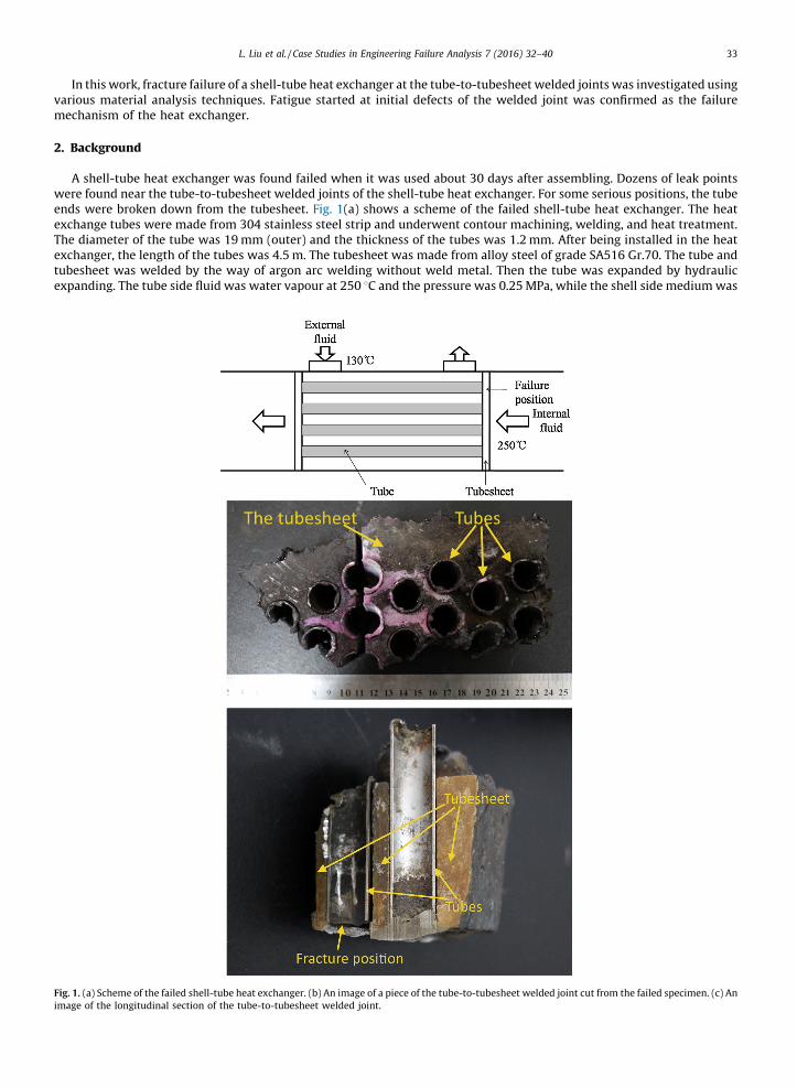
A shell-tube heat exchanger was found failed when it was used about 30 days after assembling. Dozens of leak pointswere found near the tube-to-tubesheet welded joints of the shell-tube heat exchanger. For some serious positions, the tubeends were broken down from the tubesheet. Fig. 1(a) shows a scheme of the failed shell-tube heat exchanger. The heatexchange tubes were made from 304 stainless steel strip and underwent contour machining, welding, and heat treatment.The diameter of the tube was 19 mm (outer) and the thickness of the tubes was 1.2 mm. After being installed in the heatexchanger, the length of the tubes was 4.5 m. The tubesheet was made from alloy steel of grade SA516 Gr.70. The tube andtubesheet was welded by the way of argon arc welding without weld metal. Then the tube was expanded by hydraulicexpanding. The tube side fluid was water vapour at 250 8C and the pressure was 0.25 MPa, while the shell side medium was
[(Fig._1)TD$FIG]Fig. 1. (a) Scheme of the failed shell-tube heat exchanger. (b) An image of a piece of the tube-to-tubesheet welded joint cut from the failed specimen. (c) An
image of the longitudinal section of the tube-to-tubesheet welded joint.
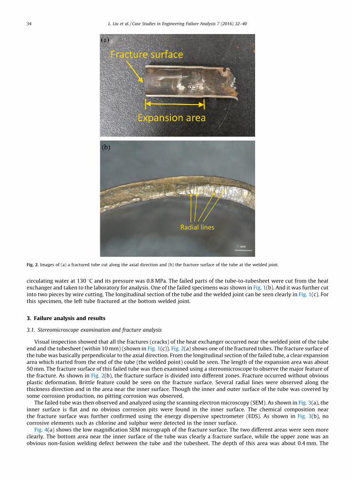
[(Fig._2)TD$FIG]
Fig. 2. Images of (a) a fractured tube cut along the axial direction and (b) the fracture surface of the tube at the welded joint.
L. Liu et al. / Case Studies in Engineering Failure Analysis 7 (2016) 32–4034
circulating water at 130 8C and its pressure was 0.8 MPa. The failed parts of the tube-to-tubesheet were cut from the heatexchanger and taken to the laboratory for analysis. One of the failed specimens was shown in Fig. 1(b). And it was further cutinto two pieces by wire cutting. The longitudinal section of the tube and the welded joint can be seen clearly in Fig. 1(c). Forthis specimen, the left tube fractured at the bottom welded joint.
3. Failure analysis and results
3.1. Stereomicroscope examination and fracture analysis
Visual inspection showed that all the fractures (cracks) of the heat exchanger occurred near the welded joint of the tubeend and the tubesheet (within 10 mm) (shown in Fig. 1(c)). Fig. 2(a) shows one of the fractured tubes. The fracture surface ofthe tube was basically perpendicular to the axial direction. From the longitudinal section of the failed tube, a clear expansionarea which started from the end of the tube (the welded point) could be seen. The length of the expansion area was about50 mm. The fracture surface of this failed tube was then examined using a stereomicroscope to observe the major feature ofthe fracture. As shown in Fig. 2(b), the fracture surface is divided into different zones. Fracture occurred without obviousplastic deformation. Brittle feature could be seen on the fracture surface. Several radial lines were observed along thethickness direction and in the area near the inner surface. Though the inner and outer surface of the tube was covered bysome corrosion production, no pitting corrosion was observed.
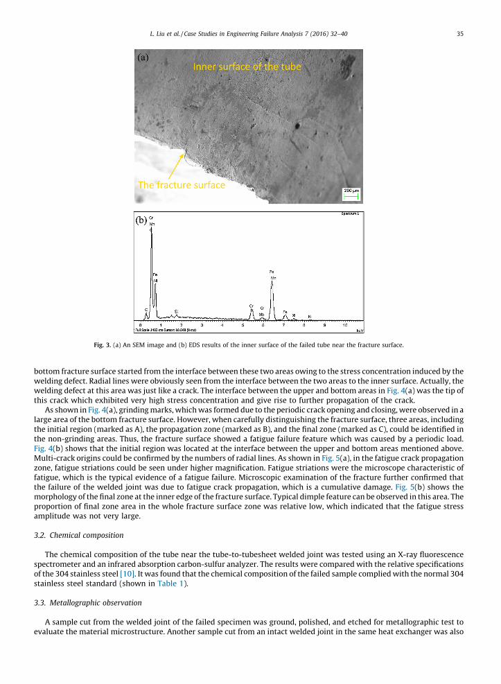
The failed tube was then observed and analyzed using the scanning electron microscopy (SEM). As shown in Fig. 3(a), theinner surface is flat and no obvious corrosion pits were found in the inner surface. The chemical composition nearthe fracture surface was further confirmed using the energy dispersive spectrometer (EDS). As shown in Fig. 3(b), nocorrosive elements such as chlorine and sulphur were detected in the inner surface.
Fig. 4(a) shows the low magnification SEM micrograph of the fracture surface. The two different areas were seen moreclearly. The bottom area near the inner surface of the tube was clearly a fracture surface, while the upper zone was anobvious non-fusion welding defect between the tube and the tubesheet. The depth of this area was about 0.4 mm. The
[(Fig._3)TD$FIG]
Fig. 3. (a) An SEM image and (b) EDS results of the inner surface of the failed tube near the fracture surface.
L. Liu et al. / Case Studies in Engineering Failure Analysis 7 (2016) 32–40 35
bottom fracture surface started from the interface between these two areas owing to the stress concentration induced by thewelding defect. Radial lines were obviously seen from the interface between the two areas to the inner surface. Actually, thewelding defect at this area was just like a crack. The interface between the upper and bottom areas in Fig. 4(a) was the tip ofthis crack which exhibited very high stress concentration and give rise to further propagation of the crack.
As shown in Fig. 4(a), grinding marks, which was formed due to the periodic crack opening and closing, were observed in alarge area of the bottom fracture surface. However, when carefully distinguishing the fracture surface, three areas, includingthe initial region (marked as A), the propagation zone (marked as B), and the final zone (marked as C), could be identified inthe non-grinding areas. Thus, the fracture surface showed a fatigue failure feature which was caused by a periodic load.Fig. 4(b) shows that the initial region was located at the interface between the upper and bottom areas mentioned above.Multi-crack origins could be confirmed by the numbers of radial lines. As shown in Fig. 5(a), in the fatigue crack propagationzone, fatigue striations could be seen under higher magnification. Fatigue striations were the microscope characteristic offatigue, which is the typical evidence of a fatigue failure. Microscopic examination of the fracture further confirmed thatthe failure of the welded joint was due to fatigue crack propagation, which is a cumulative damage. Fig. 5(b) shows themorphology of the final zone at the inner edge of the fracture surface. Typical dimple feature can be observed in this area. Theproportion of final zone area in the whole fracture surface zone was relative low, which indicated that the fatigue stressamplitude was not very large.
3.2. Chemical composition
The chemical composition of the tube near the tube-to-tubesheet welded joint was tested using an X-ray fluorescencespectrometer and an infrared absorption carbon-sulfur analyzer. The results were compared with the relative specificationsof the 304 stainless steel [10]. It was found that the chemical composition of the failed sample complied with the normal 304stainless steel standard (shown in Table 1).
3.3. Metallographic observation
A sample cut from the welded joint of the failed specimen was ground, polished, and etched for metallographic test toevaluate the material microstructure. Another sample cut from an intact welded joint in the same heat exchanger was also
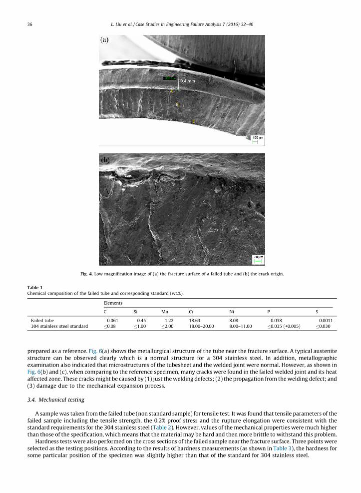
[(Fig._4)TD$FIG]
Fig. 4. Low magnification image of (a) the fracture surface of a failed tube and (b) the crack origin.
Table 1
Chemical composition of the failed tube and corresponding standard (wt.%).
Elements
C Si Mn Cr Ni P S
Failed tube 0.061 0.45 1.22 18.63 8.08 0.038 0.0011
304 stainless steel standard �0.08 �1.00 �2.00 18.00–20.00 8.00–11.00 �0.035 (+0.005) �0.030
L. Liu et al. / Case Studies in Engineering Failure Analysis 7 (2016) 32–4036
prepared as a reference. Fig. 6(a) shows the metallurgical structure of the tube near the fracture surface. A typical austenitestructure can be observed clearly which is a normal structure for a 304 stainless steel. In addition, metallographicexamination also indicated that microstructures of the tubesheet and the welded joint were normal. However, as shown inFig. 6(b) and (c), when comparing to the reference specimen, many cracks were found in the failed welded joint and its heataffected zone. These cracks might be caused by (1) just the welding defects; (2) the propagation from the welding defect; and(3) damage due to the mechanical expansion process.
3.4. Mechanical testing
A sample was taken from the failed tube (non standard sample) for tensile test. It was found that tensile parameters of thefailed sample including the tensile strength, the 0.2% proof stress and the rupture elongation were consistent with thestandard requirements for the 304 stainless steel (Table 2). However, values of the mechanical properties were much higherthan those of the specification, which means that the material may be hard and then more brittle to withstand this problem.
Hardness tests were also performed on the cross sections of the failed sample near the fracture surface. Three points wereselected as the testing positions. According to the results of hardness measurements (as shown in Table 3), the hardness forsome particular position of the specimen was slightly higher than that of the standard for 304 stainless steel.
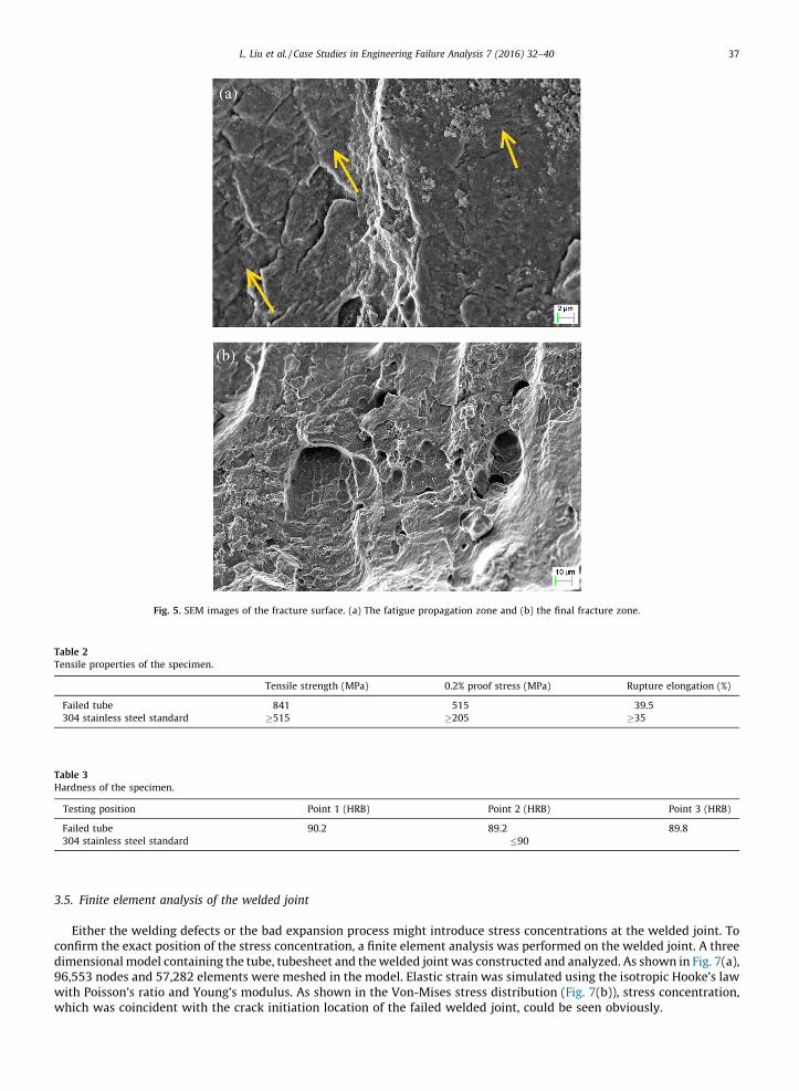
[(Fig._5)TD$FIG]
Fig. 5. SEM images of the fracture surface. (a) The fatigue propagation zone and (b) the final fracture zone.
Table 3
Hardness of the specimen.
Testing position Point 1 (HRB) Point 2 (HRB) Point 3 (HRB)
Failed tube 90.2 89.2 89.8
304 stainless steel standard �90
Table 2
Tensile properties of the specimen.
Tensile strength (MPa) 0.2% proof stress (MPa) Rupture elongation (%)
Failed tube 841 515 39.5
304 stainless steel standard �515 �205 �35
L. Liu et al. / Case Studies in Engineering Failure Analysis 7 (2016) 32–40 37
3.5. Finite element analysis of the welded joint
Either the welding defects or the bad expansion process might introduce stress concentrations at the welded joint. Toconfirm the exact position of the stress concentration, a finite element analysis was performed on the welded joint. A threedimensional model containing the tube, tubesheet and the welded joint was constructed and analyzed. As shown in Fig. 7(a),96,553 nodes and 57,282 elements were meshed in the model. Elastic strain was simulated using the isotropic Hooke’s lawwith Poisson’s ratio and Young’s modulus. As shown in the Von-Mises stress distribution (Fig. 7(b)), stress concentration,which was coincident with the crack initiation location of the failed welded joint, could be seen obviously.
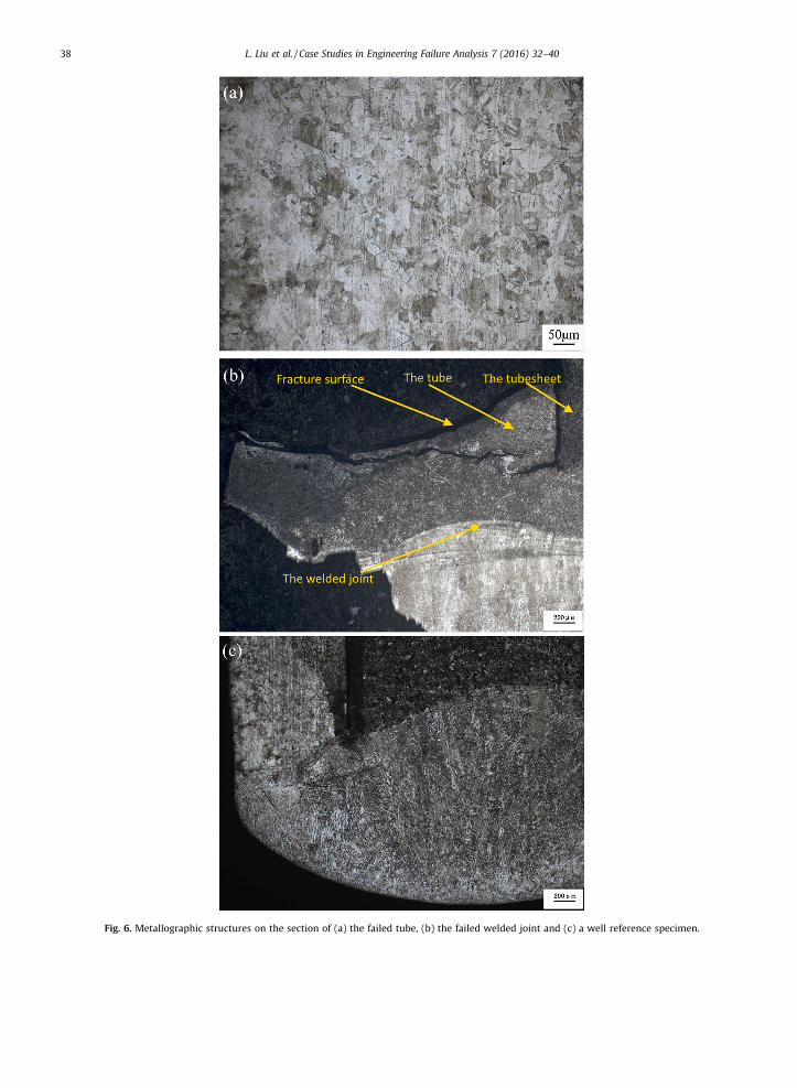
[(Fig._6)TD$FIG]
Fig. 6. Metallographic structures on the section of (a) the failed tube, (b) the failed welded joint and (c) a well reference specimen.
L. Liu et al. / Case Studies in Engineering Failure Analysis 7 (2016) 32–4038
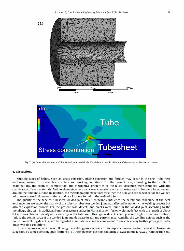
[(Fig._7)TD$FIG]
Fig. 7. (a) Finite element mesh of the welded joint model; (b) Von-Mises stress distribution of the tube-to-tubesheet structure.
L. Liu et al. / Case Studies in Engineering Failure Analysis 7 (2016) 32–40 39
4. Discussions
Multiple types of failure, such as stress corrosion, pitting corrosion and fatigue, may occur in the shell-tube heatexchanger owing to its complex structure and working conditions. For the present case, according to the results ofexaminations, the chemical composition, and mechanical properties of the failed specimen were complied with thecertification of such materials. And no elements which can cause corrosion such as chlorine and sulfur were found on andaround the fracture surface. In addition, the metallographic structures for either the tube and the tubesheet or the weldedjoint were normal. However, defects and cracks were found in the welded joint.
The quality of the tube-to-tubesheet welded joint may significantly influence the safety and reliability of the heatexchanger. As we know, the quality of the tube-to-tubesheet welded joint was affected by not only the welding process butalso the expansion process. For the present case, defects and cracks were found in the welded joint according to themetallographic test. In addition, from the fracture surface in Fig. 4(a), a non-fusion welding defect with the length of about0.4 mm was observed clearly at the out edge of the tube wall. This type of defects could generate high stress concentration;reduce the contact area of the welded joint and decrease its fatigue performance. Actually, the welding defects such as thenon-fusion welding defects could be regarded as initial cracks in the component. These cracks may further propagate underouter working conditions.
Expansion process, which was following the welding process, was also an important operation for the heat exchanger. Assuggested by some operating specifications [11], the expansion position should be at least 15 mm far away from the tube end
L. Liu et al. / Case Studies in Engineering Failure Analysis 7 (2016) 32–4040
to prevent the welded joint. However, for the present case, the expansion was started just from the tube end, which mightintroduce stress superposition and damage the welded joint. Initial micro-cracks at the welded joint might also be formedduring this process.
According to the analysis results, the failure of the tube-to-tubesheet welded joint was caused by fatigue crackspropagation. The periodic load was a necessary condition during fatigue cracks propagation. In the present case, suchperiodic load might come from the resonant vibration of the tubes which was caused by the periodic impacts of the fluid. Itmight also come from the changes in temperature and pressure of the fluid inside the heat exchanger. Combining with theexistence of initial defects and cracks at the welded joint, fatigue failure occurred finally.
5. Conclusions
In summary, the collected evidence suggests that the failure mechanism of the tube-to-tubesheet in the shell-tube heatexchanger was fatigue fracture. The fracture surfaces showed obvious crack propagation traces. Fatigue striations, whichwere the micro-evidence of fatigue, were observed clearly. The fatigue crack initiated from the defects at the tube-to-tubesheet welded joint. The periodic load might come from the resonant vibration of the tube or the changes in temperatureand pressure of the fluid inside the heat exchanger. Bad welding and unsuitable expansion position of the tubes at the tube-to-tubesheet might give rise to the formation of initial cracks. In future, prevention of failure of the shell-tube heat exchangerwould still be an important topic. Improving the quality of welding and expansion processes were effective way to reduce thefailure problems of the tube-to-tubesheet welded joint in such heat exchangers.
Acknowledgements
This work was supported by the National Natural Science Foundation of China (Grant No. 11404192), the ShandongProvince Special Grant for High-Level Overseas Talents (Grant No. tshw20120745), the Research Award Fund forOutstanding Young and Middle-aged Scientists of Shandong Province, China (Grant No. BS2014CL002), the Key Research andDevelopment Project of Shandong Province, China (Grant No. 2015GSF120002), the Science and Technology ActivitiesFoundation of China for Returned Personnel and the research fund of Shandong Academy of Sciences (2015QN003).
References
[1] Azevedo CRF, Neto FB, Brandi SD, Tschiptschin AP. Cracking of 2.25Cr–1.0Mo steel tube/stationary tube-sheet weldment of a heat-exchanger. Eng FailAnal 2008;15:695–710.
[2] Dourewling NE. Fatigue and fracture.In: ASM handbook. ASM Int 2002;19:200–62.[3] Yokell S. Heat exchanger tube–tubesheet connection. Chem Eng 1982;75:78–94.[4] Lee HS, Jung JS, Kim DS, Yoo KB. Failure analysis on welded joints of 347H austenitic boiler tubes. Eng Fail Anal 2015;57:413–22.[5] Wei XL, Ling X. Investigation of welded structures on mechanical properties of 304L welded tube-to-tubesheet joints. Eng Fail Anal 2015;52:90–6.[6] Peltola H, Lindgren M. Failure analysis of a copper tube in a finned heat exchanger. Eng Fail Anal 2015;51:83–97.[7] Xu SG, Wang C, Wang WQ. Failure analysis of stress corrosion cracking in heat exchanger tubes during start-up operation. Eng Fail Anal 2015;51:1–8.[8] Adullah S, Ezuber HM. Repair of tube–tubesheet weld cracks in a cracked gas/steam heat exchanger. J Fail Anal Prev 2011;11:611–7.[9] Hu SM, Wang SH, Yang ZG. Failure analysis on unexpected wall thinning of heat-exchange tubes in ammonia evaporators. Case Stud Eng Fail Anal
2015;3:52–61.[10] The standard of People’s Republic of China. GB/T 24593-2009 welded austenitic stainless steel tubes for boiler and heat-exchanger [in Chinese].[11] GB/T 151-2014 heat exchanger. The standard of People’s Republic of China [in Chinese].