Case Studies in Construction Materials
18
Contents lists available at ScienceDirect Case Studies in Construction Materials journal homepage: www.elsevier.com/locate/cscm Case study Experimental behavior of full-scale exterior beam-column space joints retrofitted by ferrocement layers under cyclic loading Ibrahim G. Shaaban a, ⁎ , Osama A. Seoud b a University of Liverpool (On Sabbatical, Benha University), Egypt b Civil Engineering Department, National Research Centre, Egypt ARTICLE INFO Keywords: Retrofitting Beam-column space joints Ferrocement layers Orientation of expanded wire mesh Ultimate capacity Stiffness degradation Cyclic loading Shear deficient Traditionally reinforced buildings ABSTRACT A majority of the traditional reinforced concrete frame buildings, existing across the Middle East, lack adequate confinement in beam-column joints, or in other words, are shear deficient because they were constructed before the introduction of seismic codes for construction. This research studies the experimental behavior of full-scale beam-column space (three-dimensional) joints under displacement-controlled cyclic loading. Eleven joint specimens, included a traditionally reinforced one (without adequate shear reinforcement), a reference one with sufficient shear reinforcement according to ACI 318, and nine specimens retrofitted by ferrocement layers, were experimentally tested to evaluate a retrofit technique for strengthening shear deficient beam column joints. The studied variables were the number of layers, orientation angle of expanded wire mesh per layer, and presence of steel angles in the corners of joint specimen prior to wrapping with ferrocement layers. The experimental results showed that proper shear re- inforcement for the test joints, according to ACI 318, enhanced the behavior of the specimen over that of the traditionally reinforced specimens without adequate shear reinforcement. The joints retrofitted by ferrocement layers showed higher ultimate capacity, higher ultimate displacement prior to failure (better ductility), and they did not suffer heavily damage as observed for the traditionally reinforced one. Increasing the number of ferrocement layers for retrofitted speci- mens led to improving performance for such specimens compared to the traditionally reinforced ones in terms of enhancing the ultimate capacity and ultimate displacement. Specimens retro- fitted by ferrocement layers reinforced by expanded wire mesh of 60° orientation angle showed slightly better performance than those of 45° orientation angles. Retrofitting using steel angles in addition to ferrocement layers improves the seismic performance of the specimens, achieves better stability for stiffness degradation, attains higher capacity of the dissipated energy, and reduces the vulnerability of joints to excessive damage. Based on the experimental work in this study, it is recommended to retrofit beam-column joint specimens by two ferrocement layers in addition to steel angles as stiffeners taking the orientation angle of expanded wire mesh into consideration. 1. Introduction Most of the reinforced concrete buildings, existing across the Middle East countries such as Egypt, Kingdom of Saudi Arabia, and Turkey are shear deficient because they were constructed before the introduction of seismic codes for construction [1,2]. For https://doi.org/10.1016/j.cscm.2017.11.002 Received 25 September 2017; Received in revised form 4 November 2017; Accepted 9 November 2017 ⁎ Corresponding author. E-mail addresses: [email protected] (I.G. Shaaban), [email protected] (O.A. Seoud). Case Studies in Construction Materials 8 (2018) xxx–xxx Available online 14 November 2017 2214-5095/ © 2017 The Authors. Published by Elsevier Ltd. This is an open access article under the CC BY license (http://creativecommons.org/licenses/BY/4.0/). T
Transcript of Case Studies in Construction Materials

Contents lists available at ScienceDirect
Case Studies in Construction Materials
journal homepage: www.elsevier.com/locate/cscm
Case study
Experimental behavior of full-scale exterior beam-column spacejoints retrofitted by ferrocement layers under cyclic loading
Ibrahim G. Shaabana,⁎, Osama A. Seoudb
aUniversity of Liverpool (On Sabbatical, Benha University), Egyptb Civil Engineering Department, National Research Centre, Egypt
A R T I C L E I N F O
Keywords:RetrofittingBeam-column space jointsFerrocement layersOrientation of expanded wire meshUltimate capacityStiffness degradationCyclic loadingShear deficientTraditionally reinforced buildings
A B S T R A C T
A majority of the traditional reinforced concrete frame buildings, existing across the Middle East,lack adequate confinement in beam-column joints, or in other words, are shear deficient becausethey were constructed before the introduction of seismic codes for construction. This researchstudies the experimental behavior of full-scale beam-column space (three-dimensional) jointsunder displacement-controlled cyclic loading. Eleven joint specimens, included a traditionallyreinforced one (without adequate shear reinforcement), a reference one with sufficient shearreinforcement according to ACI 318, and nine specimens retrofitted by ferrocement layers, wereexperimentally tested to evaluate a retrofit technique for strengthening shear deficient beamcolumn joints. The studied variables were the number of layers, orientation angle of expandedwire mesh per layer, and presence of steel angles in the corners of joint specimen prior towrapping with ferrocement layers. The experimental results showed that proper shear re-inforcement for the test joints, according to ACI 318, enhanced the behavior of the specimen overthat of the traditionally reinforced specimens without adequate shear reinforcement. The jointsretrofitted by ferrocement layers showed higher ultimate capacity, higher ultimate displacementprior to failure (better ductility), and they did not suffer heavily damage as observed for thetraditionally reinforced one. Increasing the number of ferrocement layers for retrofitted speci-mens led to improving performance for such specimens compared to the traditionally reinforcedones in terms of enhancing the ultimate capacity and ultimate displacement. Specimens retro-fitted by ferrocement layers reinforced by expanded wire mesh of 60° orientation angle showedslightly better performance than those of 45° orientation angles. Retrofitting using steel angles inaddition to ferrocement layers improves the seismic performance of the specimens, achievesbetter stability for stiffness degradation, attains higher capacity of the dissipated energy, andreduces the vulnerability of joints to excessive damage. Based on the experimental work in thisstudy, it is recommended to retrofit beam-column joint specimens by two ferrocement layers inaddition to steel angles as stiffeners taking the orientation angle of expanded wire mesh intoconsideration.
1. Introduction
Most of the reinforced concrete buildings, existing across the Middle East countries such as Egypt, Kingdom of Saudi Arabia, andTurkey are shear deficient because they were constructed before the introduction of seismic codes for construction [1,2]. For
https://doi.org/10.1016/j.cscm.2017.11.002Received 25 September 2017; Received in revised form 4 November 2017; Accepted 9 November 2017
⁎ Corresponding author.E-mail addresses: [email protected] (I.G. Shaaban), [email protected] (O.A. Seoud).
Case Studies in Construction Materials 8 (2018) xxx–xxx
Available online 14 November 20172214-5095/ © 2017 The Authors. Published by Elsevier Ltd. This is an open access article under the CC BY license (http://creativecommons.org/licenses/BY/4.0/).
T
example, Joints in typical buildings, constructed before issuing the current Egyptian Code of Practice [3] suffer from lack of adequatesteel reinforcement detailing to resist dynamic excitations. In these joints, the confining reinforcement such as column stirrups doesnot extend in the joint region. The pattern of joint damage in building subjected to the major earthquake in Egypt, October 1992,showed that inadequate shear reinforcement or the lack of joint confinement in the beam-column joints, especially exterior ones,were the major reasons for joint damage [4]. Hence many amendments in design and detailing of structural elements subjected tolateral loads caused by earthquakes were introduced in the international codes of practice [5–7]. In recent years, there has been arapid growth of interest in seismic performance of beam-column joints [8]. Many research projects have been conducted to in-vestigate the experimental, theoretical behavior and finite element modeling of corner and exterior beam-column joints under dif-ferent loading conditions [2,4,9–12]. During an earthquake, beam-column joints are normally suffer from severe reversed cyclicloading and become the weakest links in the structural system. This affects the overall response of a ductile moment-resisting framebuilding. Therefore, the consultants, the building officials, investors, and owners are considering retrofitting for the critical structuralelements of these existing structures to withstand the earthquake loads in order to provide safety to building occupants and to protecttheir investment [4]. There is a need for an economic and friendly environment strengthening technique to upgrade joint shear-resistance in existing structures to be able to stand for probable future earthquakes.
Classic techniques have been employed to upgrade shear capacity and ductility of RC joints, with the most common beingconstruction of reinforced concrete or steel jackets [13]. Sasmal and Nath [14] introduced a steel bracing technique to strengthenpoorly designed beam-column joints. Their finite element modeling of the specimens using ATENA package demonstrated the ad-vantage of the strengthening system for improvement of crack patterns, ultimate load, energy dissipation, and ductility of the studiedspecimens. However, these techniques cause various difficulties in practical implementation at the joint, namely intensive labor,artful detailing and increased dimensions. To overcome the difficulties associated with these techniques, recent research efforts havefocused on the use of epoxy-bonded FRP sheets, textile-reinforced mortar and ferrocement jackets to enhance the shear capacity ofpoorly detailed joints [5,7,9]. The use of ferrocement jackets (steel wire mesh embedded in cement mortar or ferrocement overlays) isa promising approach as all the used materials are cheap [8,15]. Research studies for strengthening of interior and exterior jointsusing ferrocement were cited in the literature [2,10,16,17]. However, there is a lack of research in the behavior of full-scale ret-rofitted beam-column joints, in the presence of transversal beams to simulate real reinforced concrete frame buildings, under seismicloading.
This paper studies the experimental behavior of full-scale exterior space joints retrofitted by ferrocement jackets under cyclicloading. The experimental work is a part of the PhD thesis submitted by the second author and supervised by the first author [4].Although the existence of a secondary (transversal) beam perpendicular to the plane of loading (see Fig. 1) in space joints resemblesthe joint in real structures, it represents an obstacle for easily wrapping of steel-wire mesh. Therefore, the main challenge in thisresearch is the proper method of applying ferrocement layers around the elements of the connections (the transversal beam, long-itudinal beam and the column). The objectives of this research are to compare the performance of exterior beam-column joints intraditional existing buildings with those cast according to ACI 318 [18] and the behavior of such joints after retrofitting by ferro-cement layers under displacement-controlled cyclic loading. The studied variables were the number of expanded wire mesh layers(ferrocement layers), orientation angle of expanded wire mesh per layer, and existence of steel angles at the corners of the joints priorto wrapping with ferrocement layers. Crack pattern, energy dissipation, stiffness, and strength degradation for different studiedspecimens over the loading cycles until joint collapse initiation were recorded and plotted.
2. Experimental program
The experimental program consisted of eleven beam-column space joints subjected to cyclic loading. The test specimens simulateexterior beam-column space joints in a multistory building. The beam length represents half the span length of the bay, while thecolumn height represents the column height from the mid height of one story to the mid height of the next one. The boundaryconditions are set to simulate the point of contra-flexure in the beams and the column with an acceptable accuracy. Fig. 1 and Table 1show dimensions and details of test specimens and the used formwork. One of the eleven specimens was designed and detailedaccording to ACI 318 [18] (control specimen) while the other ten specimens were designed and detailed according to a detail usedtraditionally in Egypt and several countries in the middle east to carry gravity loads only without any precautions for lateral loadscaused by earthquakes (see Figs. 2 and 3). Ferrocement jackets of different layers and different orientation angles of expanded wiremesh reinforcement beside the steel angles were used for strengthening nine of the ten test specimens with traditional reinforcementwhile the tenth was left without strengthening to be considered as a control specimen along with the beam detailed to ACI 318 [18](see Table 1 and Fig. 4).
2.1. Materials
The materials used in this research are sand as fine aggregates, gravel as coarse aggregates, ordinary Portland cement, and tapdrinking water. Tests were carried out to check the properties of the used materials according to the Egyptian Standard Specifications[4]. The mix proportions to achieve a target cube strength of 30 MPA for one cubic meter were; Cement (395 kg), Sand (534 kg),Gravel (1367 kg) and water (158 l). High-grade steel and mild steel were used as main and secondary reinforcement, respectively.Epoxy resins were also used for embedding shear connectors to wrap ferrocement layers (expanded wire mesh reinforcement) inorder to achieve full composite action with the concrete elements. The reinforcement of ferrocement used in this study was expandedwire mesh conforming according to ACI committee 549.1R-88 [19].
I.G. Shaaban, O.A. Seoud Case Studies in Construction Materials 8 (2018) xxx–xxx
2

2.2. Retrofitting of test specimens
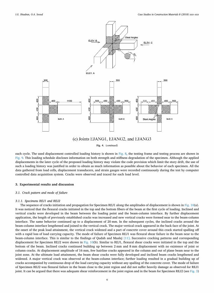
After 28 days, the concrete cover around the joint was removed for the nine exterior specimens using a small hand-held chippinghammer. The removed cover extends 300 mm in the beam and 300 mm in the column above and below the joint. The surface of steelreinforcement was exposed and cleaned (see Fig. 5(a)). The edges of the removed cover were kept curved and roughened to preventstress concentration. For the specimens prepared for retrofitting, staggered holes were drilled in each specimen in predefined lo-cations (10–15 cm apart) as shown in Fig. 5(b) and (c)). Each hole of diameter 8 mm penetrated the core with 50 mm depth. Theinner surfaces of the holes were roughened and cleaned from loose concrete pieces and dust using compressed air. The mixedanchoring grout was poured steadily into holes and a 6 mm galvanized high strength threaded bars (steel dowels) were insertedinside the holes to ensure composite action between the ferrocement layer and concrete core (see Fig. 5). The retrofitted specimenswere wrapped by one layer of wire mesh (with overlap of 100 mm) as shown in Fig. 6. The expanded wire mesh was fixed to theembedded 6 mm, shear connectors by washers and nuts. The strengthened specimens were plastered with a thin layer of rich cementmortar (650 kg of Portland cement per 1m3 of well graded sand with 0.4 as water cement ratio). The wrapped specimen was cured bywater for 4 days. The same process was repeated for each layer of ferrocement. The specimens EJANG1, EJANG2, and EJANG3 were
Fig. 1. Schematic diagrams for test specimens and formwork.
I.G. Shaaban, O.A. Seoud Case Studies in Construction Materials 8 (2018) xxx–xxx
3

retrofitting using steel angles 50*50*5 mm at the top and at the bottom fibers of the loaded beam in addition to the ferrocementlayers (see Fig. 4(c)). It is worth mentioning that the surface preparation process of specimens is the most critical phase of retrofittingwhich needs proper understanding and care to meet the necessary requirements for retrofitting. In addition, good training is ne-cessary for applying this technique in site for real structural joints.
2.3. Instrumentation, test setup and procedure
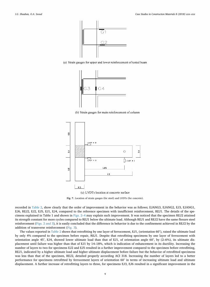
Electrical strain gauges were adhered to the reinforcing bars of specimens at appropriate locations (see Fig. 7(a) and (b)). Linearvoltage differential transducers (LVDTs) were used to measure the various types of deformations of the beam-column sub assemblage(see Fig. 7(c)). For all specimens, the loading was controlled by the displacement of the beam at the intended loading point. An axialload equals to 0.5 ultimate load of the column was applied to the column and kept constant throughout the test. Reversed cyclicdisplacements were applied to the free end of the beam simulating an earthquake-type loading. The same process was repeated for
Fig. 2. Reinforcement details of a beam-column joint without adequate shear reinforcement (less confinement), REJ1.
Fig. 3. Reinforcement details of beam-column joint according to ACI requirements REJ2.
Table 1Details of the studied Beam-Column Joints.
Reference Group (2 specimens)
Joints DescriptionREJ1 Detailed according to local practice in traditional buildings.REJ2 Detailed according to ACI 318 and its subsequent editions requirements.Retrofitted Group (9 specimens)Joints Main Reinforcement according to: No. of ferrocement
layersOrientation angle of expandedwire mesh
Presence of steel angles in the joint zone
EJ1 Detailed according to local practice intraditional buildings
One layer 60° No steel anglesEJ2 Two layers 60°EJ3 Three layers 60°EJ4 One layer 45°EJ5 Two layers 45°EJ6 Three layers 45°EJANG1 One layer 60° Two steel angles 50*50*5 mm at top and
bottom of the jointEJANG2 Two layers 60°EJANG3 Three layers 60°
I.G. Shaaban, O.A. Seoud Case Studies in Construction Materials 8 (2018) xxx–xxx
4

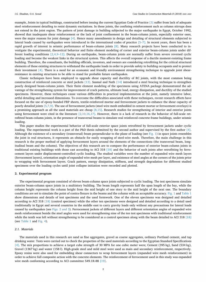
Fig. 4. Schematic diagram for ferrocement layers of different orientation angles around studied space joints (see Table 1).
I.G. Shaaban, O.A. Seoud Case Studies in Construction Materials 8 (2018) xxx–xxx
5
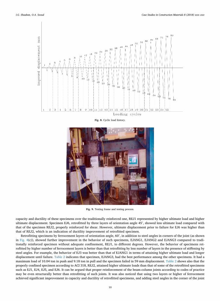
each cycle. The used displacement controlled loading history is shown in Fig. 8, the testing frame and testing process are shown inFig. 9. This loading schedule discloses information on both strength and stiffness degradation of the specimen. Although the applieddisplacements in the later cycle of the proposed loading history may violate the code provision which limit the story drift, the use ofsuch a loading history was justified in order to obtain as much information as possible about the behavior of each specimen. All thedata gathered from load cells, displacement transducers, and strain gauges were recorded continuously during the test by computercontrolled data acquisition system. Cracks were observed and traced for each load level.
3. Experimental results and discussion
3.1. Crack pattern and mode of failure
3.1.1. Specimens REJ1 and REJ2The sequence of cracks initiation and propagation for Specimen REJ1 along the amplitudes of displacement is shown in Fig. 10(a).
It was noticed that the flexural cracks initiated in the top and the bottom fibers of the beam at the first cycle of loading. Inclined andvertical cracks were developed in the beam between the loading point and the beam-column interface. By further displacementapplication, the length of previously established cracks was increased and new vertical cracks were formed near to the beam-columninterface. The same behavior continued up to a displacement of 20 mm. In the subsequent cycles, the inclined cracks around thebeam-column interface lengthened and joined to the vertical crack. The major vertical crack appeared in the back face of the joint. Atthe onset of the peak load attainment, the vertical crack widened and a part of concrete cover around this crack started spalling offwith a rapid loss of load carrying capacity. The mode of failure of Specimen REJ1 was flexural shear failure in the beam near to thebeam-column interface. This is similar to the findings of Qudah and Maalej [11]. Successive cracking patterns and correspondingdisplacement for Specimen REJ2 were shown in Fig. 10(b). Similar to REJ1, flexural shear cracks were initiated in the top and thebottom of the beam. Inclined cracks continued building up between 2 mm and 8 mm displacement with no existence of joint orcolumn cracks. At displacement amplitude of 16 mm, few hairline cracks appeared in the column and out of plane beam near to thejoint zone. At the ultimate load attainment, the beam shear cracks were fully developed and inclined beam cracks lengthened andwidened. A major vertical crack was observed at the beam-column interface; further loading resulted in a gradual building up ofcracks accompanied by continuous drop of the load carrying capacity without any spalling of the concrete cover. The mode of failureof Specimen REJ2 was flexural failure in the beam close to the joint region and did not suffer heavily damage as observed for REJ1joint. It can be argued that there was adequate shear reinforcement in the joint region and in the beam for Specimen REJ2 (see Fig. 3)
Fig. 4. (continued)
I.G. Shaaban, O.A. Seoud Case Studies in Construction Materials 8 (2018) xxx–xxx
6

compared to Specimen REJ1 (see Fig. 2). Qudah and Maalej [11] recorded similar observations in their study for application ofengineered cementitious composites (ECC) in beam– column joints for enhanced seismic resistance.
3.1.2. Specimens retrofitted by ferrocementIt was observed that the general crack patterns and mode of failure for the retrofitted specimens either those retrofitted by
different layers of ferrocement (with different orientation angles) or by combined action of ferrocement jackets and steel anglesanchored at the beam-column interface were almost similar. However, the crack initiation and propagation delayed and a less
Fig. 5. Removing concrete cover and inserting steel dowels to ensure composite action between the ferrocement layers and concrete core.
I.G. Shaaban, O.A. Seoud Case Studies in Construction Materials 8 (2018) xxx–xxx
7
number of diagonal shear cracks was observed for specimens retrofitted by combined action of ferrocement jackets and steel angles.In addition, orientation angle of expanded wire mesh has some effect on the initiation and propagation of the cracks withoutchanging the mode of failure. For example, Fig. 10(c)–(e) shows the crack patterns for typical specimens, EJ1, retrofitted by one layerof ferrocement of expanded wire mesh of orientation angle 60°, and EJ4, retrofitted by one layer of ferrocement of expanded wiremesh of orientation angle 45°. Retrofitting using ferrocement enhanced the confinement, delayed the cracks formation, decreased thecracks propagation and ultimately increased the capacity of the joint. Inclined hairline cracks were first observed at the top andbottom fibers of the beam near the ferrocement jacket far edge at the second or third cycle of loading. With increasing the load levels,the length of these inclined cracks of the beam increased and widened. New hairline cracks appeared in the strengthened zone of thebeam. A vertical crack at the beam-column interface in both front and back face of the beam was developed and widened onset theultimate load attainment. At the end of the test, it was clear that the vertical crack at beam-column interface lengthened, widened,and surrounded the beam cross section causing local peeling of the ferrocement outer layer. The mode of failure of the strengthenedspecimen was flexural in the beam close to the beam-column interface (see Fig. 10(d) and (e)). This mode of failure is very close tothat observed by Ravichandran and Jeyasehar [2] and Kannan et al. [20] while the mode of failure of strengthened beam-columnjoints using steel jackets was flexural failure at the far edge of steel plates [12].
3.2. Load-displacement records for the studied joint specimens
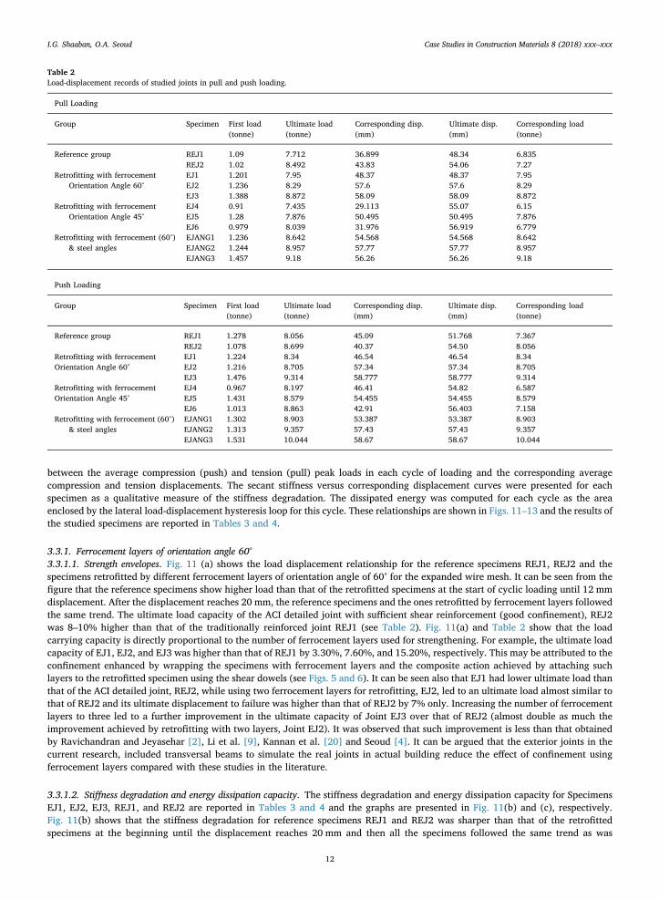
Load-displacement records for the joint specimens are reported in Table 2. It can be observed from Table 2 that the level ofultimate load ranges from 8 to 10 ton in push and from 7.7 to 9.2 ton in pull, respectively. The maximum displacement for eachspecimen before failure ranged from 48 mm to 59 mm. The values of ultimate loads and maximum displacement of each specimen,
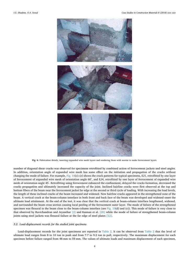
Fig. 6. Fabrication details, inserting expanded wire mesh layers and rendering them with mortar to make ferrocement layers.
I.G. Shaaban, O.A. Seoud Case Studies in Construction Materials 8 (2018) xxx–xxx
8
recorded in Table 2, show clearly that the order of improvement in the behavior was as follows; EJANG3, EJANG2, EJ3, EJANG1,EJ6, REJ2, EJ2, EJ5, EJ1, EJ4, compared to the reference specimen with insufficient reinforcement, REJ1. The details of the spe-cimens explained in Table 1 and shown in Figs. 2–4 may explain such improvement. It was noticed that the specimen REJ2 attainedits strength constant for more cycles compared to REJ1 below the ultimate load. Although REJ1 and REJ2 have the same flexure steelreinforcement (Figs. 2 and 3), it is easily concluded that the difference in behavior is due to the confinement achieved in REJ2 by theaddition of transverse reinforcement (Fig. 3).
The values reported in Table 2 shows that retrofitting by one layer of ferrocement, EJ1, (orientation 60°), raised the ultimate loadby only 4% compared to the specimen before repair, REJ1. Despite that retrofitting specimens by one layer of ferrocement withorientation angle 45°, EJ4, showed lower ultimate load than that of EJ1, of orientation angle 60°, by (2–6%), its ultimate dis-placement until failure was higher than that of EJ1 by 14–18%, which is indication of enhancement in its ductility. Increasing thenumber of layers to two for specimens EJ2 and EJ5 resulted in a further improvement compared to the specimen before retrofitting,REJ1, indicated by a higher ultimate load and higher ultimate displacement before failure but the behavior of retrofitted specimenswas less than that of the specimen, REJ2, detailed properly according ACI 318. Increasing the number of layers led to a betterperformance for specimens retrofitted by ferrocement layers of orientation 60° in terms of increasing ultimate load and ultimatedisplacement. A further increase of retrofitting layers to three, for specimens EJ3, EJ6 resulted in a significant improvement in the
Fig. 7. Location of strain gauges (for steel) and LVDTs (for concrete).
I.G. Shaaban, O.A. Seoud Case Studies in Construction Materials 8 (2018) xxx–xxx
9
capacity and ductility of these specimens over the traditionally reinforced one, REJ1 represented by higher ultimate load and higherultimate displacement. Specimen EJ6, retrofitted by three layers of orientation angle 45°, showed less ultimate load compared withthat of the specimen REJ2, properly reinforced for shear. However, ultimate displacement prior to failure for EJ6 was higher thanthat of REJ2, which is an indication of ductility improvement of retrofitted specimen.
Retrofitting specimens by ferrocement layers of orientation angle, 60°, in addition to steel angles in corners of the joint (as shownin Fig. 4(c)), showed further improvement in the behavior of such specimens, EJANG1, EJANG2 and EJANG3 compared to tradi-tionally reinforced specimen without adequate confinement, REJ1, to different degrees. However, the behavior of specimens ret-rofitted by higher number of ferrocement layers is better than that retrofitting by less number of layers in the presence of stiffening bysteel angles. For example, the behavior of EJ3 was better than that of EJANG1 in terms of attaining higher ultimate load and longerdisplacement until failure. Table 2 indicates that specimen, EJANG3, had the best performance among the other specimens. It had amaximum load of 10.04 ton in push and 9.18 ton in pull and the specimen failed in 59 mm displacement. Table 2 shows also that theproperly confined specimen according to ACI 318, REJ2, attained higher ultimate loads than that of some of the retrofitted specimenssuch as EJ1, EJ4, EJ5, and EJ6. It can be argued that proper reinforcement of the beam-column joints according to codes of practicemay be even structurally better than retrofitting of such joints. It was also noticed that using two layers or higher of ferrocementachieved significant improvement in capacity and ductility of retrofitted specimens, and adding steel angles in the corner of the joint
Fig. 8. Cyclic load history.
Fig. 9. Testing frame and testing process.
I.G. Shaaban, O.A. Seoud Case Studies in Construction Materials 8 (2018) xxx–xxx
10

specimen is recommended. However, this necessitates taking the orientation angle of expanded wire mesh into consideration.
3.3. Strength envelope, stiffness degradation and cumulative energy dissipation
Strength values of the test specimens were recorded using the strength Envelope graphs. These graphs are the relationship
Fig. 10. Crack pattern and mode of failure for selected specimens before and after retrofitting.
I.G. Shaaban, O.A. Seoud Case Studies in Construction Materials 8 (2018) xxx–xxx
11
between the average compression (push) and tension (pull) peak loads in each cycle of loading and the corresponding averagecompression and tension displacements. The secant stiffness versus corresponding displacement curves were presented for eachspecimen as a qualitative measure of the stiffness degradation. The dissipated energy was computed for each cycle as the areaenclosed by the lateral load-displacement hysteresis loop for this cycle. These relationships are shown in Figs. 11–13 and the results ofthe studied specimens are reported in Tables 3 and 4.
3.3.1. Ferrocement layers of orientation angle 60°3.3.1.1. Strength envelopes. Fig. 11 (a) shows the load displacement relationship for the reference specimens REJ1, REJ2 and thespecimens retrofitted by different ferrocement layers of orientation angle of 60° for the expanded wire mesh. It can be seen from thefigure that the reference specimens show higher load than that of the retrofitted specimens at the start of cyclic loading until 12 mmdisplacement. After the displacement reaches 20 mm, the reference specimens and the ones retrofitted by ferrocement layers followedthe same trend. The ultimate load capacity of the ACI detailed joint with sufficient shear reinforcement (good confinement), REJ2was 8–10% higher than that of the traditionally reinforced joint REJ1 (see Table 2). Fig. 11(a) and Table 2 show that the loadcarrying capacity is directly proportional to the number of ferrocement layers used for strengthening. For example, the ultimate loadcapacity of EJ1, EJ2, and EJ3 was higher than that of REJ1 by 3.30%, 7.60%, and 15.20%, respectively. This may be attributed to theconfinement enhanced by wrapping the specimens with ferrocement layers and the composite action achieved by attaching suchlayers to the retrofitted specimen using the shear dowels (see Figs. 5 and 6). It can be seen also that EJ1 had lower ultimate load thanthat of the ACI detailed joint, REJ2, while using two ferrocement layers for retrofitting, EJ2, led to an ultimate load almost similar tothat of REJ2 and its ultimate displacement to failure was higher than that of REJ2 by 7% only. Increasing the number of ferrocementlayers to three led to a further improvement in the ultimate capacity of Joint EJ3 over that of REJ2 (almost double as much theimprovement achieved by retrofitting with two layers, Joint EJ2). It was observed that such improvement is less than that obtainedby Ravichandran and Jeyasehar [2], Li et al. [9], Kannan et al. [20] and Seoud [4]. It can be argued that the exterior joints in thecurrent research, included transversal beams to simulate the real joints in actual building reduce the effect of confinement usingferrocement layers compared with these studies in the literature.
3.3.1.2. Stiffness degradation and energy dissipation capacity. The stiffness degradation and energy dissipation capacity for SpecimensEJ1, EJ2, EJ3, REJ1, and REJ2 are reported in Tables 3 and 4 and the graphs are presented in Fig. 11(b) and (c), respectively.Fig. 11(b) shows that the stiffness degradation for reference specimens REJ1 and REJ2 was sharper than that of the retrofittedspecimens at the beginning until the displacement reaches 20 mm and then all the specimens followed the same trend as was
Table 2Load-displacement records of studied joints in pull and push loading.
Pull Loading
Group Specimen First load(tonne)
Ultimate load(tonne)
Corresponding disp.(mm)
Ultimate disp.(mm)
Corresponding load(tonne)
Reference group REJ1 1.09 7.712 36.899 48.34 6.835REJ2 1.02 8.492 43.83 54.06 7.27
Retrofitting with ferrocementOrientation Angle 60°
EJ1 1.201 7.95 48.37 48.37 7.95EJ2 1.236 8.29 57.6 57.6 8.29EJ3 1.388 8.872 58.09 58.09 8.872
Retrofitting with ferrocementOrientation Angle 45°
EJ4 0.91 7.435 29.113 55.07 6.15EJ5 1.28 7.876 50.495 50.495 7.876EJ6 0.979 8.039 31.976 56.919 6.779
Retrofitting with ferrocement (60°)& steel angles
EJANG1 1.236 8.642 54.568 54.568 8.642EJANG2 1.244 8.957 57.77 57.77 8.957EJANG3 1.457 9.18 56.26 56.26 9.18
Push Loading
Group Specimen First load(tonne)
Ultimate load(tonne)
Corresponding disp.(mm)
Ultimate disp.(mm)
Corresponding load(tonne)
Reference group REJ1 1.278 8.056 45.09 51.768 7.367REJ2 1.078 8.699 40.37 54.50 8.056
Retrofitting with ferrocement EJ1 1.224 8.34 46.54 46.54 8.34Orientation Angle 60° EJ2 1.216 8.705 57.34 57.34 8.705
EJ3 1.476 9.314 58.777 58.777 9.314Retrofitting with ferrocement EJ4 0.967 8.197 46.41 54.82 6.587Orientation Angle 45° EJ5 1.431 8.579 54.455 54.455 8.579
EJ6 1.013 8.863 42.91 56.403 7.158Retrofitting with ferrocement (60°)
& steel anglesEJANG1 1.302 8.903 53.387 53.387 8.903EJANG2 1.313 9.357 57.43 57.43 9.357EJANG3 1.531 10.044 58.67 58.67 10.044
I.G. Shaaban, O.A. Seoud Case Studies in Construction Materials 8 (2018) xxx–xxx
12
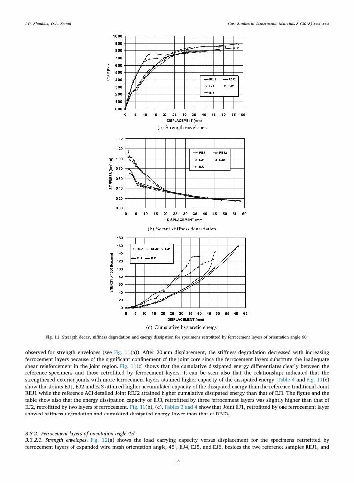
observed for strength envelopes (see Fig. 11(a)). After 20 mm displacement, the stiffness degradation decreased with increasingferrocement layers because of the significant confinement of the joint core since the ferrocement layers substitute the inadequateshear reinforcement in the joint region. Fig. 11(c) shows that the cumulative dissipated energy differentiates clearly between thereference specimens and those retrofitted by ferrocement layers. It can be seen also that the relationships indicated that thestrengthened exterior joints with more ferrocement layers attained higher capacity of the dissipated energy. Table 4 and Fig. 11(c)show that Joints EJ1, EJ2 and EJ3 attained higher accumulated capacity of the dissipated energy than the reference traditional JointREJ1 while the reference ACI detailed Joint REJ2 attained higher cumulative dissipated energy than that of EJ1. The figure and thetable show also that the energy dissipation capacity of EJ3, retrofitted by three ferrocement layers was slightly higher than that ofEJ2, retrofitted by two layers of ferrocement. Fig. 11(b), (c), Tables 3 and 4 show that Joint EJ1, retrofitted by one ferrocement layershowed stiffness degradation and cumulated dissipated energy lower than that of REJ2.
3.3.2. Ferrocement layers of orientation angle 45°3.3.2.1. Strength envelopes. Fig. 12(a) shows the load carrying capacity versus displacement for the specimens retrofitted byferrocement layers of expanded wire mesh orientation angle, 45°, EJ4, EJ5, and EJ6, besides the two reference samples REJ1, and
Fig. 11. Strength decay, stiffness degradation and energy dissipation for specimens retrofitted by ferrocement layers of orientation angle 60°.
I.G. Shaaban, O.A. Seoud Case Studies in Construction Materials 8 (2018) xxx–xxx
13

REJ2. It was observed that the ultimate load of EJ4 was less than that of the ACI detailed joint REJ2 and slightly lower than that ofEJ1 (see Fig. 11(a) and Table 2). In addition, the ultimate load of EJ4 was almost the same as that of REJ1; however, it resisted ahigher number of cycles prior to failure and its ultimate displacement was higher than that of REJ1 by 14%. This indicates that eventhat the enhancement in ultimate capacity for specimens retrofitted by ferrocement layers of orientation angle equals 45° was lessthan that for those having orientation angle 60°, the retrofitting itself enhances the ultimate displacement prior to failure whichindicates the ductility of specimens (see Table 2). Table 2 and Fig. 12(a) show that increasing the number of layers led to animprovement of the ultimate capacity of the specimens but still to a lower degree compared with that of orientation angle 60°. Figs.11 (a) and 15(a) show that the ultimate load capacities of EJ2, EJ5, EJ3 and EJ6 were higher than that of REJ1 by 7.60%, 4.30%,15.20% and 7.5% while the ultimate load capacity of the ACI detailed space Joint REJ2 was 8.90% higher than that of the local Joint,REJ1. This shows that the improvement of specimens retrofitted by two and three layers of ferrocement with expanded wire meshorientation, 60°, was higher than that of those retrofitted by two or three layers of wire mesh orientation, 45°. This may be attributedto the geometrical shape of the wire mesh, which makes its main reinforcement direction for 60° orientation, is almost perpendicular
Fig. 12. Strength decay, stiffness degradation and energy dissipation for specimens retrofitted by ferrocement layers of orientation angle 45°.
I.G. Shaaban, O.A. Seoud Case Studies in Construction Materials 8 (2018) xxx–xxx
14
to the developed cracks for the REJ1 specimen (see Figs. 4 (a), 6 and 10 (a)). In addition, the adequate shear reinforcement for thejoint region from the start (REJ2) may be better than the repair and retrofitting of beam-column joints, which were not properlyreinforced against lateral loads, REJ1.
3.3.2.2. Stiffness degradation and energy dissipation capacity. The effect of orientation angle and confinement provided by theferrocement layers can be observed in the stiffness degradation and energy dissipation capacity curves for upper mentionedspecimens EJ4, EJ5, EJ6, REJ1, and REJ2 plotted in Fig. 12(b) and (c), respectively. The results are also reported in Tables 3 and 4. Itcan be seen from the figures that the specimens retrofitted by ferrocement layers of orientation angle 45° showed almost a similartrend as shown for specimens retrofitted by ferrocement layers of orientation angle 60° (see Fig. 11(b) and (c)) in terms ofexperiencing a uniform pattern of stiffness degradation and cumulative energy dissipation. However, specimens wrapped byferrocement layers of orientation angle 60°, showed a better behavior in terms of attaining slightly higher accumulated capacity ofthe dissipated energy and slightly lower stiffness degradation than that of the specimens retrofitted by ferrocement layers oforientation 45°, especially in the late stages (see Tables 3 and 4).
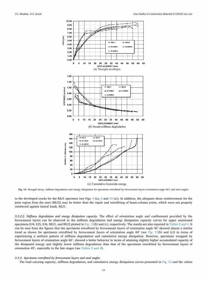
3.3.3. Specimens retrofitted by ferrocement layers and steel anglesThe load carrying capacity, stiffness degradation, and cumulative energy dissipation curves presented in Fig. 13 and the values
Fig. 13. Strength decay, stiffness degradation and energy dissipation for specimens retrofitted by ferrocement layers (orientation angle 60°) and steel angles.
I.G. Shaaban, O.A. Seoud Case Studies in Construction Materials 8 (2018) xxx–xxx
15

reported in Tables 2–4 illustrate the potential of strengthened joints in presence of steel angles (EJANG1, EJANG2, and EJANG3) overthe reference joints REJ1 and REJ2. The figure and the tables show that inserting angles to the corners of the specimen beforewrapping it by ferrocement layers enhances the overall performance of the strengthened joints compared to specimens retrofitted byferrocement layers only shown in Fig. 11.
3.3.3.1. Strength envelopes. Fig. 13 (a) shows the load carrying capacity versus the displacement for the studied specimens. It can beseen from the figure and Table 2 that the ultimate load values of EJANG1, EJANG2, and EJANG3 were higher than that of localreference exterior joint REJ1 by 11%, 16.10%, and 21.80% and they were higher than that of ACI detailed exterior joint REJ2 by2.10%, 6.64%, and 11.87%, respectively. It can be argued that the specimen REJ2 was well confined initially by proper reinforcementdetails. Fig. 13(a) and Table 2 show that the ultimate load of EJANG1 was higher than that of REJ1 by 11% while the ultimate load ofEJ1 was higher than that of REJ1 by 3.30% only (see Fig. 12(a) and Table 2). For the specimen, EJANG2, of two layers of ferrocementand steel angles, the ultimate load was higher than that of REJ1 by 16.10% while the ultimate load of EJ2 was higher than that ofREJ1 by 7.6% only. This can be attributed to the better stiffening and confinement of the joint region as a result of adding steel anglesin addition to the wrapping by ferrocement layers. This technique delayed and controlled the initiation and full development ofcracks, and consequently minimized the joint deformation.
3.3.3.2. Stiffness degradation and energy dissipation capacity. Fig. 13(b), (c), Tables 3 and 4 show that the confinement provided by theferrocement layers in the presence of steel angles was observed in the stiffness degradation and energy dissipation capacity curves forspecimens EJANG1, EJANG2, EJANG3 compared to REJ1, and REJ2. By comparing Fig. 11(b) with Fig. 13(b), it can be seen that thespecimens retrofitted by ferrocement layers without and with steel angles experienced a uniform pattern of stiffness degradation.However, Table 3 shows that the stiffness of the specimens retrofitted by ferrocement in the presence of steel angles (EJANG1,EJANG2 and EJANG3) was slightly higher than that for those retrofitted by ferrocement layers only (EJ1, EJ2 and EJ3) especially inthe late stages of cyclic loading. Figs. 11 (c) and 13 (c) show that the strengthened joints without and with the presence of steelangles, EJ1, EJ2, EJ3 and EJANG1, EJANG2, EJANG3 almost followed a similar trend and they attained higher capacities of thedissipated energy compared to that of the reference specimen, REJ1. However, Table 4 shows that the joints retrofitted byferrocement and steel angles attained higher capacity of the dissipated energy than that of the retrofitted joints without steel angles.Hence, the use of ferrocement layers in the presence of steel angles in retrofitting joints without shear reinforcement would enhancethe behavior of these joints and would reduce the vulnerability of these joints to excessive damage when subjected to seismic loading.
Table 3Stiffness Degradation of Beam-Column joints.
Group Specimen Stiffness after first loading cycle Stiffness after last loading cycle
Reference group REJ1 88.70% 16.60%REJ2 93.46% 20.20%
Retrofitting with ferrocement EJ1 90.40% 20.00%Orientation Angle 60° EJ2 91.37% 20.70%
EJ3 92.80% 21.90%Retrofitting with ferrocement EJ4 89.61% 19.69%Orientation Angle 45° EJ5 89.79% 20.66%
EJ6 90.85% 20.23%Retrofitting with ferrocement layers, orientation, 60°, & steel angles EJANG1 91.71% 21.40%
EJANG2 93.11% 21.89%EJANG3 95.23% 22.29%
Table 4Cumulative dissipated Energy of Beam-Column joints.
Group Specimen Cumulative dissipated energy of retrofitted specimens in relation to that ofREJ1
Reference group REJ1 1REJ2 1.14
Retrofitting with ferrocement EJ1 1.097Orientation Angle 60° EJ2 1.15
EJ3 1.21Retrofitting with ferrocement EJ4 1.07Orientation Angle 45° EJ5 1.13
EJ6 1.157Retrofitting with ferrocement layers, orientation, 60°, & steel
anglesEJANG1 1.14
EJANG2 1.19EJANG3 1.28
I.G. Shaaban, O.A. Seoud Case Studies in Construction Materials 8 (2018) xxx–xxx
16

4. Conclusions
This research aimed to compare the performance of full-scale exterior beam-column space joints in the traditionally reinforcedexisting buildings with those cast according to ACI 318 [18] and the behavior of such joints after retrofitting by ferrocement layersunder cyclic displacement-controlled cyclic loading. The studied variables were number of steel mesh layers (ferrocement layers),orientation angle of expanded wire mesh per ferrocement layer, and presence of steel angles at the corners of the joints prior towrapping with ferrocement layers. The major conclusions based on the results of this experimental study can be drawn as follows:
1. Proper shear reinforcement for the test joints, according to ACI 318 [18], enhanced the load carrying capacity, the energyabsorbing capacity of the joint, delayed the cracks propagation, and changed the mode of failure from flexural shear near to thebeam-column interface, for the traditionally reinforced specimens, to flexural failure in the beam close to the joint region.
2. The joints retrofitted by ferrocement layers showed higher ultimate capacity, higher ultimate displacement, resisted largernumber of cycles prior to failure, which was an indication of a better ductility, and they did not suffer heavily damage as observedfor the traditionally reinforced one before retrofitting.
3. The reference joint properly reinforced for shear according to ACI 318 showed better performance than some of the retrofittedspecimens especially those retrofitted by one or two layers of ferrocement with orientation angle 45° in terms of attaining higherultimate load and ultimate displacement until failure. The results from this work indicate that retrofitting improves the behaviorof defected joints but those properly reinforced according to codes of practice may be even structurally better than deficientlyretrofitted joints.
4. Increasing the number of ferrocement layers in retrofitting joint specimens led to improving performance for such specimenscompared to the traditionally reinforced one in terms of increasing the ultimate capacity and ultimate displacement. It is in-teresting to notice that the behavior of specimens wrapped by three layers of ferrocement was better than that wrapped by onelayer in the presence of steel angles in terms of attaining higher ultimate load and longer displacement until failure.
5. The orientation angle of the expanded wire mesh in ferrocement layers has a significant effect on the retrofitted joints.Ferrocement layers of 60°, orientation angle enhanced the ultimate capacity of the specimens higher than that achieved byretrofitting using ferrocement layers of 45°. This may be attributed to the geometrical shape of the wire mesh, which makes itsmain reinforcement direction for 60° orientation, is almost perpendicular to the developed cracks for the retrofitted specimen asshown from crack patterns.
6. Retrofitting specimens, without shear reinforcement, using steel angles in addition to ferrocement layers improves the seismicperformance of these specimens, achieves better stability for stiffness degradation, attains higher capacity of the dissipated en-ergy, and reduces the vulnerability of these joints to excessive damage compared to the retrofitted joints without steel angles.
7. Based on the experimental work in this study, it is recommended to retrofit exterior joint specimens by at least two ferrocementlayers in addition to steel angles inserted in the corner of the joint specimens. It is worth mentioning that orientation angle forexpanded wire mesh should be taken into consideration.
Acknowledgements
Staff and technicians of the Reinforced Concrete Testing Laboratory at Housing and Building Research Center are acknowledgedfor their great help. Professor Claisse, Coventry University is acknowledged for his proof reading of the manuscript.
References
[1] Gencoglu, Mobasher, The rehabilitation of the deficient RC exterior beam-column joints using cement based composites, The 14th World Conference onEarthquake Engineering, October 12–17, Beijing, China, 2008.
[2] K. Ravichandran, C.A. Jeyasehar, Seismic retrofitting of exterior beam column joint using ferrocement, Int. J. Eng. Appl. Sci. (IJEAS) 4 (2) (2012) 35–58.[3] ECCS 203, ECP 95; ECCS203-2001; ECP203-2006) “Egyptian Code for Design and Construction of Concrete Structures”, Building Research Center, Cairo, Egypt,
2007.[4] O. Seoud, Strength and Ductility OF Exterior and Corner Beam-Column Joints Retrofitted by Ferrocement Layers and Subjected to Cyclic Loading, (2013) (PhD
Thesis submitted to Benha University, Egypt, 224 pp).[5] S. Sheela, B.A. Geetha, Studies on the performance of RC beam-column joints strengthened using different composite materials, J. Inst. Eng. India Ser. A 93
(February–April (1)) (2012) 63–71.[6] N. Ganesan, P.V. Indira, S.P. Thadathil, Effect of ferrocement wrapping system on strength and behavior of RC frames under reversed lateral cyclic loading,
Exp.Tech. (July/August) (2011).[7] Y.A. Al-Salloum, N.A. Siddiqui, H.M. Elsanadedy, Textile-reinforced mortar versus FRP as strengthening material for seismically deficient RC beam-column
joints, J. Compos.Construct. ASCE 15 (6) (2011) 920–933.[8] C. Gupta, A. Kumar, M. Khan, Review paper on retrofitting of RCC beam column joint using ferro cement, Int. Res. J. Eng. Technol. (IRJET) 3 (3) (2016)
531–533.[9] B. Li, E.S. Lam, B. Wu, Y. Wang, Experimental investigation on reinforced concrete interior beam–column joints rehabilitated by ferrocement jackets, Eng. Struct.
56 (2013) 897–909.[10] L. Bo, Seismic Performance of Reinforced Concrete Beam-Column Joints Strengthened by Ferrocement Jackets, (2014) (PhD Thesis submitted to The Hong
Polytechnic University, 278 pp.).[11] S. Qudah, M. Maalej, Application of Engineered Cementitious Composites (ECC) in interior beam–column connections for enhanced seismic resistance, Eng.
Struct. 69 (2014) 235–245.[12] T. Subramani, S.S. Poongothai Priyanka, Analytical study of t beam column joint using FEM software, Int. J. Emerg. Trends Technol. Comput. Sci. (IJETTCS) 6
(May–June (3)) (2017) 148–156 (Email: [email protected]), www.ijettcs.org.[13] H.S. Haddad, Strengthening of The Exterior Beam-Column Connections With GFRP to Resist Cyclic Loading, (2000) A PhD Thesis Submitted to Cairo University.
I.G. Shaaban, O.A. Seoud Case Studies in Construction Materials 8 (2018) xxx–xxx
17

[14] S. Sasmal, D. Nath, Evaluation of performance of non-invasive upgrade strategy for beam–column sub-assemblages of poorly designed structures under seismictype loading, Earthquake Engng Struct. Dyn. 2016 (45) (2016) 1817–1835, http://dx.doi.org/10.1002/eqe.2730.
[15] A.E. Naaman, Ferrocement: progress review and critical need for the future, 11th International Symposium on Ferrocement and Textile Reinforced Concrete 3rdICTRC, Proceedings Pro098: FERRO-11-11th International Symposium On Ferrocement and 3rd ICTRC International Conference On Textile Reinforced Concrete(2015) 9–14.
[16] M. Noyan, Experimental Study on the Behavior of RC Beam-Column Joint Retrofitted with Ferrocement Jacket Under Cyclic Loading, (2014), p. 79 M.EnggThesis Submitted to Bangladesh University of Engineering and Technology.
[17] S.R. Dakhane, K.P. Gatlewar, A.G. Bahale, A.D. Raut, Review on analysis of ferrocement-construction material, International Conference on Science andTechnology for Sustainable Development (ICSTSD) (2016) 88–93.
[18] ACI (American Concrete Institute) Committee 318, Building Code Requirements for Structural Concrete (ACI 318-14) and Commentary (ACI 318R-14),Farmington Hills, MI : ACI, 2014.
[19] ACI Committee 549-1R-88, “Guide for Design, Construction, and Repair of Ferrocement” ACI 549-1R-88 and 1R-93 (Approved 1999), Manual of ConcretePractice, ACI, Detroit, 1993, 27pp.
[20] P. Kannan, S. Sivakumar, K.R. Bindhu, Seismic strengthening of exterior RC beam-column joints by advances ferrocement jacketing, Int. J. Innov. Res. Sci. Eng.Technol. 2 (December) (2013) (Special Issue 1).
I.G. Shaaban, O.A. Seoud Case Studies in Construction Materials 8 (2018) xxx–xxx
18