
CASE STUDIES: FAILURE ANALYSIS OF SHORT …indianpowerstations.org/Presentations Made at...
40
CASE STUDIES: FAILURE ANALYSIS OF SHORT CIRCUIT GENERATORS Presenter Arun Kumar Datta Engineering Officer Operation & Maintenance Division, Switchgear Testing & Development Station Central Power Research Institute (CPRI), Bhopal, India.
Transcript of CASE STUDIES: FAILURE ANALYSIS OF SHORT …indianpowerstations.org/Presentations Made at...

CASE STUDIES: FAILURE ANALYSIS
OF SHORT CIRCUIT GENERATORS
Presenter
Arun Kumar Datta Engineering Officer
Operation & Maintenance Division, Switchgear Testing & Development Station
Central Power Research Institute (CPRI), Bhopal, India.

POWER SYSTEM
GENERATION
TRANSMISSION DISTRIBUTION
GENERATION

POWER SYSTEM EQUIPMENTS
• GENERATOR
• BUS DUCT
• CIRCUIT BREAKER
• TRANSFORMER
• DISCONNECTOR
• CT, PT, RELAY
• LINE CONDUCTOR
• TOWER, etc.

FAULTS IN POWER SYSTEM • SINGLE LINE TO GROUND
• DOUBLE LINE TO GROUND
• THREE PHASE
• LINE TO LINE
• SIMULTANEOUS
• OPEN CIRCUIT
Equipments connected in the complex system are prone to
see a few short circuits in its lifetime. Hence these
equipments should be subjected to short circuit test, prior
to finalize their design. CPRI laboratories at Bhopal
create this short circuit condition and supply the fault
power to the equipment under test.
WHY TESTING?

Short circuit test at CPRI laboratory Conventional Short circuit test
SHORT CIRCUIT
• High power flow from the appended equipment till the fault point.
• Huge wastage of energy in the form of heat and force.
• Instability in the grid may cause failure, etc.

SHORT CIRCUIT CURRENT & POWER
If V is the rated voltage applied and Z is the transformer impedance referred
to the primary side (for simplicity the source & external circuit impedances
are neglected) then, in secondary short circuited condition, current drawn
from the source side will be
Isc = V = V = I x 100 = Rated current x 100
Z %Z x V %Z %age impedance
100 I
Short circuit Power in VA = V x Isc.
Example: A 1-ph, 13.2MVA, 132kV/33kV, 100A(pri) transformer with %age
impedance 5, will draw
100x100 = 2000A in the primary under secondary
5 short circuited condition.
Short circuit power drawn
= 132000 x 2000 = 264x106 VA or 264MVA
Where as the test transformer was only of 13.2 MVA rated.

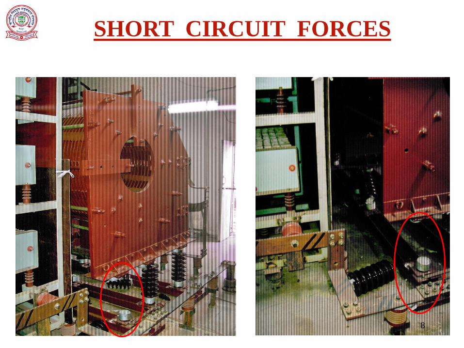
SHORT CIRCUIT FORCES
7
BROKEN INSULATOR
8
SHORT CIRCUIT FORCES

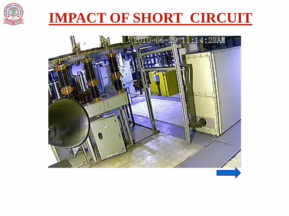
IMPACT OF SHORT CIRCUIT

IMPACT OF SHORT CIRCUIT

IMPACT OF SHORT CIRCUIT

IMPACT OF SHORT CIRCUIT

SOURCES OF SHORT CIRCUIT POWER
Power requirement during short circuit test is very high. This power can be drawn directly from grid or from S.C. generator.
100MVA ONLINE TESTING STN.
• Drawing power from 132kV grid and further stepping down .
• Grid is loaded during test.

SOURCES OF SHORT CIRCUIT POWER
1250MVA SHORT CIRCUIT TESTING STATION
• Two specially designed 3 phase Alternators capable of supplying required fault power to test equipment (ratings 1500MVA, 12.5kV, 69kA, 3000rpm, 50Hz each).
• The supply grid is not loaded during the short circuit period.

SHORT CIRCUIT GENERATOR
CONSTRUCTIONAL FEATURES(STATOR)

SHORT CIRCUIT GENERATOR
CONSTRUCTIONAL FEATURES(ROTOR)

SHORT CIRCUIT GENERATOR Vs. CONVENTIONAL
SHORT CIRCUIT GENERATOR CONVENTIONAL GENERATOR
Short time rating Continuous rating
Extra high mechanical strength for
repeated short circuit forces
No extra mechanical reinforcement
is required
High conductor current density As per rated current
Extra care for insulation Standard insulation level
Normally motor as prime mover Turbine as prime mover
Forced air cooling Normally H2 cooled
Flexible winding configuration In a fixed configuration
Required more (33%) damper winding No extra amount of damper winding
Specially designed foundation to absorb
the jerks.
Standard foundation design.

LABORATORIES OF CPRI BHOPAL
• 1250MVA SHORT CIRCUIT TESTING STATION.
• 100MVA ONLINE TESTING STATION.
• SUPPLEMENTARY TEST LABORATORY.
• ENERGY METER TEST LABORATORY.
• CALIBRATION LABORATORY.
• OIL TEST LABORATORY

CPRI PROFILE
• The Central Power Research Institute commonly known as CPRI, is the leading provider of Global Certification services to Utilities and Manufacturers of Electrical equipment over 51 yrs. • CPRI laboratories are accredited as per International Standard
ISO/IEC: 17025 norms by National Accreditation Board for Laboratories (NABL).
• Accredited by Bureau of Indian Standards (BIS). • CPRI laboratories Accredited by ASTA INTERTEK, UK. • Approved by UL-USA, CSA-Canada. • Member of Short Circuit Testing Liaison (STL). • Serve as nodal centre for applied research in electric power
engineering and assist utilities / industries in product development. • CPRI laboratories are at par with any other international laboratory
engaged in testing and certification of power system apparatus of manufacturers and entrepreneurs.
• It is the fourth largest electrical testing laboratory in the world.
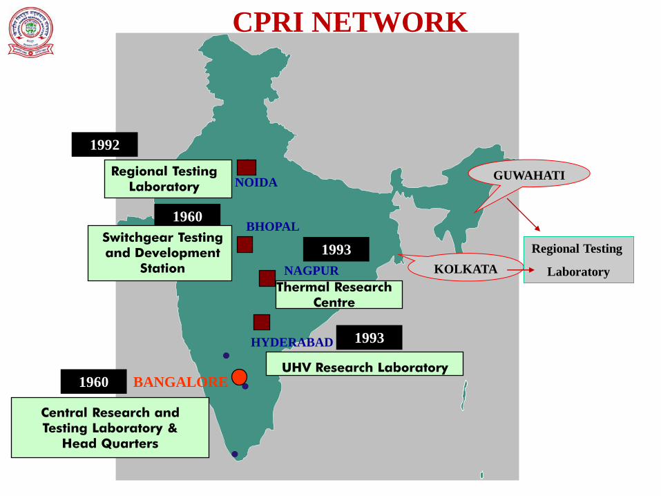
BANGALORE 1960
Central Research and Testing Laboratory &
Head Quarters
1960
Switchgear Testing and Development
Station
NOIDA
1992
Regional Testing Laboratory
NAGPUR
1993
Thermal Research Centre
HYDERABAD 1993
UHV Research Laboratory
CPRI NETWORK
BHOPAL
KOLKATA
GUWAHATI
Regional Testing
Laboratory

• Generator-1 was running at its rated speed i.e. 3000 rpm.
• Stator output voltage was set as 12kV for a station test.
• During rising side of the voltage at 8kV, rotor earth fault
protection relay operated and field breaker tripped.
• Vibration was also high for the excited period.
• Vibration and sound was normal at 3000rpm under un-
excited condition.
FAILURE CASE STUDY – I
Shot No. If (Amps) Vt (kV) Remark
1 115 2 --
2 250 5 --
3 840 8* Rotor earth fault relay operated
& abnormal vibration noticed
High vibration was due to increase in field current
i.e. 840 Amps at 8kV whereas; nominal current is only 720 Amps for 12kV.
As the rpm decreased below 1800 rpm, the rotor earth fault relay got reset.
* The plant was set for 12 kV but it was tripped at 8 kV.

Alternator has a field system supplied
with direct current and insulated from
the machine frame. A single ground fault
in the rotor circuit is not dangerous for
the machine but it must be detected and
eliminated before a second fault can
appear which would have catastrophic
for the machine.
A low voltage supply is injected from the
secondary winding of a transformer
through a capacitor. This capacitor also
blocks the DC from the field supply. In
case of earth fault in the rotor circuit,
current in the transformer secondary
winding passes through the operating coil
of the relay, thereby activating the trip
circuit.
OPERATING PRINCIPLE OF ROTOR E/F RELAY(G-1)

FAULT DIAGNOSIS AT STANDSTILL
Stator winding resistance
Terminal Design value at 75°C Measured value at 32°C Remark
U-X-U’-X’ 1.228 mΩ 1.6230 mΩ No
remarkable
change V-Y-V’-Y’ 1.228 mΩ 1.6260 mΩ
W-Z-W’-Z’ 1.228 mΩ 1.6078 mΩ
Recurrent Surge Oscillograph (RSO)
Rotor winding resistance
Terminal Design value at
75°C
Measured value at
32°C
Remark
Between slip rings 152 mΩ 149 mΩ No remarkable
change
‘A’ - Transmitted ‘B’ - Reflected CONFUSED??
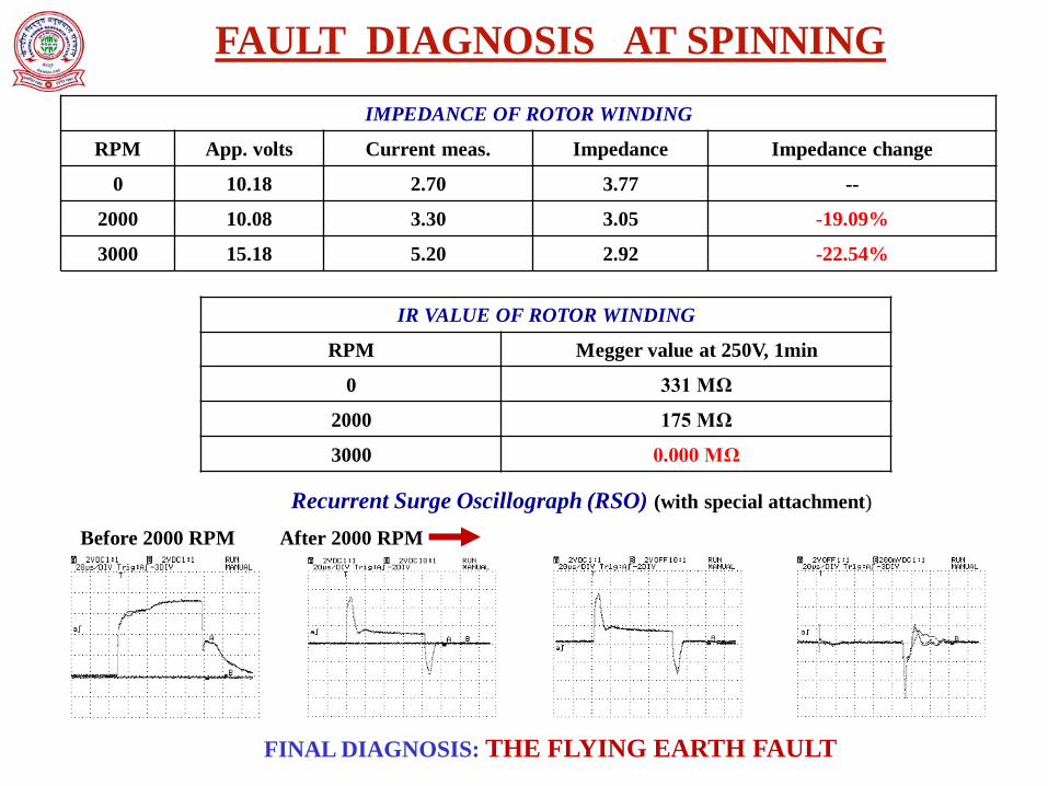
FAULT DIAGNOSIS AT SPINNING
IMPEDANCE OF ROTOR WINDING
RPM App. volts Current meas. Impedance Impedance change
0 10.18 2.70 3.77 --
2000 10.08 3.30 3.05 -19.09%
3000 15.18 5.20 2.92 -22.54%
IR VALUE OF ROTOR WINDING
RPM Megger value at 250V, 1min
0 331 MΩ
2000 175 MΩ
3000 0.000 MΩ
Recurrent Surge Oscillograph (RSO) (with special attachment)
Before 2000 RPM After 2000 RPM
FINAL DIAGNOSIS: THE FLYING EARTH FAULT

REPAIR WORK
• The flying earth fault of this rotor was a typical condition which
couldn’t be pin pointed accurately at stand still condition.
• The machine was 50 yrs old with class ‘B’ insulation, which got
deteriorated over the years.
• A complete rewind with upgraded insulation was the only full proof
method of addressing the problem.
• Any other patch work would have involved various degrees of risk.
• Disassembling of rotor was carried out with removing of retaining
rings, dismantling of slip rings, CC bolts and D leads.
• Rotor coils were of continuous type.
Rotor coil Retaining ring removal

REPAIR WORK
A few slot wedges had shown hair line cracks of about 10 mm length during DP test. Wedges (both
ends) were strengthened with brazing alloy as a preventive action for future. Rotor body was sand
blasted and thereafter applied insulating paint on it.
Rotor rewinding was done using same copper with new class ‘F’ insulation imported from
Switzerland. After assembling of all pressing tools on rotor, polymerization cycle was performed.
New insulation Polymerization process
Rewinding process Wedge with hair line crack

TESTS ON RE-WOUNDED ROTOR
Measurements after repair
Insulation Resistance Winding resistance High Voltage test
Test voltage: 500 VDC
After 15s: 430 MΩ
After 60s: 886 MΩ
133.16 mΩ at 33°C Test voltage: 1700 VAC for 1
min. Withstood,
Leakage current: 188.8mA
Vibration measurement
Surge comparison test
•Over speed test at 10 % above nominal speed was carried for two minutes.
•Rotor balancing done at 3000 rpm and vibration values were taken.
•Surge comparison tests were performed during and after balancing.
From inner slip ring From outer slip ring

TESTS ON STATOR
Electromagnetic Core Imperfection Detection
(ELCID) test • This test is carried out on the stator winding of
generator to detect imperfections, faults and hot
spots in the stator core.
• Core laminations are coated with a thin layer of
electrical insulation to prevent Eddy currents
being induced between them by rotating magnetic
field.
• ELCID test was conducted by passing an exciting
current of 13.45 Amps through 6 turns of looped
wire around the stator frame.
• Test results showed that inter-laminar insulation of
the stator core is healthy.
Wedge mapping test by electronic wedge
tightness detector • Wedge mapping test revealed that about 19.5% of
the wedges were loose and about 19.6% of the
wedges were slightly loose. Re-wedging of the
stator winding was carried out.
ELCID
WEDGE MAPPING

GENERATOR RE-COMMISSIONING • The re-wounded rotor was threaded inside the stator bore and shaft line
was aligned.
• All the required pre-commissioning tests were carried out.
• Open circuit characteristic of the generator was plotted after first
excitation.

• A 12kV VCB was under test.
• One complete test duty and one shot for
second test duty were completed without
any problem.
• During second shot for second test duty,
when the voltage was on rising side after
the excitation request, the ‘Rotor earth
fault’ indication appeared and Excitation
circuit breaker (DCCB) tripped.
• At the time of tripping the voltage was
around 4 kV.
• No abnormal vibrations and other
parameters were recorded/observed
during or prior to that incident.
FAILURE CASE STUDY – II

This static relay applies a low frequency voltage (4.75Hz, 24V p-p) to the
field winding of the machine under supervision through a relay coupler.
The measurement of the rotor IR value is achieved by measurement of
the current flowing through a shunt inside the relay. This value is
continuously compared with a preset value and activates after a set time
delay, whenever it crosses the limit.
The relay coupler is a LC circuit which allows the passage of 4.75 Hz
and blocks all other frequencies.
OPERATING PRINCIPLE OF ROTOR E/F RELAY(G-2)

FAULT DIAGNOSIS
• Rotor insulation resistance value between slip ring to earth: zero.
• Resistance of the rotor winding was checked and was found very
high comparing to its value during commissioning (33.71 mΩ).
Such high resistance indicated the opening of winding and
conduction through the rotor body.
• The D-lead connections were also inspected and found intact.
• To check the condition of the rotor winding RSO test was
conducted which confirmed the rotor winding insulation failure.
• After opening of retaining rings, it was noticed that the melted
copper had pierced the insulation under the retaining ring. When
the insulation sheet was removed, voids were observed on the coils
& between the copper strands at the brazed junction.
End ring Damper windings Insulation puncture Voids

ROOT CAUSE ANALYSIS
• This rotor was manufactured in England.
Voids presented at the brazed junction
during manufacturing process has made
stress concentration during current flow.
• Opening of the turn at the brazed junction
level.
• When the conducting surface was too small,
some copper strands melted.
• Some short circuit occurred between the
turns which had melted copper stands.
• The melted copper flew towards the outer
diameter and pierced the insulation under
the retaining rings.
• DP test was made on the retaining rings. No
crack was discovered. They are not damaged
by the electric flash because the earth fault
was made with the dampers.
Stress concentration at voids

REPAIR WORK
• Disassembled the complete rotor.
• Replaced the copper strands those were submitted to high
stresses.
• Changed the type of brazing material.
• Suppressed the stress concentration by filling all the voids
between the copper strands at the brazed junction level.
• The rotor was rewound with new Class F insulation (slot liners
and the top packers).
• After assembling of all pressing tools, rotor coil insulation
polymerization cycle was performed at 100°C.
Repairing of damaged strands Rewinding work

TESTS ON RE-WOUNDED ROTOR
• Over speed at 10 % above nominal speed was carried for two minutes.
• Rotor was balanced at 3000 rpm and vibration values were:
NDE : 7.067 microns (pk-pk) & DE : 5.115 microns (pk-pk).
• During balancing, RSO test was performed in running at nominal speed.
Measurements after repair
Insulation
Resistance
Winding
resistance
High Voltage test
Test voltage: 500
VDC
After 15s: 1.64 GΩ
After 60s: 3.0 GΩ
38.6 mΩ at
31°C
Test voltage: 1500
VAC for 1 min.
Withstood,
Leakage current:
105mA RSO during balancing

TESTS ON STATOR
• ELCID test and Wedge mapping were conducted.
• Test results showed a healthy core and tight wedges.
Hence no work was required to be done on the stator
except complete cleaning.

GENERATOR RE-COMMISSIONING
• Re-commissioning work was carried out and OCC plot
was taken.
• OCC was identical to the earlier characteristics.

• Timely activation of automatic relays saved the plant from
other damages.
• But no system can be called full proof until unless constant
vigil is maintained. People working with any system are the
best judges for it.
• Both the generators were put into service after satisfactory
commissioning. They are operating absolutely trouble free.
• The generator-2 has been Up-graded as Motor-less along
with this reformation process.
• Reliability of the short circuit testing has increased
manifold and it is available for more numbers of equipment
testing.
CONCLUSION
Intellectual solve problems, genius prevent them
-Albert Einstein.