CASE HISTORY: RETROFIT OF COAL MILL EXHAUST FAN – …Historically, the centrifugal fan design used...
17
CASE HISTORY: RETROFIT OF COAL MILL EXHAUST FAN – STUDY OF FAN PERFORMANCE AND EROSION David R. Grupp Director of Research Robinson Industries, Inc. 400 Robinson Drive Zelienople, PA 16063
Transcript of CASE HISTORY: RETROFIT OF COAL MILL EXHAUST FAN – …Historically, the centrifugal fan design used...
CASE HISTORY: RETROFIT OF COAL MILL EXHAUST FAN –
STUDY OF FAN PERFORMANCE AND EROSION
David R. Grupp Director of Research
Robinson Industries, Inc. 400 Robinson Drive
Zelienople, PA 16063
CASE HISTORY: RETROFIT OF COAL MILL EXHAUST FAN –
STUDY OF FAN PERFORMANCE AND EROSION
David R. Grupp Director of Research
Robinson Industries, Inc. 400 Robinson Drive
Zelienople, PA 16063
Abstract
Coal pulverizer mills are utilized in many coal fired power generation facilities across the country and around the world. These coal mills utilize centrifugal exhaust fans to induce and transport a very abrasive air and coal particulate mixture from the mill to the burner for combustion in the boiler. Historically, the centrifugal fan design used in these applications has been a reliable, but low efficiency paddle wheel type design commonly known as a “whizzer wheel”. Recently work has been conducted on an improved fan design intended to replace or retrofit the existing coal mill exhauster fan assembly within the constraints of the existing pulverizer mill. The new fan was designed to provide increased volume flowrate through the mill, increased efficiency in operation, and extended wear life. However, a unique erosion problem was experienced in the first application of the new centrifugal fan design. By utilizing state of the art numerical analyses in order to study the fan performance and erosion characteristics of the subject fan unit, the erosion problem was solved. The purpose of this paper is to discuss the original design and development of the high efficiency, backward curved, centrifugal exhauster fan and highlight the application of advanced computational fluid dynamic (CFD) analyses used to identify and solve the subsequent erosion problem encountered on the installed fan unit.
Introduction and Background
Since the advent of deregulation in the power industry, coal fired power plant facilities have experienced various changes including the type and quality of coal utilized for combustion. In addition, the increase in demand for power at various generating facilities has resulted in the need for increased plant performance and efficiency. The transport of the air / coal mixture is essential in providing the proper rate of combustion in the burner. With an increase in fan performance, an increase in overall mill capacity could be achieved, thus resulting in a higher rate of combustion. This, of course, led to the desire for a new fan design capable of increased performance and efficiency compared to the existing paddle wheel design.
Development of High Efficiency Exhauster
Robinson Industries was originally contacted by a large utility company for the purpose of replacing the existing “whizzer wheel” type coal mill exhauster fan with a new, higher capacity fan design. Another important consideration for the new design was to reduce the wear and erosion of the equipment in order to minimize costly downtime and maintenance on the multiple units in operation at the plant. In order to ensure proper application of the new fan design with respect to aerodynamic performance and efficiency, Robinson recommended that laboratory testing of a prototype fan unit be conducted. In addition, flow visualization studies were proposed to predict the most likely areas for high velocity coal particulate impingement and erosion in the fan rotor and casing to aid in the design of wear protection for the fan unit.
Prototype Aerodynamic Performance Testing per AMCA 210-99
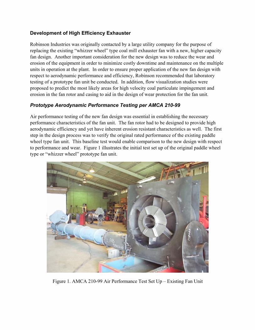
Air performance testing of the new fan design was essential in establishing the necessary performance characteristics of the fan unit. The fan rotor had to be designed to provide high aerodynamic efficiency and yet have inherent erosion resistant characteristics as well. The first step in the design process was to verify the original rated performance of the existing paddle wheel type fan unit. This baseline test would enable comparison to the new design with respect to performance and wear. Figure 1 illustrates the initial test set up of the original paddle wheel type or “whizzer wheel” prototype fan unit.
Figure 1. AMCA 210-99 Air Performance Test Set Up – Existing Fan Unit
The goal of the new design, as established by the customer, was to increase the capacity of the mill by increasing the volume flowrate of the fan by 10% of the original rated flow. The increase in capacity results in an associated increase in fan static pressure of 21% assuming the performance characteristics of the system follow a parabolic resistance curve. Based on the desired increase in performance and previous test work at Robinson, it was determined that the retrofit fan design would require a new rotor and housing combination to achieve the objective.
Air performance testing was conducted in accordance with AMCA 210-99 inside Robinson’s AMCA Accredited laboratory per Figure 7, “Outlet Duct Test Set Up – Pitot Traverse in Outlet Duct” (AMCA 210-99). Prototype scale models of the existing fan unit and various new designs were fabricated, assembled, and tested on a calibrated dynamometer set up. Results were then corrected to full size, full speed conditions using performance conversion procedures per AMCA 802-92. Complete geometric correspondence was achieved during fabrication in order to ensure linear proportionality and angular similarity. The ratio of material thicknesses and internal clearances were taken into account as well.
Complete fan dynamic or flow similarity was achieved by running the prototype units at a rotational speed high enough to generate a Fan Reynold’s Number above the minimum threshold value of 3 x 10⁶ to eliminate any apparent changes in efficiency due to size effects between the model fans and the full size fan units. In addition, Tip Speed Mach Parameter requirements were satisfied within AMCA allowable limits to provide proper scaling from model test results to full size. Compressibility effects were also considered in the calculations and conversion procedures.
Various design iterations were made to optimize the rotor blade design for the required specific speed (i.e. volume and pressure characteristics). A backward curved blade shape was finalized based on the highest efficiency achievable with a blade shape that would provide resistance to erosion and coal particulate impact damage. In addition, the housing design was optimized for the new rotor design, while maintaining the original inlet and outlet connection dimensional constraints and foundation bolting pattern. This consideration ensured that the new, retrofit fan design would be able to be installed into the existing exhauster position in the mill.
Figure 2 illustrates the measured prototype fan performance for both the existing paddle wheel type fan and the retrofit backward curved type fan design developed at Robinson. Results shown on the curve are corrected from lab model size to full size conditions. Additional corrections are made for speed, density, and temperature and are labeled on the graph for reference. From the comparison curve, it is evident that the new design provides a substantial increase in volume and pressure along the entire operating range of the fan performance curve with an associated reduction in brake horsepower. In addition, peak static efficiency of the BC fan design was measured to be 12.8% higher than the original whizzer wheel design.

Prototype Test Fan Performance Comparison CurveExisting PW Type vs. Retrofit BC Type
Results Corrected to Conditions of: 1780 RPM, 70 Deg. F, 0.075 Lb/Ft3 Density
0
5
10
15
20
25
30
35
40
0 5000 10000 15000 20000 25000 30000 35000 40000
Volume (CFM)
Fan
Stat
ic P
ress
ure
(In-H
20)
0
40
80
120
160
200
240
280
320
Bra
ke H
orse
pow
er (B
HP)
Ps - BC Type Ps - PW Type BHP - BC Type BHP - PW Type
64" Dia. BC Type61-5/8" Dia. PW Type
Figure 2. Prototype Fan Performance Curve Comparison
Evaluation of “System Effects” on Installed Retrofit Fan Unit
After completion of AMCA 210 air performance testing on the new BC fan design, further evaluation of the as-installed fan performance was still required. Since the unit was designed to be retrofit into the existing installation, additional considerations for inlet and outlet system effects had to be addressed to verify the actual installed fan / system performance. Two potential system effects to consider were a 90 degree canted elbow at the inlet of the fan and a reducing, offset transition connecting the discharge of the fan unit to the downstream ducting.
In order to quantify the effects of these components, the original AMCA 210 test set up for the BC fan was modified with the addition of the inlet elbow and the offset discharge transition. Additional testing was conducted on the prototype fan unit and a reduction in peak efficiency of 8.8% was measured. As expected, the fan brake horsepower remained constant, but the volume pressure characteristic curve was reduced due to the presence of the inlet and outlet components. The major reason for deficient performance may be attributed to the sharp, 90 degree turn at the inlet of the fan unit, which is believed to cause a distorted inlet velocity distribution into the fan rotor. Figure 3 illustrates the modified test set up for the evaluation of installed system effects. Figure 4 shows a fan performance comparison curve between the AMCA 210 (open inlet) test and the as-installed fan performance curve with system effects as predicted by laboratory prototype testing.

Figure 3. Evaluation of Installed System Effects – 90 Degree Canted Elbow at Inlet
Figure 4. Fan Performance Curve Comparison – System Effects
Prototype Test Fan Performance Comparison CurvePrediction of Installed Fan Performance with System Effects
Results Corrected to Conditions of: 1780 RPM, 150 Deg. F, 0.0633 Lb/Ft3 Density
0
5
10
15
20
25
30
35
40
0 5000 10000 15000 20000 25000 30000 35000 40000
Volume (CFM)
Fan
Stat
ic P
ress
ure
(In-H
20)
0
40
80
120
160
200
240
280
320
Bra
ke H
orse
pow
er (B
HP)
Ps - BC Type w/ SE Ps - BC Type BHP - BC Type w/ SE BHP - BC Type
64" Dia. BC Type

Erosion and Wear Studies Using Paint Injection Method
In order to ensure the success of the fan rotor design from the standpoint of erosion and wear, flow visualization studies were also conducted to characterize the localized wear patterns in the blade channels and throughout the entire rotor. High velocity impingement of paint particles injected into the rotating fan wheel can help assist in qualitatively analyzing the design of the rotor and identifying areas with a tendency for wear or build-up to occur. Areas of high relative velocity in the fan rotor tend to become heavily coated while low relative velocity, low flow regions of the rotor and blade channels typically do not become coated with paint particles.
Figure 5 illustrates the paint injection process as conducted in Robinson’s laboratory on one of the design iterations of the high efficiency, backward inclined fan unit. From the photo, high relative velocity areas of particle impingement appear on the leading edge of the blades and are concentrated toward the back plate of the rotor. In addition, inlet dust deflectors are positioned on the web plate between the blades on the fan rotor. These deflectors help to establish particulate flow through the blade channels without impacting either the leading or trailing edge of the blades. The actual design and position of these deflectors was optimized for the final rotor design by conducting multiple paint injection test iterations on the final rotor design.
Figure 5. Flow Visualization / Erosion Studies through Paint Injection Process
Particulate path lines coming off of the deflectors can also be seen on the web plate in between blades. One caveat in the paint injection test process is that the hub and hubcone areas tend to become heavily coated with paint. However, typically only light wear and erosion is experienced by these components in actual coal mill exhauster installations. In addition, the size, mass, distribution, and inertial properties of the atomized paint spray are not the same as the actual coal particles entrained into the airstream, which again reinforces the qualitative nature of the test.
Design of Wear Protection on Exhauster Rotor
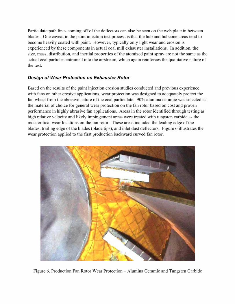
Based on the results of the paint injection erosion studies conducted and previous experience with fans on other erosive applications, wear protection was designed to adequately protect the fan wheel from the abrasive nature of the coal particulate. 90% alumina ceramic was selected as the material of choice for general wear protection on the fan rotor based on cost and proven performance in highly abrasive fan applications. Areas in the rotor identified through testing as high relative velocity and likely impingement areas were treated with tungsten carbide as the most critical wear locations on the fan rotor. These areas included the leading edge of the blades, trailing edge of the blades (blade tips), and inlet dust deflectors. Figure 6 illustrates the wear protection applied to the first production backward curved fan rotor.
Figure 6. Production Fan Rotor Wear Protection – Alumina Ceramic and Tungsten Carbide
Operation of Installed Retrofit BC Design Fan Unit
Following fabrication, testing, and assembly of the fan rotor, housing, and inlet piece, the first BC design coal mill exhauster retrofit fan unit was put into service. Verification of aerodynamic fan performance was conducted on the unit to determine if the production fan unit met the required performance as specified by the customer and predicted from laboratory prototype testing. Field air performance testing was conducted in accordance with AMCA 203-90, Field Performance Measurement of Fan Systems. The results of the test were determined to be satisfactory and closely agreed with the laboratory prototype test of the model fan unit.
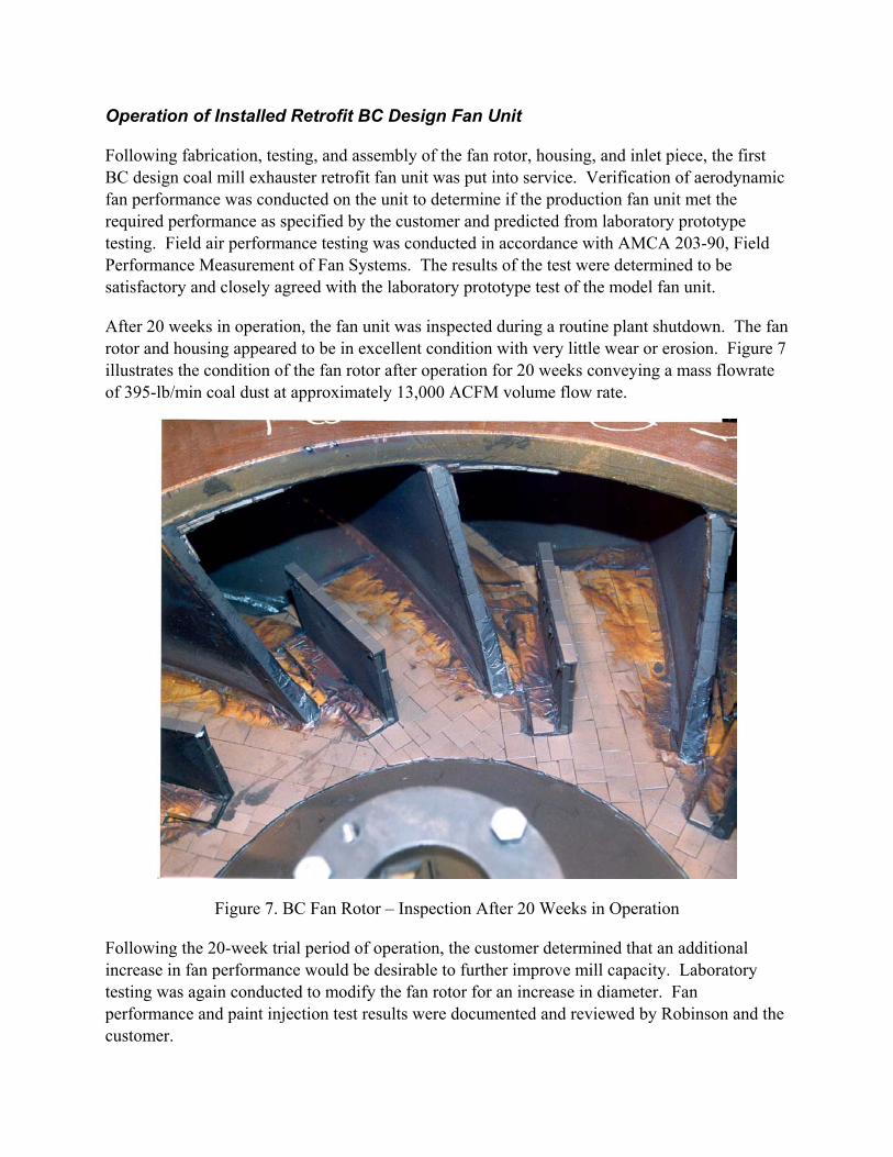
After 20 weeks in operation, the fan unit was inspected during a routine plant shutdown. The fan rotor and housing appeared to be in excellent condition with very little wear or erosion. Figure 7 illustrates the condition of the fan rotor after operation for 20 weeks conveying a mass flowrate of 395-lb/min coal dust at approximately 13,000 ACFM volume flow rate.
Figure 7. BC Fan Rotor – Inspection After 20 Weeks in Operation
Following the 20-week trial period of operation, the customer determined that an additional increase in fan performance would be desirable to further improve mill capacity. Laboratory testing was again conducted to modify the fan rotor for an increase in diameter. Fan performance and paint injection test results were documented and reviewed by Robinson and the customer.

The originally supplied spare fan rotor was modified at the Robinson plant to increase the effective diameter from 64” to 68”. This size was determined to be the maximum possible tip-out diameter based on the customer specified allowable clearance to the fan housing cut-off.
After 50 weeks in operation, the fan unit with the modified rotor was re-inspected to examine the overall mechanical condition of the equipment and to observe the wear on the rotor and other components. During this inspection, some wear was observed on un-lined portions of the rotor back plate. Normal wear was observed on all other areas of the fan rotor and fan housing sides and scroll wrap. Figure 8 illustrates the fan inspection after 50 weeks of operation.
Figure 8. BC Fan Unit – Inspection After 50 Weeks in Operation
Discovery of Blade Erosion Problem on BC Fan Rotor
Following the 50-week inspection on the fan unit, the coal mill was run under normal operating conditions for some additional period of time. During an unscheduled shut down, the exhauster fan unit was inspected as a matter of standard procedure. While the fan rotor was being examined, numerous blades were found to have considerable erosion on the ceramic lining and in some cases the base metal of the blades had completely worn through. The location of wear was consistent on all blades with erosion heaviest near the web plate and approximately 4 to 6 inches along the blade from the outside diameter of the rotor. Figure 9 shows the condition of one severely worn blade / liner during this inspection.
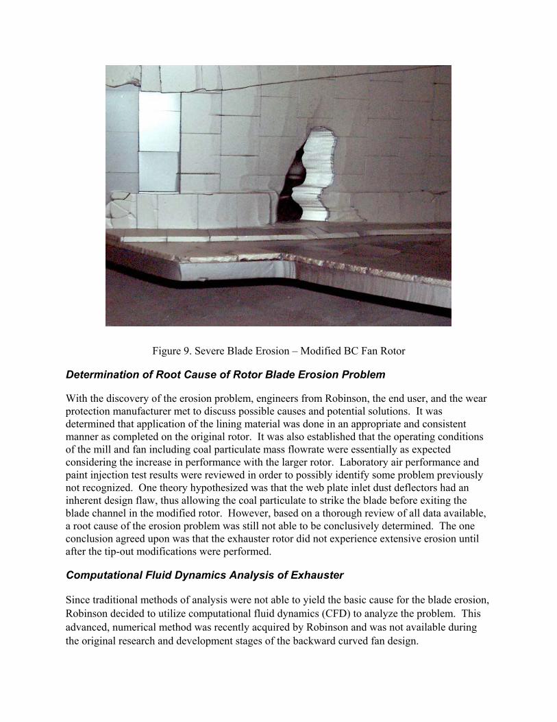
Figure 9. Severe Blade Erosion – Modified BC Fan Rotor
Determination of Root Cause of Rotor Blade Erosion Problem
With the discovery of the erosion problem, engineers from Robinson, the end user, and the wear protection manufacturer met to discuss possible causes and potential solutions. It was determined that application of the lining material was done in an appropriate and consistent manner as completed on the original rotor. It was also established that the operating conditions of the mill and fan including coal particulate mass flowrate were essentially as expected considering the increase in performance with the larger rotor. Laboratory air performance and paint injection test results were reviewed in order to possibly identify some problem previously not recognized. One theory hypothesized was that the web plate inlet dust deflectors had an inherent design flaw, thus allowing the coal particulate to strike the blade before exiting the blade channel in the modified rotor. However, based on a thorough review of all data available, a root cause of the erosion problem was still not able to be conclusively determined. The one conclusion agreed upon was that the exhauster rotor did not experience extensive erosion until after the tip-out modifications were performed.
Computational Fluid Dynamics Analysis of Exhauster
Since traditional methods of analysis were not able to yield the basic cause for the blade erosion, Robinson decided to utilize computational fluid dynamics (CFD) to analyze the problem. This advanced, numerical method was recently acquired by Robinson and was not available during the original research and development stages of the backward curved fan design.
CFD Model Geometry and Solution
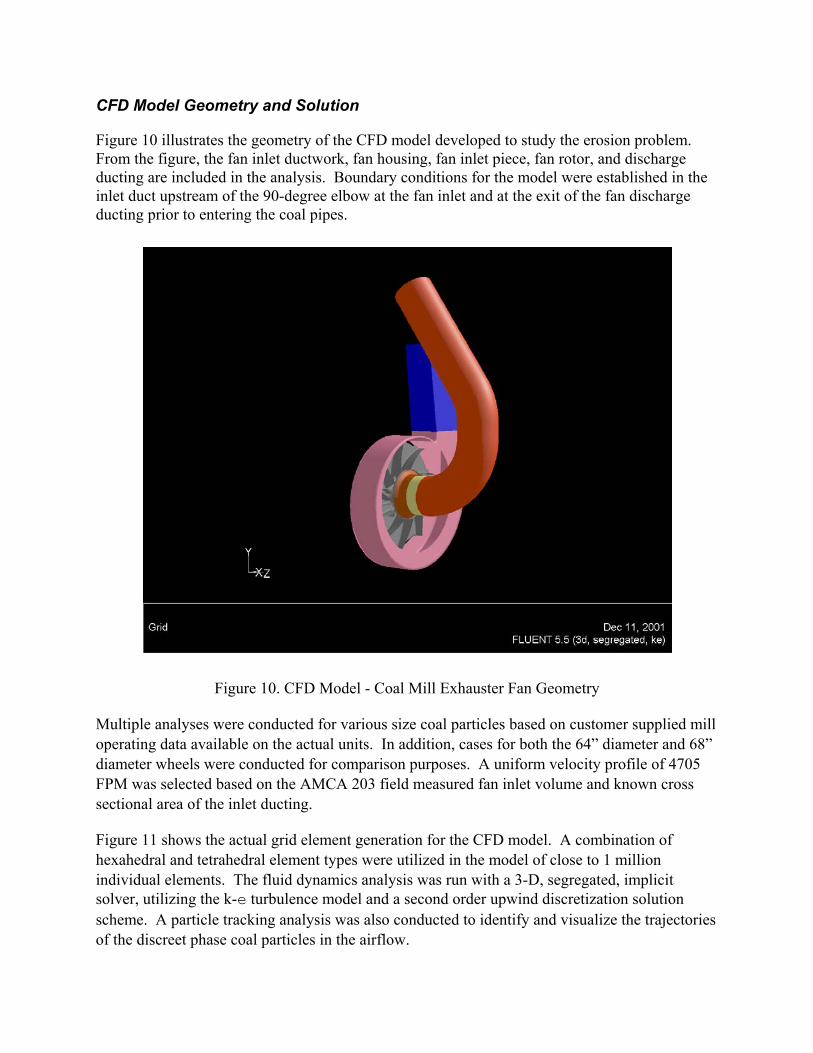
Figure 10 illustrates the geometry of the CFD model developed to study the erosion problem. From the figure, the fan inlet ductwork, fan housing, fan inlet piece, fan rotor, and discharge ducting are included in the analysis. Boundary conditions for the model were established in the inlet duct upstream of the 90-degree elbow at the fan inlet and at the exit of the fan discharge ducting prior to entering the coal pipes.
Figure 10. CFD Model - Coal Mill Exhauster Fan Geometry
Multiple analyses were conducted for various size coal particles based on customer supplied mill operating data available on the actual units. In addition, cases for both the 64” diameter and 68” diameter wheels were conducted for comparison purposes. A uniform velocity profile of 4705 FPM was selected based on the AMCA 203 field measured fan inlet volume and known cross sectional area of the inlet ducting.
Figure 11 shows the actual grid element generation for the CFD model. A combination of hexahedral and tetrahedral element types were utilized in the model of close to 1 million individual elements. The fluid dynamics analysis was run with a 3-D, segregated, implicit solver, utilizing the k-e turbulence model and a second order upwind discretization solution scheme. A particle tracking analysis was also conducted to identify and visualize the trajectories of the discreet phase coal particles in the airflow.
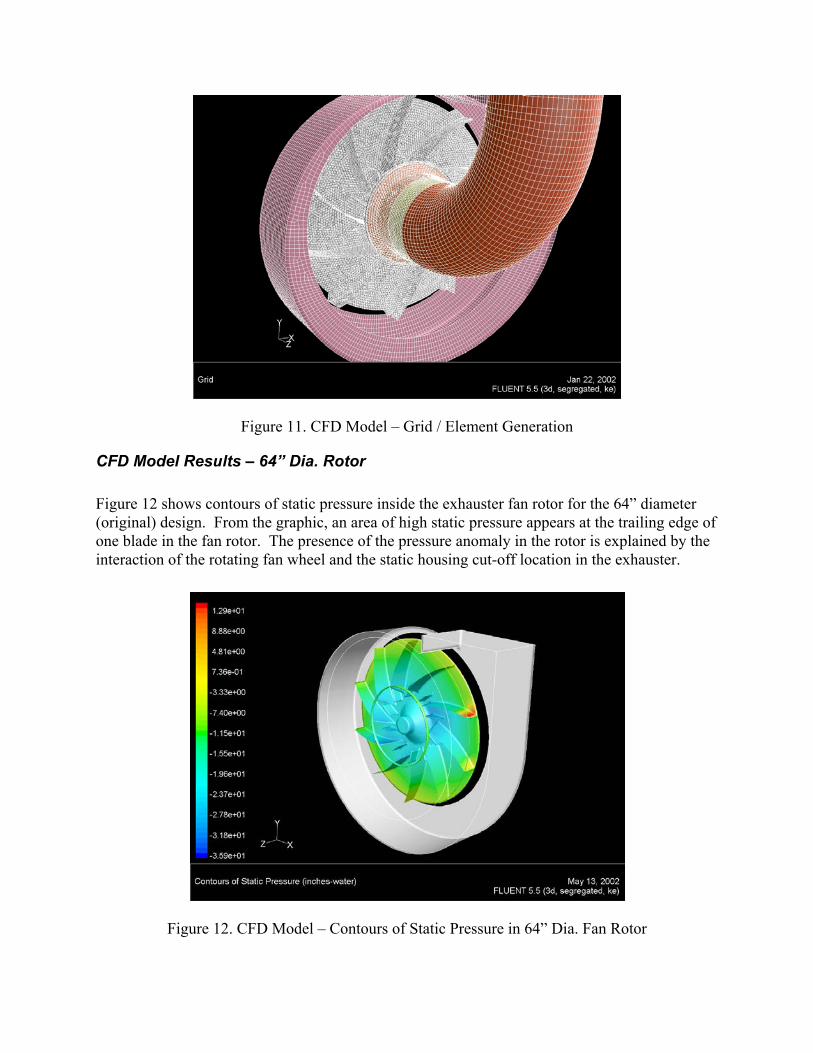
Figure 11. CFD Model – Grid / Element Generation
CFD Model Results – 64” Dia. Rotor
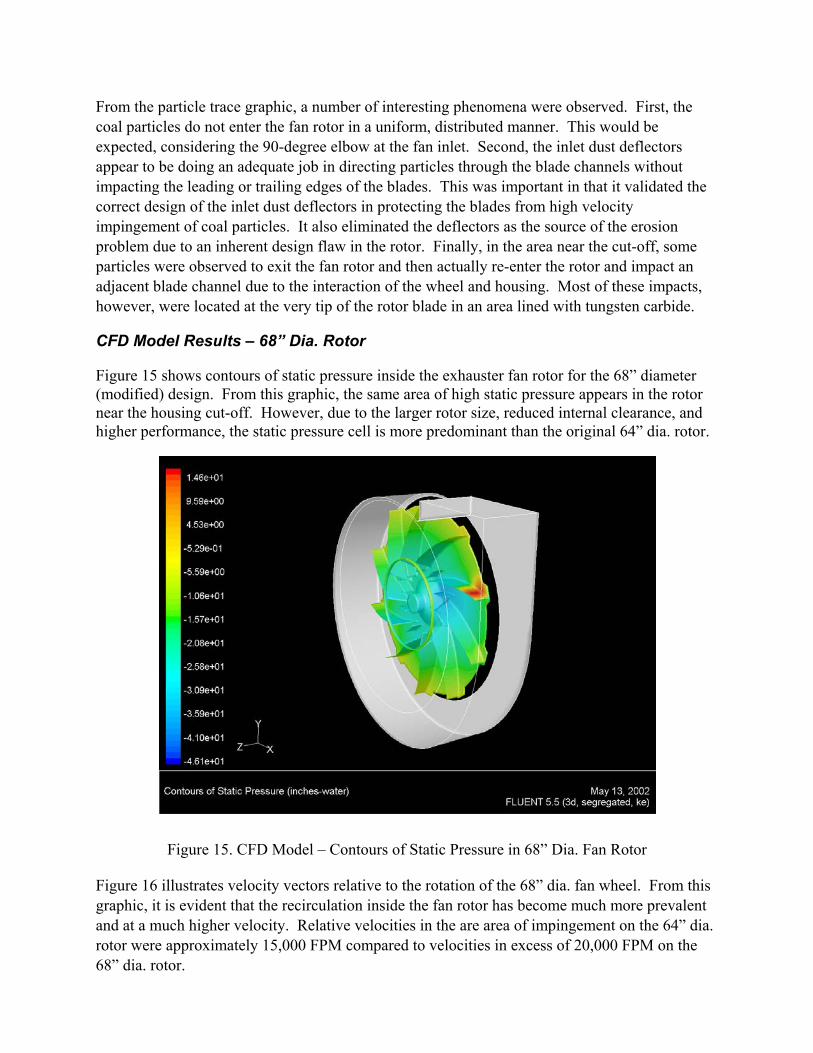
Figure 12 shows contours of static pressure inside the exhauster fan rotor for the 64” diameter (original) design. From the graphic, an area of high static pressure appears at the trailing edge of one blade in the fan rotor. The presence of the pressure anomaly in the rotor is explained by the interaction of the rotating fan wheel and the static housing cut-off location in the exhauster.
Figure 12. CFD Model – Contours of Static Pressure in 64” Dia. Fan Rotor

Figure 13 illustrates velocity vectors relative to fan wheel rotation. From this graphic, low relative velocity recirculation inside the fan rotor may be observed in the same area as the high static pressure cell. The reverse flow was found to be present only in the blade channels adjacent to the fan housing cut-off, meaning each blade would be subjected to this phenomena as it traveled through one revolution. The following graphic is a snapshot of the rotor frozen in time.
Figure 13. CFD Model – Relative Velocity Vectors in 64” Dia. Fan Rotor
Figure 14 shows particle traces of the discrete phase coal particles of 0.0025” diameter as they travel through the fan rotor. The particle size corresponds to 325 mesh and was specified by the customer as the particle size of most interest to analyze. For reference, approximately 80% of the coal particles pass through 200 mesh in this particular application.
Figure 14. CFD Model – 0.0025” Coal Particle Trajectories in 64” Dia. Fan Rotor
From the particle trace graphic, a number of interesting phenomena were observed. First, the coal particles do not enter the fan rotor in a uniform, distributed manner. This would be expected, considering the 90-degree elbow at the fan inlet. Second, the inlet dust deflectors appear to be doing an adequate job in directing particles through the blade channels without impacting the leading or trailing edges of the blades. This was important in that it validated the correct design of the inlet dust deflectors in protecting the blades from high velocity impingement of coal particles. It also eliminated the deflectors as the source of the erosion problem due to an inherent design flaw in the rotor. Finally, in the area near the cut-off, some particles were observed to exit the fan rotor and then actually re-enter the rotor and impact an adjacent blade channel due to the interaction of the wheel and housing. Most of these impacts, however, were located at the very tip of the rotor blade in an area lined with tungsten carbide.
CFD Model Results – 68” Dia. Rotor
Figure 15 shows contours of static pressure inside the exhauster fan rotor for the 68” diameter (modified) design. From this graphic, the same area of high static pressure appears in the rotor near the housing cut-off. However, due to the larger rotor size, reduced internal clearance, and higher performance, the static pressure cell is more predominant than the original 64” dia. rotor.
Figure 15. CFD Model – Contours of Static Pressure in 68” Dia. Fan Rotor
Figure 16 illustrates velocity vectors relative to the rotation of the 68” dia. fan wheel. From this graphic, it is evident that the recirculation inside the fan rotor has become much more prevalent and at a much higher velocity. Relative velocities in the are area of impingement on the 64” dia. rotor were approximately 15,000 FPM compared to velocities in excess of 20,000 FPM on the 68” dia. rotor.
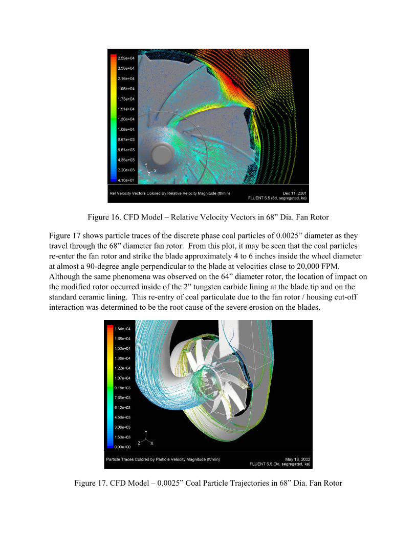
Figure 16. CFD Model – Relative Velocity Vectors in 68” Dia. Fan Rotor
Figure 17 shows particle traces of the discrete phase coal particles of 0.0025” diameter as they travel through the 68” diameter fan rotor. From this plot, it may be seen that the coal particles re-enter the fan rotor and strike the blade approximately 4 to 6 inches inside the wheel diameter at almost a 90-degree angle perpendicular to the blade at velocities close to 20,000 FPM. Although the same phenomena was observed on the 64” diameter rotor, the location of impact on the modified rotor occurred inside of the 2” tungsten carbide lining at the blade tip and on the standard ceramic lining. This re-entry of coal particulate due to the fan rotor / housing cut-off interaction was determined to be the root cause of the severe erosion on the blades.
Figure 17. CFD Model – 0.0025” Coal Particle Trajectories in 68” Dia. Fan Rotor

Recommendations
Once the erosion problem was identified, a number of ideas were presented to reduce or eliminate the effect of the coal particulate impinging on the blades. Potential solutions such as making housing cut-off modifications and installing deflector plates inside the housing were evaluated, but ruled out due to constraints in the fan geometry, adverse affects on fan performance, or cost of implementation. Finally, it was decided to provide the simplest solution of extending the tungsten carbide lining at the tips of the blades down the blade channel an additional 6” to adequately protect the blades from high velocity coal particulate impact.
Conclusion
A new, high efficiency, high capacity backward curved fan was designed to retrofit existing coal mill exhauster units. The new design provided increased performance and improved efficiency, however, a serious erosion problem developed on the fan blades following modification of the rotor to provide the maximum possible performance. When standard analysis methods failed to provide an answer to the problem, computational fluid dynamics (CFD) was utilized to visualize the flow and particle dynamics inside the fan rotor and housing. Based on the results of the CFD analysis, the root cause of the severe blade erosion problem was identified. A cost effective solution was then agreed upon and implemented. The 68” diameter rotor has been in operation without interruption since the modifications were made without any evidence of additional severe erosion on the blades of the coal mill exhauster fan rotor. This analytical study of fan performance and erosion is unique in that this approach had not previously been used to solve an industrial fan related erosion problem of installed equipment at a power generating facility.
Acknowledgments
The author would like to recognize Mr. Samuel B. Toas, Research Engineer, at Robinson Industries, Inc. for development of the computational fluid dynamics models of the subject fan units and subsequent analysis of the aerodynamic and particle tracking results. The author would also like to acknowledge the support of Robinson Industries in the preparation and presentation of this paper at the Welding and Repair Technology for Power Plants, Fifth International EPRI RRAC Conference held on June 26-28, 2002 in Point Clear, Alabama.
References
1. ANSI/AMCA Standard Publication 210-99, Laboratory Methods of Testing Fans for Aerodynamic Performance Rating
2. AMCA Standard Publication 802-92, Industrial Process/Power Generation Fans: Establishing Performance Using Laboratory Models
3. AMCA Standard Publication 203-90, Field Performance Measurement of Fan Systems