
Case-12 Multistage Centrifugal Refrigeration System ...
26
1 Case – 12 Multistage Centrifugal Refrigeration System Halocarbon Refrigerant Copy Right By: Thomas T.S. Wan (温到祥) April 15, 2011 All Rights Reserved Case Background: This case is to show how to achieve the following tasks: (1) To determine the number of stages and how to accommodate a side load for multistage centrifugal compressor. (2) To select a multistage centrifugal compressor to meet the design conditions. (3) To design a refrigeration system for the centrifugal compressor selected and the operating conditions specified. The formula for the estimation of the number of stages for centrifugal shown in the book of Chapter 7 of Engineered Industrial Refrigeration Systems Application is a formula for very rough estimate. The selection method show in this case shall provide a more detail information as how to determine the number of stages. It is important to note that the centrifugal compressor selection should be made and confirmed by the compressor manufacturer. The method shown in this case is just for the purpose for preliminary design of the refrigeration system. The operating conditions for the multistage centrifugal compressor are as the following: Refrigerant: R-22 Refrigeration Capacity (1): 606 TR at ET of –22°F Refrigeration Capacity (2): 216 TR at ET of 14°F Condensing Temperature: 104°F Discharge piping pressure drop: 0.64 Psi Suction piping pressure drop: 0.3 Psi for both evaporators Suction superheat: 6°F for –22°F evaporator, 4°F for 14°F evaporator.
Transcript of Case-12 Multistage Centrifugal Refrigeration System ...

1
Case – 12 Multistage Centrifugal Refrigeration System Halocarbon Refrigerant
Copy Right By: Thomas T.S. Wan (温到祥)
April 15, 2011 All Rights Reserved
Case Background: This case is to show how to achieve the following tasks: (1) To determine the number of stages and how to accommodate a side load for
multistage centrifugal compressor. (2) To select a multistage centrifugal compressor to meet the design conditions. (3) To design a refrigeration system for the centrifugal compressor selected and the
operating conditions specified. The formula for the estimation of the number of stages for centrifugal shown in the book of Chapter 7 of Engineered Industrial Refrigeration Systems Application is a formula for very rough estimate. The selection method show in this case shall provide a more detail information as how to determine the number of stages. It is important to note that the centrifugal compressor selection should be made and confirmed by the compressor manufacturer. The method shown in this case is just for the purpose for preliminary design of the refrigeration system. The operating conditions for the multistage centrifugal compressor are as the following: Refrigerant: R-22
Refrigeration Capacity (1): 606 TR at ET of –22°F Refrigeration Capacity (2): 216 TR at ET of 14°F
Condensing Temperature: 104°F Discharge piping pressure drop: 0.64 Psi Suction piping pressure drop: 0.3 Psi for both evaporators Suction superheat: 6°F for –22°F evaporator, 4°F for 14°F evaporator.
2
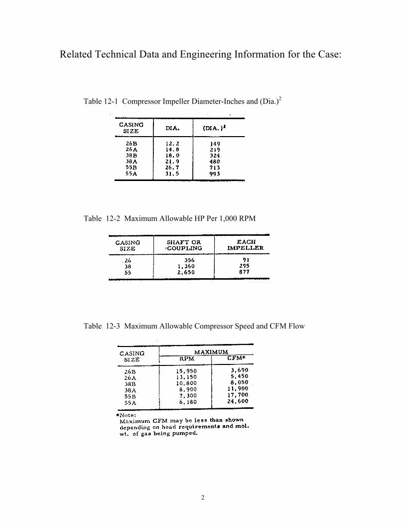
Related Technical Data and Engineering Information for the Case: Table 12-1 Compressor Impeller Diameter-Inches and (Dia.)2
Table 12-2 Maximum Allowable HP Per 1,000 RPM
Table 12-3 Maximum Allowable Compressor Speed and CFM Flow

3
Table 12-4 Approximate Compressor First Critical Speed - RPM
Note: The first number refers to number of stages. The operating compressor speed of the compressor shall not
exceed 80% of the first critical speed. Table 12-5 Maximum Temperature Limitation for Impellers

4
Figure 12-1 Adiabatic Efficiency Map for Multistage Centrifugal Compressor for Halocarbon Refrigerant
Note: Compressor efficiency and part load performance can be improved by changing
the impeller profile design. Ask the compressor manufacturer for a better energy consumption selection for energy conservation application.
5
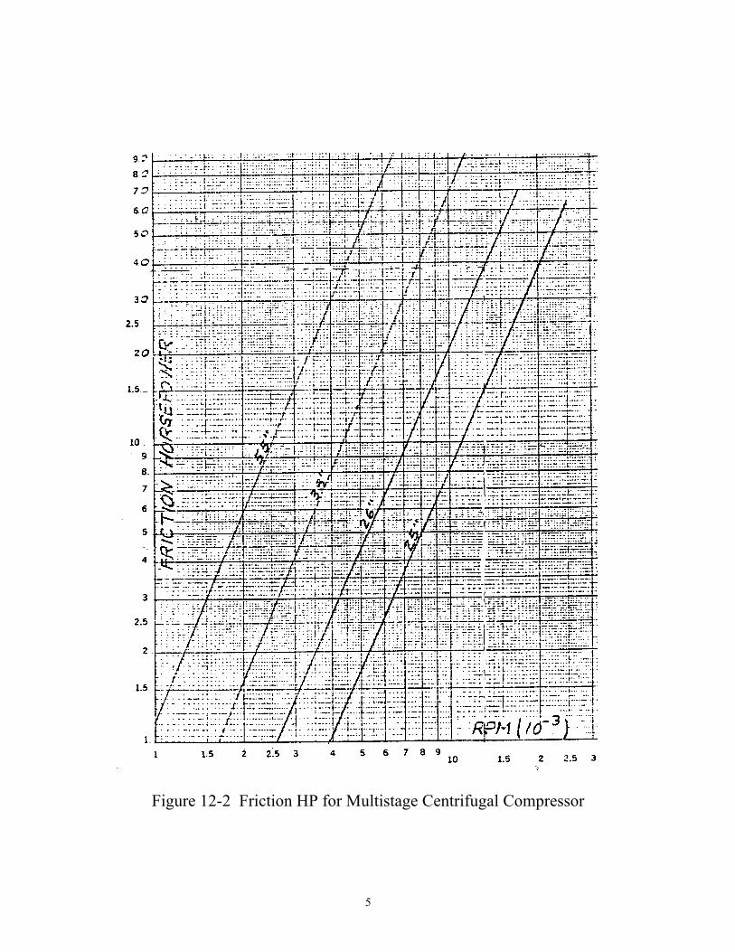
Figure 12-2 Friction HP for Multistage Centrifugal Compressor

6
Cogitation Recap the operating conditions specified for the compressor: Refrigerant: R-22
Refrigeration Capacity (1): 606 TR at ET of –22°F Refrigeration Capacity (2): 216 TR at ET of 14°F
Condensing Temperature: 104°F Discharge piping pressure drop: 0.64 Psi Suction piping pressure drop: 0.3 Psi for both evaporators Suction superheat: 6°F for –22°F evaporator, 4°F for 14°F evaporator. Evaporative Pressure at –22°F = 23.7 Psia Condensing Pressure at 104°F = 222.36 Psia Assuming compressor suction entrance loss = 0.9 Psi Assuming compressor discharge nozzles loss = 8.0 Psi Compressor Suction conditions:
Suction Pressure: 23.7 – 0.3 – 0.9 = 22.5 Psia Suction temperature: -22 + 6 = -16°F
Compressor discharge pressure:
Discharge pressure: 222.36 + 0.64 + 8.0 = 231.0 Psia Notes:
Centrifugal compressor is determined by both the compression head and the actual suction flow of the refrigerant (capacity).
(a) Head determines the requirement of how many stages to be used. (b) Refrigerant Flow (Capacity) determines the compressor size.
Step No. 1 Determine how many stages are needed for the application base on the
lowest compressor suction conditions and the highest compressor discharge pressure:

7
From computer refrigerant property program, all the data at suction conditions can be obtained as the following: Suction conditions: P = Pressure = 22.5 Psia,
t = Temperature = -16°F H1 = Enthalpy = 103.26 Btu/Lb
Vg = Suction Specific Volume = 2.3365 Ft3/Lb Va = Accoustic Velocity = 536.39 Ft/Sec. S = Entropy = 0.2372 Discharge conditions: 231 Psia H2 = 129.80 Compression Head (Had ) = H2 - H1 = 129.80 - 103.26
= 26.54 Btu/Lb or Had = 26.54 x 778 = 20,648 Ft.
Maximum Mach number for the application is 1.3 Ts Mo = ------ Va Mo : Mach number Ts : Impeller Tip Speed, Ft/Sec Va : Accoustic Velocity. Ft/Sec. Reasonable Max. impeller Tip Speed = Mo x Va = 1.25 x 536.39 = 670 Ft/Sec. Tip Speed Formula: 32.2 x Had Ts = ------------------- N x µad Assume µad = 0.51 32.2 x 20,648 670 = -------------------- N x 0.51

8
From the above formula: Number of stages, N = 2.904 Say 3-stage Ts = 659.2 Ft/Sec.
Mo = 1.229 It is preferred that the Mach number to be around 1.1 unless it is under tight cost consideration. Therefore, try to use a 4-stage compressor instead of 3-stage 32.2 x 20,648 Ts = ---------------------- 4 x 0.51 = 570.9 Ft/Sec 570.9 Mo = --------------- = 1.064 536.39 From the Adiabatic Head Coefficient Table, Figure 12-1, the Maximum value of µad for Mach number up to 1.10 is 0.48, therefore the tip speed should be corrected as the following: 32.2 x 20,648 Ts = ---------------------- 4 x 0.48 = 588.46 Ft/Sec 588.46 Mo = -------------- = 1.098 Ok! 536.39 4-stage compressor is used. Step No. 2 Determine the inter-stage pressures of the compressor.
Compression Head = H2 - H1 = 129.80 - 103.26 = 26.54 Btu/Lb

9
26.54 Each impeller is to handle = ------------- = 6.635 Btu/Lb 4 Stages Standard arrangement for the compressor is all the wheels are having the same diameter; each impeller handles equal head, not equal compression ratio as shown in Figure 12-3.
Figure 12-3 Enthalpy Difference Between Impellers At compressor suction the suction pressure is 22.5 Psia, the suction temperature is -16°F, from refrigerant R-22 property, the enthalpy at suction condition H1 is 103.26 Btu/Lb and the entropy is 0.2372. See Figure 12-4, the ΔH for each stage is 6.635, therefore, the enthalpy for the first impeller discharge is 103.26 + 6.635 = 109.90; the enthalpy value for each impeller discharge can be obtained by using the same method as the following: Enthalpy for 1st stage impeller: 109.90 Enthalpy for 2nd stage impeller: 116.53 Enthalpy for 3rd stage impeller: 123.17

10
Figure 12-4 The Enthaply Points Between Impeller Discharge See Figure 12-5, under adiabatic compression function, the S = 0.2372 is constant, the interstage pressure between stage can be obtain by using various enthalpy points at constant entropy of 0.2372.
Figure 12-5 Interstage Pressure Between Stages

11
Suction pressure for 2nd stage impeller: 43.15 Psia Suction pressure for 3rd stage impeller: 77.28 Psia Suction pressure for 4th stage impeller: 136.55 Psia Step No. 3 – To determine where the side load connection should be located for the ET of
14°F No.2 refrigeration load. The evaporative pressure for the 14°F refrigeration load is 51.37 Psia.
Therefore, side load connection for the No. 2 refrigeration should be at the second stage inlet where the impeller inlet pressure is 43.15 Psia.
The total pressure difference for piping loss and the nozzle connection
pressure drop is 51.37 – 43.15 = 8.22 Psi. Pressure drop allocations: External piping PD = 0.3 Psi Control Valves = 4 Psi PD available for Side Connection = 3.92 Psi Step No. 4 - To format the P-H diagram in accordance with the design concept and select
the number of stage intercooling for the compressor: Assume the system is a close couple refrigeration system. The evaporators are close
to each other in the same engine room. Therefore, flash intercoolers are to be used. 4-Stage compressor, maximum 3 intercooling are allowed. 2 stages flash
intercooling are used for the system for this case instead of 3-stage intercooling because the suction of the side load 216 TR at ET of 14°F already connected to the 2nd stage inlet.
Figure 12-6 is the P-H diagram which reflects all the design approaches with 2-stage
flash intercooling. The evaporative temperature for intercooler is fixed to allow approximately 5 Psi
pressure difference between the saturated evaporative pressure of the intercooler and the interstage suction pressure of the impeller; this 5 Psi pressure difference allowed is for external piping and control valve pressure drops for the intercooler.
All the enthalpy points, temperatures and pressures shown on the Figure 12-6 are
obtained from the R-22 refrigerant property software.
12
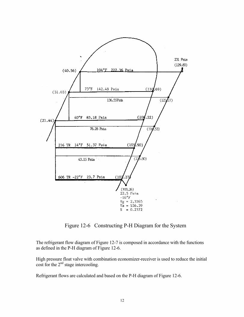
Figure 12-6 Constructing P-H Diagram for the System The refrigerant flow diagram of Figure 12-7 is composed in accordance with the functions as defined in the P-H diagram of Figure 12-6. High pressure float valve with combination economizer-receiver is used to reduce the initial cost for the 2nd stage intercooling. Refrigerant flows are calculated and based on the P-H diagram of Figure 12-6.

13
Figure 12-7 Composed Refrigerant Flow Diagram for the System

14
Step No. 5 – Calculate the refrigerant flows of the system. Compressor main suction flow, Refrigeration Load No.1: 200 ---------------------- x 606 = 1,499.44 Lbs/Min. 102.27 – 21.44 Refrigerant flow for Load No.2: 200 ---------------------- x 216 = 511.48 Lbs./Min. 105.90 – 21.44 Total refrigerant flow for Loads No.1 and No.2: = 1,499.44 + 511.48 = 2,010.92 Lbs./Min. Flash gas to the compressor 2nd stage inlet: 108.22 – 21.44 = 2,010.92 x [ ------------------------- - 1 ] 108.22 – 31.03 = 249.83 Lbs./Min. Liquid leaving 1st stage economizer: = 2,010.92 + 249.83 = 2,260.75 Lbs./Min. Flash gas to the compressor 1st impeller inlet: 110.69 – 31.03 = 2,260.75 x [ ------------------------- - 1 ] 110.69 – 40.56 = 307.21 Lbs./Min. Step No. 6 – Determine Compressor suction ACFM:

15
Compressor suction ACFM flow: = Suction flow (Lbs./Min.) x Vg = 1,499.44 x 2.3365 = 3,503.44 CFM
Figure 12-8 System P-H Diagram

16
Figure 12-9 System Refrigerant Flow Diagram

17
Step No. 7 – Compressor Calculation: Capacity Factor = Q/ND3 7.54 x CFM Q/ND3 = ------------------- Ts x D2 Try M426A compressor. (4-stage, 26A casing) From the compressor data sheet Table 12-1. D² = 219 Ts = 588.46 ft/sec. CFM = 3,503.44 7.54 x 3,503.44 Q/ND3 = ---------------------- = 0.205 Ok. 588.46 x 219 Therefore, M426A compressor is selected . Notes:
(a) The compressor size is determined by the suction ACFM and the tip speed of the compressor.
(b) Overall compression ratio of the machine must be used for determining the
efficiency of the compressor. Wheel by wheel analysis method is not allowed.
(c) The capacity limitation must be check if the capacity factor Q/ND3 is over
0.20.
(d) The efficiency of the compressor is generally fixed by the size of the first stage impeller.

18
Step No. 8 – Determine the compressor efficiency: Compression Ratio: P2 231.0 CR = ------- = ----------- = 10.27 P1 22.5 This is Halocarbon application, therefore, Adiabatic Rating curve should be used. From the compressor performance map Figure 12-1, Capacity Factor Q/ND3 = 0.205 & CR = 10.27 ηad = 73.0% Check capacity limitation, maximum Q/ND3 allowed is 0.215 for Mach number 1.1,
therefore, the selection of M425A is Ok. The efficiency multipliers: Compressor size: 1.0 Mach Number: 1.0 Corrected ηad = 73.0% x 1.0 x 1.0 = 73.0% Step No. 9 - Horse Power calculation: W x Had GHP = -------------------- 33000 x ηad (1499.44 x 20648) + (511.48 x 15486) + (249.83 x 10324) + (307.21 x 5162) = ---------------------------------------------------------------- 33000 x 0.73 = 1,786.9 HP Step No. 10 - Determine the Compressor Speed: 229 x Ts Rpm = ------------------- D Ts = 588.46 ft/sec.
19
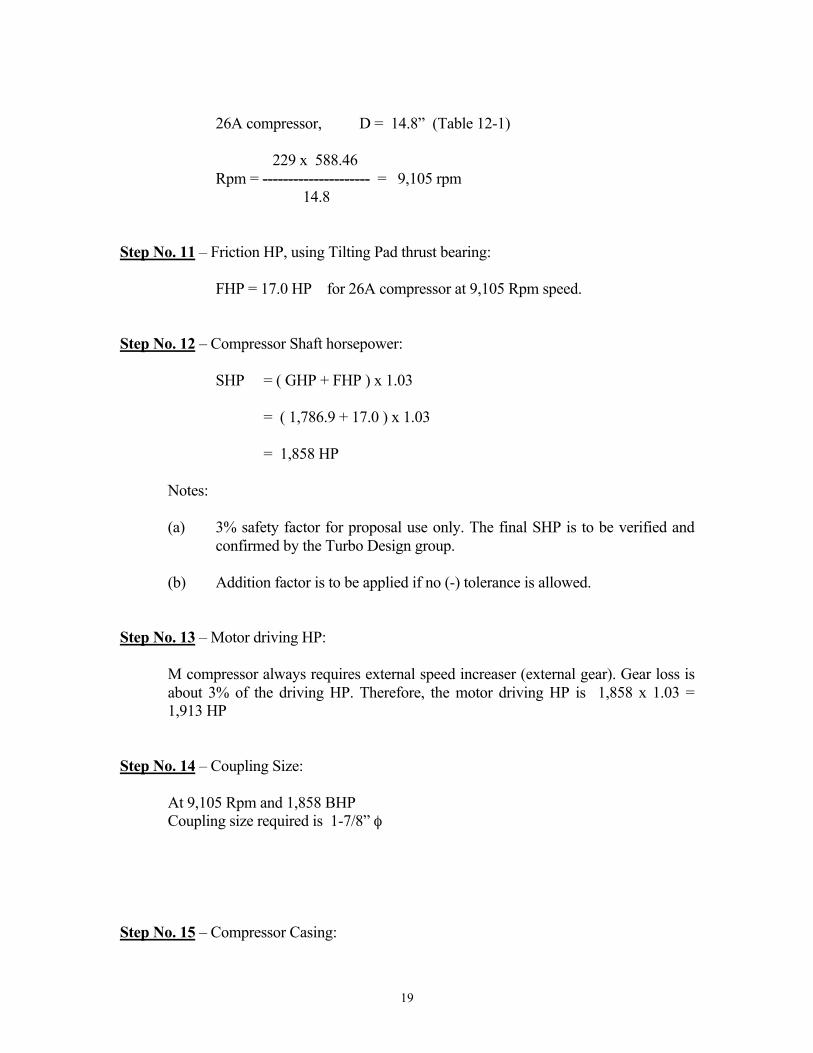
26A compressor, D = 14.8” (Table 12-1) 229 x 588.46 Rpm = --------------------- = 9,105 rpm 14.8 Step No. 11 – Friction HP, using Tilting Pad thrust bearing: FHP = 17.0 HP for 26A compressor at 9,105 Rpm speed. Step No. 12 – Compressor Shaft horsepower: SHP = ( GHP + FHP ) x 1.03 = ( 1,786.9 + 17.0 ) x 1.03 = 1,858 HP Notes:
(a) 3% safety factor for proposal use only. The final SHP is to be verified and confirmed by the Turbo Design group.
(b) Addition factor is to be applied if no (-) tolerance is allowed.
Step No. 13 – Motor driving HP: M compressor always requires external speed increaser (external gear). Gear loss is
about 3% of the driving HP. Therefore, the motor driving HP is 1,858 x 1.03 = 1,913 HP
Step No. 14 – Coupling Size: At 9,105 Rpm and 1,858 BHP Coupling size required is 1-7/8” φ Step No. 15 – Compressor Casing:

20
Compressor maximum discharge pressure is 209 Psig. Therefore, Cast Iron casing is
satisfactory with 300 Psig DWP. Step No. 16 – Coupling Maximum HP: 9,105 Coupling Max. HP = 356 x --------------- = 3,241 HP Ok. 1,000 Step No. 17 – Impeller Fastening: 9,105 Impeller Fastening HP = 120 x --------------- = 1,092.6 HP 1,000 The 4th impeller carry highest BHP: 2,567.96 x 5,162 = ----------------------------- 550.26 BHP < 1,092.6 HP Ok. 33,000 x 0.73 Step No. 18 – Complete the P-H Diagram. See the attached P-H with all the points calculated.

21
Figure 12-10 Final System P-H Diagram Step No. 19 – Compressor Discharge Temperature: Compressor discharge temperature is calculated at 212.5°F Compressor discharge with PRV closed = -16 +{212.5 – (-16)} x 1.3 = 279.75°F ≅ 280°F

22
Step No. 20 – Oil Cooler: Oil cooler = FHP + F x (Tdisch. – 275) TDisch. = 280°F Oil Cooling = 17 + 0.08 x (280 – 275) = 17.4 HP Therefore, Oil cooling = 18 FHP Step No. 21 – Impeller Material: Ts = 588.46 ft/sec. Maximum temperature for Aluminum impeller allowed is 388°F from Data Sheet. Discharge temperature is 280 < Max. temperature 388°F allowed. Therefore, all Aluminum wheels are Ok. Step No. 22 – Last Wheel Q/ND3: Last wheel flow = 2,567.96 Lbs/Min Last wheel inlet Vg = 0.5014 Last wheel ACFM = 2,567.96 x 0.5014 = 1,287.5 CFM Ts = 588.46 ft/sec. 7.54 x 1,287.5 Q/ND3 = ---------------------- = 0.075 588.46 x 219 Last wheel Q/ND3 = 0.075 > Minimum 0.02 Limit, Ok Step No. 23 – Check Critical Speed: See Table 12-4, the first critical speed of all Aluminum wheel of M426A
compressor is 18,400 RPM. The compressor speed is 9,105 RPM. The critical speed is above the operation speed and it should be at least 20% above the operating speed.
1.2 x 9,105 = 10,926 RPM, the critical speed > 10,926 rpm, above 20% of the
operating speed. Ok.
23
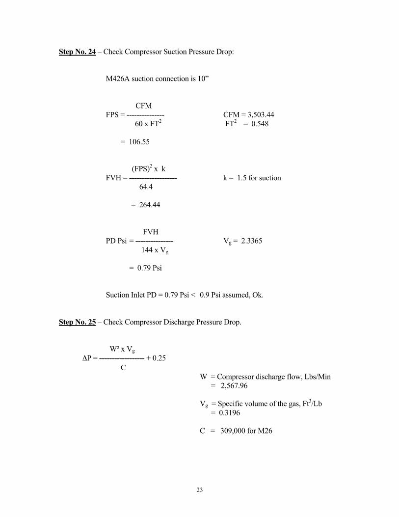
Step No. 24 – Check Compressor Suction Pressure Drop: M426A suction connection is 10” CFM FPS = --------------- CFM = 3,503.44 60 x FT2 FT2 = 0.548 = 106.55 (FPS)2 x k FVH = ------------------- k = 1.5 for suction 64.4 = 264.44 FVH PD Psi = --------------- Vg = 2.3365 144 x Vg = 0.79 Psi Suction Inlet PD = 0.79 Psi < 0.9 Psi assumed, Ok. Step No. 25 – Check Compressor Discharge Pressure Drop. W² x Vg ΔP = ------------------ + 0.25 C W = Compressor discharge flow, Lbs/Min = 2,567.96 Vg = Specific volume of the gas, Ft3/Lb = 0.3196 C = 309,000 for M26

24
(2,567.96)² x 0.3196 ΔP = ------------------------------- + 0.25 309,000 = 7.07 Psi Discharge PD = 7.07 Psi < 8.0 Psi assumed. Ok. Step No. 25 – Check Side Load Connection: The side load of 14°F is the largest flow of all the side connections. Flow = 511.48 Lbs/Min. Vg = 1.047, CFM = 536 Try two (2) standard size side connection 3”φ, FT2 = 0.0513 x 2 = 0.1026 CFM FPS = --------------- CFM = 536 cfm 60 x FT2 FT2 = 0.1026 = 87.1 Inlet velocity = 87.1 FPS<1/3(Ts) = (1/3) x (588.46) = 196 fps, Ok. (FPS)2 x k FVH = ------------------- k = 3.0 for suction 64.4 = 353.4 FVH PD Psi = --------------- Vg = 1.047 144 x Vg = 2.34 Psi Side load connection PD = 2.34 Psi < 3.92 Psi allowed. Ok.
25
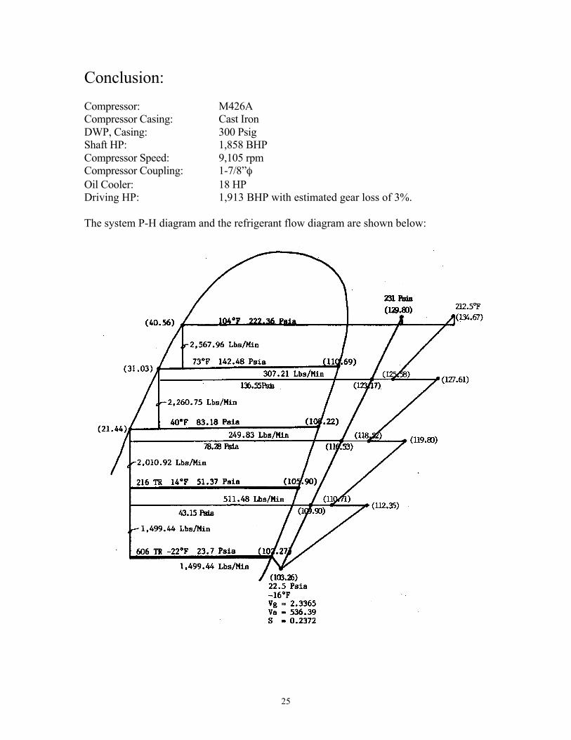
Conclusion: Compressor: M426A Compressor Casing: Cast Iron DWP, Casing: 300 Psig Shaft HP: 1,858 BHP Compressor Speed: 9,105 rpm Compressor Coupling: 1-7/8”φ Oil Cooler: 18 HP Driving HP: 1,913 BHP with estimated gear loss of 3%. The system P-H diagram and the refrigerant flow diagram are shown below:

26