CARMAN SCANER
94
1 Carmanscan Lite User's Guide Ver. 080501
-
Upload
bladimir-guacha -
Category
Documents
-
view
64 -
download
0
Transcript of CARMAN SCANER

1
Carmanscan Lite User's Guide
Ver. 080501
2
Carmanscan Lite User's Guide
Content
Safety Warnings……………………………………..…………………......5
CHAPTER 1 General Descriptions………………………………………6 1. Product Features……………………………………………………………………..6 2. Product Specifications………………………………………………………………7 3. Rechargeable Battery …………………………………………..…………..……….8 4. List of Components…………………………………………………………………9 5. Photos and Descriptions of Components ……………………………………..12 6. Power Supply ……………………………………………………………………….24
CHAPTER 2 Menu Configuration.……………………………………...25 1. Before Getting Started……………………………………………………………..25 2. Menu Description……………………………………………………………………26
CHAPTER 3 System Setup………………………….............................27 1. System Configuration………………………………………………………………27 2. Data Setup …………….……………………………………………………………..29 3. Keypad Test…………………………………………………………………………..32 4. Contrast Adjust Screen…………………................................……………….…33 5. Battery Status……………………..…………………………………………………34
CHAPTER 4 Screen Capture View …….……………………………35 1. Screen Capture………………………………………………………………………35 2. Screen Capture View……………………………………………………………….36
CHAPTER 5 S/W Download……………………………………………..37CHAPTER 6 Selecting Diagnosis Menu………………………………….38 1. Connecting Self Diagnosis Connector and Selecting Diagnosis Program…………………………………………………………………………….38 2. Diagnosing Korean Vehicles..……………………………........…………………40 3. Diagnosing Japanese Vehicles (General)……………………………………....41 4. Diagnosing Japanese Vehicles (AUTO SEARCHING MODE)………….…….43
3
Carmanscan Lite User's Guide
Comment
5. Diagnosing Japanese Vehicles (GENERAL MODE)………………….......…45 6. Diagnosing European Vehicles…………………………………………………47
CHAPTER 7 Vehicle Diagnosis…………………………………………49 1. Diagnostic Trouble Codes…………………………………………………………49 2. Current Data…………………………………………………………………..……52 3. Combination Display………………………………………………………………58 4. Flight Record………………………………………………………………………60 5. Actuation Test………………………………………………………………………62
CHAPTER 8 OBD-II Selecting Menu……………………………………64 1. OBD-II Overview……………………………………………………………………64 2.Connecting Self Diagnosis Connector and Selecting Diagnosis Program……………………………………………………………………………65
CHAPTER 9 OBD-II Vehicle Diagnosis………………………………69 1. Readiness Test ………………………………………………………………….…69 2. Current Data Display..………………………………………………………………71 3. Diagnostic Trouble Codes…………………………………………………………73 4. Freeze Frame Data…………………………………………………………………75 5. EDP: Expanded Diagnostic Protocol………………………………….………...76 6. O2 Test Results ……………………………………………………………………79 7. Monitoring Test Results……………………………………………………………81 8. Combination Display………………………………………………………………83 9. ECU Information……………………………………………………………………8510. Pending Diagnostic Trouble Codes……………………………………………86
CHAPTER 10 Flight Record Review……………………………….......88
4
Carmanscan Lite User's Guide
WARNING
COPYRIGHT No part of this manual may be reproduced, stored in a retrieval system or transmitted, in any form or by any means, electronic, mechanical, photocopying, recording, or otherwise, without the prior written permission of NEXTECH.
DISCLAIMER All information, illustrations, and specifications contained in this technical instruction manual are based on the latest information available at the time of publication. The right is reserved to make changes at any time without obligation to notify any person or organization of such revisions or changes. Further, NEXTECH shall not be liable for errors contained herein or for incidental or consequential damages (including lost profits) in connection with the furnishing, performance or use of this material.
© 2008 NEXTECH Corporation. All rights reserved.
5
Carmanscan Lite User's Guide
Safety Warnings
Safety Instruction
Safety Warning Carmanscan Lite mentioned in this User's Guide is designed for those who have basic qualifications for using this system. For safe and effective use, follow the safety instructions described in this User's Guide. The followings are general instructions that you must remember when you use the system. Do not drop the Carmanscan Lite. Always use Carmanscan Lite in the rubber Shroud to
protect it. Do not place Carmanscan Lite on the power distributor.
Although Carmanscan Lite was designed to be free from electromagnetic interference, but excessive electromagnetic interference may damage the system.
Excessive surge or electric shock fed by power cable may
damage the power supply system of Carmanscan Lite. Do not use
Carmanscan Lite in an environment where power supply is unstable.
The AC/DC adapter was designed for 12V DC. Use AC/DC adapter with rated voltage.
6
Carmanscan Lite User's Guide
Chapter 1 : General Descriptions
1. Product Features
Carmanscan Lite can check vehicle ECU information and error status through OBD-I, OBD-II, and CAN communication. You can connect Carmanscan Lite vehicle diagnosis connector with a diagnosis cable, check if any of engine, automatic transmission, ABS, air bag, power steering, and other devices has an error, view Current Data, and use actuator drive features. Carmanscan Lite has the following features:
Diagnoses Korean, Japanese, European vehicles▶ . - OBD-I ,OBD-II compatible protocol: OBD-II (ISO 9141-2), OBD-II (SAE-J1850),
KWP-2000, CAN and SAE J1587. Supports trouble diagnosis and service date search. ▶ - You can diagnose using the sensors and switches installed in the car, and save
and reload the sensor data. Supports actuator auto inspection.▶ - This uses the scanner run/stop the actuator and switches by force to check if the
device is normal. You can view the following test results:▶ - O2 Sensor Test and Monitoring Test - Freeze frame data You can save data or upgrade the diagnosis program by connecting to a ▶ PC. You can change the sound effects and display unit of the scanner.▶ Provides LCD brightness adjustment and keypad testin▶ g. With the built▶ -in battery, you can perform diagnosis without power supply. Supports TPMS communication (optional)▶
7
Carmanscan Lite User's Guide
Chapter 1 : General Descriptions
2. Product Specifications
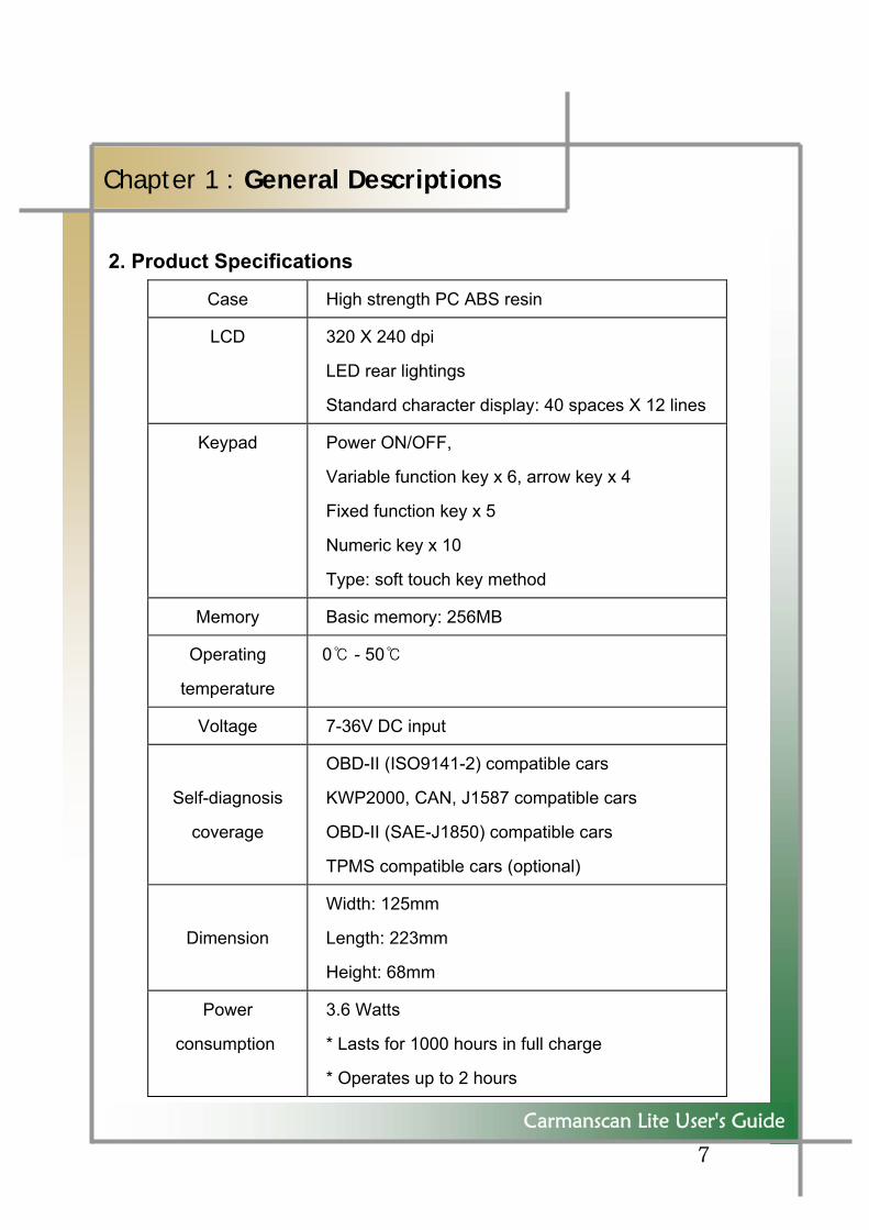
Case High strength PC ABS resin
LCD 320 X 240 dpi
LED rear lightings
Standard character display: 40 spaces X 12 lines
Keypad Power ON/OFF,
Variable function key x 6, arrow key x 4
Fixed function key x 5
Numeric key x 10
Type: soft touch key method
Memory Basic memory: 256MB
Operating
temperature
0 ℃ - 50℃
Voltage 7-36V DC input
Self-diagnosis
coverage
OBD-II (ISO9141-2) compatible cars
KWP2000, CAN, J1587 compatible cars
OBD-II (SAE-J1850) compatible cars
TPMS compatible cars (optional)
Dimension
Width: 125mm
Length: 223mm
Height: 68mm
Power
consumption
3.6 Watts
* Lasts for 1000 hours in full charge
* Operates up to 2 hours
8
Carmanscan Lite User's Guide
Chapter 1 : General Descriptions
3. Rechargeable Battery
The rechargeable battery pack has the following features: - Voltage of the battery pack gradually decreases even when the system does
not run. - Before you use the product for the first time, be sure to fully charge the
battery. Always use the rechargeable batter pack provided by
Nextech. - Using a 3rd party product may cause explosion. (7.4V 2200mAh lithium ion battery pack)
Do not heat the battery pack. - It may cause explosion. Do not short the battery pack terminal. - It may cause explosion. Do not place the battery pack on or near hot material over
60ºC. - It may cause explosion. Keep the battery pack away from touch of children or
animal. - It may cause fire or injury.
To prevent the battery pack from being discharged, always
Connect the power before using the system. Because of Discharged battery pack you may lose your screen captures, flight record data, etc.
9
Carmanscan Lite User's Guide
Chapter 1 : General Descriptions
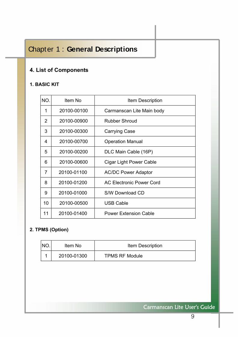
4. List of Components 1. BASIC KIT
NO. Item No Item Description
1 20100-00100 Carmanscan Lite Main body
2 20100-00900 Rubber Shroud
3 20100-00300 Carrying Case
4 20100-00700 Operation Manual
5 20100-00200 DLC Main Cable (16P)
6 20100-00600 Cigar Light Power Cable
7 20100-01100 AC/DC Power Adaptor
8 20100-01200 AC Electronic Power Cord
9 20100-01000 S/W Download CD
10 20100-00500 USB Cable
11 20100-01400 Power Extension Cable
2. TPMS (Option)
NO. Item No Item Description
1 20100-01300 TPMS RF Module
10
-
Carmanscan Lite User's Guide
Chapter 1 : General Descriptions
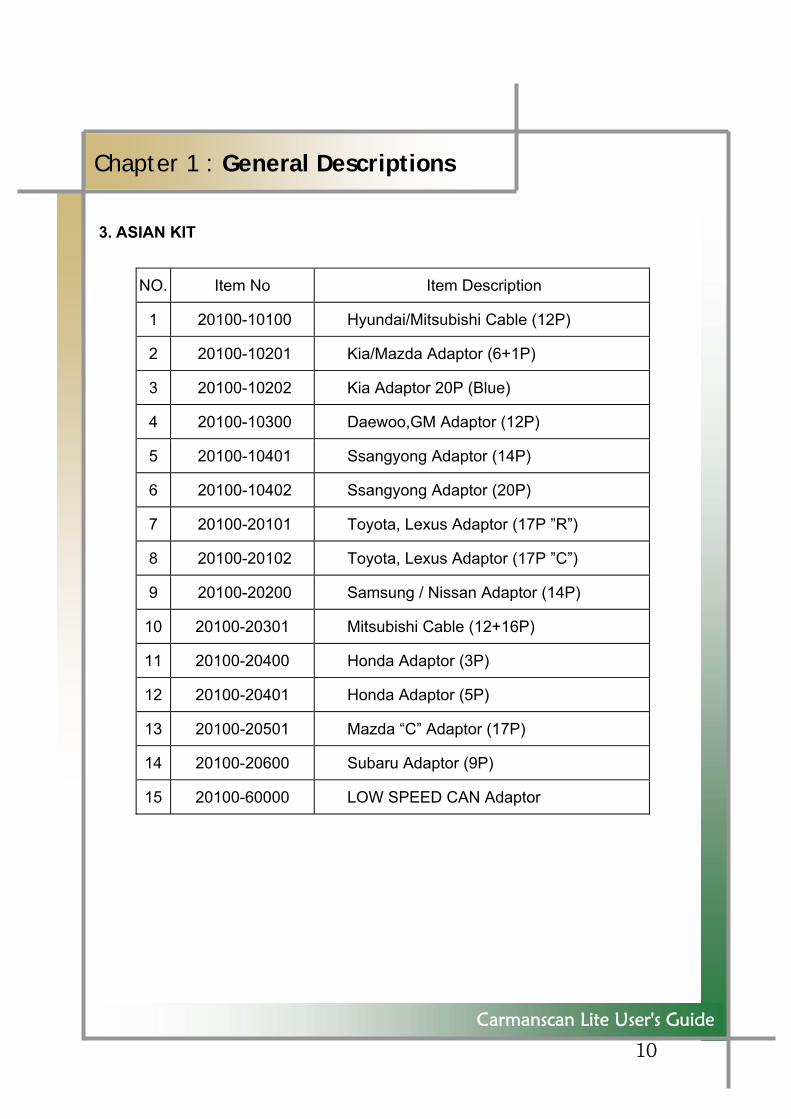
3. ASIAN KIT
NO. Item No Item Description
1 20100-10100 Hyundai/Mitsubishi Cable (12P)
2 20100-10201 Kia/Mazda Adaptor (6+1P)
3 20100-10202 Kia Adaptor 20P (Blue)
4 20100-10300 Daewoo,GM Adaptor (12P)
5 20100-10401 Ssangyong Adaptor (14P)
6 20100-10402 Ssangyong Adaptor (20P)
7 20100-20101 Toyota, Lexus Adaptor (17P ”R”)
8 20100-20102 Toyota, Lexus Adaptor (17P ”C”)
9 20100-20200 Samsung / Nissan Adaptor (14P)
10 20100-20301 Mitsubishi Cable (12+16P)
11 20100-20400 Honda Adaptor (3P)
12 20100-20401 Honda Adaptor (5P)
13 20100-20501 Mazda “C” Adaptor (17P)
14 20100-20600 Subaru Adaptor (9P)
15 20100-60000 LOW SPEED CAN Adaptor
11
Carmanscan Lite User's Guide
Chapter 1 : General Descriptions
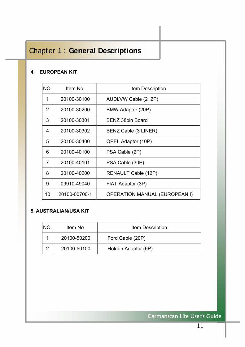
4. EUROPEAN KIT
NO. Item No Item Description
1 20100-30100 AUDI/VW Cable (2+2P)
2 20100-30200 BMW Adaptor (20P)
3 20100-30301 BENZ 38pin Board
4 20100-30302 BENZ Cable (3 LINER)
5 20100-30400 OPEL Adaptor (10P)
6 20100-40100 PSA Cable (2P)
7 20100-40101 PSA Cable (30P)
8 20100-40200 RENAULT Cable (12P)
9 09910-49040 FIAT Adaptor (3P)
10 20100-00700-1 OPERATION MANUAL (EUROPEAN I)
5. AUSTRALIAN/USA KIT
NO. Item No Item Description
1 20100-50200 Ford Cable (20P)
2 20100-50100 Holden Adaptor (6P)
12
Carmanscan Lite User's Guide
Chapter 1 : General Descriptions
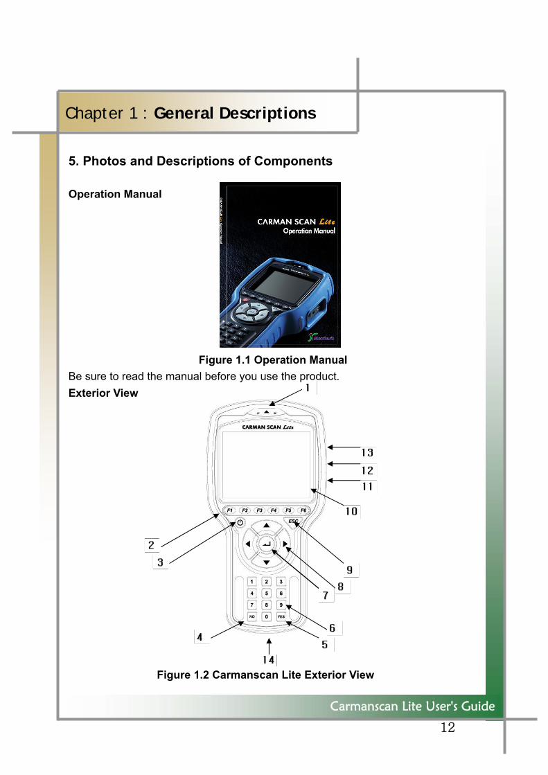
5. Photos and Descriptions of Components Operation Manual Figure 1.1 Operation Manual Be sure to read the manual before you use the product. Exterior View Figure 1.2 Carmanscan Lite Exterior View
13
Carmanscan Lite User's Guide
Chapter 1 : General Descriptions
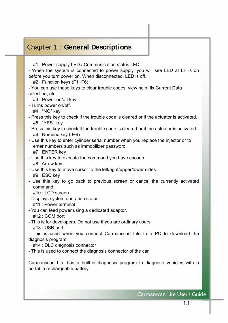
#1 : Power supply LED / Communication status LED
- When the system is connected to power supply, you will see LED at LF is on before you turn power on. When disconnected, LED is off.
#2 : Function keys (F1~F6) - You can use these keys to clear trouble codes, view help, fix Current Data selection, etc.
#3 : Power on/off key - Turns power on/off.
#4 : “NO” key - Press this key to check if the trouble code is cleared or if the actuator is activated.
#5 : “YES” key - Press this key to check if the trouble code is cleared or if the actuator is activated.
#6 : Numeric key (0~9) - Use this key to enter cylinder serial number when you replace the injector or to
enter numbers such as immobilizer password. #7 : ENTER key
- Use this key to execute the command you have chosen. #8 : Arrow key
- Use this key to move cursor to the left/right/upper/lower sides. #9 : ESC key
- Use this key to go back to previous screen or cancel the currently activated command. #10 : LCD screen
- Displays system operation status. #11 : Power terminal
- You can feed power using a dedicated adaptor. #12 : COM port
- This is for developers. Do not use if you are ordinary users. #13 : USB port
- This is used when you connect Carmanscan Lite to a PC to download the diagnosis program.
#14 : DLC diagnosis connector - This is used to connect the diagnosis connector of the car. Carmanscan Lite has a built-in diagnosis program to diagnose vehicles with a portable rechargeable battery.
14
Carmanscan Lite User's Guide
Chapter 1 : General Descriptions
LCD Screen
Item 10 : LCD screen has 320 by 240 resolution with an EL Black LCD
Note : The item numbers refer to Figure 1.2 Scan Tool Keys The Import Scan Tool has the following soft-touch keys for operating the software:
Item 2 : Function keys (six of them): each key executes a command that corresponds with an option listed at the bottom of the screen.
Item 9 : ESC (Escape) key: moves back one screen.
15
Carmanscan Lite User's Guide
Chapter 1 : General Descriptions
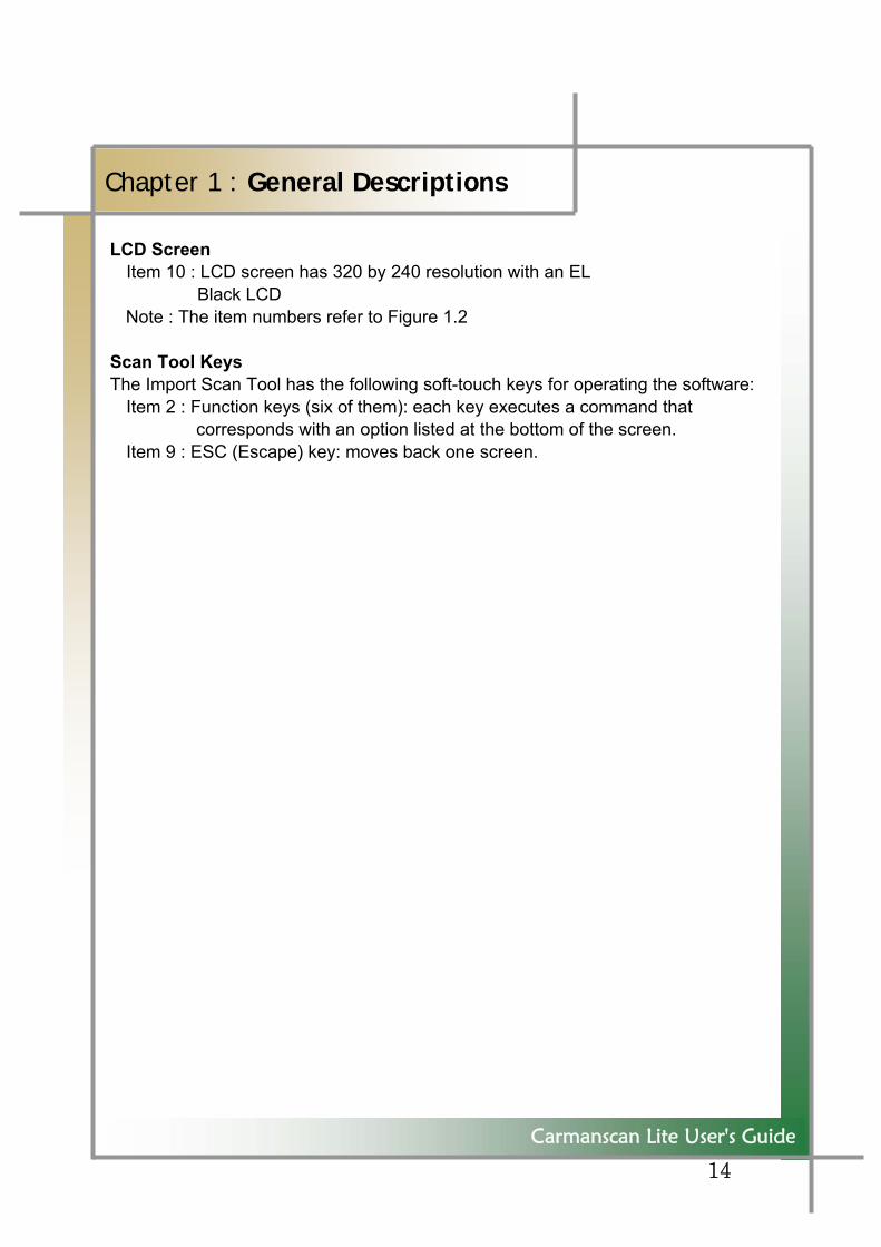
Carrying Case Figure 1.3 Carrying Case Carmanscan Lite includes a number of adaptors and cables for diagnosing vehicles. To keep the product against losing and damage, store the product in the bag when you are not using it. S/W Download CD
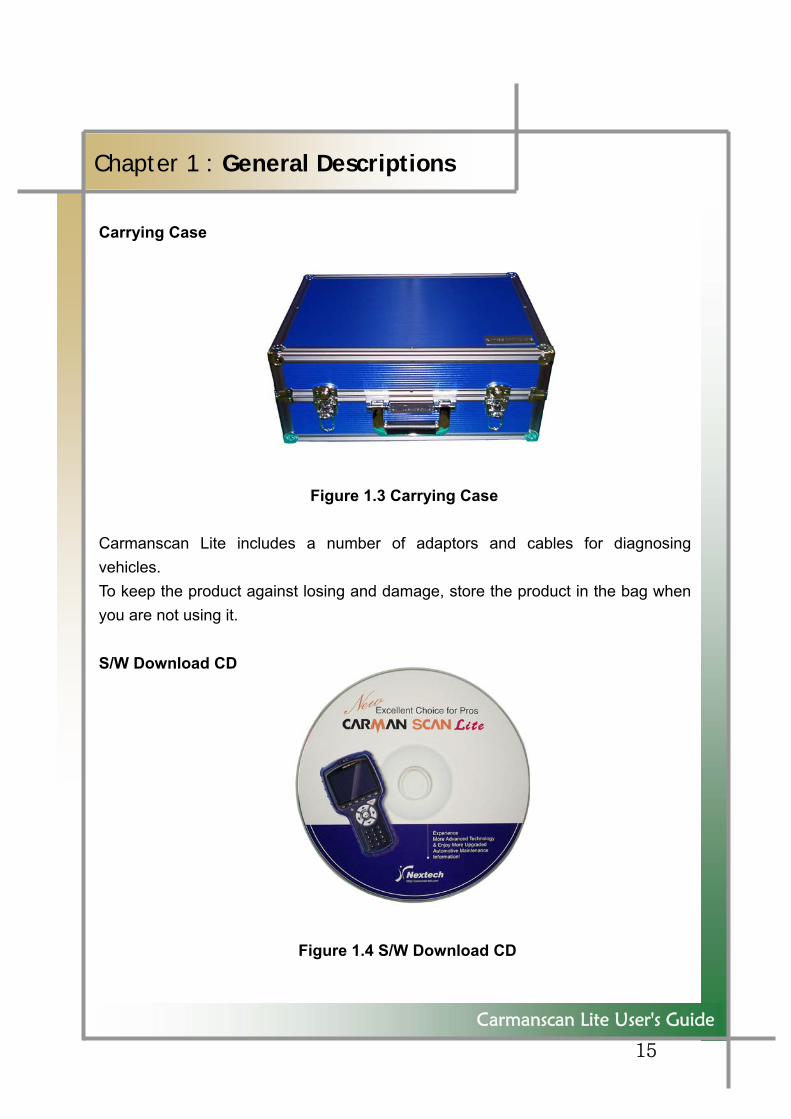
Figure 1.4 S/W Download CD
16
Carmanscan Lite User's Guide
Chapter 1 : General Descriptions
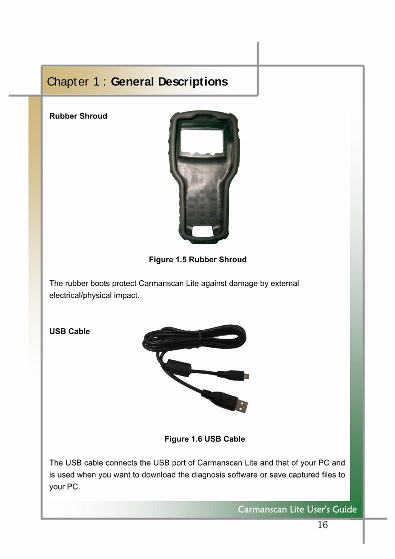
Rubber Shroud Figure 1.5 Rubber Shroud The rubber boots protect Carmanscan Lite against damage by external electrical/physical impact. USB Cable
Figure 1.6 USB Cable
The USB cable connects the USB port of Carmanscan Lite and that of your PC and is used when you want to download the diagnosis software or save captured files to your PC.
17
Carmanscan Lite User's Guide
Chapter 1 : General Descriptions
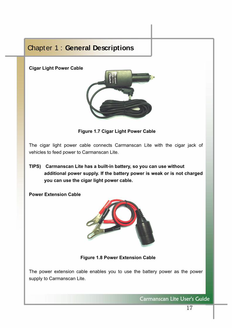
Cigar Light Power Cable Figure 1.7 Cigar Light Power Cable The cigar light power cable connects Carmanscan Lite with the cigar jack of vehicles to feed power to Carmanscan Lite. TIPS) Carmanscan Lite has a built-in battery, so you can use without
additional power supply. If the battery power is weak or is not charged you can use the cigar light power cable.
Power Extension Cable Figure 1.8 Power Extension Cable The power extension cable enables you to use the battery power as the power supply to Carmanscan Lite.
18
Carmanscan Lite User's Guide
Chapter 1 : General Descriptions
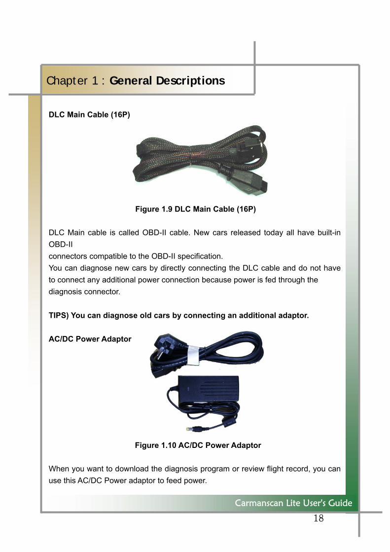
DLC Main Cable (16P) Figure 1.9 DLC Main Cable (16P) DLC Main cable is called OBD-II cable. New cars released today all have built-in OBD-II connectors compatible to the OBD-II specification. You can diagnose new cars by directly connecting the DLC cable and do not have to connect any additional power connection because power is fed through the diagnosis connector. TIPS) You can diagnose old cars by connecting an additional adaptor. AC/DC Power Adaptor
Figure 1.10 AC/DC Power Adaptor
When you want to download the diagnosis program or review flight record, you can use this AC/DC Power adaptor to feed power.
19
Carmanscan Lite User's Guide
Chapter 1 : General Descriptions
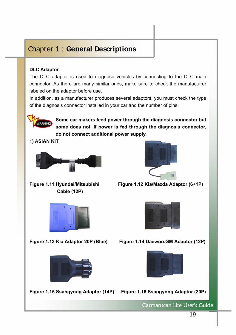
DLC Adaptor The DLC adaptor is used to diagnose vehicles by connecting to the DLC main connector. As there are many similar ones, make sure to check the manufacturer labeled on the adaptor before use. In addition, as a manufacturer produces several adaptors, you must check the type of the diagnosis connector installed in your car and the number of pins.
Some car makers feed power through the diagnosis connector but some does not. If power is fed through the diagnosis connector, do not connect additional power supply.
1) ASIAN KIT Figure 1.11 Hyundai/Mitsubishi Figure 1.12 Kia/Mazda Adaptor (6+1P)
Cable (12P) Figure 1.13 Kia Adaptor 20P (Blue) Figure 1.14 Daewoo,GM Adaptor (12P) Figure 1.15 Ssangyong Adaptor (14P) Figure 1.16 Ssangyong Adaptor (20P)
20
Carmanscan Lite User's Guide
Chapter 1 : General Descriptions
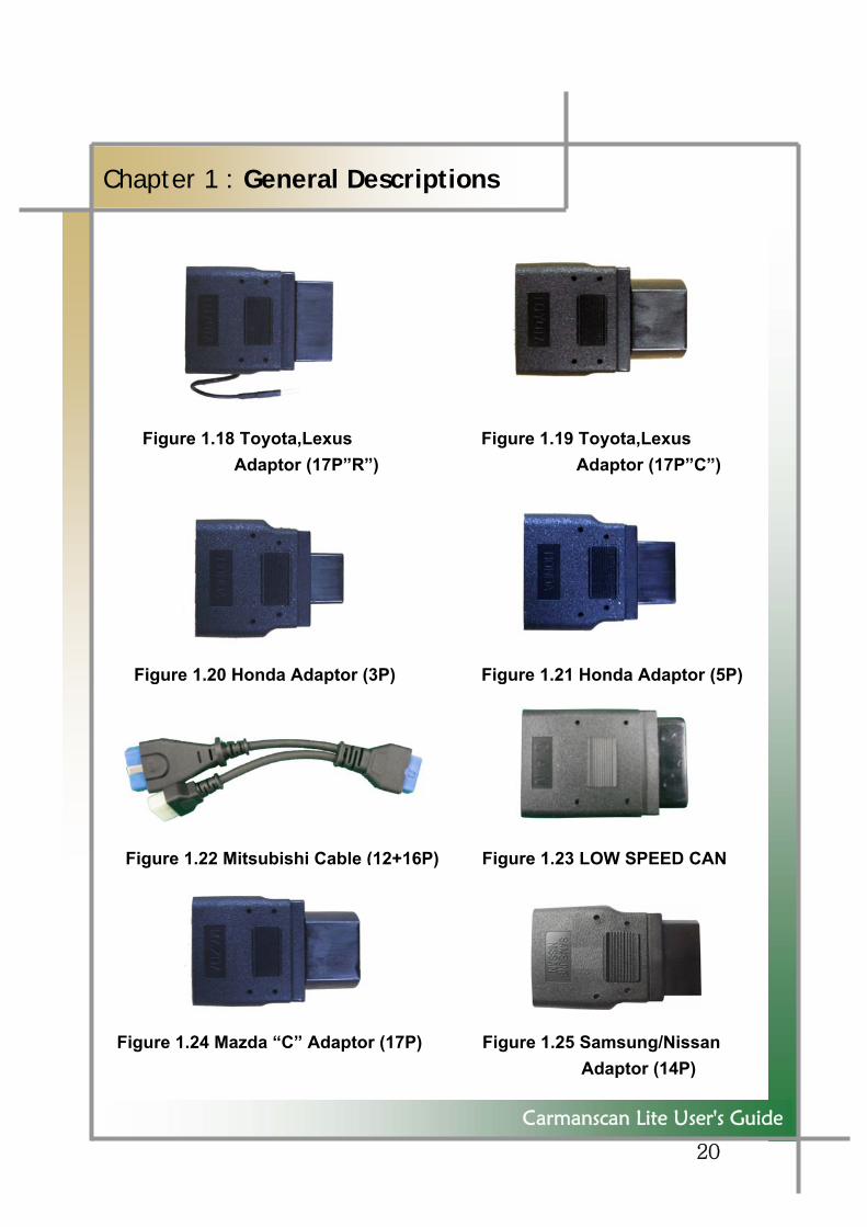
Figure 1.18 Toyota,Lexus Figure 1.19 Toyota,Lexus Adaptor (17P”R”) Adaptor (17P”C”)
Figure 1.20 Honda Adaptor (3P) Figure 1.21 Honda Adaptor (5P)
Figure 1.22 Mitsubishi Cable (12+16P) Figure 1.23 LOW SPEED CAN
Figure 1.24 Mazda “C” Adaptor (17P) Figure 1.25 Samsung/Nissan
Adaptor (14P)
21
Carmanscan Lite User's Guide
Chapter 1 : General Descriptions
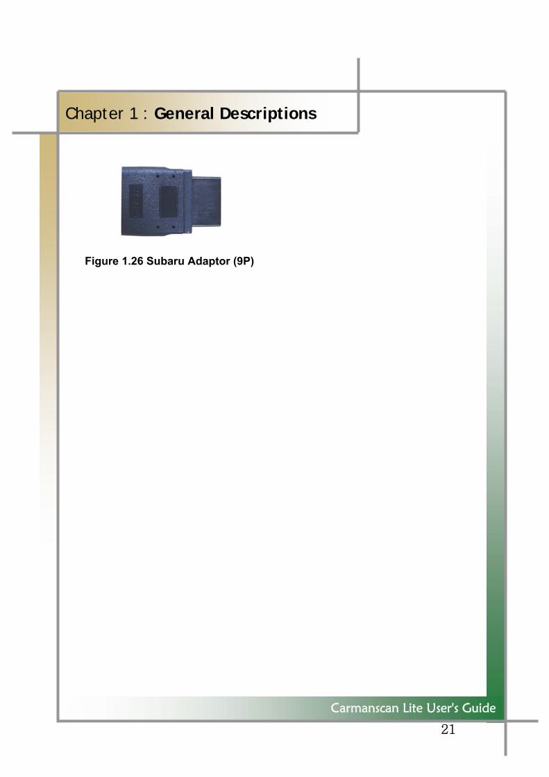
Figure 1.26 Subaru Adaptor (9P)
22
Carmanscan Lite User's Guide
Chapter 1 : General Descriptions
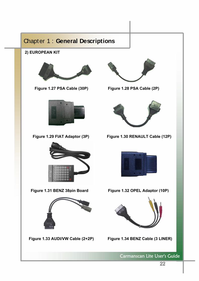
2) EUROPEAN KIT
Figure 1.27 PSA Cable (30P) Figure 1.28 PSA Cable (2P)
Figure 1.29 FIAT Adaptor (3P) Figure 1.30 RENAULT Cable (12P)
Figure 1.31 BENZ 38pin Board Figure 1.32 OPEL Adaptor (10P)
Figure 1.33 AUDI/VW Cable (2+2P) Figure 1.34 BENZ Cable (3 LINER)
23
Carmanscan Lite User's Guide
Chapter 1 : General Descriptions
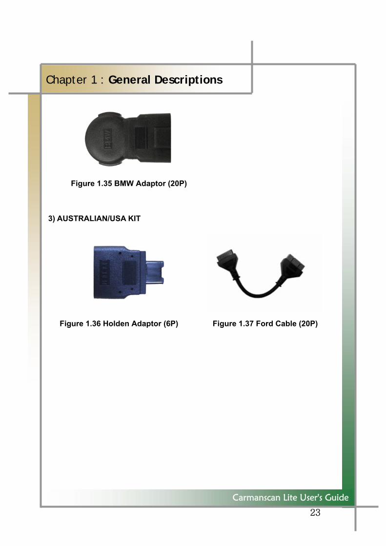
Figure 1.35 BMW Adaptor (20P) 3) AUSTRALIAN/USA KIT
Figure 1.36 Holden Adaptor (6P) Figure 1.37 Ford Cable (20P)
24
Carmanscan Lite User's Guide
Chapter 1 : General Descriptions
6. Power Supply 1. Cigar Light Power Cable Power is fed through a cigar lighter cable. But when the ignition switch is off or when you are starting the car, no power is supplied to the cigar lighter socket.
2. Car Battery Connect the (+) terminal of the battery with red cable clip and the (-) terminal with black clip to feed power using the cigar lighter cable. At this time regardless of location of the ignition switch and whether the car is started, power is always fed to the system.
As incorrectly connected electrode may give damage to the system, be careful.
3. DLC Main Cable (16p) Including vehicles that meet the OBD-II protocol, some of diagnosis connectors can be powered directly by the DLC main cable without additional power supply. 4. Battery If the built-in battery is used, you can use the system for 1 to 2 hours without power supply.
TIPS ) This may change based on use and environment. How to charge: If you do not use the system, connect the AC adapter that came with the product. Then a led light is on at the LF LED, and if the battery is fully charged a green light is on at the RF LED (See Page 11 Figure 1.2).
5. AC/DC Adaptor If the AC/DC adaptor is used for power supply, the battery will be automatically recharged depending on programs and it is also used for power supply to the main system.
25
Carmanscan Lite User's Guide
Chapter 2: Menu Configuration
1. Before Getting Started
1. Before using the system, check if the battery is fully charged. If it is not charged, then connect external power supply or recharge the battery before
you start the system. - If you use the system by connecting to a car, you can also feed power through the vehicle diagnosis connector.
If power is not fed by the vehicle diagnosis connector, you need to connect the cigar cable to feed power before you start communication with the car. Voltage mismatch between ECU and Carmanscan Lite may cause a communication error.
2. Before you use the system, you must download the diagnosis program.
The diagnosis program will be stored in the system memory. - Before you use the system, check if the diagnosis program matches the option you have purchased.
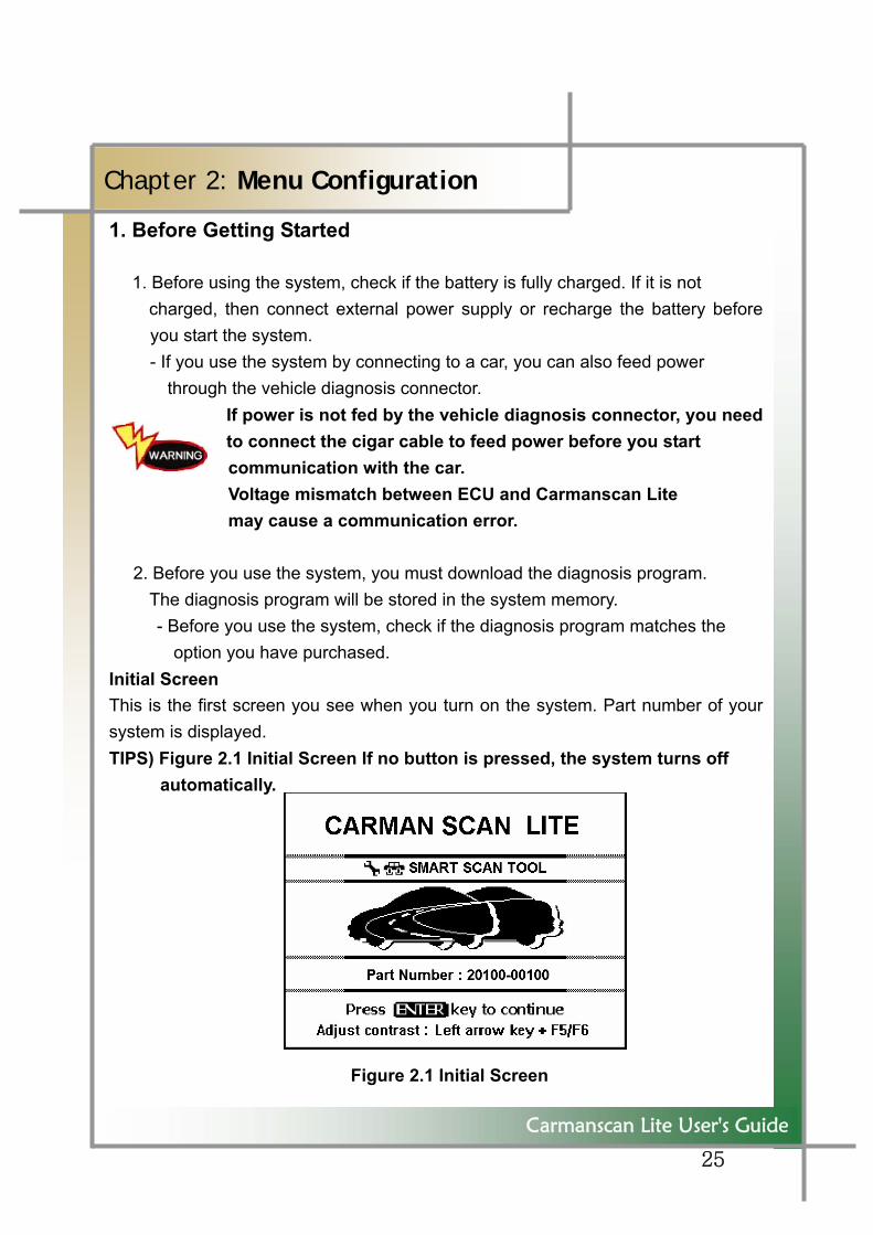
Initial Screen This is the first screen you see when you turn on the system. Part number of your system is displayed. TIPS) Figure 2.1 Initial Screen If no button is pressed, the system turns off
automatically.
Figure 2.1 Initial Screen
26
Carmanscan Lite User's Guide
Chapter 2: Menu Configuration
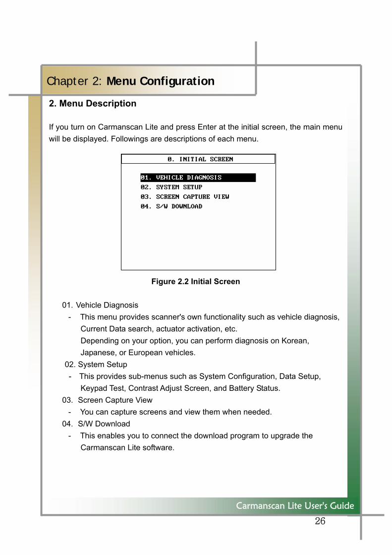
2. Menu Description If you turn on Carmanscan Lite and press Enter at the initial screen, the main menu will be displayed. Followings are descriptions of each menu.
Figure 2.2 Initial Screen
01. Vehicle Diagnosis - This menu provides scanner's own functionality such as vehicle diagnosis,
Current Data search, actuator activation, etc. Depending on your option, you can perform diagnosis on Korean, Japanese, or European vehicles.
02. System Setup - This provides sub-menus such as System Configuration, Data Setup,
Keypad Test, Contrast Adjust Screen, and Battery Status. 03. Screen Capture View
- You can capture screens and view them when needed. 04. S/W Download
- This enables you to connect the download program to upgrade the Carmanscan Lite software.
27
Carmanscan Lite User's Guide
Chapter 3: System Setup
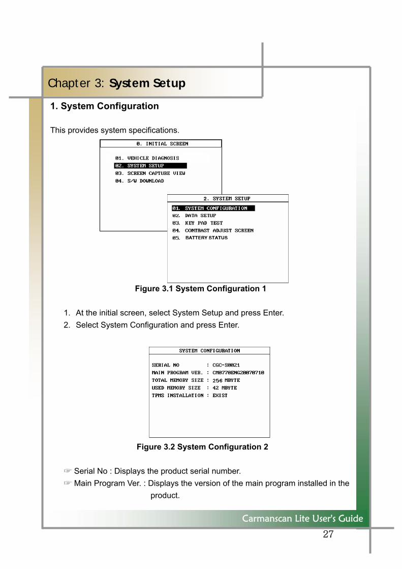
1. System Configuration This provides system specifications.
Figure 3.1 System Configuration 1
1. At the initial screen, select System Setup and press Enter. 2. Select System Configuration and press Enter.
Figure 3.2 System Configuration 2
☞ Serial No : Displays the product serial number. ☞ Main Program Ver. : Displays the version of the main program installed in the
product.
28
Carmanscan Lite User's Guide
Chapter 3: System Setup
☞ Total Memory Size : Displays the total memory size of the product. Default is 256Mbyte.
☞ Used Memory Size : Displays the memory currently used out of total memory.
☞ TPMS Installation : Displays whether TPMS diagnosis feature is installed. 3. Pressing Esc at the System Configuration screen will go back to Initial
Screen.
29
Carmanscan Lite User's Guide
Chapter 3: System Setup
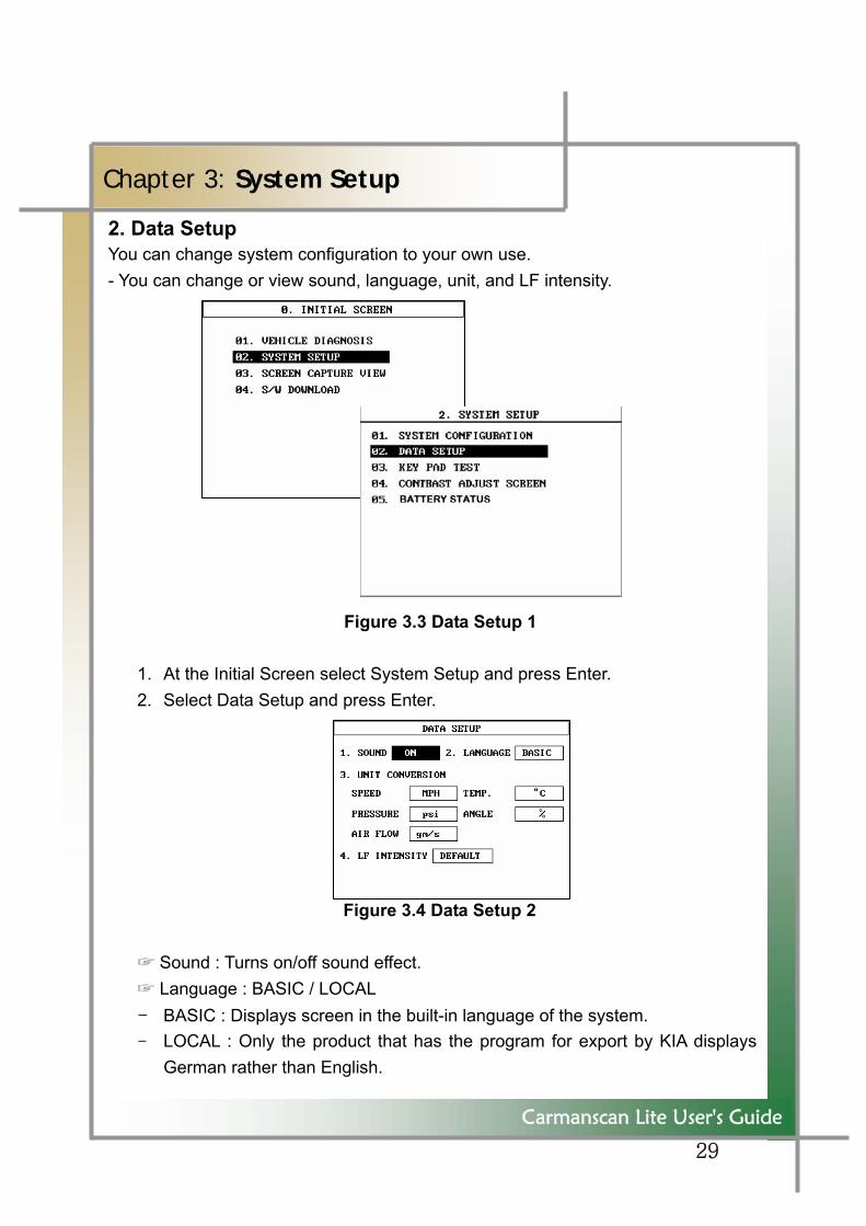
2. Data Setup You can change system configuration to your own use. - You can change or view sound, language, unit, and LF intensity. Figure 3.3 Data Setup 1
1. At the Initial Screen select System Setup and press Enter. 2. Select Data Setup and press Enter.
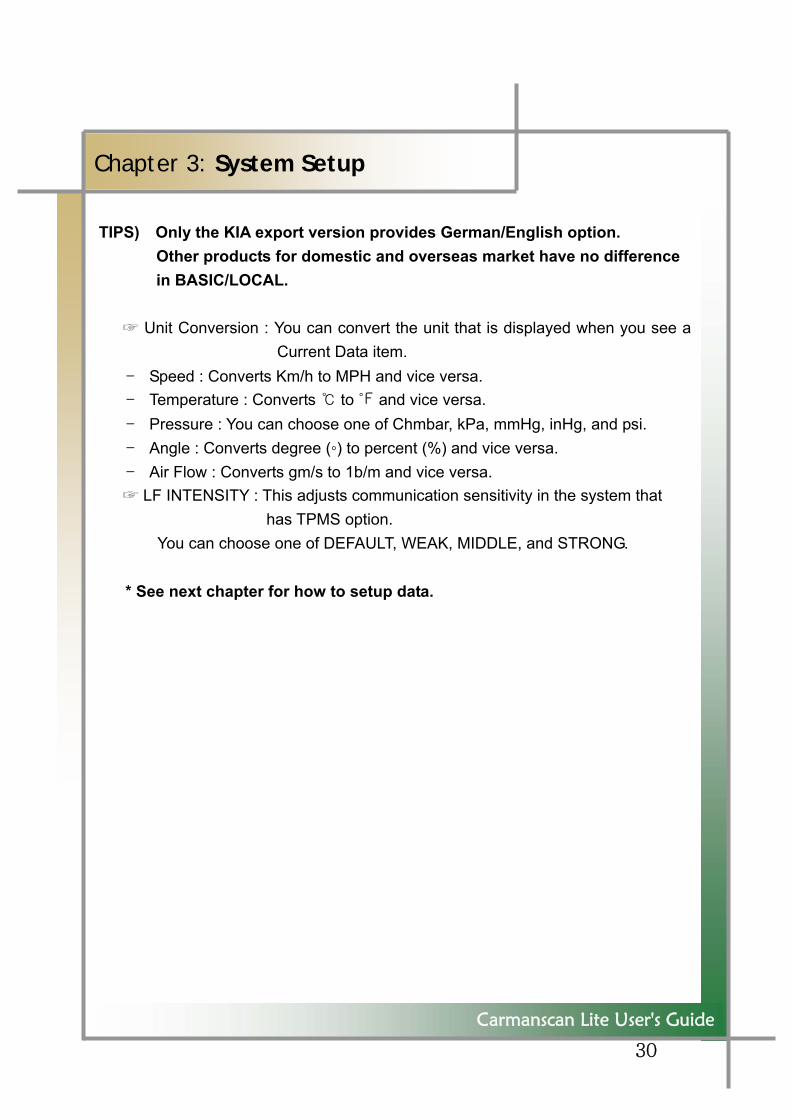
Figure 3.4 Data Setup 2
☞ Sound : Turns on/off sound effect. ☞ Language : BASIC / LOCAL - BASIC : Displays screen in the built-in language of the system. - LOCAL : Only the product that has the program for export by KIA displays
German rather than English.
30
` ` ``
Carmanscan Lite User's Guide
Chapter 3: System Setup
TIPS) Only the KIA export version provides German/English option. Other products for domestic and overseas market have no difference in BASIC/LOCAL.
☞ Unit Conversion : You can convert the unit that is displayed when you see a
Current Data item. - Speed : Converts Km/h to MPH and vice versa. - Temperature : Converts ℃ to ℉ and vice versa. - Pressure : You can choose one of Chmbar, kPa, mmHg, inHg, and psi. - Angle : Converts degree (◦) to percent (%) and vice versa. - Air Flow : Converts gm/s to 1b/m and vice versa. ☞ LF INTENSITY : This adjusts communication sensitivity in the system that
has TPMS option. You can choose one of DEFAULT, WEAK, MIDDLE, and STRONG. * See next chapter for how to setup data.
31
Carmanscan Lite User's Guide
Chapter 3: System Setup
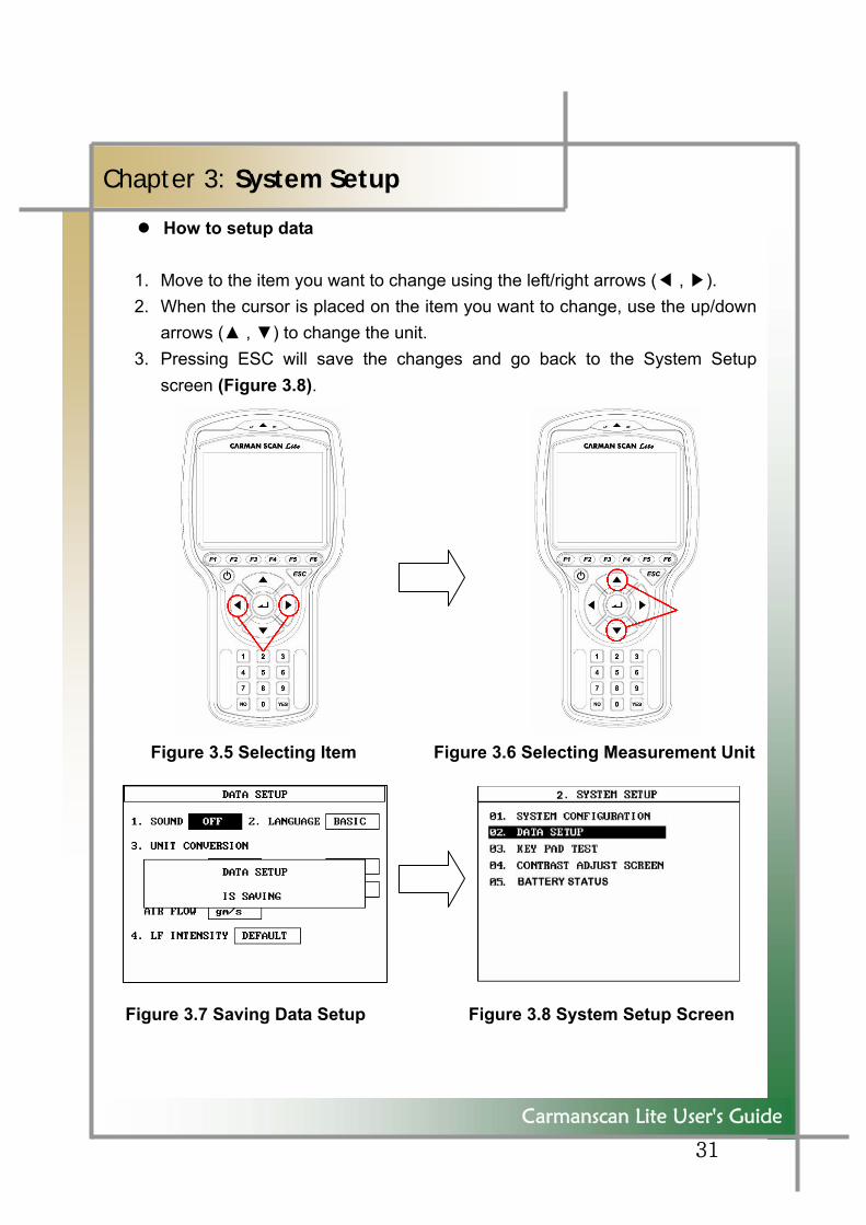
How to setup data 1. Move to the item you want to change using the left/right arrows (◀ , ▶). 2. When the cursor is placed on the item you want to change, use the up/down
arrows (▲ , ▼) to change the unit. 3. Pressing ESC will save the changes and go back to the System Setup
screen (Figure 3.8).
Figure 3.5 Selecting Item Figure 3.6 Selecting Measurement Unit
Figure 3.7 Saving Data Setup Figure 3.8 System Setup Screen
32
Carmanscan Lite User's Guide
Chapter 3: System Setup
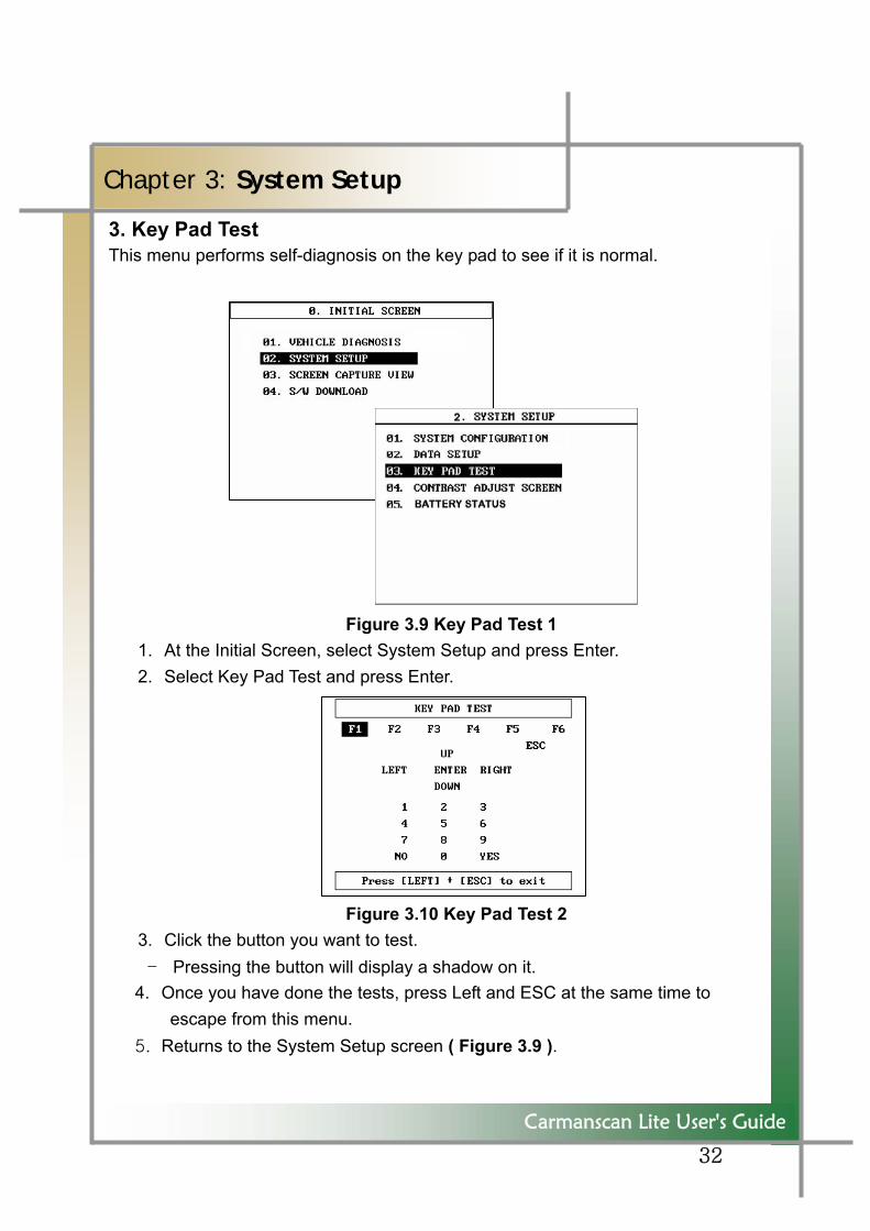
3. Key Pad Test This menu performs self-diagnosis on the key pad to see if it is normal.
Figure 3.9 Key Pad Test 1 1. At the Initial Screen, select System Setup and press Enter. 2. Select Key Pad Test and press Enter.
Figure 3.10 Key Pad Test 2 3. Click the button you want to test. - Pressing the button will display a shadow on it.
4. Once you have done the tests, press Left and ESC at the same time to escape from this menu.
5. Returns to the System Setup screen ( Figure 3.9 ).
33
Figure 1.49 Battery Status 2
Carmanscan Lite User's Guide
Chapter 3: System Setup
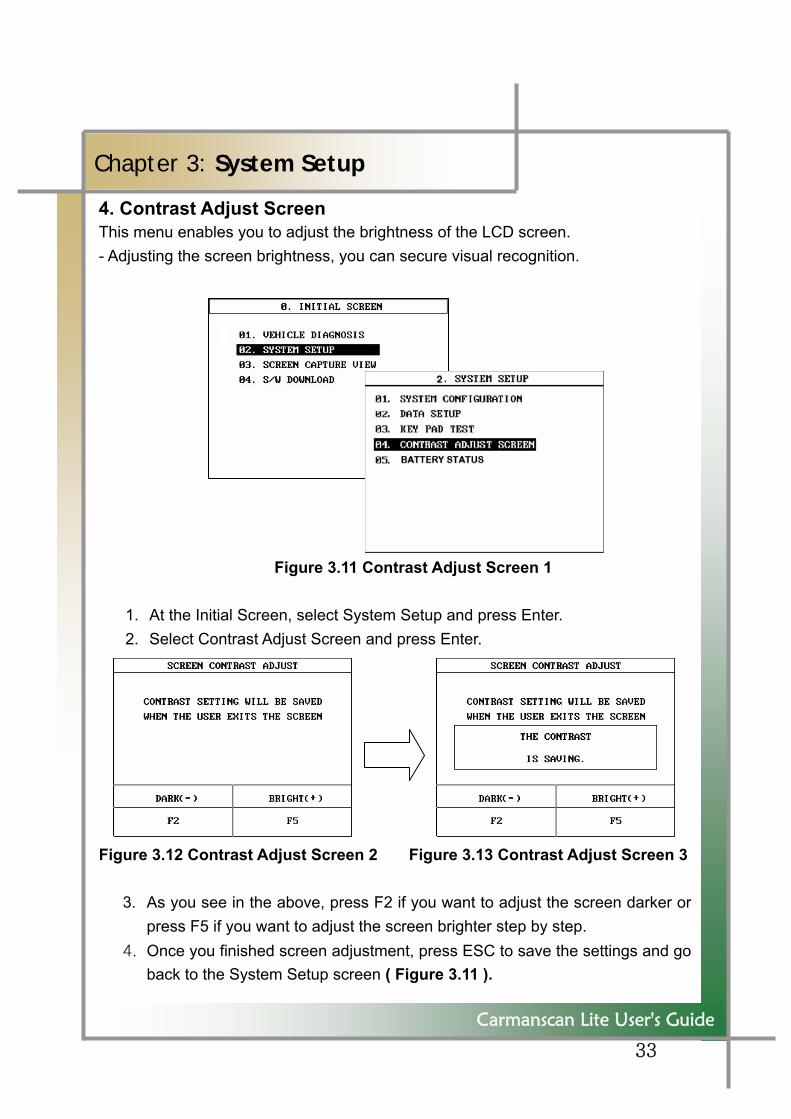
4. Contrast Adjust Screen This menu enables you to adjust the brightness of the LCD screen. - Adjusting the screen brightness, you can secure visual recognition. Figure 3.11 Contrast Adjust Screen 1
1. At the Initial Screen, select System Setup and press Enter. 2. Select Contrast Adjust Screen and press Enter.
Figure 3.12 Contrast Adjust Screen 2 Figure 3.13 Contrast Adjust Screen 3
3. As you see in the above, press F2 if you want to adjust the screen darker or
press F5 if you want to adjust the screen brighter step by step. 4. Once you finished screen adjustment, press ESC to save the settings and go
back to the System Setup screen ( Figure 3.11 ).
34
Carmanscan Lite User's Guide
Chapter 3: System Setup
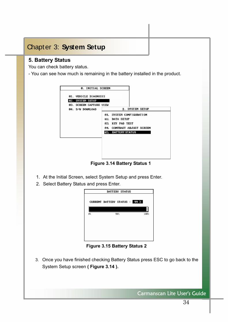
5. Battery Status You can check battery status. - You can see how much is remaining in the battery installed in the product. Figure 3.14 Battery Status 1
1. At the Initial Screen, select System Setup and press Enter. 2. Select Battery Status and press Enter.
Figure 3.15 Battery Status 2
3. Once you have finished checking Battery Status press ESC to go back to the System Setup screen ( Figure 3.14 ).
35
Carmanscan Lite User's Guide
Chapter 4: Screen Capture View
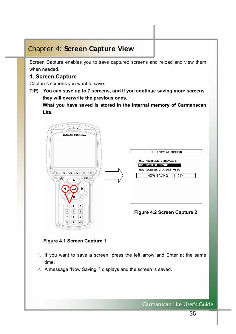
Screen Capture enables you to save captured screens and reload and view them when needed. 1. Screen Capture Captures screens you want to save. TIP) You can save up to 7 screens, and if you continue saving more screens
they will overwrite the previous ones. What you have saved is stored in the internal memory of Carmanscan Lite.
Figure 4.2 Screen Capture 2
Figure 4.1 Screen Capture 1
1. If you want to save a screen, press the left arrow and Enter at the same time.
2. A message “Now Saving! ” displays and the screen is saved.
36
Carmanscan Lite User's Guide
Chapter 4: Screen Capture View
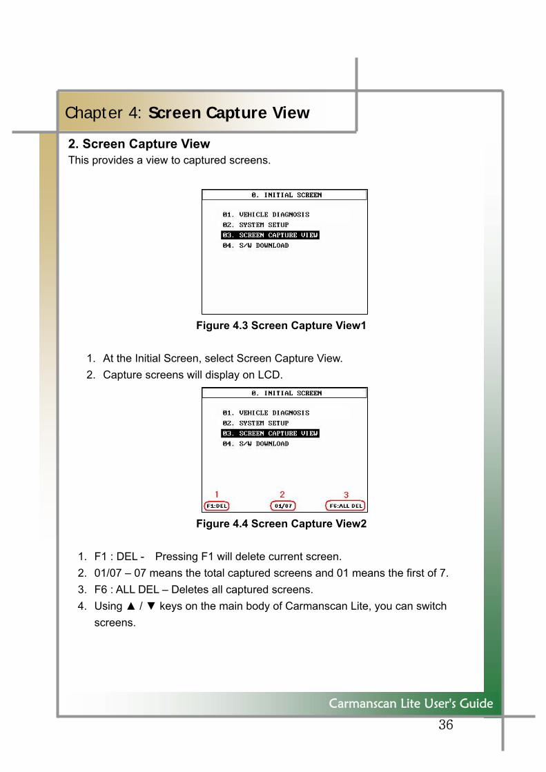
2. Screen Capture View This provides a view to captured screens.
Figure 4.3 Screen Capture View1
1. At the Initial Screen, select Screen Capture View. 2. Capture screens will display on LCD.
Figure 4.4 Screen Capture View2
1. F1 : DEL - Pressing F1 will delete current screen. 2. 01/07 – 07 means the total captured screens and 01 means the first of 7. 3. F6 : ALL DEL – Deletes all captured screens. 4. Using ▲ / ▼ keys on the main body of Carmanscan Lite, you can switch
screens.
37
Carmanscan Lite User's Guide
Chapter 5: S/W Download
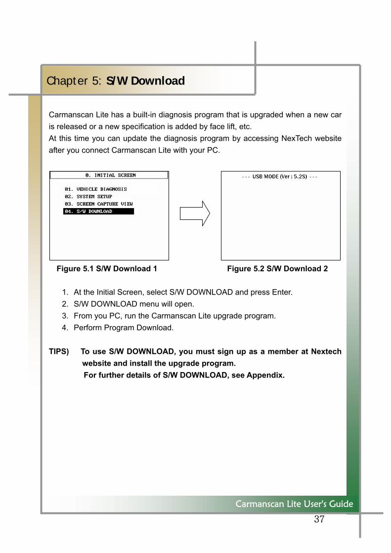
Carmanscan Lite has a built-in diagnosis program that is upgraded when a new car is released or a new specification is added by face lift, etc. At this time you can update the diagnosis program by accessing NexTech website after you connect Carmanscan Lite with your PC.
Figure 5.1 S/W Download 1 Figure 5.2 S/W Download 2
1. At the Initial Screen, select S/W DOWNLOAD and press Enter. 2. S/W DOWNLOAD menu will open. 3. From you PC, run the Carmanscan Lite upgrade program. 4. Perform Program Download.
TIPS) To use S/W DOWNLOAD, you must sign up as a member at Nextech website and install the upgrade program.
For further details of S/W DOWNLOAD, see Appendix.
38
Carmanscan Lite User's Guide
Chapter 6: Selecting Diagnosis Menu
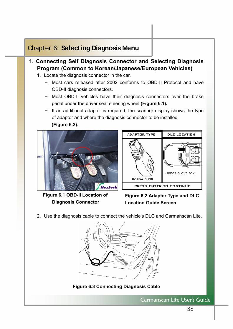
1. Connecting Self Diagnosis Connector and Selecting Diagnosis Program (Common to Korean/Japanese/European Vehicles) 1. Locate the diagnosis connector in the car.
- Most cars released after 2002 conforms to OBD-II Protocol and have OBD-II diagnosis connectors.
- Most OBD-II vehicles have their diagnosis connectors over the brake pedal under the driver seat steering wheel (Figure 6.1).
- If an additional adaptor is required, the scanner display shows the type of adaptor and where the diagnosis connector to be installed (Figure 6.2).
Figure 6.1 OBD-II Location of Diagnosis Connector
2. Use the diagnosis cable to connect the vehicle's DLC and Carmanscan Lite.
Figure 6.3 진단 cable 연결
Figure 6.3 Connecting Diagnosis Cable
Figure 6.2 Adapter Type and DLC Location Guide Screen
39
Carmanscan Lite User's Guide
Chapter 6: Selecting Diagnosis Menu
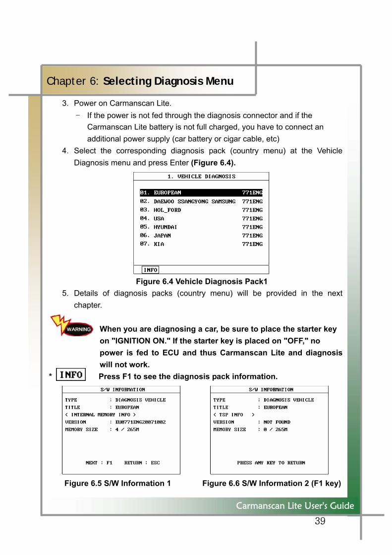
3. Power on Carmanscan Lite. - If the power is not fed through the diagnosis connector and if the
Carmanscan Lite battery is not full charged, you have to connect an additional power supply (car battery or cigar cable, etc)
4. Select the corresponding diagnosis pack (country menu) at the Vehicle Diagnosis menu and press Enter (Figure 6.4).
Figure 6.4 Vehicle Diagnosis Pack1
5. Details of diagnosis packs (country menu) will be provided in the next chapter.
When you are diagnosing a car, be sure to place the starter key on "IGNITION ON." If the starter key is placed on "OFF," no power is fed to ECU and thus Carmanscan Lite and diagnosis will not work.
* Press F1 to see the diagnosis pack information.
Figure 6.5 S/W Information 1 Figure 6.6 S/W Information 2 (F1 key)
40
Figure 6.8 Selecting Vehicle Type Diagnosis
Carmanscan Lite User's Guide
Chapter 6: Selecting Diagnosis Menu
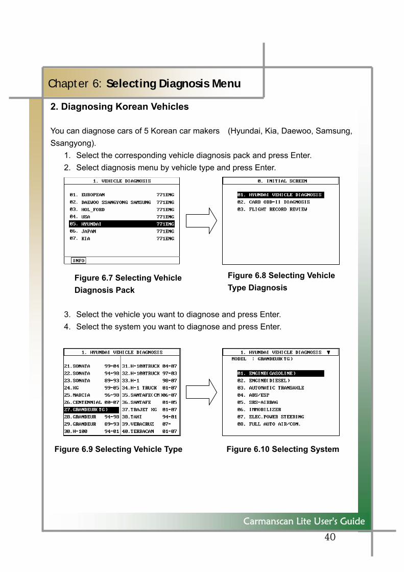
2. Diagnosing Korean Vehicles
You can diagnose cars of 5 Korean car makers (Hyundai, Kia, Daewoo, Samsung,Ssangyong).
1. Select the corresponding vehicle diagnosis pack and press Enter. 2. Select diagnosis menu by vehicle type and press Enter.
Figure 6.7 Selecting Vehicle Diagnosis Pack
3. Select the vehicle you want to diagnose and press Enter. 4. Select the system you want to diagnose and press Enter.
Figure 6.9 Selecting Vehicle Type Figure 6.10 Selecting System
41
Carmanscan Lite User's Guide
Chapter 6: Selecting Diagnosis Menu
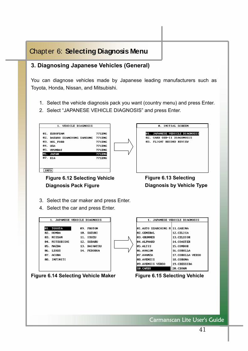
3. Diagnosing Japanese Vehicles (General)
You can diagnose vehicles made by Japanese leading manufacturers such as Toyota, Honda, Nissan, and Mitsubishi.
1. Select the vehicle diagnosis pack you want (country menu) and press Enter. 2. Select “JAPANESE VEHICLE DIAGNOSIS” and press Enter.
Figure 6.12 Selecting Vehicle Diagnosis Pack Figure
3. Select the car maker and press Enter. 4. Select the car and press Enter.
Figure 6.14 Selecting Vehicle Maker Figure 6.15 Selecting Vehicle
Figure 6.13 Selecting Diagnosis by Vehicle Type
42
Carmanscan Lite User's Guide
Chapter 6: Selecting Diagnosis Menu
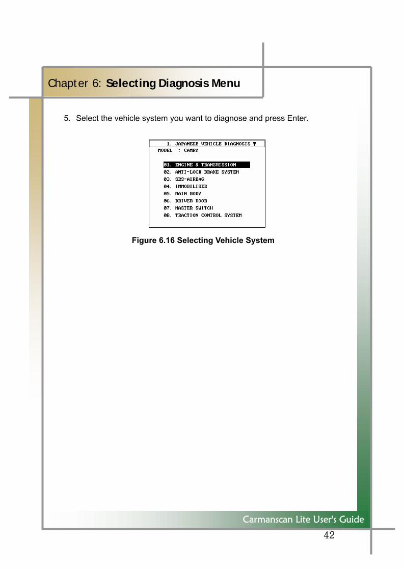
5. Select the vehicle system you want to diagnose and press Enter.
Figure 6.16 Selecting Vehicle System
43
Carmanscan Lite User's Guide
Chapter 6: Selecting Diagnosis Menu
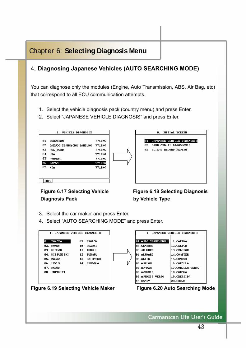
4. Diagnosing Japanese Vehicles (AUTO SEARCHING MODE)
You can diagnose only the modules (Engine, Auto Transmission, ABS, Air Bag, etc) that correspond to all ECU communication attempts.
1. Select the vehicle diagnosis pack (country menu) and press Enter. 2. Select “JAPANESE VEHICLE DIAGNOSIS” and press Enter.
Figure 6.17 Selecting Vehicle Figure 6.18 Selecting Diagnosis Diagnosis Pack by Vehicle Type
3. Select the car maker and press Enter. 4. Select “AUTO SEARCHING MODE” and press Enter.
Figure 6.19 Selecting Vehicle Maker Figure 6.20 Auto Searching Mode
44
Carmanscan Lite User's Guide
Chapter 6: Selecting Diagnosis Menu
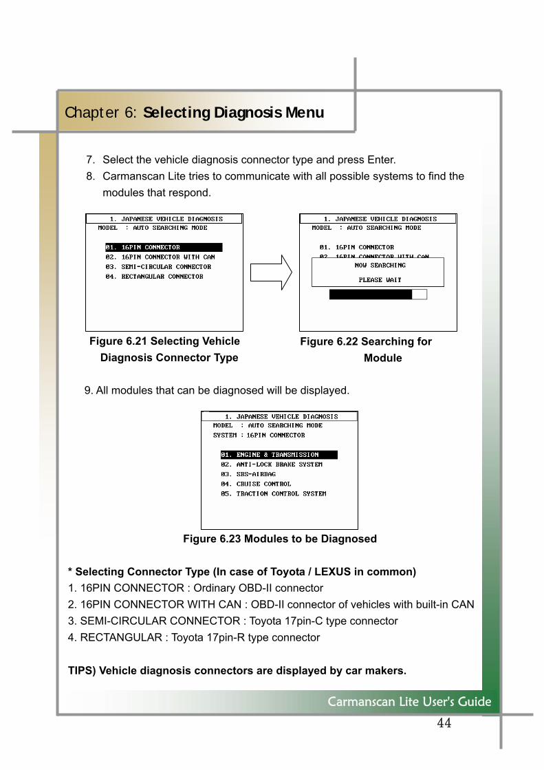
7. Select the vehicle diagnosis connector type and press Enter. 8. Carmanscan Lite tries to communicate with all possible systems to find the
modules that respond.
Figure 6.21 Selecting Vehicle Diagnosis Connector Type
9. All modules that can be diagnosed will be displayed.
Figure 6.23 Modules to be Diagnosed
* Selecting Connector Type (In case of Toyota / LEXUS in common) 1. 16PIN CONNECTOR : Ordinary OBD-II connector 2. 16PIN CONNECTOR WITH CAN : OBD-II connector of vehicles with built-in CAN3. SEMI-CIRCULAR CONNECTOR : Toyota 17pin-C type connector 4. RECTANGULAR : Toyota 17pin-R type connector TIPS) Vehicle diagnosis connectors are displayed by car makers.
Figure 6.22 Searching for Module
45
Carmanscan Lite User's Guide
Chapter 6: Selecting Diagnosis Menu
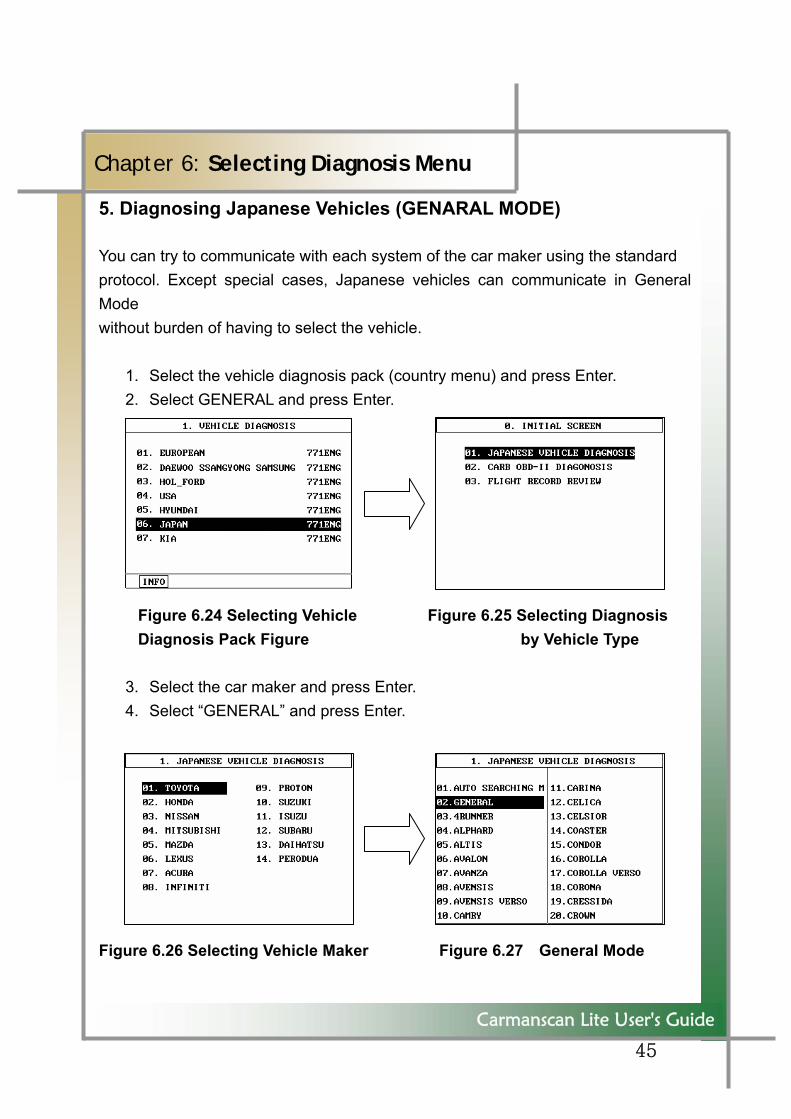
5. Diagnosing Japanese Vehicles (GENARAL MODE)
You can try to communicate with each system of the car maker using the standard protocol. Except special cases, Japanese vehicles can communicate in General Mode without burden of having to select the vehicle.
1. Select the vehicle diagnosis pack (country menu) and press Enter. 2. Select GENERAL and press Enter.
Figure 6.24 Selecting Vehicle Figure 6.25 Selecting Diagnosis Diagnosis Pack Figure by Vehicle Type
3. Select the car maker and press Enter. 4. Select “GENERAL” and press Enter.
Figure 6.26 Selecting Vehicle Maker Figure 6.27 General Mode
46
Carmanscan Lite User's Guide
Chapter 6: Selecting Diagnosis Menu
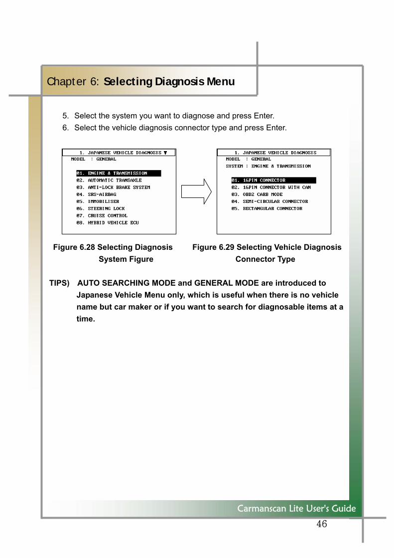
5. Select the system you want to diagnose and press Enter. 6. Select the vehicle diagnosis connector type and press Enter.
Figure 6.28 Selecting Diagnosis Figure 6.29 Selecting Vehicle Diagnosis
System Figure Connector Type
TIPS) AUTO SEARCHING MODE and GENERAL MODE are introduced to Japanese Vehicle Menu only, which is useful when there is no vehicle name but car maker or if you want to search for diagnosable items at a time.
47
Carmanscan Lite User's Guide
Chapter 6: Selecting Diagnosis Menu
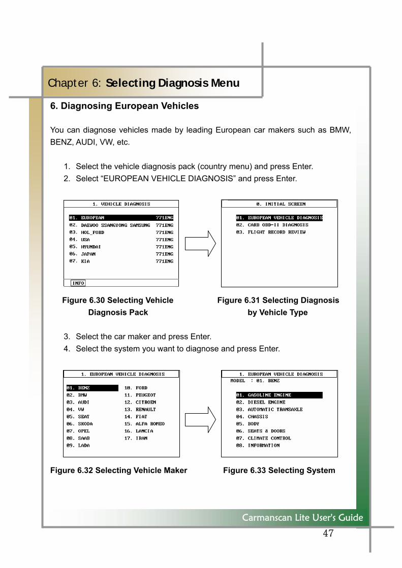
6. Diagnosing European Vehicles
You can diagnose vehicles made by leading European car makers such as BMW, BENZ, AUDI, VW, etc.
1. Select the vehicle diagnosis pack (country menu) and press Enter. 2. Select “EUROPEAN VEHICLE DIAGNOSIS” and press Enter.
Figure 6.30 Selecting Vehicle Figure 6.31 Selecting Diagnosis Diagnosis Pack by Vehicle Type
3. Select the car maker and press Enter. 4. Select the system you want to diagnose and press Enter.
Figure 6.32 Selecting Vehicle Maker Figure 6.33 Selecting System
48
Carmanscan Lite User's Guide
Chapter 6: Selecting Diagnosis Menu
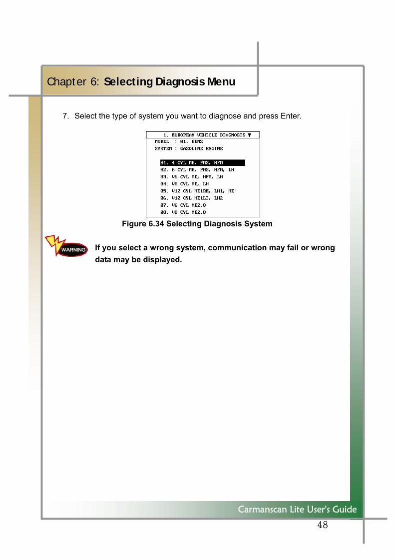
7. Select the type of system you want to diagnose and press Enter.
Figure 6.34 Selecting Diagnosis System
If you select a wrong system, communication may fail or wrong data may be displayed.
49
Carmanscan Lite User's Guide
Chapter 7: Vehicle Diagnosis
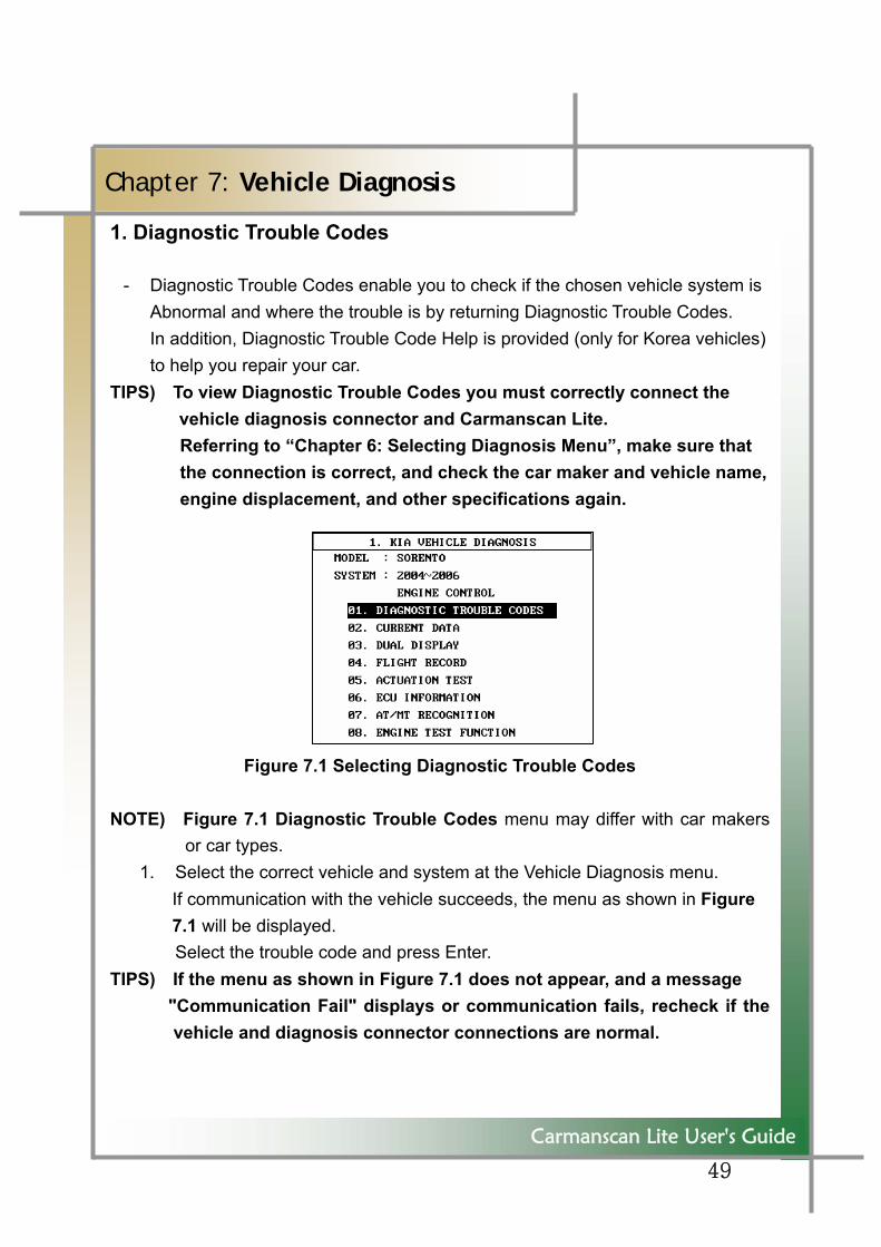
1. Diagnostic Trouble Codes
- Diagnostic Trouble Codes enable you to check if the chosen vehicle system is Abnormal and where the trouble is by returning Diagnostic Trouble Codes. In addition, Diagnostic Trouble Code Help is provided (only for Korea vehicles) to help you repair your car.
TIPS) To view Diagnostic Trouble Codes you must correctly connect the vehicle diagnosis connector and Carmanscan Lite.
Referring to “Chapter 6: Selecting Diagnosis Menu”, make sure that the connection is correct, and check the car maker and vehicle name, engine displacement, and other specifications again.
Figure 7.1 Selecting Diagnostic Trouble Codes NOTE) Figure 7.1 Diagnostic Trouble Codes menu may differ with car makers
or car types. 1. Select the correct vehicle and system at the Vehicle Diagnosis menu.
If communication with the vehicle succeeds, the menu as shown in Figure 7.1 will be displayed. Select the trouble code and press Enter.
TIPS) If the menu as shown in Figure 7.1 does not appear, and a message "Communication Fail" displays or communication fails, recheck if the
vehicle and diagnosis connector connections are normal.
50
Carmanscan Lite User's Guide
Chapter 7: Vehicle Diagnosis
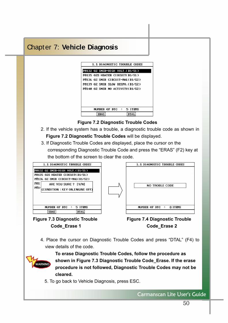
Figure 7.2 Diagnostic Trouble Codes 2. If the vehicle system has a trouble, a diagnostic trouble code as shown in
Figure 7.2 Diagnostic Trouble Codes will be displayed. 3. If Diagnostic Trouble Codes are displayed, place the cursor on the
corresponding Diagnostic Trouble Code and press the “ERAS” (F2) key at the bottom of the screen to clear the code.
Figure 7.3 Diagnostic Trouble Figure 7.4 Diagnostic Trouble Code_Erase 1 Code_Erase 2
4. Place the cursor on Diagnostic Trouble Codes and press “DTAL” (F4) to
view details of the code. To erase Diagnostic Trouble Codes, follow the procedure as shown in Figure 7.3 Diagnostic Trouble Code_Erase. If the erase procedure is not followed, Diagnostic Trouble Codes may not be cleared.
5. To go back to Vehicle Diagnosis, press ESC.
51
Carmanscan Lite User's Guide
Chapter 7: Vehicle Diagnosis
TIPS) Diagnostic Trouble Codes have two types: the past diagnostic trouble codes and the present diagnostic trouble cod. If the diagnostic
trouble code is pastone it will immediately removed and will not reappear, but if the code ispresent one it will be cleared temporarily but reappear soon. In thiscase, you need to clear the trouble code again after you check the part that caused the diagnostic trouble code and repair the part.
52
Carmanscan Lite User's Guide
Chapter 7: Vehicle Diagnosis
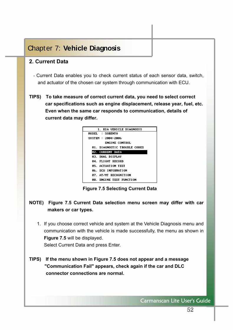
2. Current Data
- Current Data enables you to check current status of each sensor data, switch, and actuator of the chosen car system through communication with ECU.
TIPS) To take measure of correct current data, you need to select correct
car specifications such as engine displacement, release year, fuel, etc. Even when the same car responds to communication, details of
current data may differ.
Figure 7.5 Selecting Current Data
NOTE) Figure 7.5 Current Data selection menu screen may differ with car makers or car types.
1. If you choose correct vehicle and system at the Vehicle Diagnosis menu and
communication with the vehicle is made successfully, the menu as shown in Figure 7.5 will be displayed. Select Current Data and press Enter.
TIPS) If the menu shown in Figure 7.5 does not appear and a message "Communication Fail" appears, check again if the car and DLC
connector connections are normal.
53
Carmanscan Lite User's Guide
Chapter 7: Vehicle Diagnosis
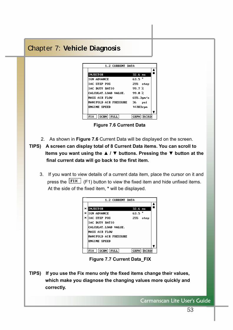
Figure 7.6 Current Data
2. As shown in Figure 7.6 Current Data will be displayed on the screen. TIPS) A screen can display total of 8 Current Data items. You can scroll to
Items you want using the ▲ / ▼ buttons. Pressing the ▼ button at the final current data will go back to the first item.
3. If you want to view details of a current data item, place the cursor on it and
press the (F1) button to view the fixed item and hide unfixed items. At the side of the fixed item, * will be displayed.
Figure 7.7 Current Data_FIX
TIPS) If you use the Fix menu only the fixed items change their values, which make you diagnose the changing values more quickly and correctly.
54
Carmanscan Lite User's Guide
Chapter 7: Vehicle Diagnosis
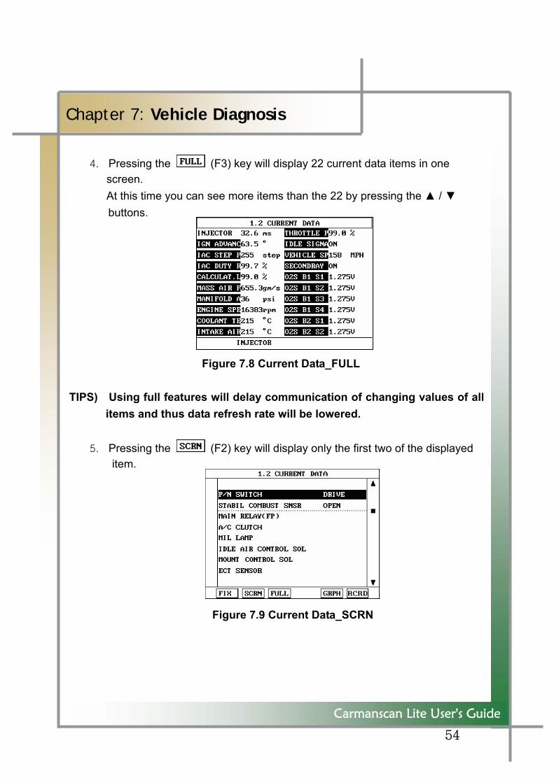
4. Pressing the (F3) key will display 22 current data items in one screen.
At this time you can see more items than the 22 by pressing the ▲ / ▼ buttons.
Figure 7.8 Current Data_FULL
TIPS) Using full features will delay communication of changing values of all
items and thus data refresh rate will be lowered.
5. Pressing the (F2) key will display only the first two of the displayed item.
Figure 7.9 Current Data_SCRN
55
Carmanscan Lite User's Guide
Chapter 7: Vehicle Diagnosis
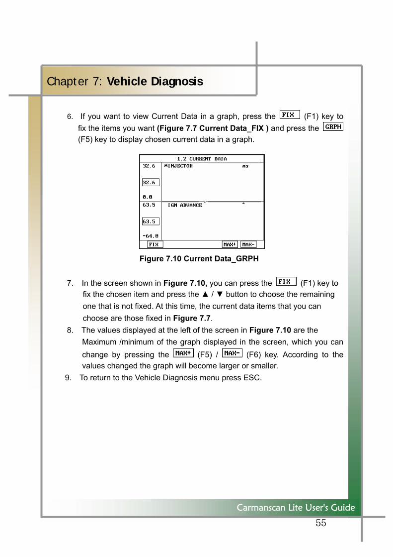
6. If you want to view Current Data in a graph, press the (F1) key to fix the items you want (Figure 7.7 Current Data_FIX ) and press the (F5) key to display chosen current data in a graph.
Figure 7.10 Current Data_GRPH
7. In the screen shown in Figure 7.10, you can press the (F1) key to fix the chosen item and press the ▲ / ▼ button to choose the remaining one that is not fixed. At this time, the current data items that you can choose are those fixed in Figure 7.7.
8. The values displayed at the left of the screen in Figure 7.10 are the Maximum /minimum of the graph displayed in the screen, which you can
change by pressing the (F5) / (F6) key. According to the values changed the graph will become larger or smaller.
9. To return to the Vehicle Diagnosis menu press ESC.
56
Carmanscan Lite User's Guide
Chapter 7: Vehicle Diagnosis
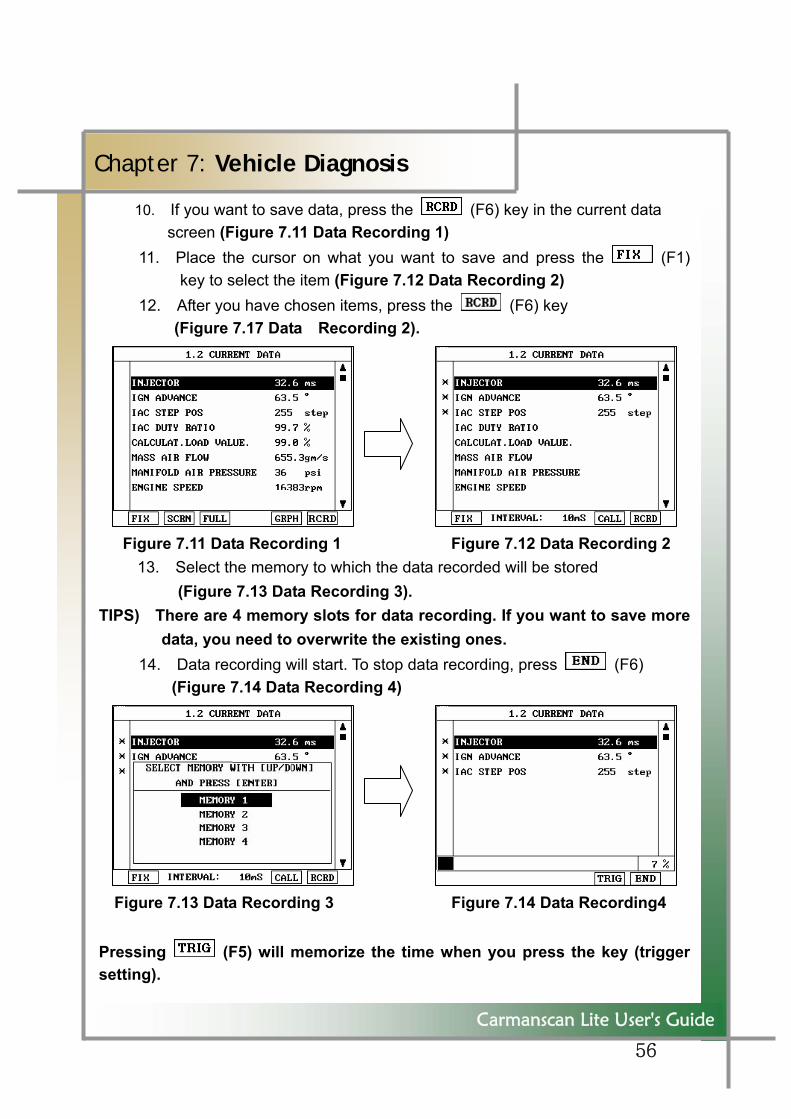
10. If you want to save data, press the (F6) key in the current data screen (Figure 7.11 Data Recording 1)
11. Place the cursor on what you want to save and press the (F1) key to select the item (Figure 7.12 Data Recording 2)
12. After you have chosen items, press the (F6) key (Figure 7.17 Data Recording 2).
Figure 7.11 Data Recording 1 Figure 7.12 Data Recording 2
13. Select the memory to which the data recorded will be stored (Figure 7.13 Data Recording 3).
TIPS) There are 4 memory slots for data recording. If you want to save more data, you need to overwrite the existing ones.
14. Data recording will start. To stop data recording, press (F6) (Figure 7.14 Data Recording 4)
Figure 7.13 Data Recording 3 Figure 7.14 Data Recording4 Pressing (F5) will memorize the time when you press the key (trigger setting).
57
Carmanscan Lite User's Guide
Chapter 7: Vehicle Diagnosis
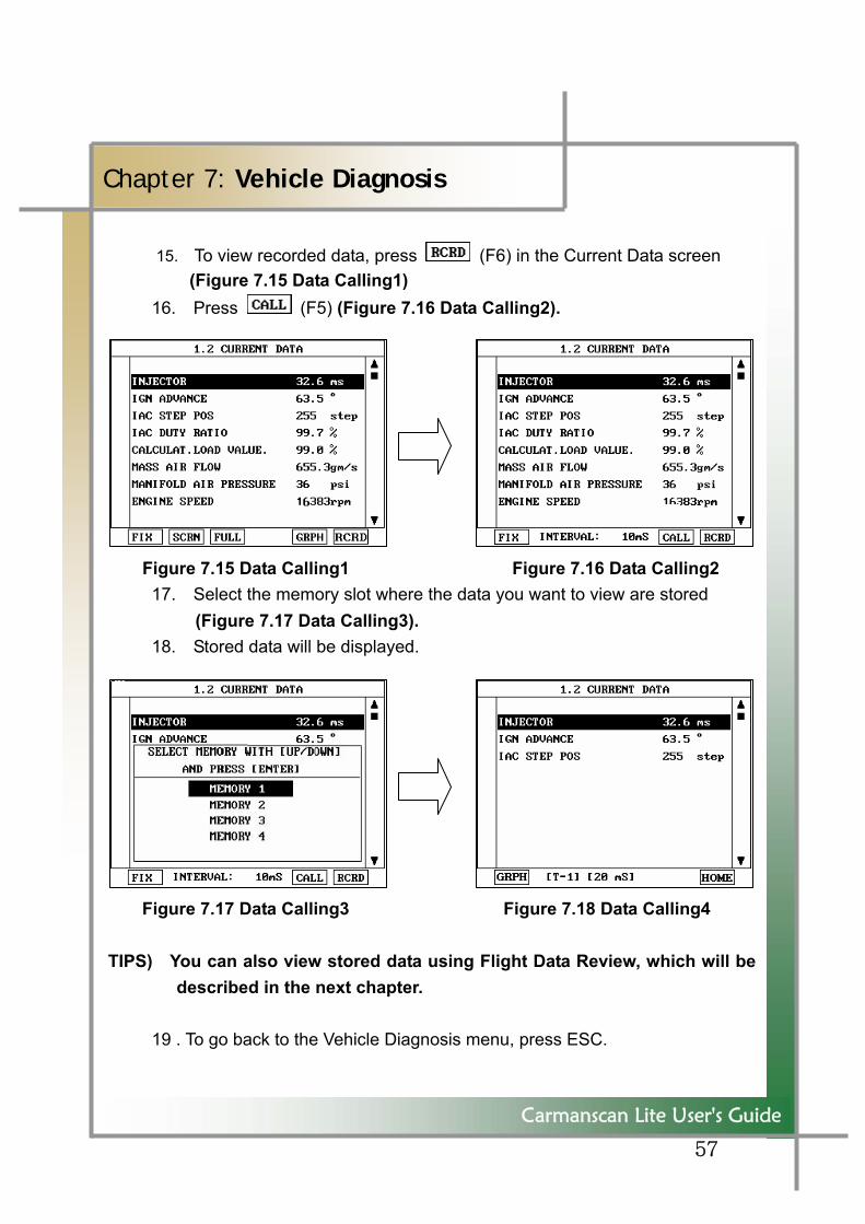
15. To view recorded data, press (F6) in the Current Data screen (Figure 7.15 Data Calling1)
16. Press (F5) (Figure 7.16 Data Calling2).
Figure 7.15 Data Calling1 Figure 7.16 Data Calling2 17. Select the memory slot where the data you want to view are stored (Figure 7.17 Data Calling3). 18. Stored data will be displayed.
Figure 7.17 Data Calling3 Figure 7.18 Data Calling4 TIPS) You can also view stored data using Flight Data Review, which will be
described in the next chapter. 19 . To go back to the Vehicle Diagnosis menu, press ESC.
58
Carmanscan Lite User's Guide
Chapter 7: Vehicle Diagnosis
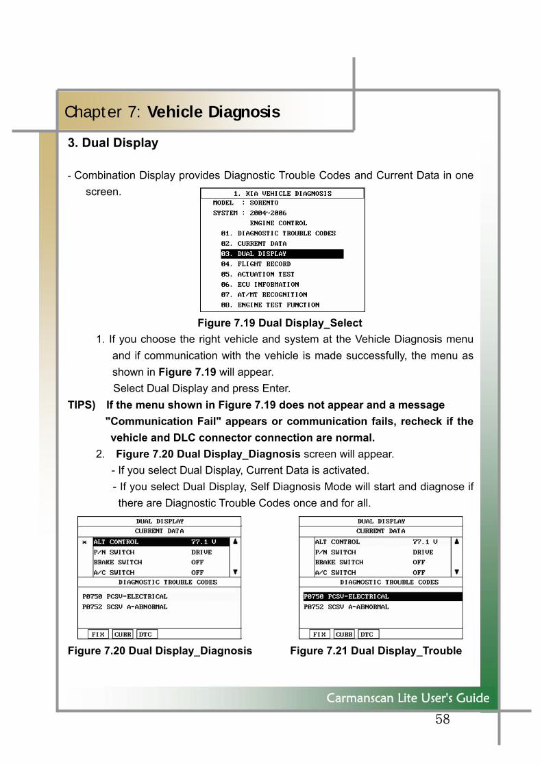
3. Dual Display
- Combination Display provides Diagnostic Trouble Codes and Current Data in one screen.
Figure 7.19 Dual Display_Select 1. If you choose the right vehicle and system at the Vehicle Diagnosis menu
and if communication with the vehicle is made successfully, the menu as shown in Figure 7.19 will appear. Select Dual Display and press Enter.
TIPS) If the menu shown in Figure 7.19 does not appear and a message "Communication Fail" appears or communication fails, recheck if the
vehicle and DLC connector connection are normal. 2. Figure 7.20 Dual Display_Diagnosis screen will appear.
- If you select Dual Display, Current Data is activated. - If you select Dual Display, Self Diagnosis Mode will start and diagnose if there are Diagnostic Trouble Codes once and for all.
Figure 7.20 Dual Display_Diagnosis Figure 7.21 Dual Display_Trouble
59
Carmanscan Lite User's Guide
Chapter 7: Vehicle Diagnosis
3. You can place the cursor on one of Current Data you want to see and press (F1) to fix the item. 4. Pressing (F2) will activate Current Data and change the values. 5. Pressing (F3) will activate Diagnostic Trouble Codes and refresh
Diagnostic Trouble Codes.
6. To go back to the Vehicle Diagnosis menu press ESC.
60
Carmanscan Lite User's Guide
Chapter 7: Vehicle Diagnosis
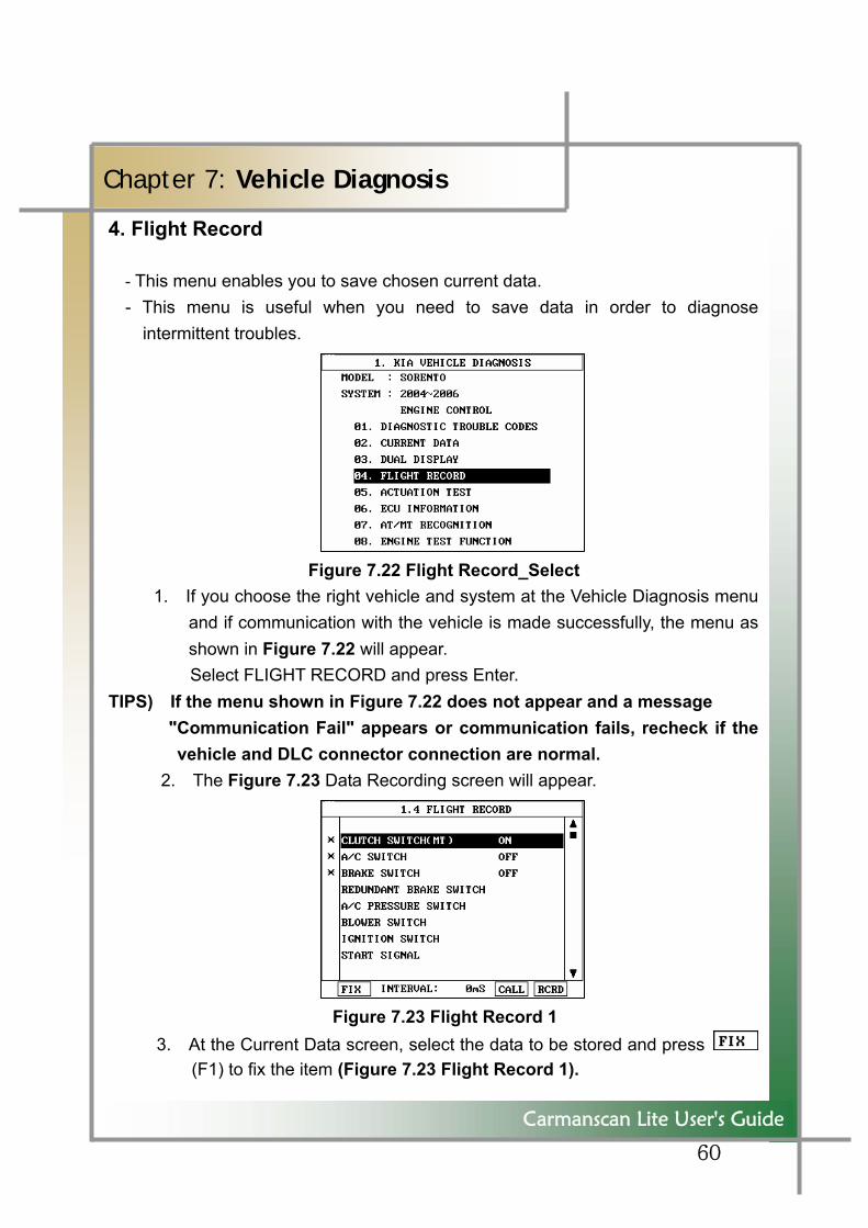
4. Flight Record
- This menu enables you to save chosen current data. - This menu is useful when you need to save data in order to diagnose
intermittent troubles.
Figure 7.22 Flight Record_Select 1. If you choose the right vehicle and system at the Vehicle Diagnosis menu
and if communication with the vehicle is made successfully, the menu as shown in Figure 7.22 will appear. Select FLIGHT RECORD and press Enter.
TIPS) If the menu shown in Figure 7.22 does not appear and a message "Communication Fail" appears or communication fails, recheck if the
vehicle and DLC connector connection are normal. 2. The Figure 7.23 Data Recording screen will appear.
Figure 7.23 Flight Record 1 3. At the Current Data screen, select the data to be stored and press
(F1) to fix the item (Figure 7.23 Flight Record 1).
61
```
Carmanscan Lite User's Guide
Chapter 7: Vehicle Diagnosis
At the side of the fixed items, * will be displayed.
TIPS) You can fix up to 8 items.
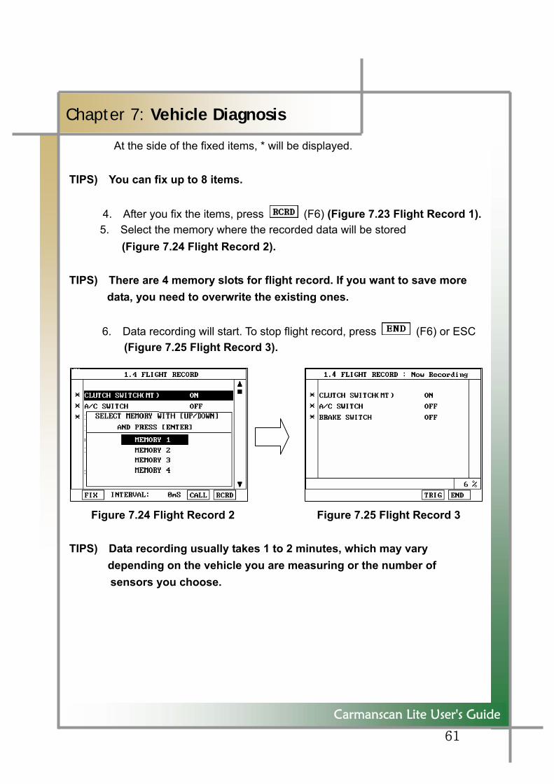
4. After you fix the items, press (F6) (Figure 7.23 Flight Record 1). 5. Select the memory where the recorded data will be stored
(Figure 7.24 Flight Record 2). TIPS) There are 4 memory slots for flight record. If you want to save more
data, you need to overwrite the existing ones. 6. Data recording will start. To stop flight record, press (F6) or ESC (Figure 7.25 Flight Record 3).
Figure 7.24 Flight Record 2 Figure 7.25 Flight Record 3
TIPS) Data recording usually takes 1 to 2 minutes, which may vary depending on the vehicle you are measuring or the number of
sensors you choose.
62
Carmanscan Lite User's Guide
Chapter 7: Vehicle Diagnosis
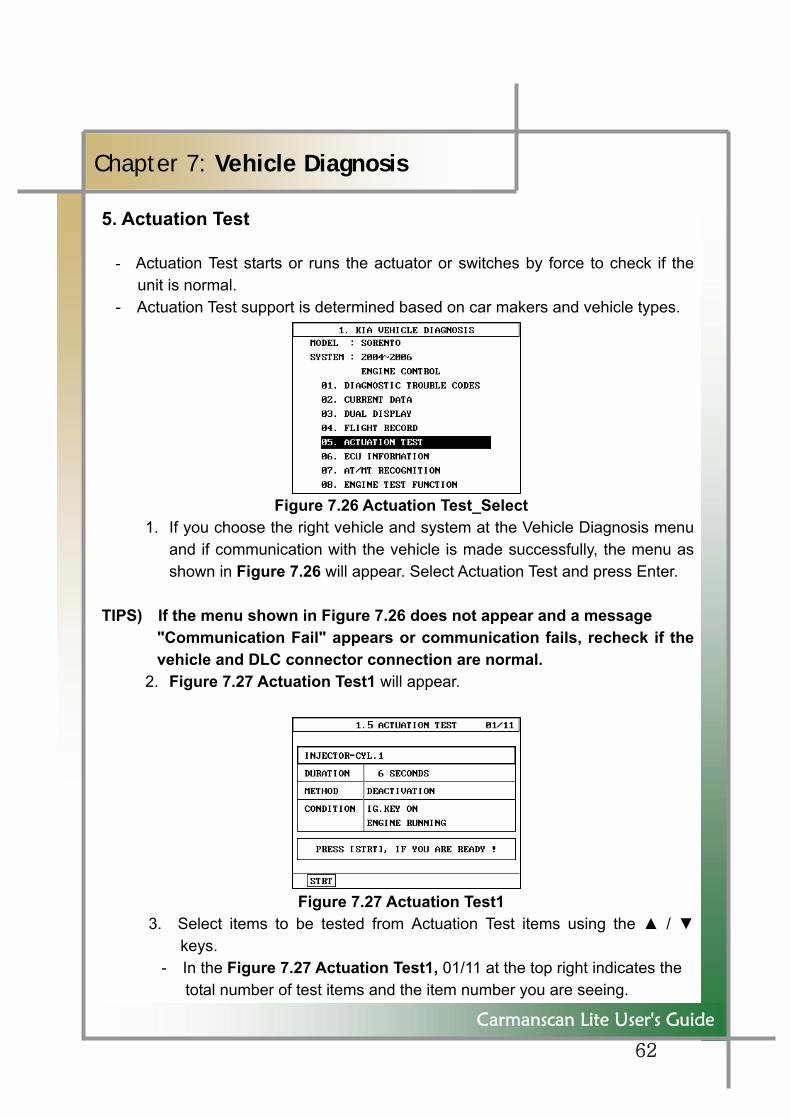
5. Actuation Test - Actuation Test starts or runs the actuator or switches by force to check if the
unit is normal. - Actuation Test support is determined based on car makers and vehicle types.
Figure 7.26 Actuation Test_Select 1. If you choose the right vehicle and system at the Vehicle Diagnosis menu
and if communication with the vehicle is made successfully, the menu as shown in Figure 7.26 will appear. Select Actuation Test and press Enter.
TIPS) If the menu shown in Figure 7.26 does not appear and a message
"Communication Fail" appears or communication fails, recheck if the vehicle and DLC connector connection are normal.
2. Figure 7.27 Actuation Test1 will appear.
Figure 7.27 Actuation Test1 3. Select items to be tested from Actuation Test items using the ▲ / ▼
keys. - In the Figure 7.27 Actuation Test1, 01/11 at the top right indicates the
total number of test items and the item number you are seeing.
63
Carmanscan Lite User's Guide
Chapter 7: Vehicle Diagnosis
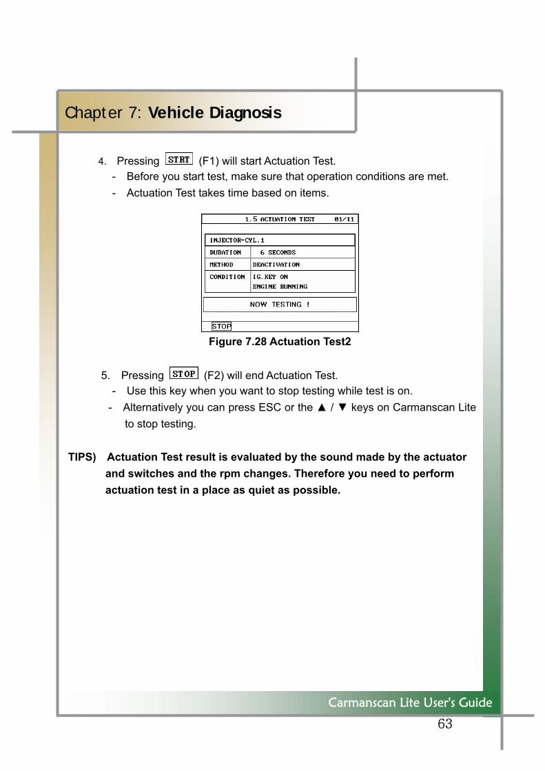
4. Pressing (F1) will start Actuation Test. - Before you start test, make sure that operation conditions are met.
- Actuation Test takes time based on items.
Figure 7.28 Actuation Test2
5. Pressing (F2) will end Actuation Test. - Use this key when you want to stop testing while test is on.
- Alternatively you can press ESC or the ▲ / ▼ keys on Carmanscan Lite to stop testing.
TIPS) Actuation Test result is evaluated by the sound made by the actuator
and switches and the rpm changes. Therefore you need to perform actuation test in a place as quiet as possible.
64
Carmanscan Lite User's Guide
Chapter 8: OBD-II Selecting Menu
1. OBD-II Overview
■ Purpose of OBD-II - OBD-II is intended to find what caused the exhaust gas to increase, diagnose the corresponding part and light the warning lamp, and thus provide faster and
more precise repair.
■ OBD-II Regulations - If exhaust gas increases due to defected parts, diagnose the part and cause,
and turn on the warning light (MIL). - Trouble information shall be read by the standard diagnosis tools (GST). ■ OBD-II Regulations《Check List 》 A warning light shall be on before the exhaust gas reaches 1.5 times of permissible limit due to the following troubles or performance degradation.
- Catalyst purification rate (diagnosis of this is for HC emission only, from TLEV
phase-in is being applied to 1.75 times of HC limit), MISFIRE, EGR System, O2 Sensor, Fuel System Secondary Air System
- Diagnose all sensors and actuators used for controlling engine to see if they are working normally and if there is no broken wire or short circuit.
- Diagnose the entire evaporation system to see if it leaks.
- Diagnose as trouble when the PCV valve and the crankcase or the PCV valve and the intake manifold are disconnected.
- Diagnose as thermostat fail when the cooler failed to reach the temperature where you can diagnose other items in a given time after starting the engine.
65
Carmanscan Lite User's Guide
Chapter 8: OBD-II Selecting Menu
2. Connecting Self Diagnosis Connector and Selecting Diagnosis Program (Common to Korean/Japanese/European vehicles)
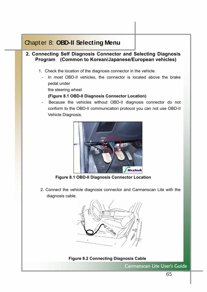
1. Check the location of the diagnosis connector in the vehicle.
- In most OBD-II vehicles, the connector is located above the brake pedal under
the steering wheel (Figure 8.1 OBD-II Diagnosis Connector Location)
- Because the vehicles without OBD-II diagnosis connector do not conform to the OBD-II communication protocol you can not use OBD-II Vehicle Diagnosis.
Figure 8.1 OBD-II Diagnosis Connector Location 2. Connect the vehicle diagnosis connector and Carmanscan Lite with the
diagnosis cable.
Figure 8.2 Connecting Diagnosis Cable
66
Carmanscan Lite User's Guide
Chapter 8: OBD-II Selecting Menu
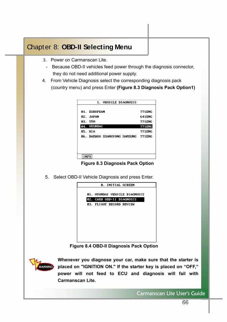
3. Power on Carmanscan Lite. - Because OBD-II vehicles feed power through the diagnosis connector,
they do not need additional power supply. 4. From Vehicle Diagnosis select the corresponding diagnosis pack
(country menu) and press Enter (Figure 8.3 Diagnosis Pack Option1)
Figure 8.3 Diagnosis Pack Option
5. Select OBD-II Vehicle Diagnosis and press Enter.
Figure 8.4 OBD-II Diagnosis Pack Option
Whenever you diagnose your car, make sure that the starter is placed on "IGNITION ON." If the starter key is placed on “OFF,” power will not feed to ECU and diagnosis will fail with Carmanscan Lite.
67
Carmanscan Lite User's Guide
Chapter 8: OBD-II Selecting Menu
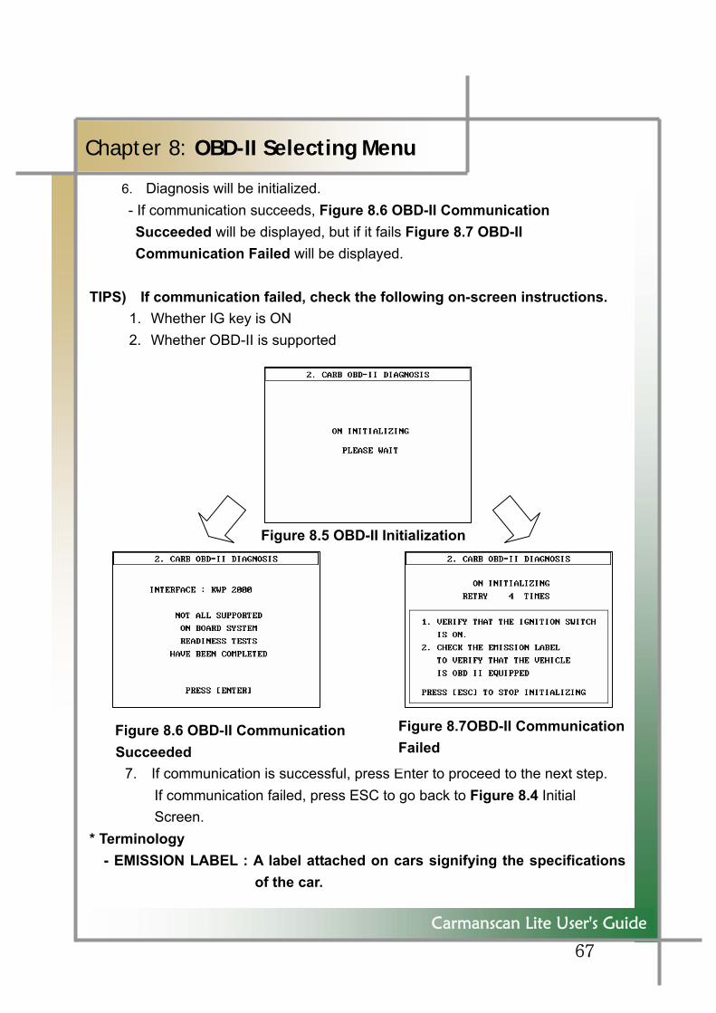
6. Diagnosis will be initialized. - If communication succeeds, Figure 8.6 OBD-II Communication Succeeded will be displayed, but if it fails Figure 8.7 OBD-II Communication Failed will be displayed.
TIPS) If communication failed, check the following on-screen instructions.
1. Whether IG key is ON 2. Whether OBD-II is supported
Figure 8.5 OBD-II Initialization
Figure 8.6 OBD-II Communication Succeeded
7. If communication is successful, press Enter to proceed to the next step. If communication failed, press ESC to go back to Figure 8.4 Initial Screen.
* Terminology - EMISSION LABEL : A label attached on cars signifying the specifications
of the car.
Figure 8.7OBD-II CommunicationFailed
68
Carmanscan Lite User's Guide
Chapter 8: OBD-II Selecting Menu
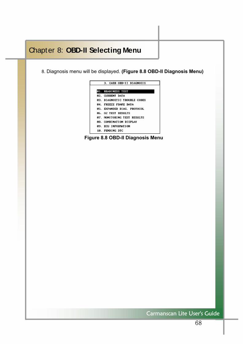
8. Diagnosis menu will be displayed. (Figure 8.8 OBD-II Diagnosis Menu)
Figure 8.8 OBD-II Diagnosis Menu
69
Carmanscan Lite User's Guide
Chapter 9: OBD-II Vehicle Diagnosis
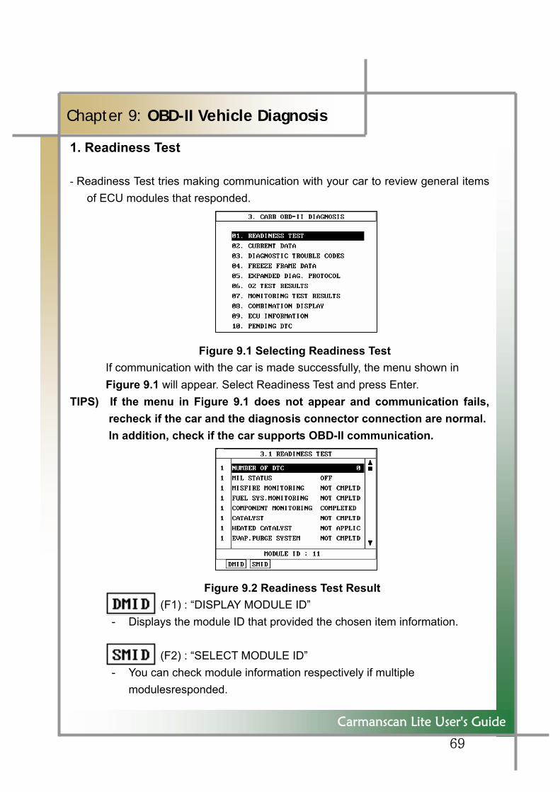
1. Readiness Test
- Readiness Test tries making communication with your car to review general items of ECU modules that responded.
Figure 9.1 Selecting Readiness Test If communication with the car is made successfully, the menu shown in Figure 9.1 will appear. Select Readiness Test and press Enter.
TIPS) If the menu in Figure 9.1 does not appear and communication fails, recheck if the car and the diagnosis connector connection are normal. In addition, check if the car supports OBD-II communication.
Figure 9.2 Readiness Test Result (F1) : “DISPLAY MODULE ID”
- Displays the module ID that provided the chosen item information.
(F2) : “SELECT MODULE ID” - You can check module information respectively if multiple
modulesresponded.
70
Carmanscan Lite User's Guide
Chapter 9: OBD-II Vehicle Diagnosis
- The number "1" displayed in the left side of the result indicates that information was acquired from one module.
- If information was acquired from more than one module, the number of modules that sent information will be displayed, and based on module information the following will be displayed in front of the module number.
* If two or more ECUs responded but the data are the same: * * If two or more ECUs responded but the data are not the same: # * If one or more ECU is supported but none responded: -
* Terminology 1. Not Completed : Test has not been completed.
- This appears when test was not completed owing to abnormal ECU or abnormal sensor required to display the result.
2. Completed : Test has been completed. 3. Off : The item is not applied to the testing vehicle.
71
Carmanscan Lite User's Guide
Chapter 9: OBD-II Vehicle Diagnosis
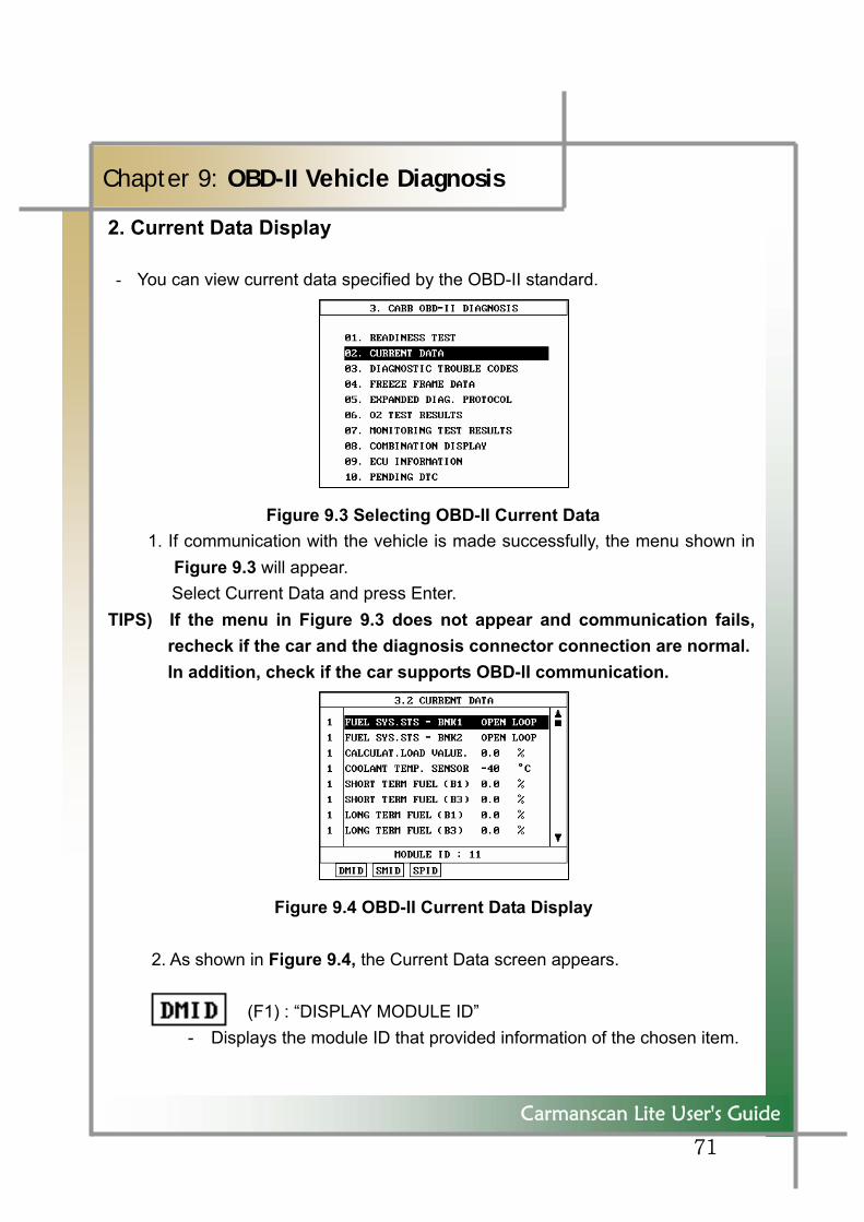
2. Current Data Display
- You can view current data specified by the OBD-II standard.
Figure 9.3 Selecting OBD-II Current Data 1. If communication with the vehicle is made successfully, the menu shown in
Figure 9.3 will appear. Select Current Data and press Enter.
TIPS) If the menu in Figure 9.3 does not appear and communication fails, recheck if the car and the diagnosis connector connection are normal. In addition, check if the car supports OBD-II communication.
Figure 9.4 OBD-II Current Data Display
2. As shown in Figure 9.4, the Current Data screen appears. (F1) : “DISPLAY MODULE ID”
- Displays the module ID that provided information of the chosen item.
72
Carmanscan Lite User's Guide
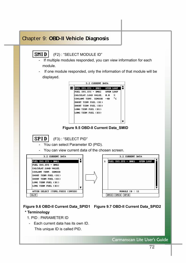
Chapter 9: OBD-II Vehicle Diagnosis
(F2) : “SELECT MODULE ID” - If multiple modules responded, you can view information for each
module. - If one module responded, only the information of that module will be
displayed.
Figure 9.5 OBD-II Current Data_SMID (F3) : “SELECT PID”
- You can select Parameter ID (PID). - You can view current data of the chosen screen.
Figure 9.6 OBD-II Current Data_SPID1 Figure 9.7 OBD-II Current Data_SPID2 * Terminology
1. PID : PARAMETER ID - Each current data has its own ID. This unique ID is called PID.
73
Carmanscan Lite User's Guide
Chapter 9: OBD-II Vehicle Diagnosis
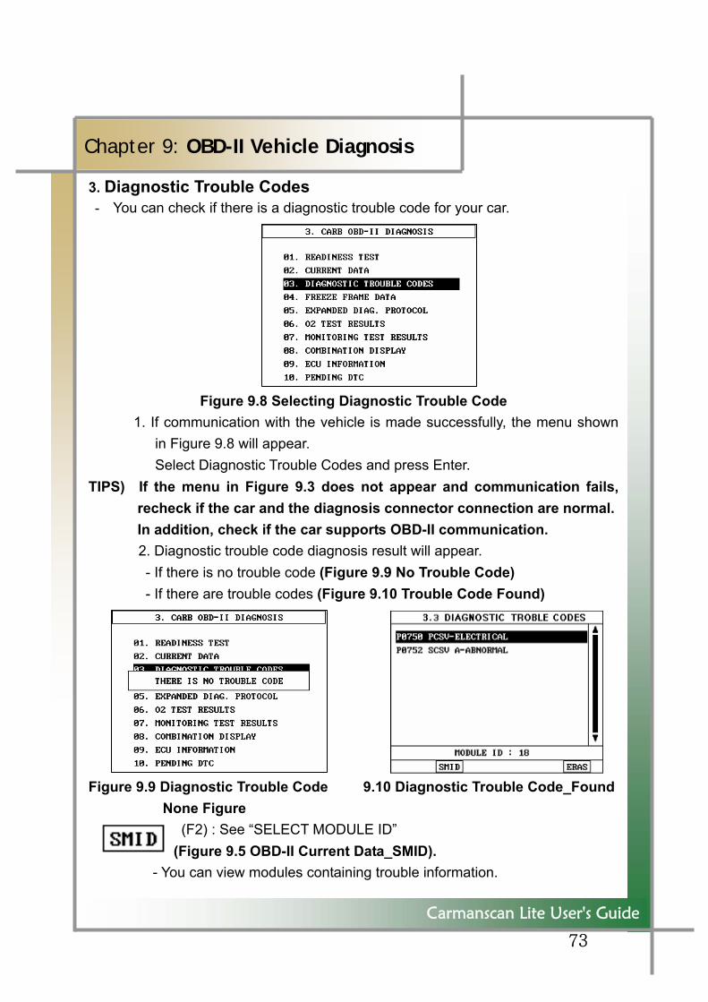
3. Diagnostic Trouble Codes - You can check if there is a diagnostic trouble code for your car.
Figure 9.8 Selecting Diagnostic Trouble Code 1. If communication with the vehicle is made successfully, the menu shown
in Figure 9.8 will appear. Select Diagnostic Trouble Codes and press Enter.
TIPS) If the menu in Figure 9.3 does not appear and communication fails, recheck if the car and the diagnosis connector connection are normal. In addition, check if the car supports OBD-II communication.
2. Diagnostic trouble code diagnosis result will appear. - If there is no trouble code (Figure 9.9 No Trouble Code) - If there are trouble codes (Figure 9.10 Trouble Code Found) Figure 9.9 Diagnostic Trouble Code 9.10 Diagnostic Trouble Code_Found
None Figure (F2) : See “SELECT MODULE ID”
(Figure 9.5 OBD-II Current Data_SMID). - You can view modules containing trouble information.
74
Carmanscan Lite User's Guide
Chapter 9: OBD-II Vehicle Diagnosis
(F6) : Erases Diagnostic Trouble Codes.
75
Carmanscan Lite User's Guide
Chapter 9: OBD-II Vehicle Diagnosis
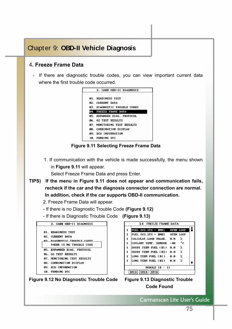
4. Freeze Frame Data
- If there are diagnostic trouble codes, you can view important current data where the first trouble code occurred.
Figure 9.11 Selecting Freeze Frame Data
1. If communication with the vehicle is made successfully, the menu shown in Figure 9.11 will appear. Select Freeze Frame Data and press Enter.
TIPS) If the menu in Figure 9.11 does not appear and communication fails, recheck if the car and the diagnosis connector connection are normal. In addition, check if the car supports OBD-II communication.
2. Freeze Frame Data will appear. - If there is no Diagnostic Trouble Code (Figure 9.12) - If there is Diagnostic Trouble Code (Figure 9.13) Figure 9.12 No Diagnostic Trouble Code Figure 9.13 Diagnostic Trouble
Code Found
76
Carmanscan Lite User's Guide
Chapter 9: OBD-II Vehicle Diagnosis
5. EDP: Expanded Diagnostic Protocol
- EDP is intended to provide the following features to enable communication by a random protocol defined by vehicle manufacturers.
(SAE J1978 Standard based OBD-II Scan Tool)
Described by Carmanscan Lite the messages transmitted to vehicles and how to transmit these messages.
Described by Carmanscan Lite the messages the scan tool will receive and process.
Described by Carmanscan Lite how to process data containing in the message received.
- Generally EDP definitions have 4 types as follows: 1) CONTROL TYPE Definition <id>,<type>,<DSV> 2) TRANSMIT TYPE Definition <id>,<type>,<tx msg>,<rx filter>, <rx data processing info>,<DSV> 3) RECEIVE ONLY TYPE Definition <id>,<type>,<rx filter>,<rx data processing info> ,<DSV> 4) MISCELLANEOUS TYPE Definition <id>,<type and additional info>,<DSV>
TIPS) For more details, see SAE J1978 Standard.
77
Carmanscan Lite User's Guide
Chapter 9: OBD-II Vehicle Diagnosis
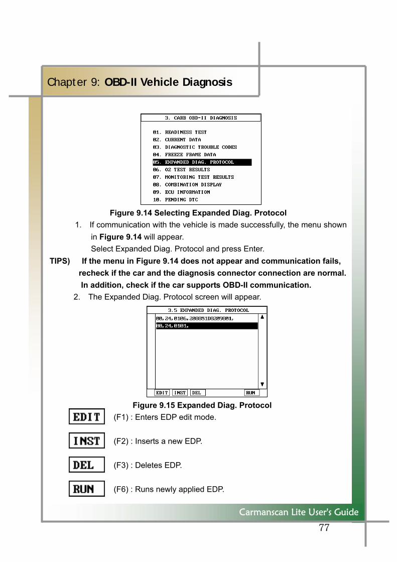
Figure 9.14 Selecting Expanded Diag. Protocol 1. If communication with the vehicle is made successfully, the menu shown
in Figure 9.14 will appear. Select Expanded Diag. Protocol and press Enter.
TIPS) If the menu in Figure 9.14 does not appear and communication fails, recheck if the car and the diagnosis connector connection are normal.
In addition, check if the car supports OBD-II communication. 2. The Expanded Diag. Protocol screen will appear.
Figure 9.15 Expanded Diag. Protocol (F1) : Enters EDP edit mode. (F2) : Inserts a new EDP. (F3) : Deletes EDP. (F6) : Runs newly applied EDP.
78
Carmanscan Lite User's Guide
Chapter 9: OBD-II Vehicle Diagnosis
Use Expanded Diagnosis Protocol only when you have professional knowledge about SAE J1978 Standard or when the car maker's standard is verified.
79
Carmanscan Lite User's Guide
Chapter 9: OBD-II Vehicle Diagnosis
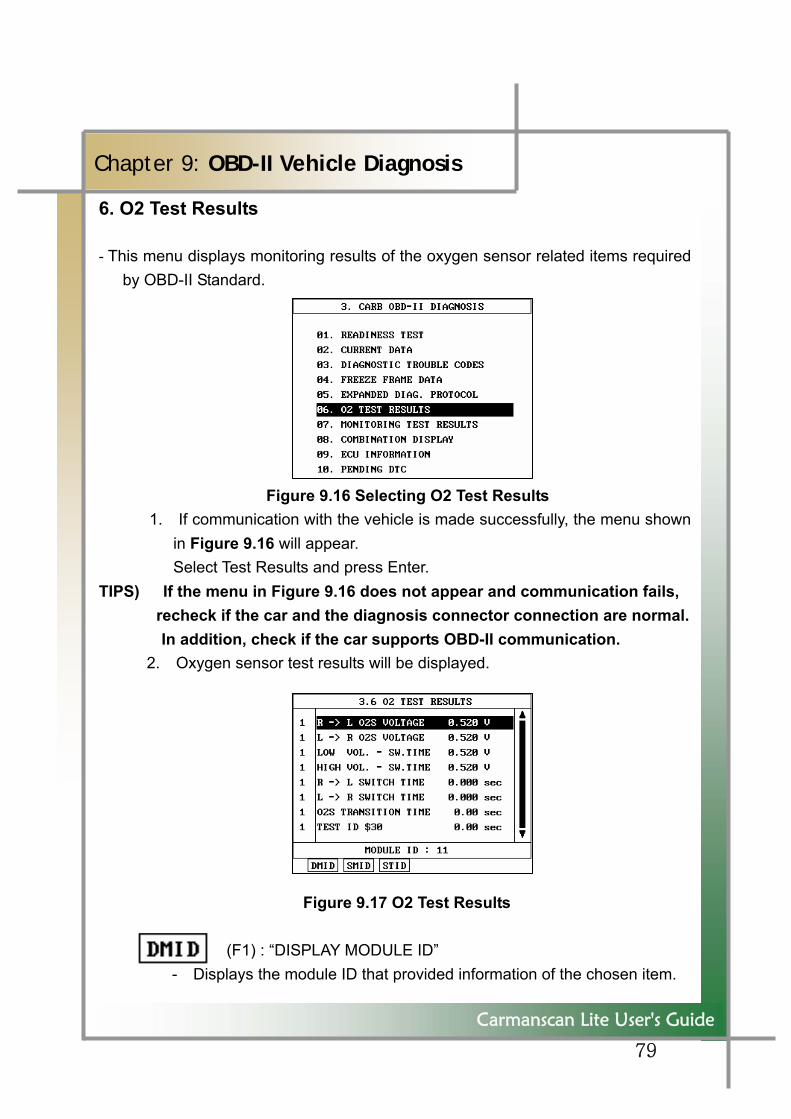
6. O2 Test Results
- This menu displays monitoring results of the oxygen sensor related items required by OBD-II Standard.
Figure 9.16 Selecting O2 Test Results 1. If communication with the vehicle is made successfully, the menu shown
in Figure 9.16 will appear. Select Test Results and press Enter.
TIPS) If the menu in Figure 9.16 does not appear and communication fails, recheck if the car and the diagnosis connector connection are normal.In addition, check if the car supports OBD-II communication.
2. Oxygen sensor test results will be displayed.
Figure 9.17 O2 Test Results (F1) : “DISPLAY MODULE ID”
- Displays the module ID that provided information of the chosen item.
80
Carmanscan Lite User's Guide
Chapter 9: OBD-II Vehicle Diagnosis
(F2) : “SELECT MODULE ID” - You can check module information respectively if multiple modules
responded. (F3) : “SELECT TEST ID” - You can select an ID you want to test.
81
Carmanscan Lite User's Guide
Chapter 9: OBD-II Vehicle Diagnosis
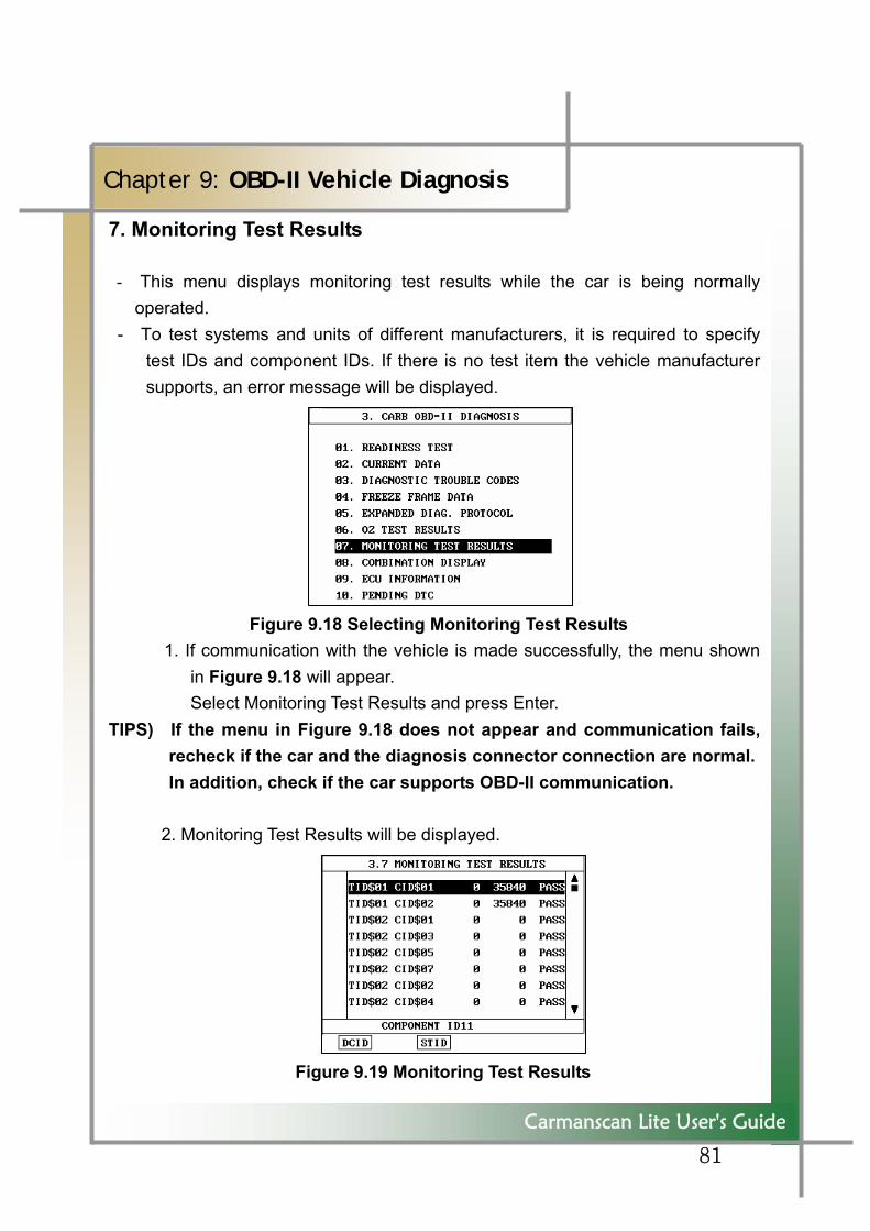
7. Monitoring Test Results
- This menu displays monitoring test results while the car is being normally operated.
- To test systems and units of different manufacturers, it is required to specify test IDs and component IDs. If there is no test item the vehicle manufacturer supports, an error message will be displayed.
Figure 9.18 Selecting Monitoring Test Results 1. If communication with the vehicle is made successfully, the menu shown
in Figure 9.18 will appear. Select Monitoring Test Results and press Enter.
TIPS) If the menu in Figure 9.18 does not appear and communication fails, recheck if the car and the diagnosis connector connection are normal. In addition, check if the car supports OBD-II communication.
2. Monitoring Test Results will be displayed.
Figure 9.19 Monitoring Test Results
82
Carmanscan Lite User's Guide
Chapter 9: OBD-II Vehicle Diagnosis
: “DISPLAY COMPONENT ID” - This is used to display the component ID you have chosen.
: “SELECT TEST ID” - You can select an ID you want to test.
83
Carmanscan Lite User's Guide
Chapter 9: OBD-II Vehicle Diagnosis
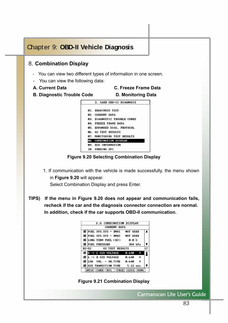
8. Combination Display
- You can view two different types of information in one screen. - You can view the following data: A. Current Data C. Freeze Frame Data B. Diagnostic Trouble Code D. Monitoring Data
Figure 9.20 Selecting Combination Display
1. If communication with the vehicle is made successfully, the menu shown in Figure 9.20 will appear. Select Combination Display and press Enter.
TIPS) If the menu in Figure 9.20 does not appear and communication fails, recheck if the car and the diagnosis connector connection are normal. In addition, check if the car supports OBD-II communication.
Figure 9.21 Combination Display
84
Carmanscan Lite User's Guide
Chapter 9: OBD-II Vehicle Diagnosis
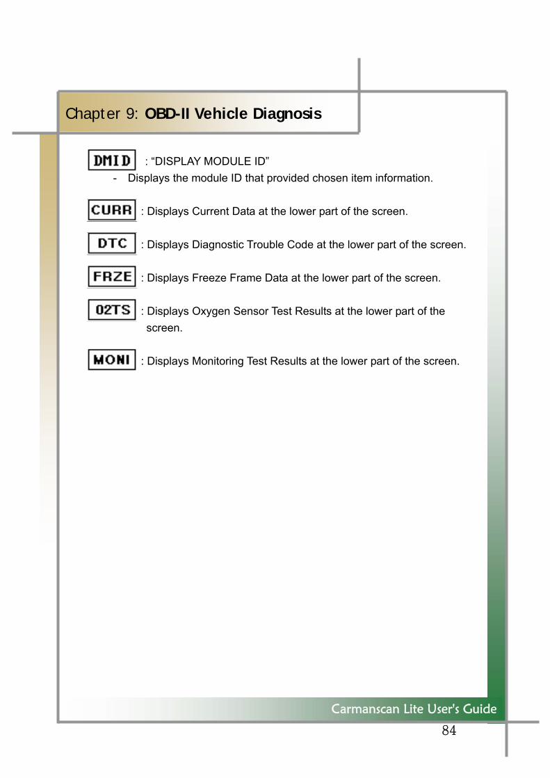
: “DISPLAY MODULE ID” - Displays the module ID that provided chosen item information.
: Displays Current Data at the lower part of the screen. : Displays Diagnostic Trouble Code at the lower part of the screen. : Displays Freeze Frame Data at the lower part of the screen. : Displays Oxygen Sensor Test Results at the lower part of the
screen. : Displays Monitoring Test Results at the lower part of the screen.
85
Carmanscan Lite User's Guide
Chapter 9: OBD-II Vehicle Diagnosis
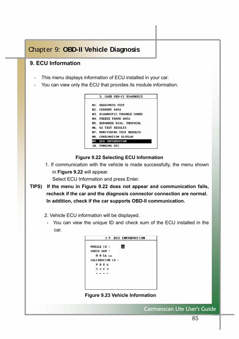
9. ECU Information
- This menu displays information of ECU installed in your car. - You can view only the ECU that provides its module information.
Figure 9.22 Selecting ECU Information 1. If communication with the vehicle is made successfully, the menu shown
in Figure 9.22 will appear. Select ECU Information and press Enter.
TIPS) If the menu in Figure 9.22 does not appear and communication fails, recheck if the car and the diagnosis connector connection are normal. In addition, check if the car supports OBD-II communication.
2. Vehicle ECU information will be displayed. - You can view the unique ID and check sum of the ECU installed in the
car.
Figure 9.23 Vehicle Information
86
Carmanscan Lite User's Guide
Chapter 9: OBD-II Vehicle Diagnosis
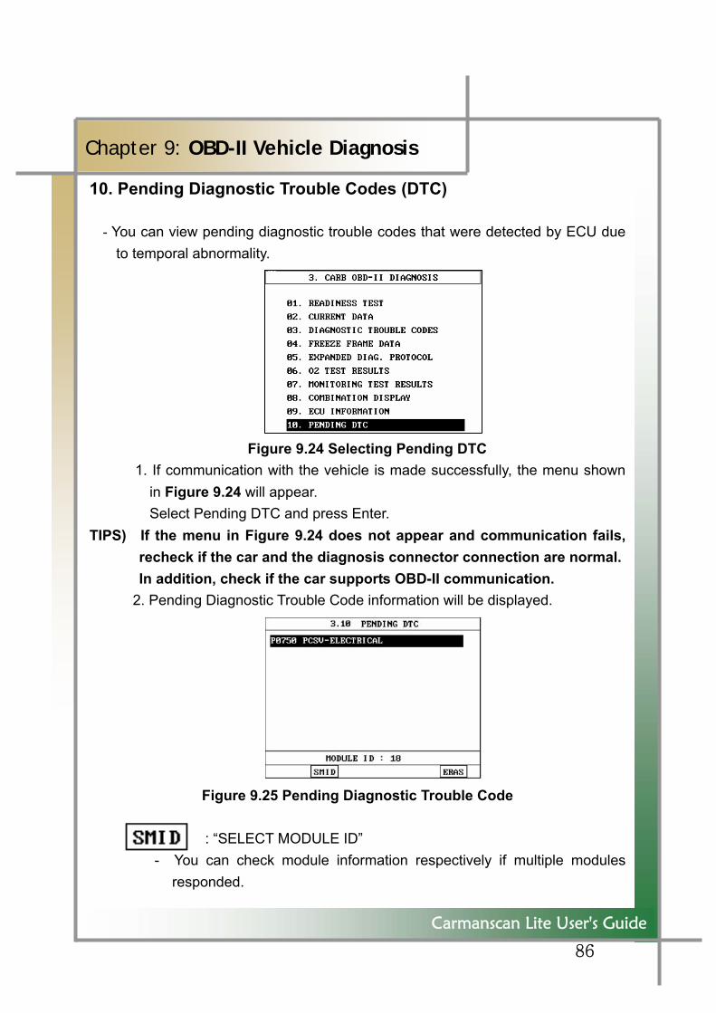
10. Pending Diagnostic Trouble Codes (DTC)
- You can view pending diagnostic trouble codes that were detected by ECU due to temporal abnormality.
Figure 9.24 Selecting Pending DTC 1. If communication with the vehicle is made successfully, the menu shown
in Figure 9.24 will appear. Select Pending DTC and press Enter.
TIPS) If the menu in Figure 9.24 does not appear and communication fails, recheck if the car and the diagnosis connector connection are normal. In addition, check if the car supports OBD-II communication.
2. Pending Diagnostic Trouble Code information will be displayed.
Figure 9.25 Pending Diagnostic Trouble Code : “SELECT MODULE ID” - You can check module information respectively if multiple modules
responded.

87
Carmanscan Lite User's Guide
Chapter 9: OBD-II Vehicle Diagnosis
: “ ERASE” - You can delete detected diagnostic trouble codes.
88
Carmanscan Lite User's Guide
Chapter 10: Flight Record Review
1. How To Feed Power
- Flight Record Review enables you to review vehicle diagnosis data stored in Carmanscan Lite whether or not it is connected to the vehicle.
Therefore, you can choose a power supply that fits environment. 1) Cigar lighter cable 2) DLC 16p cable - for OBD-II vehicles and cars that feed power through vehicle diagnosis
connector 3) AC/DC adaptor 4) Rechargeable battery pack
2. Characteristics of Flight Record Review - Previously Flight Record Review can be viewed only after you make
communication with the vehicle. But it is not possible to view without having to connect the vehicle.
3. Applications of Flight Record Review - As all types of cars provide their standard values, you can easily find troubles
by saving vehicle data at normal times and comparing them with that of problematic cars.
- For intermittent troubles or those rarely show the symptom, you can use Data Recording as a black box and view the content using Flight Record Review.
89
Carmanscan Lite User's Guide
Chapter 10: Flight Record Review
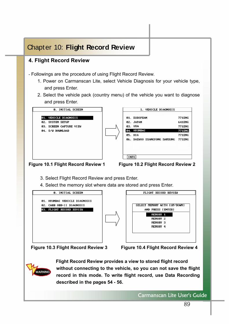
4. Flight Record Review
- Followings are the procedure of using Flight Record Review. 1. Power on Carmanscan Lite, select Vehicle Diagnosis for your vehicle type,
and press Enter. 2. Select the vehicle pack (country menu) of the vehicle you want to diagnose
and press Enter. Figure 10.1 Flight Record Review 1 Figure 10.2 Flight Record Review 2
3. Select Flight Record Review and press Enter. 4. Select the memory slot where data are stored and press Enter.
Figure 10.3 Flight Record Review 3 Figure 10.4 Flight Record Review 4
Flight Record Review provides a view to stored flight record without connecting to the vehicle, so you can not save the flight record in this mode. To write flight record, use Data Recording described in the pages 54 - 56.
90
Carmanscan Lite User's Guide
Chapter 10: Flight Record Review
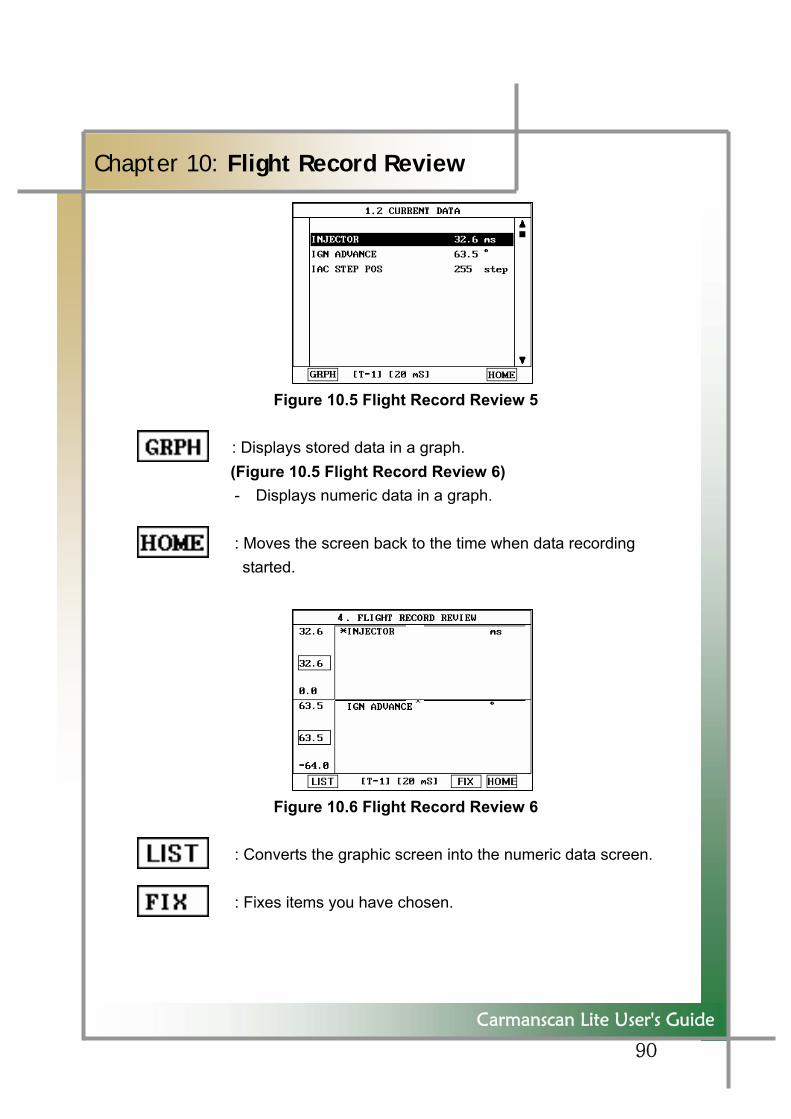
Figure 10.5 Flight Record Review 5
: Displays stored data in a graph. (Figure 10.5 Flight Record Review 6)
- Displays numeric data in a graph. : Moves the screen back to the time when data recording
started.
Figure 10.6 Flight Record Review 6 : Converts the graphic screen into the numeric data screen. : Fixes items you have chosen.

91
“
92
WARRANTY CARD Warranty Policy
1. The manufacturer warrants this product to be defect free in material and workmanship for a period of
one (1) year from the date of purchase. Defective products may be returned by the original purchaser
within the warranty period, postage pre-paid together with proof of purchase date to Nextech Co. LTD.
Defective products will be repaired at manufacturer’s discretion, replaced at no charge.
2. The warranty does not apply to any units that have been tampered with, or to damages incurred through
improper use and care, defects caused by abuse or through the usage for purposes other than the
intended use, used in a manner inconsistent with the instructions regarding use, and faulty packing or
mishandling by any common carrier.
3. Repairs not covered by this warranty will be performed at the current cost for parts and labor. In no
event will Nextech Co. Ltd’s liability exceed the price paid for the product from direct, indirect, special,
incidental or, consequential damages resulting from the use of this product, its accompanying software,
or its documentation without obligation to notify any individual or entity. Warranties hereunder extend
only to customers and are not transferable.
Warranty Period & Software update 1. Warranty period for Nextech products and these’s accessories including software card is one (1) year
from the date of sale to the original consumer.
2. Free Software update for Nextech products is one (1) year from date of purchase. After one (1) year
from purchase date, software updates will be optional and will require separate payment per request.
Repair Service 1. If you suspect that you have a problem with this product, please read the operation manual (guide)
carefully to ensure that you are operating this product properly.
2. If you conclude that a real problem exists, check your product according to the procedures on the
“Trouble Shooting Card” and mark your trial records in the blank.
3. Please return the main body or the troubled parts along with the “Trouble Shooting Card” to the repair
service center listed below. Be sure to return them in freight prepaid as we don’t accept freight collect.
Nextech Service Center North America Customer Service Center
Nextech Co. Ltd. Nextech America Inc.
E&C Venture Dream Tower(the 3rd) 13F 202 Fashion Lane suite 105
Guro-dong, 197-33 Guro-Gu, Seoul, Korea Tustin Ca, 92780 USA
Tel : (822)3140-1489 Fax : (822)3140-1449 Tel: (714)832-0100 Fax: (714)832-0123
Email : [email protected] Email: [email protected]
Website: www.nex-tech.com/carman

93
WARRANTY CARD
Warranty Registration
Upon receiving the product, please fill out the following registration form and return either by fax or
separate mail to Nextech Service Center or North America Customer Service Center (only USA
customer) according to your area.
IMPORTANT: Any delay or missing of your warranty registration may cause disadvantage or
inconvenience to your warranty repair service.
CUSTOMER NAME _____________________________________________________________
COMPANY NAME ______________________________________________________________
ADDRESS _____________________________________________________________________
COUNTRY/STATE ________________________________________ ZIP ________________
TEL NO. _____________________________ FAX NO. ______________________________
EMAIL ADDRESS _____________________________________________________________
SERIAL NO ___________________________ LOT NO ____________________________
SOFTWARE VERSION ________________________________________________________
DEALERSHIP ___________________________________________________________________
DATE OF PURCHASE MONTH ___________ DAY __________ YEAR ___________
___________________________________ _______________________________
SIGNATURE DATE
94
Carmanscan Lite User's Guide
WARNING
COPYRIGHT No part of this manual may be reproduced, stored in a retrieval system or transmitted, in any form or by any means, electronic, mechanical, photocopying, recording, or otherwise, without the prior written permission of NEXTECH.
DISCLAIMER All information, illustrations, and specifications contained in this technical instruction manual are based on the latest information available at the time of publication. The right is reserved to make changes at any time without obligation to notify any person or organization of such revisions or changes. Further, NEXTECH shall not be liable for errors contained herein or for incidental or consequential damages (including lost profits) in connection with the furnishing, performance or use of this material.
© 2008 NEXTECH Corporation. All rights reserved.