ENGLISHdocs.texatmd.com/man/TMD_MK3_DIAG_en-GB.pdf · carelessness, or inexperience, regardless of...
36
ENGLISH....................................................................5 en
Transcript of ENGLISHdocs.texatmd.com/man/TMD_MK3_DIAG_en-GB.pdf · carelessness, or inexperience, regardless of...

ENGLISH....................................................................5en

2

SUMMARY
Review of the Manual...............................................................................5INTRODUCTION......................................................................................61 ABOUT THE MANUAL........................................................................72 LEGEND OF THE SYMBOLS USED..................................................83 GLOSSARY........................................................................................94 GENERAL SAFETY REGULATIONS...............................................104.1 Glossary...............................................................................................104.2 Operator Safety Regulations................................................................10
4.2.1 General Safety Regulations......................................................................104.2.2 Risk of Asphyxiation.................................................................................104.2.3 Risk of Impact and Crushing.....................................................................104.2.4 Hazards Caused by Moving Parts............................................................114.2.5 Risk of Burning or Scalding......................................................................114.2.6 Fire and Explosion Hazard.......................................................................124.2.7 Noise Hazard............................................................................................124.2.8 High Voltage Hazard.................................................................................124.2.9 Poisoning Hazard.....................................................................................13
4.3 General User and Maintenance Warnings...........................................145 SPECIFIC SAFETY RULES FOR USING TMD MK3 DIAG..............155.1 Glossary...............................................................................................155.2 General Rules......................................................................................155.3 Operator Safety....................................................................................165.4 Device Safety.......................................................................................16
6 OPERATION OF THE RADIO DEVICES..........................................187 NORMATIVE INFORMATION...........................................................198 TMD MK3 DIAG................................................................................209 DESCRIPTION..................................................................................2110 POWER SUPPLY ..........................................................................2211 LOCATION OF THE DIAGNOSTIC SOCKET................................2312 INSTALLATION...............................................................................24
3
en

12.1 Precautions........................................................................................2412.2 Installation..........................................................................................24
13 USE.................................................................................................2914 MAINTENANCE..............................................................................3015 BLINK CODES ...............................................................................3116 TROUBLESHOOTING....................................................................3217 TECHNICAL CHARACTERISTICS.................................................3318 ENVIRONMENTAL INFORMATION...............................................3519 LEGAL NOTICES............................................................................36
4

TMD MK3 DIAG TECHNICAL MANUAL
Review of the ManualThis document is review 02 of the TMD MK3 DIAG technical manual.
5
en

INTRODUCTIONDear Customer,We would like to thank you for choosing a TEXA product for your workshop.We are certain that you will get the greatest satisfaction from it and receive agreat deal of help in your work.Please read through the instructions in this manual carefully and keep it forfuture reference.Reading and understanding the following manual will help you to avoid damageor personal injury caused by improper use of the product.TEXA S.p.A reserves the right to make any changes deemed necessary toimprove the manual for any technical or marketing requirement; the companymay do so at any time without prior notice.This product is intended to be used exclusively by technicians specialised in theAutomotive industry. Reading and understanding the information in this manualcannot replace adequate specialised training in this field.The sole purpose of the manual is to illustrate the functioning of the productsold. It is not intended to offer technical training of any kind and technicians willtherefore carry out any interventions under their own responsibility and will beaccountable for any damage or personal injury caused by negligence,carelessness, or inexperience, regardless of the fact that a TEXA S.p.A. toolhas been used following the information contained in this manual.Any additions to this manual, useful in describing the new versions of theprogram and the new functions associated to it, may be sent to you through ourTEXA technical bulletin service.This manual is to be considered an essential part of the product to which itrefers. If it is resold, the original buyer is therefore required to forward themanual to the new owner.Reproduction, partial or whole, of this manual in any form without writtenauthorisation by the manufacturer is strictly forbidden.The original manual was written in Italian, every other language is a translationof the original manual.© copyright and database rights 2015.The material contained in thisdocument is protected by the copyright and database rights. All rights reservedaccording to Law and international agreements.
6

1 ABOUT THE MANUALThis manual is divided into the following chapters:1. Legend of the symbols used in the manual: it gives indications regarding the
symbols used in this document.2. Glossary: it clears the meaning of some terms used in this document.3. General safety rules: they give important indications for the safety of the user
during workshop operations.4. Specific safety rules: they give important indications for the safety of the user,
the vehicle and of the device this document refers to.5. Operation of the radio devices: it gives important information regarding the
radio devices that are equipped on the device this document refers to.6. Regulatory information: it gives indications regarding the laws that are applied
to the device this document refers to.7. TMD MK3 DIAG: it gives a brief overview of the device this document refers to.8. Description: it describes the main features of the device this document refers to.9. Power supply: it explains how the device this document refers to is powered.10. Location of the diagnostic socket: it explains how to find the diagnostic socket
needed to connect the device this document refers to.11. Installation and configuration: it explains how to install and configure the device
this document refers to.12. Use: it explains how to use the device this document refers to.13. Maintenance: it explains how to take care of the device this document refers to.14. Blink codes: it explains how to read the flashing of the LEDs of the device this
document refers to.15. Troubleshooting: it gives some situations / problems that can occur while using
the device this document refers to, along with a possible cause and a possiblesolution.
16. Technical features: it gives the main technical features of the device thisdocument refers to.
17. Environmental information: it gives the information related to the disposal ofthe device this document refers to.
18. Legal Notices: they give information related to the manufacturer and to thewarranty that covers the device this document refers to.
7
en
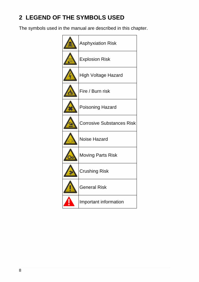
2 LEGEND OF THE SYMBOLS USEDThe symbols used in the manual are described in this chapter.
Asphyxiation Risk
Explosion Risk
High Voltage Hazard
Fire / Burn risk
Poisoning Hazard
Corrosive Substances Risk
Noise Hazard
Moving Parts Risk
Crushing Risk
General Risk
Important information
8

3 GLOSSARYThis chapter provides the meaning of the technical terms used in the manual:• Diagnosis/diagnostic socket: female connector installed in the vehicle that
allows connecting to the vehicle's control unit.• OBD socket: diagnostic socket specific for the OBD protocol.• Diagnosis/diagnostic connector: male connector installed in the diagnostic tool
or as end part of a cable that connects to the diagnostic tool.• OBD connector: diagnostic connector specific for the OBD protocol.• Diagnosis/diagnostic cable: cable that allows connecting the diagnostic cable
to the diagnostic socket.• OBD cable: diagnostic cable specific for the OBD protocol.• Display unit: device equipped with a screen (PC, PAD etc.) in which a specific
software is installed, allowing you to communicate with a tool, configure it, processand view the data it collected. This definition also includes devices that areequipped with internal modules for the acquisition and processing of data and thatdo not require / are not able to connect to "external" tools.
• Peripheral device: with respect to the display unit, any tool or device that thedisplay unit is able to interface with.
• Device connector: USB connector to connect to the device.• Host connector: USB connector to connect to the display unit.
9
en

4 GENERAL SAFETY REGULATIONS4.1 Glossary
• Operator: qualified individual, in charge of using the device/tool.• Machine/device/tool: the product purchased.• Workplace: the place where the operator must carry out her/his work.
4.2 Operator Safety Regulations
4.2.1 General Safety Regulations
• The operator must be completely clear-headed and sober when using the device;taking drugs or alcohol before or when operating the device is strictly forbidden.
• The operator must not smoke during device operation.• The operator must carefully read all the information and instructions in the
technical documents provided with the device.• The operator must follow all the instructions provided in the technical documents.• The operator must always watch over the device during the various operating
phases.• The operator must make sure she/he is working in environment which is suitable
for the operations that must be carried out.• The operator must report any faults or potentially hazardous situation in
connection with the workplace or the device.• The operator must carefully follow the safety regulations required for the
workplace in which she/he is working and required by the operations she/he hasbeen asked to carry out.
4.2.2 Risk of Asphyxiation
Exhaust gas from internal combustion engines, whether they may bepetrol or diesel, are hazardous to your health and can cause seriousharm to your body.
Safety Precautions:• The workplace must be equipped with an adeguate ventilation and air extraction
system and must be in compliance with standards according to current nationallaws.
• Always activate the air extraction system when working in closed environments.
4.2.3 Risk of Impact and Crushing
The vehicles which are undergoing A/C system recharging operationsand the devices, must be properly blocked using the specificmechanical brakes/blocks, while being service.
10

Safety Precautions:• Always make sure that the vehicle is in neutral gear (or that it is set in parking
position in case of a vehicle equipped with automatic transmission).• Always activate the hand brake or parking brake on the vehicle.• Always block the wheels on the vehicle with the specific mechanical blocks.• Make sure the device is stable, on a flat surface and the wheels are locked with
the specific brakes.
4.2.4 Hazards Caused by Moving Parts
Vehicle engines include parts that move, both while running and notrunning (eg: the cooling fan is controlled by a thermal switch inconnection with the coolant temperature and become activated evenwhen the vehicle is off), that can injure the operator.
Safety Precautions:• Keep hands away from moving parts.• Disconnect the engine cooling fan each time the engine you are working on is still
hot. This will avoid the fan from becoming activated unexpectedly even when theengine is off.
• Do not wear ties, loose clothes, wrist jewellery or watches when working on avehicle.
• Keep connection cables, probes and similar devices away from the moving partsof the engine.
4.2.5 Risk of Burning or Scalding
The parts that are exposed to high temperatures in engines that aremoving or have just stopped could burn the operator.Remember that catalytic mufflers reach very high temperatures, ableto cause serious burns or even start fires.Acid in the vehicle batteries is another potential hazard.
Safety Precautions:• Protect your face, hands, and feet by using suitable protection.• Avoid contact with hot surfaces, such as spark plugs, exhaust pipes, radiators
and connections within the cooling system.• Make sure there are no oil stains, rags, paper or other inflammable material near
the muffler.• Avoid splashing electrolyte on skin, eyes and clothes, as it is a corrosive and
highly toxic compound.
11
en

4.2.6 Fire and Explosion Hazard
The following are potential fires and/or explosion hazards:• The types of fuel used by the vehicle and the vapours released by these
fuels.• The refrigerants used by the A/C system.• The acid in the vehicle batteries.
Safety Precautions:• Let the engine cool.• Do NOT smoke near the vehicle.• Do NOT expose the vehicle to open flames.• Make sure that the electrical connections are all well insulated.• Collect any fuel that might have spilled.• Collect any refrigerant that might have spilled.• Make sure you are always working in an environment equipped with a good
ventilation and air extraction system.• Always activate the air extraction system when working in closed environments.• Cover the openings of the batteries with a wet cloth in order to stifle the explosive
gases before proceeding in testing or recharging.• Avoid causing sparks when connecting cables to the battery.
4.2.7 Noise Hazard
Loud noises that may occur within the workplace, especially duringservice operations may damage the operator's hearing.
Safety Precautions:• Protect your ears with suitable protective ear wear.
4.2.8 High Voltage Hazard
The voltage supply from the mains that powers the devices in theworkplace and the voltage within the vehicle starter system is apotential shock hazard to the operator.
Safety Precautions:• Make sure the electrical system in the workplace is compliant to current national
standards.• Make sure the device being used is connected to ground.• Cut off the power supply voltage before connecting or disconnecting cables.• Do NOT touch the high voltage cables when the engine is on.• Operate in conditions of insulation from ground.12

• Work with dry hands only.• Keep conductive liquids away from the engine while working.• Never leave tools on the battery in order to avoid accidental contacts.
4.2.9 Poisoning Hazard
The hoses used to extract the refrigerants can release toxic gases,dangerous to the operator if exposed to temperatures higher than 250°C or in case of a fire.
Safety Precautions:• Contact a doctor immediately should you inhale these gases.• Use neoprene or PVC gloves when eliminating combustion deposits.
13
en

4.3 General User and Maintenance Warnings
When using the device or carrying out scheduled maintenance (eg. fusereplacement) on the device, carefully follow the information provided below.• Do not remove or damage the labels/tags and the warnings on the device; do
NOT in any case make them illegible.• Do not remove, or block, any safety devices the device is equipped with.• Only use original spare parts or spare parts approved by the manufacturer.• Contact your retailer for any non-scheduled maintenance.• Periodically check the electrical connections of the device, making sure they are
in good condition and replacing any damaged cables.• Check parts that are subject to wear periodically and replace if necessary.• Do not open or disassemble the device.
14

5 SPECIFIC SAFETY RULES FOR USING TMD MK3 DIAGThe technology used in the design and production inspections of TMD MK3DIAG diagnostic tools means that they are reliable, simple and safe to use.Personnel in charge of using diagnostic tools are required to follow the generalsafety regulations, to use TMD MK3 DIAG devices for their intended use only,and to carry out maintenance correctly as described in this manual.
5.1 Glossary
Operator: qualified individual in charge of using the diagnostic tool.Tool/device: any TMD MK3 DIAG device.
5.2 General Rules
• The operator must have basic knowledge of mechanics, automotive engineering,car repair and of the potential dangers that may arise during self-diagnosisoperations.
• The operator must carefully read and understand the information and theinstructions in the technical documents provided with the device.
15
en

5.3 Operator Safety
Some self-diagnosis operations allow you to activate/deactivate certainactuators and safety systems on the vehicle.
Safety Measures:• In order to avoid injuring people and/or damaging the device or the electronic
systems of the vehicle connected to the device, do not allow unqualified personnelto use the device.
• Follow the instructions supplied by the software thoroughly.
5.4 Device Safety
The device was designed to be used in specific environmentalconditions.Using the device in environments with temperatures and humidity thatdiffer from those specified, may impair its efficiency.
Safety Measures:• Always place the device in a dry area.• Do not expose or use the device close to heat sources.• Place the tool making sure it can be properly ventilated.• Do not use corrosive chemicals, solvents or harsh detergents to clean the device.
The tool was designed to be mechanically tough and suitable for usein a workshop.Careless use and excessive mechanical strain may impair itsefficiency.
Safety Measures:• Do not drop, shake or knock the device.• Do not carry out any type of intervention that may damage the device.• Do not open or disassemble the device.• Make sure not to damage the diagnostic connectors when connecting and
disconnecting the device.
The device was manufactured to be electrically safe and to work withspecific supply voltage levels.Failure to comply with the specifications related to the power supplymay impair the device's efficiency.
Safety Measures:• Do not wet the device with water or other liquids.
16

• If not otherwise specified, use the tool on vehicles with a 12 V DC power supplyand chassis connected to the negative pole.
• Do not use external batteries to supply the tool unless explicitly requested to doso by the software.
The electromagnetic compatibility tests carried out on the deviceguarantee that it can be adapted to the technologies normally used onvehicles (ex.: engine control, ABS, airbag, etc.). Nevertheless, ifmalfunctions occur, contact the vehicle's dealer.
17
en

6 OPERATION OF THE RADIO DEVICESWireless connection with Bluetooth® technology
The wireless connection with Bluetooth technology is a technology that suppliesa standard and reliable method to exchange information between differentdevices, using radio waves. Products such as cellular phones, portable devices,computers, printers, cameras, pocket PCs etc. use this type of technology.The Bluetooth interface searches for compatible electronic devices accordingto the radio signal they generate and establishes a connection between them.The tools operate a selection suggesting only compatible / enabled devices.This does not exclude the presence of other sources of communication orinterference.THE EFFICIENCY AND THE QUALITY OF THE BLUETOOTHCOMMUNICATION MAY BE INFLUENCED BY THE PRESENCE OF RADIODISTURBANCE SOURCES. THE COMMUNICATION PROTOCOL HASBEEN DEVELOPED TO MANAGE THESE TYPES OF ERRORS; HOWEVER,IN THESE CASES COMMUNICATION MAY BECOME DIFFICULT ANDCONNECTION MAY REQUIRE SEVERAL ATTEMPTS.SHOULD THE WIRELESS CONNECTION ENCOUNTER SERIOUSPROBLEMS THAT MAY COMPROMISE A REGULAR COMMUNICATION,THE SOURCE OF THE ENVIRONMENTAL ELECTROMAGNETICINTERFERENCE MUST BE IDENTIFIED AND ITS INTENSITY REDUCED.Position the product in order to guarantee the correct operation of its radiodevices. In particular, do not cover it with any shielding or metal materials ingeneral.
18

7 NORMATIVE INFORMATIONDeclaration of Conformity
Texa S.p.A. hereby declares that this TMD MK3 DIAG device complieswith the essential requirements and with all further provisions definedby the R&TTE 1999/5/EC and RoHS 2011/65/EU directives.
A complete copy of the Declaration of Conformity can be found atTexa S.p.A., Via 1 Maggio 9, 31050 Monastier di Treviso (TV), Italy
19
en

8 TMD MK3 DIAGTMD MK3 DIAG is a small device capable of acquiring data while driving viathe vehicle OBD socket on which it is installed.
Connecting the TMD MK3 DIAG and disconnecting it from the vehicle is quickand easy.Because of its small size, the device takes up little space and does not interferewith driving.TMD MK3 DIAG acts as a gateway between vehicle diagnosis resources andexternal devices capable of using this diagnosis data.To do so it communicates with a tracking device via Bluetooth and transmits theacquired data.Using the TMD MK3 DIAG with a remote diagnosis device of the TMD seriesallows you to combine diagnosis functions with GPS tracking functions.
20

9 DESCRIPTIONThis chapter describes the general features of the device.
1. Status LEDs: they give indications regarding the status of the device.*• Green: indicates the status of the device without Bluetooth communication.• Red: indicates the presence of errors.
2. Extraction hook: it allows you to remove the device easily.3. Retention hook: it secures the device to the vehicle's diagnostic socket.4. Connector for assistance activities: it allows you to carry out assistance
activities on the device.5. OBD connector: it allows the connection between the device and the vehicle's
diagnostic socket and, through the latter, to the control unit.
(*) For more information consult the chapter Blink Codes.NOTE:The Bluetooth antenna is integrated within the device and is not accessible fromoutside.
21
en
10 POWER SUPPLYThe device is designed to be used ONLY on vehicles with 12 V power supplyand chassis connected to the negative pole.The device draws its power supply directly from the battery of the vehicle it isconnected to through the OBD socket.
Do not supply the device using external batteries or through sourcesthat differ from those specified in this manual.The vehicle's OBD socket is always powered, even when the engine andinstrument panel are off.The absorption never affects the battery's charge, however you shoulddisconnect the device from the vehicle's OBD socket if the vehicle is notused for a long period of time.
22
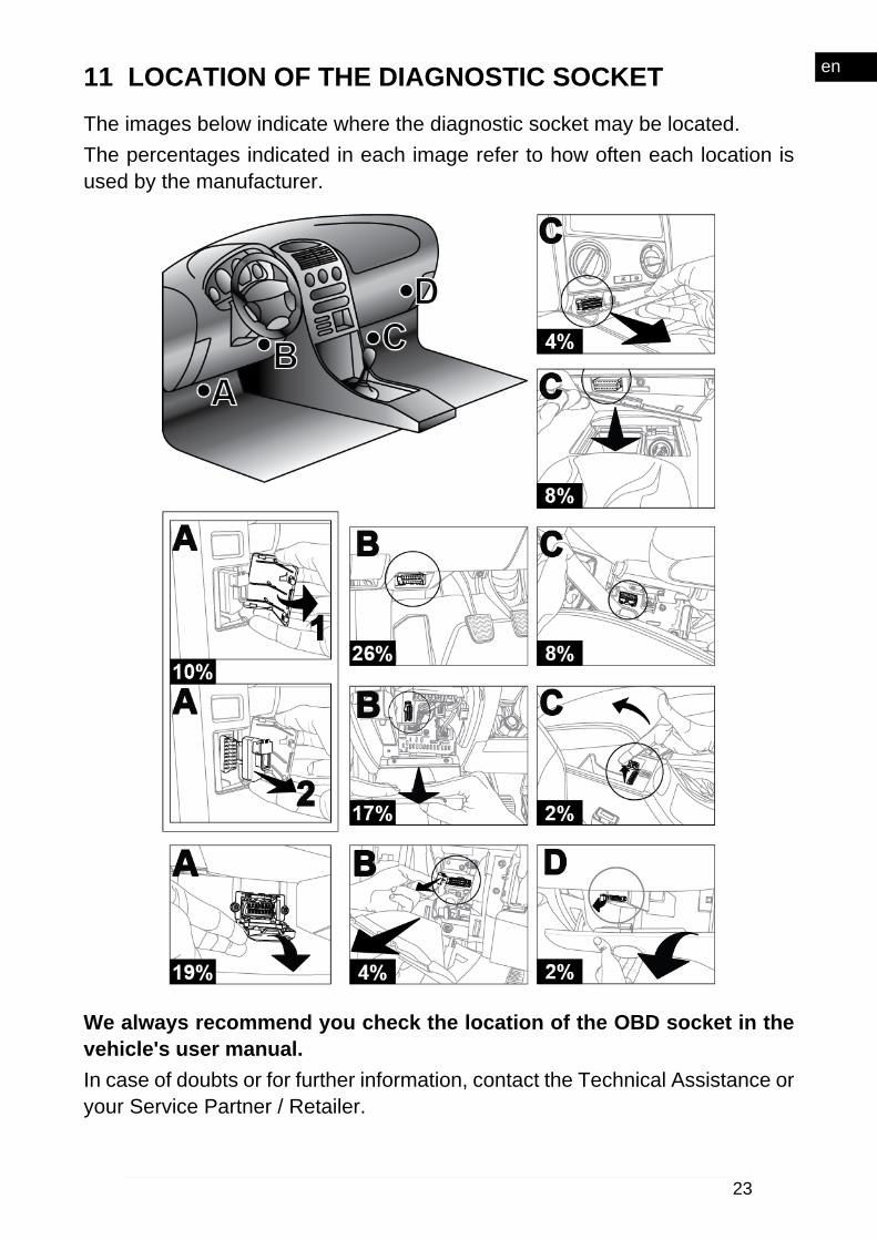
11 LOCATION OF THE DIAGNOSTIC SOCKETThe images below indicate where the diagnostic socket may be located.The percentages indicated in each image refer to how often each location isused by the manufacturer.
We always recommend you check the location of the OBD socket in thevehicle's user manual.In case of doubts or for further information, contact the Technical Assistance oryour Service Partner / Retailer.
23
en

12 INSTALLATIONThe following chapters illustrate how to install the device.
The installation must be performed by qualified personnel only.
12.1 Precautions
Make sure that all wirings and cables in general and the hydraulicpipes of both fuel and safety pneumatic devices do not suffer from anydamage during installation.
Make sure that the installation does not affect the operation of thevehicle's controls, such as brakes, steering wheel and, in general, allsafety devices.
During the installation, make sure the various components aroundthe OBD diagnostic socket do not damage the device.
Make sure that the position of the device does not interfere withdriving.
12.2 Installation
The device is equipped with a string that allows it to be fastened securely andprevents it from getting lost.
1. Device2. String3. Terminal
24

A screwdriver may be needed to loosen the screws that fasten thepanels that cover the OBD socket.
Make sure the vehicle is off (instrument panel off) when connectingand disconnecting the device from the OBD socket.Proceed as follows:1. Turn off the vehicle (ignition key off).2. Locate the OBD socket.3. Carefully remove any panels cover the OBD socket.4. Connect the device to the OBD socket.
Make sure that the various components around the diagnosticsocket do not damage the device during installation.
5. Check to see if there is a screw anywhere near the OBD socket with a smallenough diameter to allow it to pass through the cable eyelet.6. If there is no screw that serves this purpose, find a place where you can makea hole with the self-drilling screw.7. Fasten the eyelet terminal with the screw.8. Pull the string and shorten it as much as possible, leaving it only long enoughso that you will be able to remove the device from the OBD socket in the future.
25
en

Choose the length of the string carefully, based on the position ofthe OBD socket. Make sure it does not interfere with the use of the clutch,brake or accelerator or other devices within the vehicle required for safetyreasons or a normal operation of the vehicle itself, as specified by the carmanufacturer.9. Tie the string just before the eyelet terminal.
10. Cut the extra string after the knot.
26

11. Make sure the device is securely connected to the diagnostic socket to avoidit from accidentally disconnecting during use.12. Turn on the vehicle (instrument panel on).13. Wait for the LED to flash.
Make sure that the position of the device does not interfere withdriving.14. Reposition and fasten the panels removed during the installation.In some cases the device may remain in sight.
Do not be distracted by the device and check the status of the devicewhile driving.
27
en

NOTE: Device removalYou might have to disconnect the device form the OBD socket during vehiclemaintenance operations in order to allow the connection of diagnostic devices.Proceed as follows:1. Turn off the vehicle (ignition key off).2. Carefully remove any panels cover the OBD socket.3. Lift the extraction hook,4. Carefully pull out the device until it disconnects completely from thediagnostic socket.
Do not use screwdrivers or other tools to lever and disconnect thedevice.
28

13 USEIt is no longer required to act directly on the device after the installation andconfiguration.The device activates as soon as the vehicle's instrument panel is switched on.
While driving, do not get distracted to check the status of the deviceor to interact with it directly or indirectly.In case of doubts or for further information, contact the Technical Assistance oryour Service Partner / Retailer.
29
en

14 MAINTENANCEThis product does not require maintenance operations.Follow the indications in this manual carefully in order to guarantee an extendeduse of the device.In case of doubts or for further information, contact the Technical Assistance oryour Service Partner / Retailer.
30

15 BLINK CODESThe bi-colour LED (green/red) on the device flashes to indicate the variousstates of the device itself, both while it is connecting to the display unit and whenit is connecting to the vehicle.The BLINK CODE of the LED is indicated in the table below.
LEDDURATION STATUS
GREEN RED1 flash every 5seconds Off Undefined Device connected to the PC
Off Off Undefined Device ready to start the trip
On Off 5 min.Beginning of tripacknowledged, waiting forcommands.
3 flashes every 2seconds Off Undefined
Device connected to thevehicle, data acquisition inprogress
Off Quick flashing 60 seconds
Device connected to thevehicleDevice NOT activated or NOTconfigured or generic error
NOTE:Start of trip: engine is turned on.
31
en

16 TROUBLESHOOTINGBelow there are some situations / problems that can occur while using thedevice, along with a possible cause and a possible solution.
Situation / Problem Possible Cause Possible Solution
The engine is on, but thegreen LED is not turningon.
The device is notproperly connected andappears as switched off.
Carefully disconnect andreconnect the device tothe diagnostic socketmaking sure it is insertedsecurely.
The vehicle's diagnosticsocket is damaged.
Contact an authorisedworkshop.
The red LED flashesrapidly.
Device NOT activated orNOT configured orgeneric error
Contact TechnicalAssistance.
32

17 TECHNICAL CHARACTERISTICS
Manufacturer: TEXA S.p.A.Model: TMD MK3 DIAGMicrocontrollerCore ARM CORTEX M4 168 MHz
Memory • Total Flash: 256 MByte NAND FLASH• Total RAM: 8 MByte SDRAM
Operating statuswarnings
• 1 green LED• 1 red LED
Vehicle interface Standard OBD socketProcessing unitinterface Bluetooth Classic (2.1) and 4.0 Low Energy (Smart Ready)
EOBDcompatibility
Complete electrical and mechanical compatibility asdefines by the ISO 15031-03 OBD plug standard
Supportedprotocols
Complete compatibility as defined by the standards:• K, L (with 60 mA current protection) ISO9141-2, ISO14230• CAN HS ISO11898-2• CAN LS ISO11898-3
Power Supply Supports 12 V vehicles
Consumption
• vehicle ON:• absorption with TMD MK3 DIAG only = 80 mA• maximum absorption (with TMD MK3 EDR connected
to the J3 connector) = 450 mA• vehicle OFF: 3 mA
Operatingtemperature - 20 °C ÷ 60 °C
Storagetemperature - 30 °C ÷ 70 °C
Dimensions
Weight 20 g
33
en

Directives R&TTE 1999/05/ECRoHS 2011/65/EU
Productstandards
EN 301 489-1V1.9.2:2011EN 301 489-17V1.6.1:2013EN 300 328-2V1.8.1:2012EN 60950-1:2006 + A11:2009 + A1:2010 + A12:2011 + AC:2011 + A2:2013ISO 7637-1:2002ISO 7637-2:2011
Regulations ECE / ONU R10
34

18 ENVIRONMENTAL INFORMATION
For information regarding the disposal of this product please seethe pamphlet supplied.
35
en

19 LEGAL NOTICESTEXA S.p.A.Via 1 Maggio, 9 - 31050 Monastier di Treviso - ITALYCod. Fisc. - No. of Companies' Register of Treviso - Part. IVA: 02413550266Single member company and subject to management and co-ordination ofOpera Holding S.r.l.Share capital of 1.000.000 € i.v. - R.E.A. N. 208102Legal Representative Bruno VianelloPhone +39 0422.791.311Fax +39 0422.791.300www.texa.com
For information regarding the legal notices, please refer to InternationalWarranty Booklet provided with the product in your possession.
36