CARE INO III 3D IN 2D PLANAR DISPLAY PROJECT D4-1: … · Disadvantages; 1. Cluttered flight deck...
28
CARE INO III 3D IN 2D PLANAR DISPLAY PROJECT D4-1: REVIEW OF COCKPIT DISPLAYS DESIGN (LOT NO. 3, WP 4) Reference : Edition 1 Effective Date 6/10/08 Authors Organisation Signature Colin Stephens British Airways Mark Seymour British Airways
Transcript of CARE INO III 3D IN 2D PLANAR DISPLAY PROJECT D4-1: … · Disadvantages; 1. Cluttered flight deck...

CARE INO III
3D IN 2D PLANAR DISPLAY PROJECT
D4-1: REVIEW OF COCKPIT DISPLAYS DESIGN
(LOT NO. 3, WP 4)
Reference : Edition 1 Effective Date 6/10/08
Authors Organisation Signature
Colin Stephens British Airways
Mark Seymour British Airways

D4-1 final Page II Effective Date : 06/10/08
DOCUMENT CONTROL
Copyright notice
© 2008 European Organisation for the Safety of Air Navigation (EUROCONTROL). All rights reserved. No part of this publication may be reproduced, stored in a retrieval system, or transmitted in any form or by any means, electronic, mechanical, photocopying, recording or otherwise, without the prior written permission of EUROCONTROL.
Edition history
Edition
Nº
Effective date
or status
Author(s) Reason
1 6/10/2008 Stevens and
Seymour
Deliverable due.
Acknowledgements
Name Location
Members of the project team
William Wong Middlesex University
Fan Han Middlesex University
Stephen Gaukrodger Middlesex University
Paola Amaldi Middlesex University
Bob Fields Middlesex University
Martin Loomes Middlesex University
Ifan Shepherd Middlesex University
Richard Aked Space Applications Services
Luigi Mazzuchelli NEXT Sistemi Ingeneria

06/10/08 Page 3
D4-1 final
Table of Contents
1. INTRODUCTION................................................................................................... 4
2. FLIGHT INSTRUMENTATION OF THE 1970S .................................................... 5
3. FLIGHT INSTRUMENTATION OF 1980S ............................................................ 7
4. CURRENT INSTRUMENTATION DISPLAYS ...................................................... 9
5. NEXT GENERATION DISPLAYS ....................................................................... 16
6. FUTURE DISPLAY SOLUTIONS: ...................................................................... 24
7. CONCLUSIONS ................................................................................................. 27
8. REFERENCES ................................................................................................... 28

06/10/08 Page 4
D4-1 final
1. INTRODUCTION
The aim of this report is to discuss current commercial aeroplane flight instrumentation and
propose future directions for research into improvements in instrumentation design.
The scope of this report is limited to commercial fixed-wing aeroplanes. The report will look
at the early development of flight instruments, the implementation on 1970s and 1980s
vintage aeroplanes, the current generation of displays, the next generation due to enter or in
the process of entering service and finally ideas and considerations for future designs.
Background:
Early in the days of fixed wing aviation it was realised that the use of aeroplanes was
severely limited by weather and geography. Essentially, some form of instrumentation was
required to enable pilots to fly in limited visual conditions (in cloud and at night) and to
navigate. It was also recognised that several parameters were essential to be displayed to
the pilot; airspeed, altitude and direction of flight. The format of the instrumentation was
guided by limited gains in technology and incremental changes to similar instrumentation
used in other industries at the time. Although many variations of instrument layouts were
used, the most common flight instrument layout was the standard “T” layout. Figure 1 shows
an example of the layout.
Figure 1. Standard “T” layout of flight instruments
In the “T” format, a gyroscopic presentation of aeroplane attitude formed the focal point of
the “T”. To the left was the aeroplane airspeed, to the right altitude, and below gyroscopic
direction. Also displayed was vertical speed and turn and slip information.

06/10/08 Page 5
D4-1 final
During the years following the Second World War, there was a progressive increase in the
number of instruments and associated complexity of information displayed to the flight crew.
It should be remembered that one of the prime drivers for what and how information was
displayed, was what was achievable. The size and shape of the displays and the type of
information shown was limited by technology of the time. There was little research into how
data should be displayed and many ideas carried over from other industries with the
assumption that they would be satisfactory. In many ways, this remains the case.
The advantage of the “T” format was that it enabled the pilot, who was manually flying the
aeroplane, to concentrate primarily on the major performance indicator - the attitude
indicator (or artificial horizon) and scan out and back to the secondary instruments, such as
the speed and altitude.
Advantages;
1. Any display is better than none, when flying without visual reference!
2. Aviation was a small industry and the adoption of a standard early on made
conversion to other aircraft easier.
3. It was realized that the aeroplane attitude was the critical parameter, empirically,
which simplified many aspects of pilot training.
Disadvantages;
1. With only a few instruments and therefore limited information, the type of display was
a lower priority.
2. The speed of the aircraft and the complexity of the task required of the pilot left
sufficient time to “process” information. As a consequence, not a lot of thought was
required to optimise the display format or type of symbology.
3. As aeroplanes became more complex the addition of more and more instruments
meant that a complete standard was no longer possible. However, the “T” remained
in common use until the current generation of designs. Indeed, even the introduction
of modern designs has left the legacy of the “T” which can be seen in the integrated
displays on aeroplanes such as the B777.
2. FLIGHT INSTRUMENTATION OF THE 1970S
In general pilots are very conservative and often dislike changes. Indeed the preferred
psychological profile on a Meyers – Briggs scale is ENTJ i.e. outgoing, conservative, data
driven and leaders. These are the criteria upon which they are selected by most major

06/10/08 Page 6
D4-1 final
airlines and have been for many years. Military and commercial pilots since the early days of
aviation tend to be rule based and like structure. They have a preference for facts and treat
solutions to events as black and white. Since pilots form the backbone of the flight
operations departments of the regulatory authorities it should come as no surprise that they
too are very conservative and reluctant to adopt changes without sound justification. Any
such change when it does come along is accepted at a very slow pace. Firstly changes have
to be proven to be worthwhile and safe and then to deliver a clear benefit before they will be
adopted.
Air transport operations were not considered sufficiently demanding to require advanced
equipment like electronic flight displays even though the hardware was readily available and
in common use with the military fixed wing aeroplanes. Also, computer technology was not
at a level where sufficiently light and powerful circuits were available. The increasing
complexity of transport aircraft, the advent of digital systems and the growing air traffic
congestion around airports began to change that.
The average transport aircraft in the mid-1970s had more than 100 cockpit instruments and
controls, and the primary flight instruments were already crowded with indicators, crossbars,
and symbols. In other words, the growing number of cockpit elements were competing for
cockpit space and pilot attention. As a result, NASA did research on displays that could
process the raw aircraft system and flight data into an integrated, easily understood picture
of the aircraft flight situation, culminating in a series of demonstration flights to demonstrate
a full glass cockpit system.
The success of the NASA-led glass cockpit work is reflected in the total acceptance of
electronic flight displays beginning with the introduction of the Boeing 767
in 1982. The safety and efficiency of flights have been increased with improved pilot
understanding of the airplane's situation relative to its environment.
Initially the classic design of the early generation of the B767 introduced two cathode ray
tubes (CRT’s), one to replace the attitude indicator and another as a navigation display (ND).
Airspeed and altitude remained as separate analogue instruments, retaining the classical “T”
format. It is interesting that even in the light of proven advantages the civil aviation as an
industry was reluctant to make a large step in technology, preferring to make incremental
changes.
Advantages;
1. Pilots were very used to the displays and layout.
06/10/08 Page 7
D4-1 final
2. There were small incremental differences from the instruments used on the basic
trainers.
3. The weight of displays had reduced and similarly the maintenance time required to
service CRT displays instead of electromechanical instruments.
4. A major change was the addition of the navigation display. Clearly displaying a
symbolic moving map advanced the flight crew situational awareness. It also
simplified the task of programming, amending and actioning real-time changes to
flight planned routes.
5. The addition of the CRTs to display attitude, enabled the internal integration of
additional information. For the first time, more intuitive representation was displayed
to the pilots. In particular, the addition of the current modes of the autopilot assisted
in raising crew awareness of autoflight operation.
Disadvantages;
1. Cluttered flight deck fitted with many heavy analogue instruments that needed lots of
maintenance and calibration.
2. There was little flexibility on what could be displayed where, and consequently no
redundancy following failure of any individual instrument.
3. Display change was a small step, merely replacing the attitude indicator with a
Cathode Ray tube display and the addition of a Navigation Display (ND) below it. A
speed tape was added to the left hand side of the attitude information, but the original
mechanical analogue speed instrumentation remained as well.
4. Many pilots found the step to using the speed tape information difficult and
consequently they only used the mechanical instrument.
3. FLIGHT INSTRUMENTATION OF 1980S
The next incrementantal changes came with the cockpit design of the B747-400. The most
obvious innovation was the move to a proper glass cockpit. Where a traditional cockpit
relies on numerous mechanical gauges to display information, a glass cockpit utilizes a a
number of computers. This enables aeroplane designers to be more open minded and
radical on the display formats. In theory one of the main advantages should have been a
simplification of the cockpit displays. It would be true to note that the number of instruments
did reduce and the first impression would be that the cockpit was less cluttered. However,
the same steps permitted more information to be included on each display.

06/10/08 Page 8
D4-1 final
The glass cockpit has become standard equipment in airliners, business jets, and military
aircraft, and was even fitted into NASA's Space Shuttle spacecraft. By the end of the century
glass cockpits began appearing in general aviation aircraft and by 2005, even basic trainers.
This is a reversal of the previous ideas following the Second World War where the
incremental changes from basic-advanced trainers then fed into the airliner. In this case it
feeds back down and the technological advances seen on the most expensive aeroplanes
was used on the most rudimentary training aeroplanes.
It was felt that the introduction of colour and the flexibility of display formats (symbols, arrows
etc) would mean that the increase in display information would be more easily processed by
the pilot and enable the crews to focus on the most pertinent data. One additional advantage
of such a step-change in technology was that the "apparent simplification" of displayed
information together with significant increases in automated flight systems would enable
airlines to dispense with the services of a flight engineer.
The primary components of the glass cockpit were the Electronic Attitude Indicator (EADI)
and the Electronic Horizontal Situational Indicator (EHSI). Together these formed the
Electronic Flight Information Systems EFIS. Previously on the B767, the PFD (Primary
Flight Display) was supplemented by electromechanical analogue dials for speed and
altitude. The 747-400 displayed the airspeed, altitude and vertical speed as strip displays,
positioned onto the one CRT. Much of the symbology was copied from the development
work completed on the military fast-jet Heads Up Display (HUD). The formatting used was
similar to that seen on the F16 and F15 fighters of the US Air Force. The EADI now
displayed attitude, airspeed, altitude and verticals speed, together with a partial heading
display and the autoflight modes. The EHSI displayed the lateral navigation data that could
be overlaid with Terrain and Collision Avoidance System (TCAS), terrain and weather radar
information. Engine information was displayed on a new screen called the Engine
Information Caution and Advisory System (EICAS). Consequently the vast majority of the
data needed to operate the aeroplane was shown on 5 similar sized CRTs; an EADI and
EHSI for each pilot and a shared EICAS. Much of the formatting and layout was used by the
B777 which represents a current standard.
Advantages
1. All the Primary Flight instrumentation was displayed in one concentrated position.
2. The introduction of identical CRTs allowed the pilots to switch the displays from one
position to another. Therefore in the event of a tube failure the information could be
switched to another display unit.
3. CRTs were easier to maintain and lighter.

06/10/08 Page 9
D4-1 final
Disadvantages
1. Pilots initially found the digital speed and altitude tapes did not give trend information
as well as the traditional analogue displays. This was improved over time by adding
such devices as a trend arrow on the display. A trend arrow is an indication of what
will be indicated in 10 seconds at the current rate of change.
2. The move to tapes rather than dials resulted in no universal standard for the design.
Differing manufacturers favoured different design approaches, some putting the
higher speeds at the top and some putting them at the bottom of the display. This
became especially confusing when altimeter tapes were added to the right hand side
of the display. Consequently, a pitch up manoeuvre could result in either the speed
and altitude tape going the same way, or going in opposite directions. The lack of an
acceptable standard for the speed tape design also had the potential to further
confuse pilots on changing aircraft types.
4. CURRENT INSTRUMENTATION DISPLAYS
It should be noted that modern airliners are rarely flown manually, their normal mode of
operation being auto-flight (autopilot and auto-thrust). In automatic flight the requirement for
the instrumentation is different; the displays are used to monitor flight and profile parameters
rather than be in a tight feedback loop as with manual flying. For this reason more complex
information can be displayed. In this “automated world” the more challenging tasks for a
modern pilot revolve around the management of the flight rather than specific tasks requiring
hand – eye coordination as associated with manual flying.
Ground manoeuvring has also taken on a lot greater significance in the modern pilots world.
Airports are getting more and more complicated and finding the way from the terminal gate
to the correct runway can present a significant challenge at some of the busier airports,
especially so in poor weather. Often the busiest and most stressful period of the operation is
trying to depart from the gate at the scheduled time, and trying to navigate accurately to the
correct take-off position, having completed the appropriate performance calculations. An
error in any part of this process can have catastrophic results.
By the end of the 1990s, LCD panels were increasingly favoured among aircraft
manufacturers because of their efficiency, reliability and legibility. Earlier LCD display panels
suffered from poor legibility at some viewing angles and poor response times, making them
unsuitable for aviation uses. Modern aircraft such as the Boeing 777 have robust displays
that are easy to read in most ambient light conditions. The layout of the B777 represents the
ideas and concepts of one airline manufacturer, Boeing. However, it should be noted that the

06/10/08 Page 10
D4-1 final
other major commercial aeroplane manufacturers share many of the ideas and most display
symbology is very similar. Pilots rarely have problems converting between designs but do
often get confused during early transition with the philosophy and mechanisation of inputting
and extracting information from the flight management computers.
Since the B777 is considered a current standard, the displays are examined in more detail.
Figure 2. B777 Simulator cockpit display
Figure 2 shows a representative level of commercial flight deck displays. The large LCDs are
large, prominent instruments and by design are interchangeable. Other smaller gauges are
used for the secondary, back-up instruments.
06/10/08 Page 11
D4-1 final
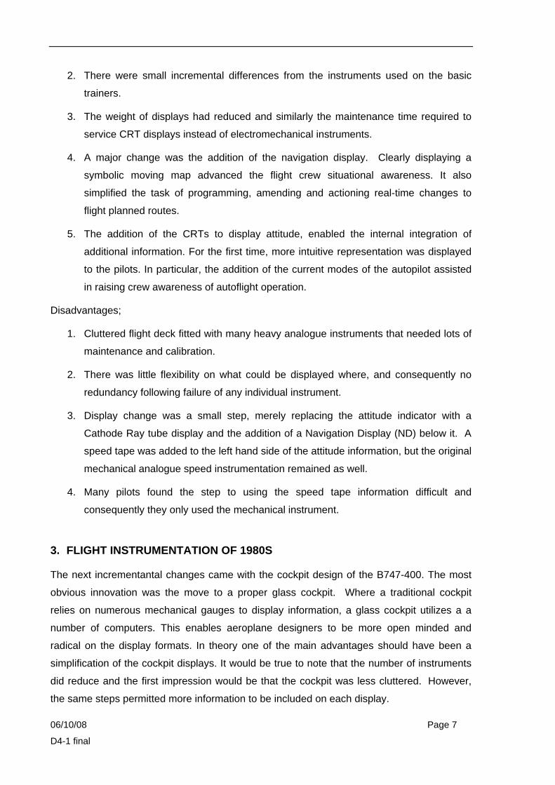
Figure 3. B777 Horizontal Situation Indicator
Figure 3 shows one method of displaying part of the lateral flight path. The main components
are as follows. The triangle represents the aeroplane, surrounded by a compass rose. The
point of the triangle shows the position, supported by GPS. The parallel white lines ahead of
the symbol is the programmed runway, in this case “27” to be used for the takeoff. The
planned route is shown as a magenta line. The symbol next to LON in the centre is used to
depict the LONDON ground based navigation aid and the digital display of distance of the
aeroplane to the aid is shown in both lower corners. In the air, the aeroplane track will be
shown as a solid white line. The layout of the display can be altered, changing the
orientation and position of the aeroplane symbol. On the same display ground navigation
information can also be displayed. The choice of format on this single instrument will be
dictated by the phase of flight and by individual pilot taste.
06/10/08 Page 12
D4-1 final
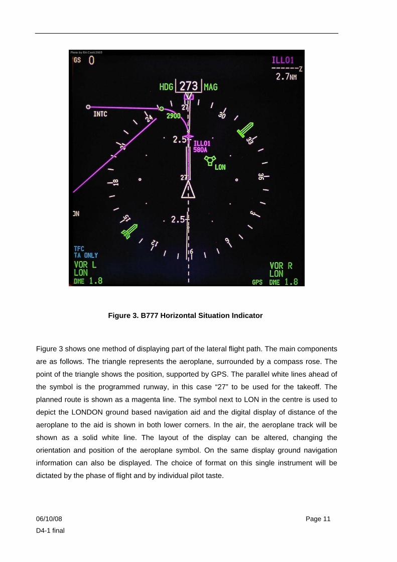
Figure 4. B777 Attitude Display Indicator
Figure 4 shows the aeroplane attitude as the centre reference. In manual pilot flight, this
instrument forms the centre of the instrument scan, in much the same way as the original
format formed of the centre part of the “T”. It is an electronic representation of the old
gyroscopic instrument. The aeroplane is centre; represented as a small white box, with
“wings” either side and a sky pointer shows the angle of bank against a non-graduated
display. Bank angles of 10,20,30, 45 and 60 degrees are displayed as white dashes. A
digital indicated airspeed tape is shown on the left; the current speed is boxed (30). The box
remains static relative to the instrument, and the tape moves down as the airspeed
increases. Barometric altitude is displayed on the right tape, with vertical speed to the
extreme right. Part of the horizontal situation indicator is shown at the bottom. The magenta
digits at the top left and right show a selected speed and altitude.
06/10/08 Page 13
D4-1 final
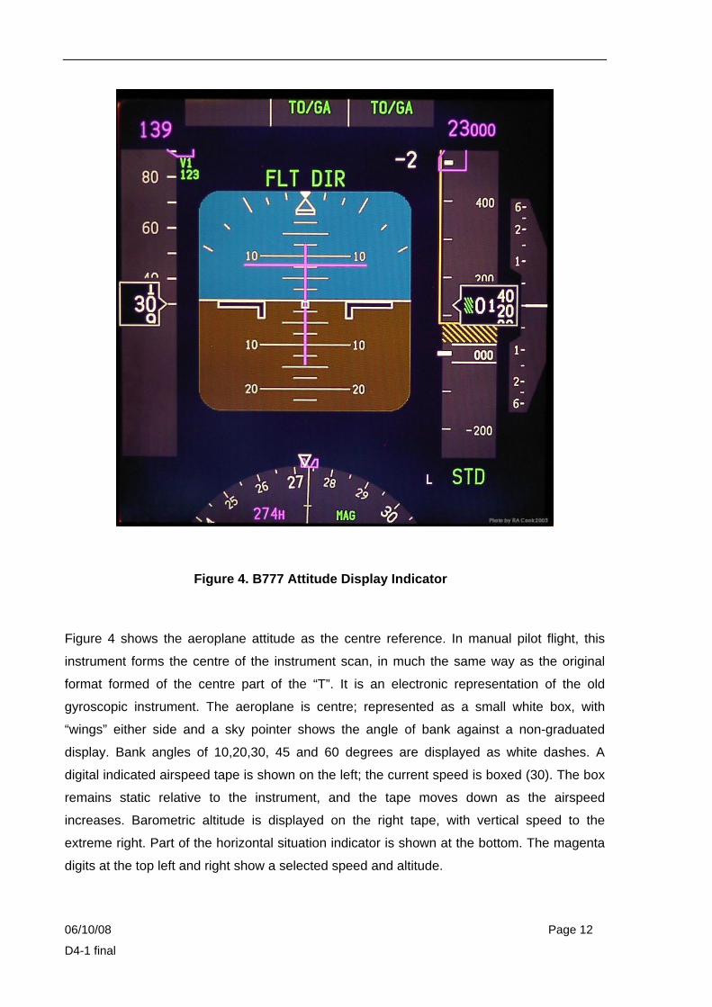
Figure 5. B 777 Flight Controls Synoptic Display
On one of the lower centre LCDs, a selection of system synoptic displays can be chosen, as
can an electronic checklist. Emergency checklists will also be displayed either automatically
or upon pilot manual selection. In figure 5, the position of the flight control surfaces can be
seen, showing the relative positions of ailerons, flaperons, rudder, elevator, spoilers and the
trim settings of the stabiliser and rudder. Other pages available to the crew will cover all the
major aeroplane systems, such as hydraulics, environmental control, and electrics.

06/10/08 Page 14
D4-1 final
Figure 6. B777 EICAS
On the B777, the Engine Information and Caution Advisory System (EICAS) display is
mounted centrally in the cockpit. The principle of the information displayed is to include what
the aeroplane manufacturers believe is the minimum required to operate the aeroplane at
the time. Consequently, in this case only N1 and EGT are displayed for the 2 engines. The
data to the top right refers to the warning and caution system and below that more text data
which are information to the pilot. Landing gear status and flap position (not shown because
the flaps are up) are below this and the fuel quantity in the bottom right. Additional engine
parameters may be selected by the pilot or will appear automatically in a failure scenario.
Advantages;
1. The electronic displays enable significantly more information to be portrayed. For
example the attitude indicator could be combined with the airspeed indicator and the
altimeter. This had the benefit of reducing the size of the pilot scan; only one
instrument was needed instead of the 3 previously used to gain the same information,
Moreover, the added flexibility of the electronic medium meant that variable

06/10/08 Page 15
D4-1 final
information derived from other systems could be displayed on an instrument. As a
result for example, the speed tape could show minimum and maximum operating
speeds generated by other systems (Flight Management and Stall computers).
2. The LCD displays were less susceptible to errors, more easily maintained and lighter.
Disadvantages
1. One of the advantages of the electronic format, additional display information, also
proved to be a disadvantage. Each "instrument" was now crammed with information,
but not necessarily in a way that was easily processed by the pilot. As a method of
monitoring the performance of the auto flight system, such limitations were not
significant. However, processing the information during manual flight is not so
straightforward and can have the effect of increasing pilot workload.
2. The introduction of new display formats was not always done to improve digestibility.
For example, the speed tape that was introduced to the Attitude Indicator was used
in the main because it took up less space than an analogue dial. It had long been
recognized that analogue information was more intuitive and provided clearer trend
information than tapes.
Figure 7. TCAS Display

06/10/08 Page 16
D4-1 final
All current commercial aeroplanes are installed with TCAS. It is designed primarily as display
to show pilots potential conflicting air traffic and where appropriate provide co-ordinated
vertical collision avoidance information, which the pilot should fly manually. This information
was initially shown on a separate instrument as in figure 7, but the current generation show
the same symbology integrated into the Navigation Displays. The display will now enable the
relative horizontal position to be shown and retain the difference in altitude and direction of
vertical travel. In the above display, there are 2 other aeroplanes ahead of the display
aeroplane; one in level flight 600 feet above and to the half right, the other just to the left of
the nose, 800 feet above and descending. Any resolution advisory is shown as a vertical
demand on the EADI, which must be flown by the pilot manually.
As stated the original idea of the display was to show relative position and threat/resolution
information. However, with pilot experience and practice, the same information can be used
to raise situational awareness and enable the pilot to “self radar vector” his own aeroplane.
For example, on approach the TCAS traffic ahead may be seen to be closer than the desired
3nm. This would encourage the pilot of the following aeroplane to slow down before being
instructed to by ATC. Similarly, the same displayed information can permit the pilot to cross-
check ATC clearances to prevent potentially catastrophic incorrect altitude changes before
reaches a point of resolution by the TCAS system.
5. NEXT GENERATION DISPLAYS
An example of the next generation of displays which are at the point of entering commercial
service can be seen on the A380. The A380 has taken many of the ideas from previous
types and attempted to improve the quality of information that is displayed. The main
purposes are to improve pilot situational awareness, increase the operational flexibility and
reduce overall crew workload. The B777 introduced a touch pad to move a cursor around
screens to help input and extract data from the flight management computers. The A380 has
taken this a step further, providing the pilots with a trackball and keypad, figure 8.

06/10/08 Page 17
D4-1 final
Figure 8. A380 Keyboard and Cursor Unit
The function of the unit is designed to be intuitive and enables the pilot great flexibility in
interfacing with the onboard computers. As a result the volume of information that is
available has increased significantly from previous generations. At this level of complexity,
different aeroplane manufacturers will have customised the layout and formats. The A380
represents the ideas of Airbus, but similar ideas are present, albeit in slightly different
concepts on the Boeing 787 and other manufacturers. This does present a controlling issue
for the regulators. If the flight test evaluation pilots believe that the design is fit for purpose,
even radical ideas can see their way into commercial aeroplanes. The A380 does have
some new ideas, some of which will be discussed next.
06/10/08 Page 18
D4-1 final
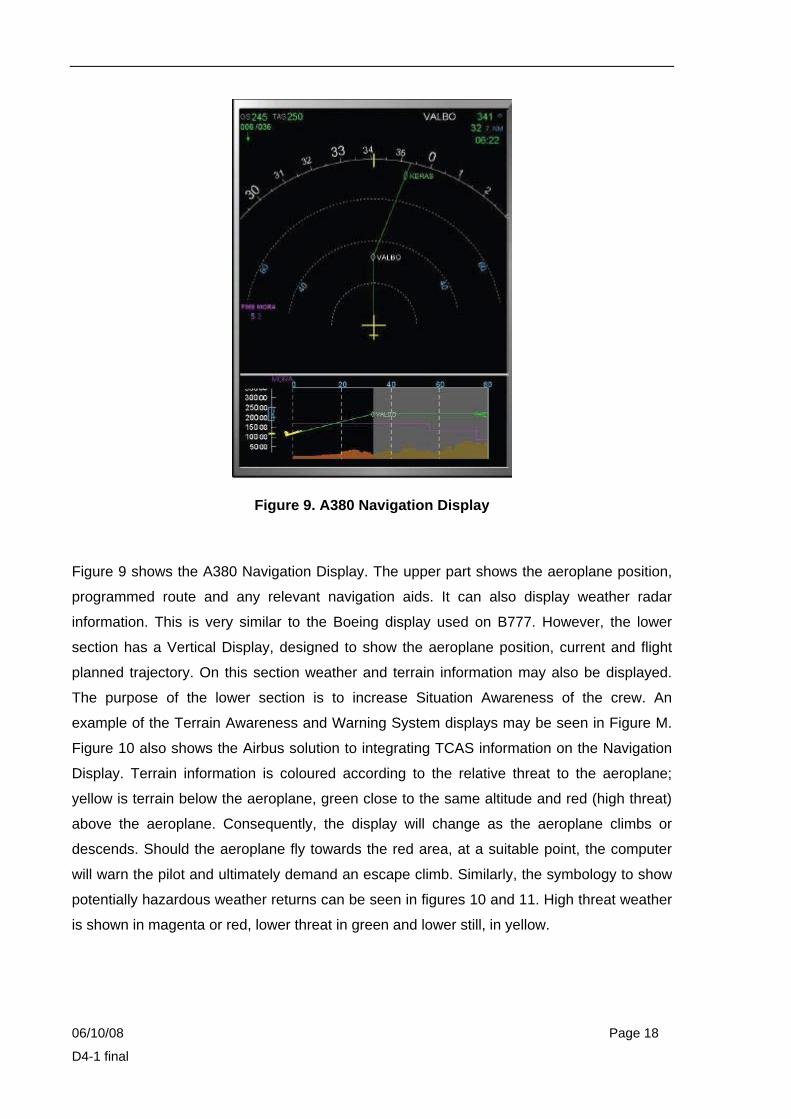
Figure 9. A380 Navigation Display
Figure 9 shows the A380 Navigation Display. The upper part shows the aeroplane position,
programmed route and any relevant navigation aids. It can also display weather radar
information. This is very similar to the Boeing display used on B777. However, the lower
section has a Vertical Display, designed to show the aeroplane position, current and flight
planned trajectory. On this section weather and terrain information may also be displayed.
The purpose of the lower section is to increase Situation Awareness of the crew. An
example of the Terrain Awareness and Warning System displays may be seen in Figure M.
Figure 10 also shows the Airbus solution to integrating TCAS information on the Navigation
Display. Terrain information is coloured according to the relative threat to the aeroplane;
yellow is terrain below the aeroplane, green close to the same altitude and red (high threat)
above the aeroplane. Consequently, the display will change as the aeroplane climbs or
descends. Should the aeroplane fly towards the red area, at a suitable point, the computer
will warn the pilot and ultimately demand an escape climb. Similarly, the symbology to show
potentially hazardous weather returns can be seen in figures 10 and 11. High threat weather
is shown in magenta or red, lower threat in green and lower still, in yellow.

06/10/08 Page 19
D4-1 final
Figure 10. A380 Terrain Awareness and Warning System
Figure 11. A380 Navigation Display

06/10/08 Page 20
D4-1 final
Figure 11 is designed to increase pilot awareness of potential weather threats in a 3D
context. In this case an area of turbulence is indicated as well as an area of predicted
windshear (PWS). This does represent a step forward in attempting to aid the pilot to assess
potential threats. However, it should be noted that there is a considerable amount of
information on display and the threat analysis is left to the experience and skill of the pilot. In
isolation the display looks straightforward, but it should be remembered that there are at
least 3 other large displays, each showing complex information that have to be processed
collectively by the crew.
It would seem appropriate at this point to highlight one of the fundamental philosophies in
aeroplane operation. Clearly there are many tasks in the normal operation of an aeroplane,
and significantly more so in a non-normal situation. How a pilot processes information,
threats and works with the other crew members has long been a subject for research. One
basic principle that is taught to commercial pilots of all experience and ability is Aviate-
Navigate-Communicate (ANC). In any scenario, normal or non-normal, the crew needs to
ensure that someone is nominated to ensure the safe flight-path of the aeroplane. This may
be the autopilot, but even in this case one pilot at least will be tasked with monitoring the
autoflight performance. This done, the next priority will be to navigate and finally to tell the
relevant people what is happening. To this end the instrumentation must be compatible and
enable the crews to complete these sub-tasks with the minimum workload. To aviate the
pilot needs to be able to process the information that is displayed, hopefully in an
unambiguous way. The same may be said of navigate and communicate. The airline
manufacturers would argue that the current suite of instruments satisfy all the requirements
and the analysis of accidents/incidents (or lack of!) would indicate that this is largely true.
This does not mean that the displays are "ideal". It does mean that at present, no one has
presented a strong enough case to make a radical change. The operation of a commercial
aeroplane involves considerably more than just A-N-C. It is recognised that there is a need
to add M (for manage). Thus the original concept was extended in recognition of the fact that
it was the overall operation and management of the flight that created most of the problems
and safety concerns. Analysis of most of the incidents, accidents and trends of potential
incidents, indicated that a large percentage did not occur from a single poor handling
occurrence, but from a series of incidents that at various stages prior could have been
mitigated against. The ability to plan, and brief a plan at an appropriate time significantly
enhanced the situational awareness of the crew and reduced the likelihood of immediate
recovery responses. Furthermore, it was realised that this extended beyond the flight itself,
back to the pre-brief. As a result there has been significant investment in systems that can

06/10/08 Page 21
D4-1 final
be used at an early stage of a trip, and integrated into the aeroplane. The A380 uses some
of this technology, as does the B787.
For example, the A380 has the capability to display to the pilot a wide variety of previously
unused data. Figure 12 is one such display. On the ground, Airport Navigation information
may be displayed on the Navigation Display. This is designed to increase position
awareness while taxiing around airports and may be seen as a key contributor to help
prevent inadvertent runway incursions.
Figure 12. A380 Navigation Display
Figure 13. A380 Airport Map
06/10/08 Page 22
D4-1 final
Figure 13 shows one of the many displays that may be available to pilots through systems
that have been collectively called the Electronic Flight Bag (EFB). In this case the onboard
information system on the A380 enables the pilot to reference a wealth of information, in this
example, complex airport charts. There are many solutions to the concept of the EFB. One
development is a portable laptop computer that can be loaded with the relevant flight
information and docked at the pilot position. Another solution are onboard computers that
are part of the aeroplane, but may be accessed through either datalink or flash memory
cards. What is important is that the next generation of aeroplanes will have unlimited
information available; all of which has to be controlled carefully. The additional complexity
associated with potential information overload may prove to be difficult problem to solve and
regulate.
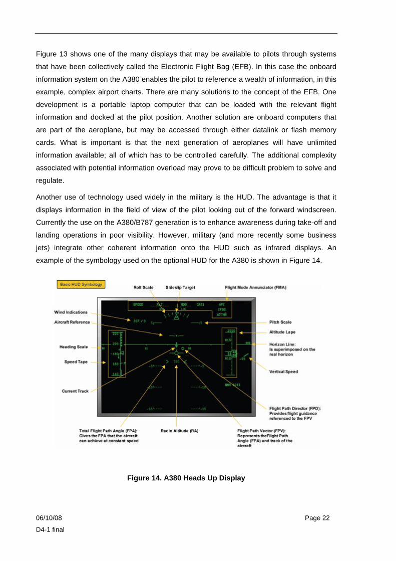
Another use of technology used widely in the military is the HUD. The advantage is that it
displays information in the field of view of the pilot looking out of the forward windscreen.
Currently the use on the A380/B787 generation is to enhance awareness during take-off and
landing operations in poor visibility. However, military (and more recently some business
jets) integrate other coherent information onto the HUD such as infrared displays. An
example of the symbology used on the optional HUD for the A380 is shown in Figure 14.
Figure 14. A380 Heads Up Display
06/10/08 Page 23
D4-1 final
It will be noted that much of the layout is similar to the EADI, with the addition of a flight path
director and flight path vector.
Another new concept on the A380 demonstrates vividly the concept of A-N-C-M. During the
cruise portion of the flight, at a time of low workload, the pilot can call up a map of the
destination airfield. He can select his intended landing runway and using planning data
within the aeroplane computer select a point on the runway that he would like to vacate,
within the performance limitations expected at the time of arrival. The computer will select
the appropriate wheel brake setting to achieve this. This is at the planning stage. During the
latter stages of the approach a similar display will show the dynamic performance against
this planning criteria. The same display used for planning will show the dynamic
performance on the map of the runway. This is designed to show, visually, the performance
against the selected vacate point. Thus if the plane is flying too fast to enable the braking
performance to achieve the vacate point, the pilot will be informed and the display will clearly
indicate the situation. Should the dynamic performance be such that the aeroplane will not
stop on the selected runway at all, the pilot will be advised to discontinue the approach and
go-around.
Advantages;
1. Display technology builds on the previous types.
2. Significantly more information available with the introduction of methods to enhance 3d
awareness of position and potential threats.
3. Use of high technology solutions to enhance pre-flight briefing and reduce the time to
prepare the aeroplane for flight by uploading data into the aeroplane computers.
4. Use of onboard management computers to monitor stopping performance, indicate the
performance dynamically during the critical stages of approach and act as an effective
"dead-mans brake" if stopping performance is exceeded.
Disadvantages;
1. A lot of information to process.
2. Control or regulation on the use of management tools in particular becomes
significantly more difficult.
06/10/08 Page 24
D4-1 final
6. FUTURE DISPLAY SOLUTIONS:
Potential areas that could be considered for improvements to cockpit displays are as follows:
a. TCAS Potential TCAS alerts could be projected to the pilots, to allow them to modify rates
of climbs/descents earlier. Similar in concept to the ATC collision alert systems. This would
work at a lower threshold level than the traditional TA. It should also be possible for future
TCAS to provide an earlier lateral resolution. The resolution advisory would be shown on the
EADI. However, in recognition of the fact that more flight will be done automatically, this
should be an area where the handling pilot "accepts" the RA allowing the autopilot to
execute the RA; the display would therefore be a monitor of autopilot performance.
b. CPDLC. Currently ATC clearances are received as a datalink text message. It would be
better if the flight management computer automatically up loaded the proposed air traffic
route/amendment onto the planning section of the ND to allow the pilots to consider the
route. If accepted, a message would automatically be sent to ATC to accept the
amendment.
c. EMERGENCY DRILLS. Currently drills and checklists are displayed to the pilot following
a non-normal event. Current designs typically use the same display screen that is used for
the synoptic/system pages. It would be better if the relevant system page was displayed in
addition to the drill/checklist. The operation of the correct procedure could then be clearly
observed on the synoptic page.
d. INFORMATION. Currently there is a lot of information that is displayed to the pilot
continuously, that is not required. A good example would be the engine displays, they clutter
up a lot of the available display space with very little of the information being any use during
normal operation. The requirement to display temperatures and oil pressures etc. is not
required for the day-to-day operation of the aircraft. Modern engine control computers take
care of fuel metering and monitoring and most information is of no use to the pilot. Any
cautions, could be brought to the pilot’s knowledge using the normal alerting system with the
appropriate system synoptic being displayed. A simple, single analogue/ or strip display of
the current power selected would be sufficient for operation of the aircraft; this could be
graduated 1 to 10 or 1 to 100. Only one would be required, in normal operation, regardless
of the number of engines.
06/10/08 Page 25
D4-1 final
Other information is displayed all the time that is not required; examples include positions of
undercarriage and flaps/slats. Normally they are retracted in flight and therefore do not need
to be displayed. Their position could just be indicated on the ground and in flight until they
had been retracted successfully. Similarly the position of the services could be shown to the
pilot on first selection of the respective item.
e. ENERGY MANAGEMENT. In general, the area where energy management is of the
most concern to the pilot is the approach phase. To manage the flight efficiently, current
pilot’s aim to fly constant descent approaches (CDA’s), this allows the descent to the final
approach speed and altitude to be progressive and, ideally, at idle power. Due to the large
number of variables involved, e.g. wind, aircraft weight, aircraft speed and configuration, it is
very difficult for a pilot to achieve the final approach position with the right amount of energy.
The current systems allow vertical descent performance to be shown relative to the
speed/altitude gates entered into the FMC. However, the number of rushed or high-energy
approaches that occur on the line, prove that what is currently on offer to be inadequate.
Similarly, many more approaches are flown on the side of caution and below the ‘idle CDA’
profile. This is less fuel efficient.
In the future, it would be highly desirable to have an intuitive display to show whether or not
the current energy level is too high or too low would enable pilots to maintain the correct
profile all the way to the final approach. It could be used to delay final configuration until the
last possible moment, allowing a much more efficient/economical approach. This is an
extension of the concept used on the A380 for managing the landing roll.
f. DYNAMIC TAKE-OFF INFORMATION. Currently pilots calculate their take-off
performance prior to departure, using winds/temperatures and surface conditions that are
taken from an ATIS that could be out of date. In the future the decision speed (V1) could be
updated automatically during the take off roll, depending on acceleration rate and distance to
go to the end of the runway. The rotate and V2 speeds will remain constant, as they are a
function of the aircraft weight and power selected for take off.
Pilots try to use the minimum power required for take off as this preserves engine life.
However they are often not sure of what departure point on the runway they will be allocated
by air traffic control and consequently, conservatively, plan to take off at an intersection point
that gives significantly less take-off runway than they actually use. This is particularly the
case at very busy airfields, such as London Heathrow. In the future as the aircraft knows,
from its position, how much runway remains, it could set the minimum required power from

06/10/08 Page 26
D4-1 final
that specific point rather than that initially planned. This would have a dual benefits; it would
prevent pilots taking off with too little power (worse case) and it would mean that the
minimum safe amount of power would always be applied with the associated cost benefits.
g. TIME DISPLAYS. One of the future developments in aviation, must be to make better use
of planning tools and allow civil airliners to work more efficiently. By reducing the amount of
time that an aircraft stays in the air, reduces both the economic and ecological cost.
Currently with the planning tools available a pilot knows very accurately how long the flight
will take. What he does not know, and consequently is forced to carry more fuel, to cover
the contingency, is whether or not there will a significant delay to his arrival at destination
due to congestion. In an ideal world the departure airport taxy time would be known, as
would the projected flight time, including a planned arrival and landing runway at the
destination. The aeroplane should then be able to "bid" for a landing slot at the destination.
The destination airfield would process all the bids and allocate a time. Based on this the
aeroplane would start to satisfy that "bid". As the flight becomes dynamic and realtime
events such as increases in wind take effect, the bidding process would continue for all
arrivals. The aeroplane computers would "manage" this changeing bid by slowing or
speeding up within suitable performance limits. This would have the effect of reducing fuel
inefficient holds.
h. RUNWAY UTILISATION. With increasing density of air traffic, it becomes more important
to use runways as efficiently as possible.
On arrival, to maximise runway utilisation, air traffic agencies try to separate aircraft by a
minimum allowed distance. This works reasonably well in calm conditions, but whenever the
wind speed increases, this reduces the arrival rate into the airfield. This is simply because
aircraft normally land into wind, so with a stronger wind their ground speed is reduced. With
a reduced groundspeed, it obviously takes longer for the aircraft to cover the assigned
separation distance. Future displays and automation could allow for the current wind speeds
and automatically apply the minimum required separation from the preceding aircraft.
On departure, there are internationally agreed separation times between departing aircraft.
The laid down minima are designed to keep the following aircraft clear of any wake vortex
from the proceeding aircraft. Currently these times are designed to cover the worst case
scenario, normally that when there is a gentle 5 knot crosswind, keeping one of the
spreading wing tip vortices near to the departure runway. Most departures are not subjected
to these conditions and could, therefore, depart much closer to the aircraft in front. Future
06/10/08 Page 27
D4-1 final
instrumentation could add the departing aeroplane to the navigation display (ND) and also
display the wing tip vortices and their likely position and strength, depending on the current
wind speed and preceding aircraft type. This would normally enable an aircraft to depart at a
closer distance to the aircraft in front and therefore significantly increase the runway
utilisation.
i. ALTITUDE or FLIGHT LEVEL SELECTION. Currently all cockpits have a selector for
altitude. The same instrument is used to select the flight level, even though what is displayed
is not a flight level. For example, if ATC clear the aeroplane to FL310, the pilot will select
31000 in the Mode Control Panel. This is the same as 31000 feet, although the two are not
the same. It is surprising that this has never been addressed since altitude excursions have
long been recognised as a significant flight safety threat.
7. CONCLUSIONS
The development in display formats tends to have come in steps; often as one of the major
aeroplane manufacturers releases a new aeroplane type. Historically, the changes have
been incremental, building on the previous design formats. Each step tends to result in a
noticeable increase in the information displayed to the flight crew. Not all the changes have
improved the ability of the display to show the pilots clear, unambiguous information. Current
and arriving technologies have built on the overal mission/flight, starting at the pre-brief
stage with off-board computers integrated to on-board flight management computers. Future
designs will only be accepted by conservative commercial pilots if they are incremental. The
majority of future flights will be automated PRNAV departures/arrivals and great circle,
optimum flight level 3D navigation routes. These can only be optimised for fuel efficiency if
integrated with 4D ATC solutions. As a result of this most future technologies will be directed
towards the "management" displays. These will still need to be clear and unambiguous. On-
board computers will monitor dynamic performance.
There is legitimate debate on how high tech future displays could become; should they be
projected or 3D? For example, the HUD could have a "tunnel of flight" displayed, with most
of the digits removed. The consideration should be; would this improve safety or
performance over the current display? Overall, it should be remembered that there is a
progressive move to more automated flight with the pilot managing the processes. In this
light the correct process is to identify the task, determine the pilot need, and finally provide
the display that satisfies that need. Therefore, the areas that will most benefit display
06/10/08 Page 28
D4-1 final
solutions are likely to be the flight briefing/management tools. It it more likely that there will
continue to be only small incremental changes to flight instruments.
8. REFERENCES
1. Airbus - A380 Flight Deck and Systems Briefing for Pilots 2. R.Cook – B777 Flight Deck display photographs