Cardiovascular magnetic resonance artefacts - Cardiovascular...Cardiovascular Magnetic Resonance...
39
REVIEW Open Access Cardiovascular magnetic resonance artefacts Pedro F Ferreira 1,2* , Peter D Gatehouse 1,2 , Raad H Mohiaddin 1,2 and David N Firmin 1,2 Abstract The multitude of applications offered by CMR make it an increasing popular modality to study the heart and the surrounding vessels. Nevertheless the anatomical complexity of the chest, together with cardiac and respiratory motion, and the fast flowing blood, present many challenges which can possibly translate into imaging artefacts. The literature is wide in terms of papers describing specific MR artefacts in great technical detail. In this review we attempt to summarise, in a language accessible to a clinical readership, some of the most common artefacts found in CMR applications. It begins with an introduction of the most common pulse sequences, and imaging techniques, followed by a brief section on typical cardiovascular applications. This leads to the main section on common CMR artefacts with examples, a short description of the mechanisms behind them, and possible solutions. Review Introduction There are unique motion and other issues involved in Car- diovascular Magnetic Resonance (CMR) that can lead to artefacts which can obscure or easily be misinterpreted as pathology. An artefact can be defined as something that is visible in an image but it is artificial, and is often detri- mental to diagnosis. For this reason it is important to have an understanding of the physical principles behind the for- mation of such artefacts so that they can be identified and possibly avoided. A large range of different sequences are used for the different applications in CMR and the majority of these are still being developed to improve their accuracy and reliability. It is therefore impossible to be completely comprehensive covering all artefacts for all sequences, thus the examples of artefact have been restricted to one or two of the most problematic or common. The arte- facts are also specific to cardiovascular imaging, and more general artefacts related to hardware are omitted. This article, that is designed for a clinical readership, follows previous publications on the subject [1-3]. There is initially a brief description of the most common se- quences and preparation pulses used, along with imaging techniques and typical cardiovascular applications. The main section follows, with common examples of arte- facts, accompanied with a small description of the mech- anisms behind them and possible solutions and trade- offs. At this point it is quite possible that some readers will not require the introductory sections describing car- diovascular pulse sequences and applications and would happily move directly to the main sections describing ar- tefacts. If this is the case then please jump to section Cardiovascular Magnetic Resonance Artefacts. Also, al- ternatives to these sections are available elsewhere such as the excellent physics articles from Ridgway and Biglands in JCMR 2010 and 2012 [4,5]. Cardiovascular pulse sequences Both spin-echo and gradient-echo pulse sequences play a major role in CMR. Spin-echo sequences refocus the excited signal with a 180° pulse or pulses (Figure 1a) which makes them robust to off-resonance effects and able to use longer TE (Time of Echo) values than gradient-echo sequences (Figure 1b). Off-resonance re- fers to a small deviation in the local spins' resonant fre- quency in relation to the nominated scanner centre frequency. This can be caused, for example, by main field inhomogeneities or magnetic susceptibilities. Spin-echo Generally spin-echo sequences offer a greater flexibility in obtaining different contrasts (T1-weighted, T2-weighted, or proton-density weighted) depending on the choice of TE and TR (Time of Repetition). The main disadvantages of spin-echo sequences are their limited temporal-resolution and sensitivity to motion and flow. Spin-echo acquisition times can be shortened by use of a multi-echo approach where multiple refocused echoes * Correspondence: [email protected] 1 National Heart and Lung Institute, Imperial College, London, UK 2 Royal Brompton Hospital, London, UK © 2013 Ferreira et al.; licensee BioMed Central Ltd. This is an Open Access article distributed under the terms of the Creative Commons Attribution License (http://creativecommons.org/licenses/by/2.0), which permits unrestricted use, distribution, and reproduction in any medium, provided the original work is properly cited. Ferreira et al. Journal of Cardiovascular Magnetic Resonance 2013, 15:41 http://jcmr-online.com/content/15/1/41
-
Upload
truongkien -
Category
Documents
-
view
221 -
download
2
Transcript of Cardiovascular magnetic resonance artefacts - Cardiovascular...Cardiovascular Magnetic Resonance...

Ferreira et al. Journal of Cardiovascular Magnetic Resonance 2013, 15:41http://jcmr-online.com/content/15/1/41
REVIEW Open Access
Cardiovascular magnetic resonance artefactsPedro F Ferreira1,2*, Peter D Gatehouse1,2, Raad H Mohiaddin1,2 and David N Firmin1,2
Abstract
The multitude of applications offered by CMR make it an increasing popular modality to study the heart and thesurrounding vessels. Nevertheless the anatomical complexity of the chest, together with cardiac and respiratorymotion, and the fast flowing blood, present many challenges which can possibly translate into imaging artefacts.The literature is wide in terms of papers describing specific MR artefacts in great technical detail. In this review weattempt to summarise, in a language accessible to a clinical readership, some of the most common artefacts foundin CMR applications. It begins with an introduction of the most common pulse sequences, and imaging techniques,followed by a brief section on typical cardiovascular applications. This leads to the main section on common CMRartefacts with examples, a short description of the mechanisms behind them, and possible solutions.
ReviewIntroductionThere are unique motion and other issues involved in Car-diovascular Magnetic Resonance (CMR) that can lead toartefacts which can obscure or easily be misinterpreted aspathology. An artefact can be defined as something that isvisible in an image but it is artificial, and is often detri-mental to diagnosis. For this reason it is important to havean understanding of the physical principles behind the for-mation of such artefacts so that they can be identified andpossibly avoided.A large range of different sequences are used for the
different applications in CMR and the majority of theseare still being developed to improve their accuracy andreliability. It is therefore impossible to be completelycomprehensive covering all artefacts for all sequences,thus the examples of artefact have been restricted to oneor two of the most problematic or common. The arte-facts are also specific to cardiovascular imaging, andmore general artefacts related to hardware are omitted.This article, that is designed for a clinical readership,
follows previous publications on the subject [1-3]. Thereis initially a brief description of the most common se-quences and preparation pulses used, along with imagingtechniques and typical cardiovascular applications. Themain section follows, with common examples of arte-facts, accompanied with a small description of the mech-anisms behind them and possible solutions and trade-
* Correspondence: [email protected] Heart and Lung Institute, Imperial College, London, UK2Royal Brompton Hospital, London, UK
© 2013 Ferreira et al.; licensee BioMed CentralCommons Attribution License (http://creativecreproduction in any medium, provided the or
offs. At this point it is quite possible that some readerswill not require the introductory sections describing car-diovascular pulse sequences and applications and wouldhappily move directly to the main sections describing ar-tefacts. If this is the case then please jump to sectionCardiovascular Magnetic Resonance Artefacts. Also, al-ternatives to these sections are available elsewhere suchas the excellent physics articles from Ridgway andBiglands in JCMR 2010 and 2012 [4,5].
Cardiovascular pulse sequencesBoth spin-echo and gradient-echo pulse sequences playa major role in CMR. Spin-echo sequences refocus theexcited signal with a 180° pulse or pulses (Figure 1a)which makes them robust to off-resonance effects andable to use longer TE (Time of Echo) values thangradient-echo sequences (Figure 1b). Off-resonance re-fers to a small deviation in the local spins' resonant fre-quency in relation to the nominated scanner centrefrequency. This can be caused, for example, by mainfield inhomogeneities or magnetic susceptibilities.
Spin-echoGenerally spin-echo sequences offer a greater flexibility inobtaining different contrasts (T1-weighted, T2-weighted, orproton-density weighted) depending on the choice of TEand TR (Time of Repetition). The main disadvantages ofspin-echo sequences are their limited temporal-resolutionand sensitivity to motion and flow.Spin-echo acquisition times can be shortened by use of
a multi-echo approach where multiple refocused echoes
Ltd. This is an Open Access article distributed under the terms of the Creativeommons.org/licenses/by/2.0), which permits unrestricted use, distribution, andiginal work is properly cited.
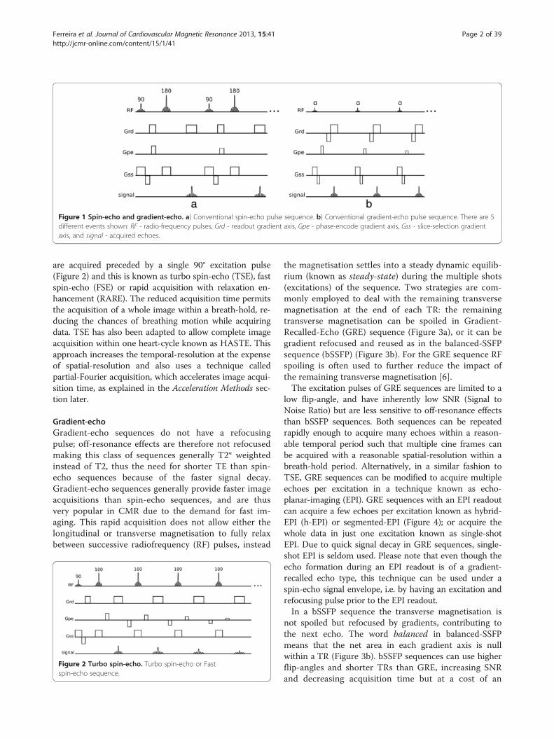
Figure 1 Spin-echo and gradient-echo. a) Conventional spin-echo pulse sequence. b) Conventional gradient-echo pulse sequence. There are 5different events shown: RF - radio-frequency pulses, Grd - readout gradient axis, Gpe - phase-encode gradient axis, Gss - slice-selection gradientaxis, and signal - acquired echoes.
Ferreira et al. Journal of Cardiovascular Magnetic Resonance 2013, 15:41 Page 2 of 39http://jcmr-online.com/content/15/1/41
are acquired preceded by a single 90° excitation pulse(Figure 2) and this is known as turbo spin-echo (TSE), fastspin-echo (FSE) or rapid acquisition with relaxation en-hancement (RARE). The reduced acquisition time permitsthe acquisition of a whole image within a breath-hold, re-ducing the chances of breathing motion while acquiringdata. TSE has also been adapted to allow complete imageacquisition within one heart-cycle known as HASTE. Thisapproach increases the temporal-resolution at the expenseof spatial-resolution and also uses a technique calledpartial-Fourier acquisition, which accelerates image acqui-sition time, as explained in the Acceleration Methods sec-tion later.
Gradient-echoGradient-echo sequences do not have a refocusingpulse; off-resonance effects are therefore not refocusedmaking this class of sequences generally T2* weightedinstead of T2, thus the need for shorter TE than spin-echo sequences because of the faster signal decay.Gradient-echo sequences generally provide faster imageacquisitions than spin-echo sequences, and are thusvery popular in CMR due to the demand for fast im-aging. This rapid acquisition does not allow either thelongitudinal or transverse magnetisation to fully relaxbetween successive radiofrequency (RF) pulses, instead
Figure 2 Turbo spin-echo. Turbo spin-echo or Fastspin-echo sequence.
the magnetisation settles into a steady dynamic equilib-rium (known as steady-state) during the multiple shots(excitations) of the sequence. Two strategies are com-monly employed to deal with the remaining transversemagnetisation at the end of each TR: the remainingtransverse magnetisation can be spoiled in Gradient-Recalled-Echo (GRE) sequence (Figure 3a), or it can begradient refocused and reused as in the balanced-SSFPsequence (bSSFP) (Figure 3b). For the GRE sequence RFspoiling is often used to further reduce the impact ofthe remaining transverse magnetisation [6].The excitation pulses of GRE sequences are limited to a
low flip-angle, and have inherently low SNR (Signal toNoise Ratio) but are less sensitive to off-resonance effectsthan bSSFP sequences. Both sequences can be repeatedrapidly enough to acquire many echoes within a reason-able temporal period such that multiple cine frames canbe acquired with a reasonable spatial-resolution within abreath-hold period. Alternatively, in a similar fashion toTSE, GRE sequences can be modified to acquire multipleechoes per excitation in a technique known as echo-planar-imaging (EPI). GRE sequences with an EPI readoutcan acquire a few echoes per excitation known as hybrid-EPI (h-EPI) or segmented-EPI (Figure 4); or acquire thewhole data in just one excitation known as single-shotEPI. Due to quick signal decay in GRE sequences, single-shot EPI is seldom used. Please note that even though theecho formation during an EPI readout is of a gradient-recalled echo type, this technique can be used under aspin-echo signal envelope, i.e. by having an excitation andrefocusing pulse prior to the EPI readout.In a bSSFP sequence the transverse magnetisation is
not spoiled but refocused by gradients, contributing tothe next echo. The word balanced in balanced-SSFPmeans that the net area in each gradient axis is nullwithin a TR (Figure 3b). bSSFP sequences can use higherflip-angles and shorter TRs than GRE, increasing SNRand decreasing acquisition time but at a cost of an

Figure 3 GRE and bSSFP. a) Spoiled gradient-recalled echo sequence. b) Balanced steady-state free precession sequence.
Ferreira et al. Journal of Cardiovascular Magnetic Resonance 2013, 15:41 Page 3 of 39http://jcmr-online.com/content/15/1/41
increase in sensitivity to field inhomogeneity andfrequency-offsets.
Preparation pulsesMany different cardiovascular imaging sequences arecombined with preparation pulses. These pre-pulses pre-cede the host-sequence and can be used to suppress spe-cific tissues such as blood or fat, enhance contrastweighting and add tags to the myocardium for example.Some of the most common preparation pulses are nowdescribed.
Inversion pulsesInversion pulses invert the longitudinal magnetisationfrom its resting (“equilibrium” or full-recovery) valueusually labelled Mz =M0 to Mz = −M0 leading to signedlongitudinal magnetisation recovery that is initiallynegative and then positive on its return to equilibriumM0 (Figure 5a). This type of pulse is often used to se-lectively null signal from tissues with a particular T1.Inversion pulses can be non-selective, inverting all lon-gitudinal magnetisation over a large volume; spatially-selective by applying an amplitude modulation and agradient; or spectrally selective (this type of inversionpulses can be used for example to invert or null the sig-nal of fat only).
Saturation pulsesSimilar to inversion pulses, saturation pulses can also beused to modify contrast in an image (Figure 5b). Insteadof inverting the magnetisation, a saturation pulse rotates
Figure 4 Hybrid EPI. Hybrid-EPI with 4 echoes per-shot.
the magnetisation into the transverse x-y plane where it isspoiled by a gradient, resulting in zero net magnetisation.Following both inversion and saturation pulses, the
longitudinal magnetisation starts to recover towardsequilibrium, and image acquisition with one of the hostsequences occurs during this recovery. These techniquesare therefore called inversion-recovery or saturation-recovery preparation pulses. Different tissues have differ-ent T1 values and therefore different available signalduring recovery; these recovery techniques allow imagecontrast between different tissues to be manipulated. Itshould be noted however that the final contrast is notjust dependent on the preparation pulses but also on thehost sequence.Optimal saturation recovery preparation is generally
achieved by the use of special RF pulse designs (compos-ite [7], B1 Independent Rotation (BIR) [8]). Contrast ma-nipulation is somewhat more limited than with inversionrecovery pulses, although there are shorter recoverytimes from saturation. A major advantage of saturationrecovery is that it does not require near full longitudinalrecovery before the next saturation is applied, unlike in-version recovery, because the magnetisation is always re-set to zero by the saturation pulse; therefore offeringinsensitivity to arrhythmias. These pulses are commonlyused in first-pass perfusion imaging to enhance the con-trast agent signal.Saturation pulses can be also used to suppress un-
wanted tissues. This suppression can be either spatially-selective or spectrally-selective or both, reducing thesignal from defined spatial regions in the body, or fromdefined nuclei with specific chemical shifts respectively.Saturation bands can be used for example to suppressaliasing of tissue outside the field of view or signalghosting from flowing blood, while spectrally-selectivesaturation pulses are commonly used to null the signalof fat, commonly known as fat-saturation pulses. Thesetypes of saturation pulses differ from a saturation recov-ery preparation in the sense that the main objective is tonull signal instead of manipulating contrast with spin-relaxation; thus this type of preparation is commonlyfollowed by a spoiler-gradient in order to destroy any

Figure 5 Preparation pulses. a) Inversion recovery pulse. b) Saturation recovery pulse. Both figures a and b show the longitudinalmagnetisation recovery after the preparation pulse for two different T1 values (T1 red < T1 blue). Please note that in both a and b diagrams theeffects on the longitudinal magnetisation by the host sequence are not considered. c) SPAMM tagging preparation showing the spatialmodulation of the available longitudinal magnetisation following two 45 degree pulses prior to the host sequence.
Ferreira et al. Journal of Cardiovascular Magnetic Resonance 2013, 15:41 Page 4 of 39http://jcmr-online.com/content/15/1/41
transverse magnetisation, and followed immediately bythe excitation pulse in the host sequence, with no recov-ery time.
Tagging pulsesAnother form of preparation pulse used in CMR is thetagging pulse. This pulse introduces spatial tags, i.e.spatially periodic signal intensity modulation in theimage and is commonly used to evaluate tissue deform-ation, such as myocardial strain throughout the cardiaccycle. Tagging pulses are commonly applied immediatelyafter each R-wave followed by a segmented-image acqui-sition of multiple frames during the heart-cycle, toenable reconstruction of a cine. In a popular taggingpreparation technique known as SPAMM [9], non-selective pulses are interleaved with a tagging gradientand followed by a spoiler gradient (Figure 5c). This prep-aration introduces a sinusoidal modulation in Mz alongthe tag gradient direction, represented by Gx in theFigure. This technique is usually applied separately inboth in-plane spatial encoding directions and then com-bined in order to create a perpendicular grid. The con-trast of the tag lines can be improved by summing twosets of images with complementary tagging pulses, in atechnique called CSPAMM [10].
k-space samplingThe data collected by the scanner needs to be convertedto the final image. The acquired raw-data domain iscommonly known as k-space and is mathematically re-lated to the final image by a Fourier transformation.Thus each data value in k-space contains informationabout potentially any pixel in the final image, although abasic relationship can be considered between k-spaceand the image-space. The central region of k-space
contains information about low spatial frequencies, i.e.mainly the contrast in the image, while the outer regionsof k-space contain information about the high spatialfrequencies, i.e. object-boundaries and edges [4]. This re-lationship between k-space and image-space allows themanipulation of artefacts and image contrast by modify-ing the way k-space is sampled. Many different k-spacesampling trajectories have been proposed and used forcardiac imaging. In this section a brief introduction ismade to some of these techniques, while associated arte-facts are presented later on. Most of these techniquesare simply a method of sampling k-space and thereforecan be used with different sequences and techniques.The most common k-space sampling trajectories are
Cartesian, i.e. each data point is located in a Cartesiangrid, with each echo filling an entire phase-encoded line.This is by far the most simple and robust method, butnot necessarily the most efficient. Cartesian k-spacesampling can still be divided into different orders ofacquiring the phase-encoded lines known as phase-order(also called view-order, or k-space order), differentphase-orders present advantages and drawbacks in termsof artefacts as discussed later. The most common phase-orders are: sequential order; centric order; and reversecentric order (Figure 6a-c). For so called segmented ac-quisitions the sequential lines are either acquired moresparely and interleaving is used to fill the spare regions(Figure 6d); or simply fill k-space in sequential blocksover the raw-data.Still in the realm of Cartesian trajectories we have EPI
readouts, where more than one line is acquired in agradient-echo train (Figure 6e). EPI uses bipolar readoutgradients (Figure 4), which continuously produce echoes,making it a fast k-space sampling method. In its mostcommon form EPI, although being Cartesian requires

Figure 6 K-space sampling phase order. a) Sequential order. b) Centric order. c) Reverse centric order. d) Linear interleaved order. e) EPItrajectory (please note, no sampling is made during phase-encode (vertical) displacements).
Ferreira et al. Journal of Cardiovascular Magnetic Resonance 2013, 15:41 Page 5 of 39http://jcmr-online.com/content/15/1/41
extra image processing steps due to half the echoes (oddechoes) being acquired in k-space with the opposite dir-ection to even echoes. Although highly efficient, EPI isalso very sensitive to many different artefacts, especiallyin its single-shot form and for this reason hybrid-epi ispopular where shorter EPI trains are commonly acquiredwith only a few echoes or lines, instead of the whole ofk-space.k-space sampling can also have non-cartesian trajec-
tories, with the most common being spiral or radial. Ina spiral acquisition each k-space line follows a spiral tra-jectory (Figure 7a), this is efficient in the sense that itachieves a greater coverage of k-space with fewer shotsthan Cartesian. Also a spiral acquisition collects a circu-lar area of k-space and therefore ignores the corners ofk-space which are collected with a Cartesian acquisitionbut don’t necessarily contribute to the final image. Simi-larly to EPI, spiral acquisitions can sample the entire k-
Figure 7 Non-Cartesian sampling: Spiral and Radial. a) Spiral k-space trzoomed in on the left. Below is shown a sequence diagram of the acquisitsequence diagram for the acquisition of two radial lines.
space either with one shot or with multiple spiral inter-leaves. The single shot approach is again more efficientbut prone to artefacts. Spirals do not have a phase andfrequency-encode gradient, instead there is a 2D readoutgradient waveform that is sinusoidal with frequency andwith varying amplitudes. The rate of increasing radius ofeach spiral line and also the rate of sampling in a lineare defined by the Nyquist sampling requirements,which state that in order to reconstruct a signal from asequence of samples, the frequency of samples must beat least double the maximum frequency in the signaland that if higher frequencies are present in the re-constructed signal then these will be misinterpreted oraliased as lower frequencies. These requirements areused to define the gradient waveform, although due tohardware limitations the gradients cannot reach theirmaximum amplitudes immediately from the beginning,and instead the amplitude is ramped up during the first
ajectory with two interleaves, the centre and edge of one interleave ision of one spiral interleave. b) Radial trajectory. Below is shown a

Ferreira et al. Journal of Cardiovascular Magnetic Resonance 2013, 15:41 Page 6 of 39http://jcmr-online.com/content/15/1/41
few cycles. The result of this is an oversampling of datain the centre of k-space, with a higher density of datapoints than in the edges (Figure 7a).Radial sampling was the first k-space sampling tra-
jectory to be used in MRI with a backprojection imagereconstruction [11], analogous to Computed Tomog-raphy. In a radial trajectory the k-space is sampled withradial spokes that pass through the centre of k-space(Figure 7b). Image reconstruction in radial samplingcan either be with a back projection algorithm or, mostcommonly, gridded into a Cartesian matrix which isthen reconstructed as Cartesian data. One potentialadvantage of a radial acquisition is the shorter mini-mum TE as there is no phase-encoding required. Tosatisfy the Nyquist sampling requirements, the numberof acquired radial k-space lines must be greater thanwith Cartesian sampling by a factor of π/2; althoughoccasionally mild undersampling may not compromisethe diagnostic quality of the image, such as in contrast-enhanced vascular imaging. Variations of radial acqui-sition exist such as Linogram and PROPELLER. Theexplanation of these methods falls outside the scope ofthis article, but the interested reader is referred to therespective bibliographical references [12,13].Similar to Cartesian trajectories, non-Cartesian trajec-
tories can also be modified in order to change imagecontrast by changing TE and for example T2* sensitivity.In both radial and spiral acquisitions, sampling can starteither at the centre of k-space or at the edge, resultingin a short or longer TE respectively.Non-Cartesian methods suffer a definite disadvantage
in their sensitivity to even a few microseconds of
Figure 8 Partial-Fourier. a) Full k-space sampling reconstruction. b) Partiaspace, the missing k-space lines are synthesised from acquired lines based
synchronisation errors among the gradient waveformaxes and also of these with data sampling. Cartesianscanning (except EPI) is much more tolerant of sucherrors.
Acceleration methodsImage acquisition in cardiovascular imaging is often ac-celerated with image reconstruction techniques thatshare the basis of only acquiring part of the whole k-space, such as parallel imaging, and partial-Fourier. Inthe case of partial-Fourier, one half of k-space is only ac-quired partially (Figure 8); the missing k-space samplesare either considered to be of zero amplitude (known aszero-filling) or by taking into account the fact that onehalf of k-space should be the complex conjugate (k-spacecomplex numbers where the imaginary componentshave the opposite sign) of the other half so that themissing points can be calculated and the k-space datareconstructed using a so called homodyne reconstruc-tion [14]. Partial-Fourier reduces SNR and reconstruc-tion is usually poor in regions of rapid phase changesdue to magnetic susceptibility.Parallel imaging is another method of accelerating
image acquisition without sacrificing spatial-resolution[15]. In parallel imaging the spacing in k-space betweenacquired phase-encode lines is bigger than that requiredby the Nyquist sampling requirement for the phase-encoded FOV. This increase in line spacing is given bythe acceleration factor R, for example an R=3 means thatonly one in every three lines is acquired. The result is aFOV reduced by a factor of 3, and aliasing or wrappingof the imaged object into the opposite edge of the image,
l-Fourier reconstruction. Prior to Fourier-transform into the image-on conjugate symmetry.

Ferreira et al. Journal of Cardiovascular Magnetic Resonance 2013, 15:41 Page 7 of 39http://jcmr-online.com/content/15/1/41
if bigger than the reduced FOV. Parallel imaging re-quires phased-array coils, since it uses the coils’ individ-ual spatial sensitivities (information about the spatialsignal response profile of each coil) to either unwrap theobject after image reconstruction or fill the missingk-space lines before the image reconstruction. Several par-allel imaging methods are available with the most com-mon being GRAPPA and SENSE [16,17].In SENSE the incomplete k-space data is first converted
into the image-space and then unwrapped using the mul-tiple coil information (Figure 9), while with GRAPPA themissing k-space lines are generated for each coil using theacquired data of all the coils, i.e. undersampling effects areaddressed before Fourier transformation into the image-space. The coils’ spatial sensitivities required by thesemethods can be acquired with low spatial resolution dur-ing image acquisition either by fully sampling the centreof k-space, while keeping the outer regions undersampled,or by acquiring a pre-scan. Parallel imaging reduces theoverall SNR of the image because of the reduced numberof acquired phase-encode lines, but it also adds anadditional spatially varying SNR penalty that is dependenton the positions and distribution of the coils in the arrayalong the phase-encode direction. The better the posi-tioning and distribution of the coils the lower the SNRpenalty.
Figure 9 SENSE reconstruction. Diagram depicting parallel imaging recowrapped images together with their sensitivity maps.
Either SENSE or GRAPPA can also be combined withanother form of temporal undersampling (temporal fil-tering technique) known as UNFOLD [18], these arethen usually known as TSENSE [19] and TGRAPPA [20]respectively. Combining UNFOLD with parallel imagingtechniques improves coil sensitivity profile estimation.View-sharing is another image reconstruction tech-
nique, commonly used to increase the temporal-resolutionby reconstructing intermediate frames (also called cardiacphases) with the raw-data of the surrounding frames incine acquisitions [21,22] The data of the intermediatecardiac-phases is not interpolated, but simply assembledfrom the existing data (Figure 10).
Cardiac imagingIn this section we describe the most common cardiovas-cular imaging applications to provide a context to thefollowing section on artefacts.
MorphologyFor cardiovascular morphology, a double-inversion RFpulse preparation is commonly added to a turbo spin-echo sequence, removing the blood signal and providinga good contrast between the myocardium and blood,and is commonly referred as black or dark-blood prepar-ation [23]. Image acquisition can be achieved within a
nstruction with SENSE. The final image is calculated by using the coil

Figure 10 View-sharing. An intermediate cardiac-phase (bottom)is constructed from the acquired data of the first and secondcardiac-phases (top). In this diagram only one k-space segment with4 phase-encode lines is shown, this process is repeated for allsubsequent segments.
Figure 11 Black-blood imaging. a) Double-inversion preparation (the redimage slice, the dashed blue line represents the inverted blood Mz includinacquisition, and the TI represents the null point of blood). b) Triple-inversiothe dashed blue line represent the myocardial and the flowing blood Mz athe image slice). Please note that in both a and b diagrams, the effects ofa short-axis STIR TSE image.
Ferreira et al. Journal of Cardiovascular Magnetic Resonance 2013, 15:41 Page 8 of 39http://jcmr-online.com/content/15/1/41
breath-hold, yielding a reasonably high spatial-resolution,or faster within a heart-cycle, with a reduced numberof phase encoding steps and partial-Fourier, using atechnique known as HASTE (Half-Fourier AcquisitionSingle-shot Turbo Spin-echo) [24].The double-inversion preparation consists of two in-
version pulses applied after the R-wave. The first inver-sion pulse is spatially non-selective inverting themagnetisation in the whole imaging volume while thesecond inversion pulse selectively re-inverts the magnet-isation in the image slice to be acquired (Figure 11a).The magnetisation in the image slice is therefore re-stored to its original state while the magnetisation out-side the image slice slowly recovers from its invertedstate. Image excitation and readout is at the time whenthe originally inverted blood magnetisation outside theimage slice recovers to zero and cannot produce a signalor is nulled. Depending on the heart-rate this normallyoccurs during mid-to-late diastole after an inversiontime of 400-600 ms. While waiting for this magnetisa-tion nulling, due to blood flow, the non-inverted bloodin the image slice is replaced by the originally invertedblood during systole and early diastole, resulting in adark-blood image. Image acquisition in mid-to-late dia-stole not only avoids rapid cardiac motion but it also
line represents the myocardial longitudinal magnetisation (Mz) in theg that that has flown into the image-slice at the time of imagen preparation or as it is often called STIR preparation (the red line ands in the previous figure, the dotted green line represents the fat Mz inthe host sequence are not considered for the Mz curves. c) Example of

Ferreira et al. Journal of Cardiovascular Magnetic Resonance 2013, 15:41 Page 9 of 39http://jcmr-online.com/content/15/1/41
allows the heart to go back to approximately the sameposition in the image slice as when the double-inversionpulses were applied earlier in the cycle. This techniqueis only suitable for single-slice and normally diastolic im-aging, but it is compatible with a wide range of differentheart-rates, since faster heart-rates require smaller inver-sion times in the preparation, and therefore the magnet-isation preparation can still be accommodated in theshorter RR interval.The double inversion preparation can be modified to
additionally suppress the signal of fat. This is accom-plished by adding a second spatially selective inversionpulse closer to the host turbo spin-echo sequence(Figure 11b), known as triple-inversion recovery or short-tau inversion-recovery (STIR). This additional pulse is ap-plied when the magnetisation of the flowing invertedblood is slightly positive, in this way the signal of theflowing blood and fat are close to their null point at thetime of imaging. Because of the third inversion, myocar-dium is imaged while it is at negative magnetisation, butthe magnitude image discards the polarity, resulting in abright myocardial signal.
Global functionbSSFP and GRE sequences are commonly used to assesscardiac function [25-28]. These sequences are acquiredand viewed in cine mode, allowing the visualisation ofcardiac motion and morphology throughout the heart-cycle. The acquired data can also be used to measurestroke volume, ejection fraction and wall thickness. Tobuild high spatial and temporal-resolution frames(known as cardiac phases), image acquisition needs to bemade over multiple cardiac cycles, known as segmentedacquisition. For each heart-cycle only a number of linesof data per segment (known as k-space segment) are ac-quired for each cardiac-phase (Figure 12). Several heart-cycles (normally within a breath-hold) are thereforeneeded to fill out the entire k-space of each cardiac-phase.Good ECG gating or triggering is important to obtain
good quality images, and different approaches exist.Cine acquisitions can be prospectively triggered orretrospectively-gated [29,30]. For prospective trigger-ing, each R-wave triggers the acquisition of a new k-space segment for each cardiac-phase. There are twoforms of retrospectively-gated cine imaging. For thefirst a k-space segment is repeatedly acquired over apredefined time window (bigger than the maximum R-R interval), during the subsequent time window thenext segment is acquired. The k-space segments ac-quired together are labelled with their time during theheart-cycle which is used during image reconstruction.This form of retrospective-gating takes longer to ac-quire than the second form where the QRS complex is
detected and used to instantly advance to the next seg-ment on-the-fly. These retrospective approaches canpotentially be less susceptible to small heart-rate varia-tions and they also allow the acquisition of cardiac-phases during late-diastole. Irrespective of the form ofgating the temporal-resolution of cines is usually im-proved with view-sharing (Figure 10).Cardiac function can also be complemented, to measure
regional function, with a tagging sequence (see Section onTagging Pulses, Figure 5c, and bottom of Figure 12). Tag-ging data is acquired in the same way, i.e. segmented cine,but with extra tagging pulses immediately after eachR-wave trigger and before the cine sequence. The ac-quired tagging data can be analysed to compute sev-eral cardiac parameters including myocardial strainand torsion.
Blood flowGradient-echo sequences can also be used to measureblood flow velocity using a technique known as phasecontrast velocity mapping [31-34]. Bipolar gradientwaveforms that are inherently part of gradient-echo se-quences, naturally introduce velocity related phase shiftsto the signals that are reconstructed into the image. Byacquiring two gradient-echo images with different butwell defined gradient waveforms it is possible to producea well defined velocity related phase difference betweenthe two reconstructed images. By reconstructing a phasedifference image a velocity map is produced, whichshows velocities in the direction of the different gradientwaveforms of the two acquired sequences (Figure 13).The phase differences can be well defined and velocity-
encoded in any or all three perpendicular spatial direc-tions, but are usually applied to just one axis at a time, giv-ing an estimate of the blood flow velocity in each voxelthrough the chosen direction. It is common to measurethe blood velocity in a cross section of a particular vessel.Data is usually acquired using a segmented approach, asdescribed earlier, over a breath-hold. A cine of phase dif-ference maps is reconstructed showing the temporalchanges of the velocity throughout the cardiac cycle.Other sources of phase differences, due to field inhomoge-neities for example, are the same on the two sets of phaseimages and these are removed when the images are phasesubtracted.
First-pass myocardial perfusionMyocardial first-pass perfusion imaging has the require-ment that the temporal and spatial-resolution must en-able a good myocardial coverage for each heart beat inorder to accurately image the first-pass of a Gadolinium(Gd) based contrast agent [35]. One of the fast se-quences: GRE, h-EPI, or bSSFP are invariably used asthese sequences permit the acquisition of a full image in

Ferreira et al. Journal of Cardiovascular Magnetic Resonance 2013, 15:41 Page 10 of 39http://jcmr-online.com/content/15/1/41
a fraction of the heart-cycle and allow several magnetisa-tion prepared image slices to be acquired (Figure 14).Perfusion images are commonly T1-weighted by a
saturation-recovery preparation pulse that zeroes the en-tire longitudinal magnetisation a defined interval prior tothe image acquisition. Image acquisition occurs duringsignal recovery from saturation, allowing a good visualisa-tion of the Gd distribution due to its T1-shortening effect:myocardial regions with perfusion defects will have lessGd and are therefore darker than normal regions.GRE and bSSFP sequences are commonly acquired with
a sequential k-space phase-order, while h-EPI generally
Figure 12 Cine acquisition. a) Cine acquisition diagram showing 15 cardsegment with four phase-encode lines is acquired for each cine frame. K-spbSSFP short-axis cine showing the acquisition time after the R wave. f-i) 4applied immediately after each R-wave. The time of acquisition after the R
uses a perfusion-tailored centric interleaved phase-orderdescribed by Ding et al [36]. This interleaved acquisitionorder minimises the TE in the central lines (effective TE)while providing a good T1-weighting for superior contrastenhancement, but it can lead to artefacts as describedlater.
ViabilityMyocardial viability is commonly assessed with a tech-nique known as Late Gadolinium Enhancement (LGE).A segmented GRE sequence with an inversion pulsepreparation is normally used [37]. The acquisition is
iac phases (cine frames). For each heart cycle in this example aace is being filled in a sequential manner. b-e) 4 frames out of 25 of aframes out of 25 of a GRE short-axis cine where a tagging pulse waswave is also shown.

Figure 13 Blood flow imaging. a) GRE sequence which is repeated with two different bipolar gradient moments (dashed circle). b-g) Cineframes showing through-plane blood flow of the aortic valve at three different time points of the heart cycle in a patient with valve stenosis:b-d) 3 of 20 magnitude cine frames showing the acquisition time after the R wave, e-g) the respective phase velocity frames.
Ferreira et al. Journal of Cardiovascular Magnetic Resonance 2013, 15:41 Page 11 of 39http://jcmr-online.com/content/15/1/41
ECG gated to diastole for every other heartbeat, as forbest results at least a beat needs to be skipped in orderto allow T1-recovery prior to the next inversion pulse.One image is typically acquired during each breath-hold, and 10 to 12 breath-holds are needed to cover
the entire heart (stack of short-axis slices). The slicesare sometimes repeated with swapped phase-encodedirection, partly to guard against artefacts as describedlater, but often also for multiple studies duringwashout.

Figure 14 Myocardial first-pass perfusion. a) Multi-slice first-pass myocardial perfusion imaging diagram. The red and blue lines represent thelongitudinal magnetisation available in a normal region and in a hypoperfused region of the myocardium respectively. SR - saturation recoverypreparation. b) Basal short-axis slice showing Gd arrival at three different times, from left to right: Gd arrival in the LV, myocardial perfusion of Gd,and after Gd first-pass. The arrow points to an hypoperfused region.
Ferreira et al. Journal of Cardiovascular Magnetic Resonance 2013, 15:41 Page 12 of 39http://jcmr-online.com/content/15/1/41
The TD (trigger delay) and TI (time of inversion) arechosen to acquire data at diastole and with null signalfrom viable myocardium (Figure 15a). Relatively brightsignal is visible in non-viable regions of the myocardium,where Gd tends to accumulate, subsequently shorteningthe T1 in that region and providing high contrast againstthe nulled viable regions. In cases where the operatorlacks experience, choosing the right TI might be challen-ging; a technique known as phase sensitive inversion re-covery (PSIR) [38] can be used to enable adjustment ofcontrast and nulling and to relax the dependence on theTI value (Figure 15b). Single-shot bSSFP sequences can beused to accelerate imaging for patients with arrhythmia orthose unable to breath-hold with conventional protocols,but these have the cost of lower spatial-resolution [39].
Coronary angiographyA segmented 3D ECG-triggered acquisition is typicallyused to image the coronary arteries (Figure 16) [40-42].The most common sequence used is bSSFP, and datais collected during mid-diastole to minimise cardiac
motion. A high spatial-resolution is required to imagethe coronaries, and a 3D acquisition is inherentlylengthy. Respiratory motion is therefore an issue, anda navigator guided acquisition during free-breathing istypically applied. A navigator echo is a 1D image of aselected column of tissue normally orientated in thehead foot direction through the dome of the dia-phragm. The 1D image can be reconstructed in real-time at least once every cardiac cycle to monitorrespiration through the position of the diaphragmedge. Reasonable volume coverage with high SNR canbe achieved with free-breathing techniques.Contrast-enhanced GRE is common at 3T, taking ad-
vantage of the increased blood signal at higher fieldstrengths [43]. A T1-weighted (non-selective inversionrecovery) GRE is used with a TI between 230 and 320ms to suppress the myocardial signal during the slow in-fusion of contrast agent. Using a contrast agent increasesthe contrast between blood and the background signal,however the complexity and limitations of the study in-crease; contrast-agent usage is limited, and finding the
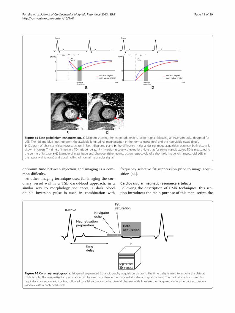
Figure 15 Late gadolinium enhancement. a) Diagram showing the magnitude reconstruction signal following an inversion pulse designed forLGE. The red and blue lines represent the available longitudinal magnetisation in the normal tissue (red) and the non-viable tissue (blue).b) Diagram of phase-sensitive reconstruction. In both diagrams a and b, the difference in signal during image acquisition between both tissues isshown in green. TI - time of inversion, TD - trigger delay, IR - inversion recovery preparation. Note that for some manufacturers TD is measured tothe centre of k-space. c-d) Example of magnitude and phase-sensitive reconstruction respectively of a short-axis image with myocardial LGE inthe lateral wall (arrows) and good nulling of normal myocardial signal.
Ferreira et al. Journal of Cardiovascular Magnetic Resonance 2013, 15:41 Page 13 of 39http://jcmr-online.com/content/15/1/41
optimum time between injection and imaging is a com-mon difficulty.Another imaging technique used for imaging the cor-
onary vessel wall is a TSE dark-blood approach; in asimilar way to morphology sequences, a dark blooddouble inversion pulse is used in combination with
Figure 16 Coronary angiography. Triggered segmented 3D angiographymid-diastole. The magnetisation preparation can be used to enhance the mrespiratory correction and control, followed by a fat saturation pulse. Severwindow within each heart-cycle.
frequency selective fat suppression prior to image acqui-sition [44].
Cardiovascular magnetic resonance artefactsFollowing the description of CMR techniques, this sec-tion introduces the main purpose of this manuscript, the
acquisition diagram. The time delay is used to acquire the data atyocardial-to-blood signal contrast. The navigator echo is used for
al phase-encode lines are then acquired during the data acquisition

Ferreira et al. Journal of Cardiovascular Magnetic Resonance 2013, 15:41 Page 14 of 39http://jcmr-online.com/content/15/1/41
description of the most common and problematic arte-facts in CMR. The causes of these include motion (re-spiratory, cardiac, and blood flow); Gibbs ringing; aliasing;chemical-shift; and B0-inhomogeneities. In the followingsections these different artefact sources will be discussedwith particular regard to their physical basis and implica-tions for the different sequences and applications.
MotionThe overall motion of the heart is a complex mixture ofcardiac motion associated with its cyclic pumping andrespiratory motion which results in an additional twist-ing and volumetric distortion. The respiratory motion isrelatively unpredictable and can vary considerably fromperson to person and from time to time. Cardiac motionhas been reasonably well controlled over the years bydetecting the QRS complex of the ECG and triggeringthe acquisition at a certain delay following this. Obvi-ously ECG triggering works best when there is low vari-ation between beats; as discussed later, arrhythmias andectopic hearts will cause artefacts.The respiratory motion has in recent years been
largely controlled by acquiring the data over the periodof a breath-hold, although this can translate into a longacquisition window within the cardiac cycle, thus poten-tially including periods of more rapid cardiac motion.Restricting the acquisition to a period of mid diastolewhere the heart is reasonably still is sometimes not feas-ible during a breath-hold, especially for patients thathave considerable problems in holding their breath lon-ger than a few seconds. For patients with very rapidheart-rates it can also be difficult to find a “motion free”acquisition window. Respiratory gating is another tech-nique that allows the removal of gross respiratory mo-tion artefacts by restricting data acquisition to theexpiratory pause, this enables longer scans with shorteracquisition windows within the cardiac cycle, which inturn reduces cardiac motion problems. Respiratory gat-ing is most commonly used in 3D imaging, in particularin imaging of the coronary arteries due to the highspatial-resolution (larger data acquisition matrices) andcoverage required. The imaging time makes breath-holdimaging impracticable.A moving object will change both the phase and mag-
nitude of its k-space components. Motion during imageacquisition will therefore introduce artefacts, and thesecan be divided into two categories, motion during theacquisition of one phase-encode line intra-view, and mo-tion between different phase-encode lines inter-view. Formost sequences intra-view motion at typical myocardialand respiratory speeds can be ignored, although rapidblood flow in major vessels can be an issue. Inter-viewmotion artefacts can be caused by cardiac motion and or
breathing motion and are very dependent on the natureof the motion in relation to the k-space coverage.Artefacts can also be created by motion between dif-
ferent components of the sequence, for example betweenthe timing of preparation pulses and image acquisitionfor a black-blood sequence. The next subsections de-scribe the basics of motion artefacts introduced in car-diac studies by breathing motion, cardiac motion, andblood flow.
Breathing motionMost cardiac sequences are segmented, i.e. the acquisi-tion of one image is divided into multiple heartbeatsand the acquisition window in each heartbeat is re-stricted, in order to reduce cardiac motion artefacts andblurring. On the other hand, respiratory motion intro-duces k-space inconsistencies between different seg-ments. Breathing artefacts will depend on the phase-encoding order used, and the timing of the motion. If,for example, motion only occurred when sampling theedges of k-space, then motion artefacts would result inblurring of the edges of the moving object in the phaseencoding direction. If, on the other hand, the centralregions of k-space were affected then this would resultin a more significant ghosting and image degradation(Figure 17). In general if breathing motion is periodicduring the acquisition of k-space in the phase encodedirection, it results in a number of defined “ghost” arte-facts distributed in that direction on the image. As canbe seen from Figure 17, for acquisition sequences thatemploy an interleaved segmented coverage of k-spacethen a single movement or drift in the respiratory pos-ition will have a similar impact to periodic breathingmotion. On the other hand for sequences that acquirek-space in a block sequential manner a single move-ment, as long as it doesn’t coincide with the centre of k-space, or similarly a drift in position, will cause someblurring but will generally cause less impact throughghosting. Different segmented sequences have differentoptimal phase-encoding orders, and therefore will be af-fected by respiratory motion differently. Generally, toavoid sudden signal amplitude and or phase discontinu-ities through k-space, which would lead to other arte-facts, the Turbo-Spin-Echo and conventional gradientecho sequences acquire the data with an interleavedmanner and the balanced SSFP sequences acquire in ablock sequential manner. However, it should be notedthat the exact methods may vary between manufac-turers and even for the same manufacturer over time.To avoid breathing motion artefact problems, the total
imaging time is kept short, and suitable for a breath-hold. If the patient is unable to hold their breath, thetotal imaging time needs to be reduced. Possible solu-tions include the use of parallel imaging, although the
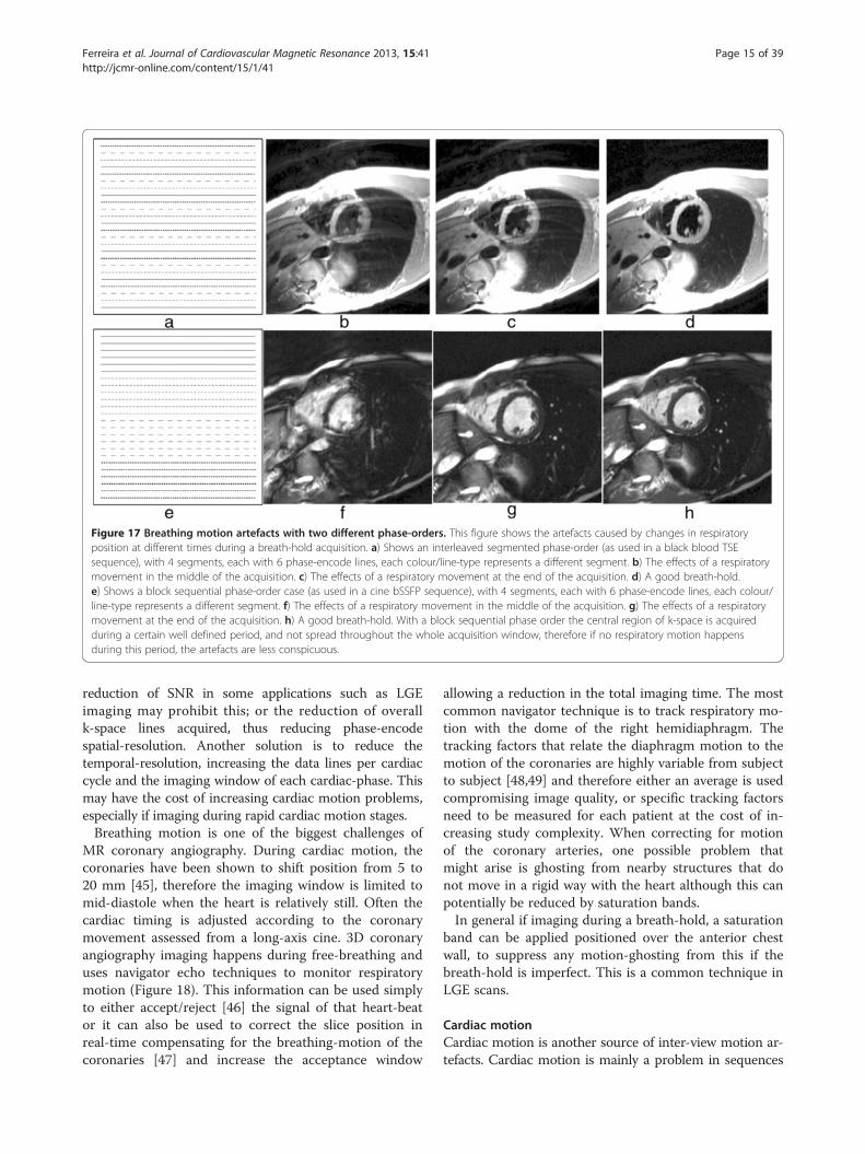
Figure 17 Breathing motion artefacts with two different phase-orders. This figure shows the artefacts caused by changes in respiratoryposition at different times during a breath-hold acquisition. a) Shows an interleaved segmented phase-order (as used in a black blood TSEsequence), with 4 segments, each with 6 phase-encode lines, each colour/line-type represents a different segment. b) The effects of a respiratorymovement in the middle of the acquisition. c) The effects of a respiratory movement at the end of the acquisition. d) A good breath-hold.e) Shows a block sequential phase-order case (as used in a cine bSSFP sequence), with 4 segments, each with 6 phase-encode lines, each colour/line-type represents a different segment. f) The effects of a respiratory movement in the middle of the acquisition. g) The effects of a respiratorymovement at the end of the acquisition. h) A good breath-hold. With a block sequential phase order the central region of k-space is acquiredduring a certain well defined period, and not spread throughout the whole acquisition window, therefore if no respiratory motion happensduring this period, the artefacts are less conspicuous.
Ferreira et al. Journal of Cardiovascular Magnetic Resonance 2013, 15:41 Page 15 of 39http://jcmr-online.com/content/15/1/41
reduction of SNR in some applications such as LGEimaging may prohibit this; or the reduction of overallk-space lines acquired, thus reducing phase-encodespatial-resolution. Another solution is to reduce thetemporal-resolution, increasing the data lines per cardiaccycle and the imaging window of each cardiac-phase. Thismay have the cost of increasing cardiac motion problems,especially if imaging during rapid cardiac motion stages.Breathing motion is one of the biggest challenges of
MR coronary angiography. During cardiac motion, thecoronaries have been shown to shift position from 5 to20 mm [45], therefore the imaging window is limited tomid-diastole when the heart is relatively still. Often thecardiac timing is adjusted according to the coronarymovement assessed from a long-axis cine. 3D coronaryangiography imaging happens during free-breathing anduses navigator echo techniques to monitor respiratorymotion (Figure 18). This information can be used simplyto either accept/reject [46] the signal of that heart-beator it can also be used to correct the slice position inreal-time compensating for the breathing-motion of thecoronaries [47] and increase the acceptance window
allowing a reduction in the total imaging time. The mostcommon navigator technique is to track respiratory mo-tion with the dome of the right hemidiaphragm. Thetracking factors that relate the diaphragm motion to themotion of the coronaries are highly variable from subjectto subject [48,49] and therefore either an average is usedcompromising image quality, or specific tracking factorsneed to be measured for each patient at the cost of in-creasing study complexity. When correcting for motionof the coronary arteries, one possible problem thatmight arise is ghosting from nearby structures that donot move in a rigid way with the heart although this canpotentially be reduced by saturation bands.In general if imaging during a breath-hold, a saturation
band can be applied positioned over the anterior chestwall, to suppress any motion-ghosting from this if thebreath-hold is imperfect. This is a common technique inLGE scans.
Cardiac motionCardiac motion is another source of inter-view motion ar-tefacts. Cardiac motion is mainly a problem in sequences

Figure 18 Right coronary imaging with cardiac motion artefacts. Magnitude images from a phase-velocity mapping study of the rightcoronary artery (arrows) acquired during systole. a) Breath-hold with long acquisition window during each cardiac-cycle, b) Retrospectiverespiratory gated with shorter acquisition window during each cardiac-cycle. Image a is considerably degraded due to cardiac motion in thelonger acquisition window. (Adapted and reprinted, with permission, from reference [50]).
Ferreira et al. Journal of Cardiovascular Magnetic Resonance 2013, 15:41 Page 16 of 39http://jcmr-online.com/content/15/1/41
where the data acquisition window includes periods ofrapid cardiac motion. Blurring can be caused by motionduring acquisition of a long segment as illustrated for cor-onary motion in Figure 18a.Another good example is first-pass myocardial perfu-
sion imaging, where several images are fully acquiredduring each heartbeat; therefore image acquisition win-dows are long and spread across the whole of the cardiaccycle, including rapid cardiac motion stages. The heartwill go through contraction and expansion as differentphase-encode lines are acquired; motion happens bothin-plane and through-plane, resulting in artefacts. Ac-quisition windows for one perfusion image are approxi-mately 100 ms for GRE and bSSFP sequences and 70 msfor h-EPI, with parallel imaging with an acceleration fac-tor of 2.For a Cartesian sequential phase-order, a continuous
motion results in banding artefacts next to sharp edges[51], which looks similar to Gibbs artefacts (describedlater). These motion artefacts are illustrated using a nu-merical simulation and an in vivo example in Figure 19for first-pass myocardial perfusion. Therefore for GREand bSSFP sequences that typically use this phase-order,motion ringing artefacts can be superimposed withGibbs (see Gibbs Ringing section) and possibly mimicreal subendocardial perfusion defects during first-pass.The motion ringing magnitude is dependent on the sig-nal difference across the edges, motion artefacts are thusexpected to be problematic during first-pass when thereis a large contrast between the LV blood pool and themyocardium. The subendocardial dark rim artefacts cre-ated by motion ringing are typically darker than the onescreated by Gibbs ringing [52].
As discussed earlier the h-EPI perfusion sequence iscommonly used with a centric interleaved phase-ordertailored for perfusion [36], minimising the effective TE.This sequence is the most robust to motion artefacts,not only because it is the fastest of the three most com-mon perfusion sequences, but also because of its differ-ent phase-order; cardiac motion artefacts do not resultin subendocardial dark rim artefacts, but in dark ghost-ing of the endocardial border along the phase-encodedirection (Figure 20). The centric interleaved phaseorder is thus useful to differentiate cardiac motion arte-facts but it also makes the h-EPI sequence very sensitiveto frequency-offsets as described below.In general, whatever the k-space acquisition scheme,
in order to minimise cardiac motion artefacts it is im-portant to keep the image acquisition time as short aspossible in each heartbeat. Possible approaches, there-fore, include using a fast EPI readout, and/or parallel im-aging. Another solution is to aim imaging for timings ofthe heart-cycle where the heart is relatively still, al-though in some applications such as multi-slice myocar-dial perfusion imaging this is not possible for all slices,especially when patients are under stress with increasedheart-rates. Also, for this specific application the slice-order could result in some slices being more motionaffected than others. This slice-order, however, is notgenerally under the control of the scan operator.The inversion pulse preparations used in dark-blood
imaging or LGE are particularly sensitive to cardiac mo-tion and arrhythmias. For the multiple inversion pulsepreparation used in dark-blood imaging, a correct car-diac cycle synchronisation with the readout is important.If during image acquisition, the heart is not in the same

Figure 19 Myocardial perfusion and cardiac motion artefacts (sequential phase-order). a) Numerical simulations of a short-axis image(including Gibbs ringing) with no in-plane motion. b) Same as a but with in-plane cardiac motion (myocardial radial contraction) with asequential phase-order acquisition. c) In vivo short-axis image of a perfusion scan with a bSSFP sequence with a sequential phase-orderacquisition. A subendocardial dark rim artefact is visible likely to be a superposition of motion and Gibbs ringing artefacts (arrows). d) Same asc but after first-pass; the contrast between the LV and myocardial signal is reduced and the dark rim artefact is no longer visible.
Ferreira et al. Journal of Cardiovascular Magnetic Resonance 2013, 15:41 Page 17 of 39http://jcmr-online.com/content/15/1/41
position as when the double-inversion pulses were ap-plied then the myocardial signal can be affected. For ex-ample if the inversion pulses occur during systole orearly-diastole and the image readout occurs during latediastole then the myocardial wall signal destined to be inthe resultant image-slice might be at least partiallysuppressed by not having been entirely re-inverted bythe spatially-selective inversion pulse (Figure 21a). Toreduce the potential for this the spatially selective inver-sion pulse thickness is commonly bigger than the image-slice thickness by a factor of two or three. The trade-offis the re-inversion of blood outside the image-slice po-tentially reducing the blood signal nulling efficiency forslow flow, which may be a factor for patients with an ab-normally low cardiac function. Motion-tracking and off-setting the preparation pulses from the imaging slicehave been shown to significantly improve image quality,especially in basal slices (high longitudinal displace-ments) without the need to increase the slice thickness[53]. Another reason for reduced blood signal nulling ef-ficiency would be an inversion time that was either too
long or too short (Figure 21b). Although it is not alwayspossible to change all the parameters required, it is nor-mally possible to adjust the trigger delay and inversiontime to change the timings of the preparation and imaging.It should be noted that the terminology for these timingparameters vary from one manufacturer to another.Arrhythmia in LGE can lead to poor image quality due
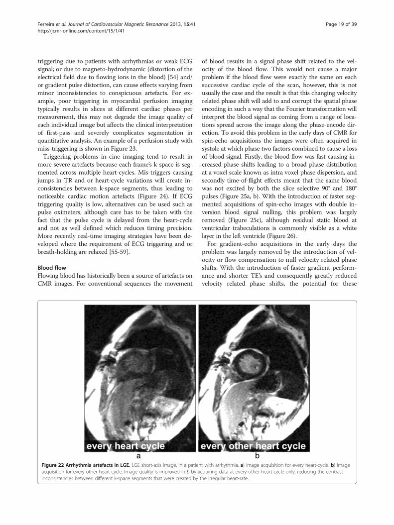
to contrast inconsistencies between different k-spacesegments, due to variations in the TR for the inversionrecovery sequence, thus leading to different amounts ofrecovery and therefore different levels of magnetisationbefore and after the inversion pulse. For this reason datais usually acquired for every other heart-beat, reducingdependency on a regular heart cycle but increasing im-aging time (Figure 22). For patients with very fast heart-rates it might be required to trigger every 3 heart-cyclesin order to guarantee good image quality.Poor cardiac triggering can also result in motion arte-
facts. Most cardiac imaging techniques require the acqui-sition of full images or k-space segments at specificcardiac phases, i.e. at specific times after the R-wave. Poor

Figure 20 Myocardial perfusion and cardiac motion artefacts (centric-interleaved phase-order). a) Numerical simulations of a short-axisimage (including Gibbs ringing) with no in-plane motion. b) Same as a but with in-plane cardiac motion (myocardial radial contraction) with acentric-interleaved phase-order acquisition. c) In vivo short-axis image of a perfusion scan with an h-EPI sequence with a centric-interleavedphase-order acquisition. A typical motion artefact is visible in the septal wall. This is no longer a subendocardial dark rim as shown in theprevious Figure for a sequential phase-order, but ghosting from the endocardial border offset along the phase-encode direction (arrows), similarto the numerical simulation shown in b. d) As in the previous Figure, motion artefacts are no longer visible after first-pass due to the reduction ofsignal contrast between the LV and myocardium.
Figure 21 Dark-blood imaging with cardiac motion artefacts. a) Myocardial signal loss (arrow) due to incomplete re-inversion of themyocardial magnetisation. b) Partial blood signal (arrow) due to incorrect inversion time of the blood magnetisation. c) Good blood signalnulling, without loss of myocardial signal. In this last example the inversion pulse thickness and timing were optimal for darkening theblood signal.
Ferreira et al. Journal of Cardiovascular Magnetic Resonance 2013, 15:41 Page 18 of 39http://jcmr-online.com/content/15/1/41
Ferreira et al. Journal of Cardiovascular Magnetic Resonance 2013, 15:41 Page 19 of 39http://jcmr-online.com/content/15/1/41
triggering due to patients with arrhythmias or weak ECGsignal; or due to magneto-hydrodynamic (distortion of theelectrical field due to flowing ions in the blood) [54] and/or gradient pulse distortion, can cause effects varying fromminor inconsistencies to conspicuous artefacts. For ex-ample, poor triggering in myocardial perfusion imagingtypically results in slices at different cardiac phases permeasurement, this may not degrade the image quality ofeach individual image but affects the clinical interpretationof first-pass and severely complicates segmentation inquantitative analysis. An example of a perfusion study withmiss-triggering is shown in Figure 23.Triggering problems in cine imaging tend to result in
more severe artefacts because each frame’s k-space is seg-mented across multiple heart-cycles. Mis-triggers causingjumps in TR and or heart-cycle variations will create in-consistencies between k-space segments, thus leading tonoticeable cardiac motion artefacts (Figure 24). If ECGtriggering quality is low, alternatives can be used such aspulse oximeters, although care has to be taken with thefact that the pulse cycle is delayed from the heart-cycleand not as well defined which reduces timing precision.More recently real-time imaging strategies have been de-veloped where the requirement of ECG triggering and orbreath-holding are relaxed [55-59].
Blood flowFlowing blood has historically been a source of artefacts onCMR images. For conventional sequences the movement
Figure 22 Arrhythmia artefacts in LGE. LGE short-axis image, in a patienacquisition for every other heart-cycle. Image quality is improved in b by ainconsistencies between different k-space segments that were created by t
of blood results in a signal phase shift related to the vel-ocity of the blood flow. This would not cause a majorproblem if the blood flow were exactly the same on eachsuccessive cardiac cycle of the scan, however, this is notusually the case and the result is that this changing velocityrelated phase shift will add to and corrupt the spatial phaseencoding in such a way that the Fourier transformation willinterpret the blood signal as coming from a range of loca-tions spread across the image along the phase-encode dir-ection. To avoid this problem in the early days of CMR forspin-echo acquisitions the images were often acquired insystole at which phase two factors combined to cause a lossof blood signal. Firstly, the blood flow was fast causing in-creased phase shifts leading to a broad phase distributionat a voxel scale known as intra voxel phase dispersion, andsecondly time-of-flight effects meant that the same bloodwas not excited by both the slice selective 90° and 180°pulses (Figure 25a, b). With the introduction of faster seg-mented acquisitions of spin-echo images with double in-version blood signal nulling, this problem was largelyremoved (Figure 25c), although residual static blood atventricular trabeculations is commonly visible as a whitelayer in the left ventricle (Figure 26).For gradient-echo acquisitions in the early days the
problem was largely removed by the introduction of vel-ocity or flow compensation to null velocity related phaseshifts. With the introduction of faster gradient perform-ance and shorter TE’s and consequently greatly reducedvelocity related phase shifts, the potential for these
t with arrhythmia. a) Image acquisition for every heart-cycle. b) Imagecquiring data at every other heart-cycle only, reducing the contrasthe irregular heart-rate.

Figure 23 ECG miss-triggering in myocardial perfusion. Mid-short-axis slice during a perfusion series. For some frames (31 and 45) the imagehas been acquired during a different (more rapidly-moving) part of the heart cycle due to ECG miss-triggering.
Ferreira et al. Journal of Cardiovascular Magnetic Resonance 2013, 15:41 Page 20 of 39http://jcmr-online.com/content/15/1/41
artefacts has been reduced, although velocity compensa-tion is still an option to minimise the problem. As a con-sequence of some cardiovascular diseases, however, theblood flow often becomes much more complex and tur-bulent and contains higher orders of motion than simplevelocity, (acceleration, jerk, etc). These higher orders offlow motion can introduce phase shifts even to a velocitycompensated sequence and the spatial scale of this mo-tion is such that this can also lead to significant phasedispersion. This intra-voxel phase dispersion effect isdependent on the TE. Although this signal loss artefacthas been found useful by some to assess the severity andform of defective heart valves (Figure 27) it should beused with caution as the area of signal loss may not bedirectly related to the severity of the valve stenosis.
Gibbs ringingGibbs ringing, also known as a truncation artefact, ispresent in every unfiltered MRI image and results fromthe fact that there is only enough time to acquire a finiteregion of k-space for each image. When the sampled sig-nal is truncated at the k-space edge and then this k-space is inverse Fourier transformed into the image,ringing will unavoidably be present at high-contrastsharp edges of structures on the image. The ringing is aknown mathematical limitation of the Fourier transform.
Figure 24 ECG miss-triggering bSSFP cine. Short-axis bSSFP cine framereduced artefacts due to a more stable RR-interval.
The two pixels either side of and closest to the edgewill show a maximal undershoot and overshoot of thetrue signal. The magnitude of the under/overshoot canbe shown mathematically to be approximately 9% of theedge signal difference; the ringing magnitude is thusdependent on the signal difference at the edge, thehigher the signal discontinuity the higher the under/overshoot (Figure 28a). Gibbs ringing also scales withpixel size, i.e. the higher the spatial-resolution the thin-ner the ringing, but the under/overshoot magnitude doesnot change with spatial-resolution (Figure 28b). Theringing visibility is also dependent on the edge positioninside the pixel [60] (unless zero-filling is applied ink-space for interpolation, when the effect appearsconsistently).Gibbs ringing is present in all unfiltered MRI images,
but it is especially problematic in certain applications suchas myocardial first-pass perfusion studies where to reduceacquisition time the spatial-resolution is low. Gibbs ring-ing can mimic a real subendocardial perfusion defect dur-ing first-pass due to the large signal discontinuity betweenthe bright LV blood pool and the darker myocardium [61](Figure 29d-e). Figure 29f shows an example of suspectedGibbs ringing in a short-axis frame of a bSSFP cine.One way of reducing Gibbs artefacts is by filtering the
k-space data of the image, a process usually known as
imaged twice: a) with significant arrhythmia artefacts and b) with
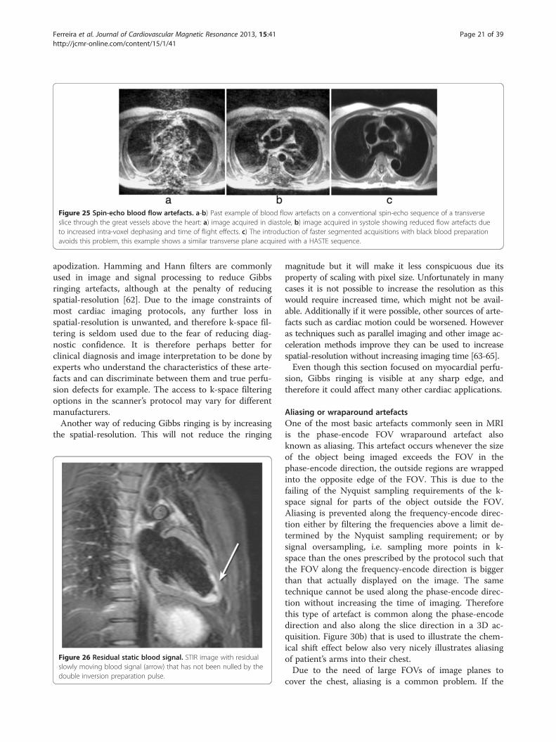
Figure 25 Spin-echo blood flow artefacts. a-b) Past example of blood flow artefacts on a conventional spin-echo sequence of a transverseslice through the great vessels above the heart: a) image acquired in diastole, b) image acquired in systole showing reduced flow artefacts dueto increased intra-voxel dephasing and time of flight effects. c) The introduction of faster segmented acquisitions with black blood preparationavoids this problem, this example shows a similar transverse plane acquired with a HASTE sequence.
Ferreira et al. Journal of Cardiovascular Magnetic Resonance 2013, 15:41 Page 21 of 39http://jcmr-online.com/content/15/1/41
apodization. Hamming and Hann filters are commonlyused in image and signal processing to reduce Gibbsringing artefacts, although at the penalty of reducingspatial-resolution [62]. Due to the image constraints ofmost cardiac imaging protocols, any further loss inspatial-resolution is unwanted, and therefore k-space fil-tering is seldom used due to the fear of reducing diag-nostic confidence. It is therefore perhaps better forclinical diagnosis and image interpretation to be done byexperts who understand the characteristics of these arte-facts and can discriminate between them and true perfu-sion defects for example. The access to k-space filteringoptions in the scanner’s protocol may vary for differentmanufacturers.Another way of reducing Gibbs ringing is by increasing
the spatial-resolution. This will not reduce the ringing
Figure 26 Residual static blood signal. STIR image with residualslowly moving blood signal (arrow) that has not been nulled by thedouble inversion preparation pulse.
magnitude but it will make it less conspicuous due itsproperty of scaling with pixel size. Unfortunately in manycases it is not possible to increase the resolution as thiswould require increased time, which might not be avail-able. Additionally if it were possible, other sources of arte-facts such as cardiac motion could be worsened. Howeveras techniques such as parallel imaging and other image ac-celeration methods improve they can be used to increasespatial-resolution without increasing imaging time [63-65].Even though this section focused on myocardial perfu-
sion, Gibbs ringing is visible at any sharp edge, andtherefore it could affect many other cardiac applications.
Aliasing or wraparound artefactsOne of the most basic artefacts commonly seen in MRIis the phase-encode FOV wraparound artefact alsoknown as aliasing. This artefact occurs whenever the sizeof the object being imaged exceeds the FOV in thephase-encode direction, the outside regions are wrappedinto the opposite edge of the FOV. This is due to thefailing of the Nyquist sampling requirements of the k-space signal for parts of the object outside the FOV.Aliasing is prevented along the frequency-encode direc-tion either by filtering the frequencies above a limit de-termined by the Nyquist sampling requirement; or bysignal oversampling, i.e. sampling more points in k-space than the ones prescribed by the protocol such thatthe FOV along the frequency-encode direction is biggerthan that actually displayed on the image. The sametechnique cannot be used along the phase-encode direc-tion without increasing the time of imaging. Thereforethis type of artefact is common along the phase-encodedirection and also along the slice direction in a 3D ac-quisition. Figure 30b) that is used to illustrate the chem-ical shift effect below also very nicely illustrates aliasingof patient’s arms into their chest.Due to the need of large FOVs of image planes to
cover the chest, aliasing is a common problem. If the

Figure 27 Complex flow signal loss. Two examples of a systolic frame of an horizontal long axis cine acquisition from two different patientswith insufficient mitral valves: a) GRE, b) bSSFP. The jet of signal loss caused by complex flows in the left atrium suggests mitral valveregurgitation (arrows). The bSSFP sequence is generally less sensitive to such flow related signal loss.
Ferreira et al. Journal of Cardiovascular Magnetic Resonance 2013, 15:41 Page 22 of 39http://jcmr-online.com/content/15/1/41
region of interest is small, for example the heart only, thensome wraparound can be acceptable as long as it does notsuperimpose on the heart. This keeps imaging time shortwithout sacrificing diagnosis and experienced technolo-gists commonly make careful use of this approach.Another technique to avoid or attenuate this artefact
is to use saturation bands (spatially selective saturationpulse as described earlier in the Saturation Pulse sectionunder Cardiovascular Pulse Sequences) in the regionsoutside the FOV to suppress their signal. The saturationworks well only if the signal used for the acquisition isexcited only once and immediately after the saturation,such as in the 90° excitation of the TSE sequence.Aliasing artefacts have been discussed in this section for
Cartesian sampling only. Aliasing and undersampling arte-facts are discussed further in the Artefacts Specific toAdvanced Cardiac Imaging Methods section, particularlyregarding non-cartesian trajectories and parallel imaging.
Figure 28 Gibbs ringing in a signal discontinuity. Simulations of Gibbsan edge on an image with two different signal discontinuities (blue and bland green). The higher step discontinuity (blue) will result in more conspicwith two different spatial-resolutions (red and blue). The frequency of Gibbovershoot is the same for both resolutions.
Chemical shiftThe resonance frequency of water and fat differs byapproximately 210 Hz at 1.5 T (420 Hz at 3 T), whichwill result in a number of effects. Firstly a misre-gistration between fat and water based tissues alongthe frequency-encode direction and more so along theperpendicular phase blip direction for EPI sequences.Secondly it will result in a slice excitation offset be-tween water and fat; and finally, for gradient-echo se-quences only, a possible pixel cancellation effect atwater-fat boundaries. The misresgistration in pixelsalong the frequency direction results from the factthat fat and water that are physically in the same pos-ition have different frequencies which will result in thefrequency encoding process separating them on thereconstructed image. The distance of separation willdepend on the receiver bandwidth. For example, if thebandwidth was 105 Hz/pixel then at 1.5 T their
ringing. a) Simulations of two theoretical step functions representingack). The effects of Gibbs ringing are also shown superimposed (reduous ringing (red). b) A simulation of a step function (black) sampleds ringing scales with resolution, although the amplitude of the under/

Figure 29 Gibbs ringing and myocardial perfusion. a-b) Numerical simulation of a short-axis image with an LV/myocardium signal ratio of 3:a) theoretical image with no Gibbs ringing, b) short-axis image corrupted by Gibbs ringing; notice the darker undershoot in the subendocardialborder mimicking a real perfusion defect. c) The same short-axis image corrupted by Gibbs ringing but with a lower LV/myocardium contrast tosimulate the signal after first-pass; the first Gibbs undershoot is not as dark as in b, and is usually not visible, hidden by the relatively high noiselevels of perfusion images. d-e) in vivo short-axis example: d) an example of circumferential Gibbs ringing during the first-pass of contrast, e) thesame short-axis plane after the first-pass when Gibbs ringing is no longer noticeable. f) example of Gibbs ringing in a short-axis frame of a bSSFPcine (arrow).
Ferreira et al. Journal of Cardiovascular Magnetic Resonance 2013, 15:41 Page 23 of 39http://jcmr-online.com/content/15/1/41
separation of 210 Hz would equate to 2 pixels on thereconstructed image. If the bandwidth were doubled to210 Hz then the separation would be halved to 1 pixel.Clearly the chemical shift effect is reduced by increasingthe bandwidth. This advantage, however, has to be bal-anced against the loss of SNR when increasing the band-width. In most cardiac sequences, misregistration alongthe frequency-encode direction is relatively negligible, be-cause of the use of large bandwidths for rapid sampling.However, for TSE sequences where longer readouts withlower bandwidths can be used, it is possible to see the ef-fect (Figure 30). As mentioned above, for an EPI readout,
Figure 30 TSE chemical shift artefacts. a-b) TSE image of a transverse pshift artefacts between the aortic wall and surrounding fat: a) horizontal frethe aortic wall along the frequency-encode direction (arrows). This artefactOn image b with the frequency-encode direction swapped from a, wrapar
misregistration can be a problem and can cause a consid-erable relative shift of the fat signal along the directionperpendicular to the frequency encoding. For a single shotEPI acquisition the shift can be several pixels and for atypical perfusion h-EPI sequence a chemical shift of closeto a pixel is typical. Where centric phase encoding is used,as is often the case, the shift is doubled and split into twoopposite directions producing a complicated artefact whenfat saturation is not applied correctly (Figure 31). Using asmall number of echoes per readout train and fat satur-ation pulses are common techniques to reduce chemicalshift artefacts in EPI.
lane through the great vessels above the heart, illustrating chemicalquency-encode, b) vertical frequency-encode. Artefacts are visible incan potentially be misdiagnosed as an aortic dissection in some cases.ound artefacts of the patient’s arms into the chest are also visible.

Ferreira et al. Journal of Cardiovascular Magnetic Resonance 2013, 15:41 Page 24 of 39http://jcmr-online.com/content/15/1/41
A fat and water separated imaging technique hasbeen recently published as a method of detectingintramyocardial fat [66].Another important artefact resulting from the chem-
ical shift and sometimes referred to as the Indian inkartefact, is the pixel cancellation at boundaries betweenfat and water based tissues. This occurs with gradient-echo sequences and is TE dependent such that the max-imum cancellation occurs when fat-water signals arecompletely out of phase, which first occurs at a TE ofapproximately 2.4 ms for 1.5 T (Figure 32). This is oftenprominent on bSSFP sequence images where the TR hasto be kept short enough to minimise the sensitivity ofthe sequence to field inhomogeneities and this generallyleads to a TE in the order of 2 ms (Figure 32b,c).When imaging the coronaries, the signal cancellation
artefacts can reduce the apparent diameter of the coron-ary arteries if fat signal is not properly suppressed.
B0-field inhommogeneitiesThe magnetic field is never completely homogeneousover the volume of the heart. It is possible to largely cor-rect variations by obtaining 3D field plots and calculat-ing the required shim currents, however, local field
Figure 31 h-EPI chemical shift artefact. Short-axis images acquired withturned on and off. When fat saturation pulses are used, the fat signal in thefat-saturation preparation, the fat signal in the chest wall is visible and, duedirections (arrows).
variations will remain because of the magnetic field sus-ceptibility variations around the heart.Most tissues are diamagnetic, i.e. create a magnetic
field that slightly opposes the applied magnetic field. Itis important to understand that this arises from theirelectronic (“Lenz”) diamagnetism, which is much largerthan the nuclear magnetisation we employ for MRI. Thedifferences in diamagnetism cause distortion of the mainfield at interfaces between tissues, and particularly thosebetween tissue and air such as between the heart andlungs. These B0 field inhomogeneities cause resonancefrequency offsets, where the local resonance frequencydeviates from the scanner’s centre frequency, leading tooff-resonance effects. Depending on the local geometry,and the sequence being used, this field distortion maysometimes be more intense causing artefacts such as sig-nal loss or spatial distortion.In CMR the sequences with the highest sensitivity to
magnetic field inhomogeneities are the bSSFP sequenceand sequences that employ rapid k-space acquisitiontechniques such as EPI and Spiral. The spin-echo se-quence is relatively insensitive whilst the conventionalgradient-echo sequence has sensitivity depending largelyon its TE parameter. Figure 33 illustrates the differencebetween a TE of 2 and 10 ms for distortion, signal loss,
a centric interleaved h-EPI sequence with fat-saturation preparationchest wall is efficiently suppressed (arrow). When there is noto chemical shift, is displaced approximately 4 pixels in both
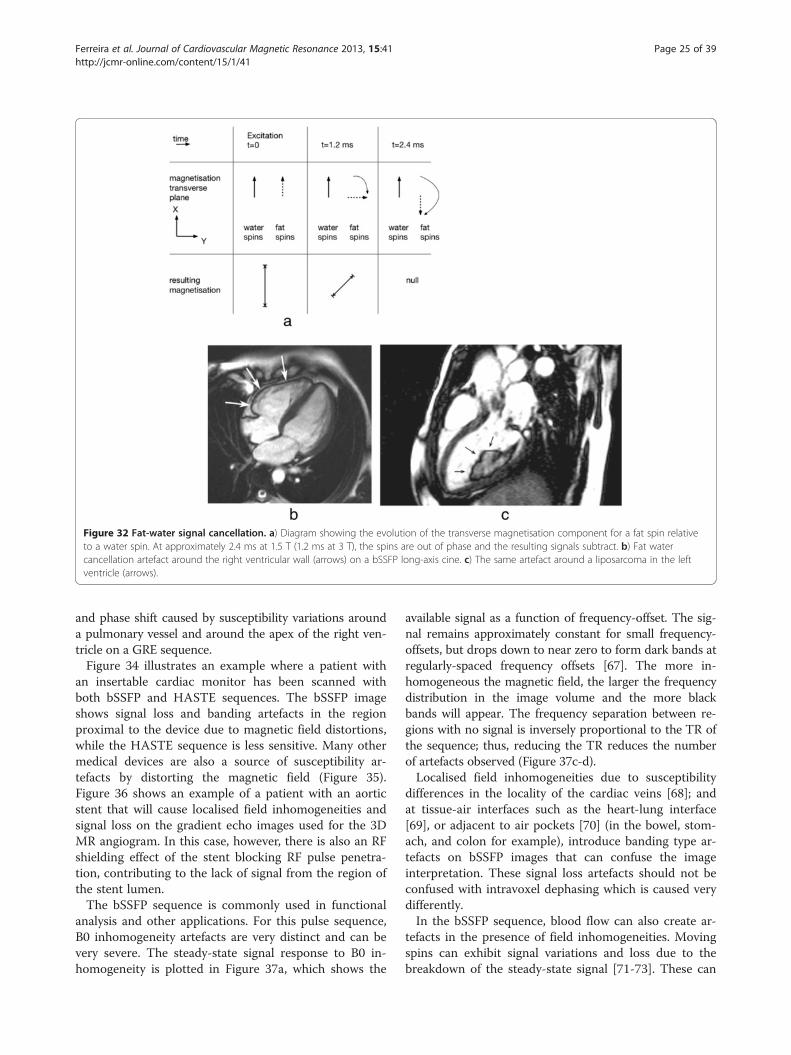
Figure 32 Fat-water signal cancellation. a) Diagram showing the evolution of the transverse magnetisation component for a fat spin relativeto a water spin. At approximately 2.4 ms at 1.5 T (1.2 ms at 3 T), the spins are out of phase and the resulting signals subtract. b) Fat watercancellation artefact around the right ventricular wall (arrows) on a bSSFP long-axis cine. c) The same artefact around a liposarcoma in the leftventricle (arrows).
Ferreira et al. Journal of Cardiovascular Magnetic Resonance 2013, 15:41 Page 25 of 39http://jcmr-online.com/content/15/1/41
and phase shift caused by susceptibility variations arounda pulmonary vessel and around the apex of the right ven-tricle on a GRE sequence.Figure 34 illustrates an example where a patient with
an insertable cardiac monitor has been scanned withboth bSSFP and HASTE sequences. The bSSFP imageshows signal loss and banding artefacts in the regionproximal to the device due to magnetic field distortions,while the HASTE sequence is less sensitive. Many othermedical devices are also a source of susceptibility ar-tefacts by distorting the magnetic field (Figure 35).Figure 36 shows an example of a patient with an aorticstent that will cause localised field inhomogeneities andsignal loss on the gradient echo images used for the 3DMR angiogram. In this case, however, there is also an RFshielding effect of the stent blocking RF pulse penetra-tion, contributing to the lack of signal from the region ofthe stent lumen.The bSSFP sequence is commonly used in functional
analysis and other applications. For this pulse sequence,B0 inhomogeneity artefacts are very distinct and can bevery severe. The steady-state signal response to B0 in-homogeneity is plotted in Figure 37a, which shows the
available signal as a function of frequency-offset. The sig-nal remains approximately constant for small frequency-offsets, but drops down to near zero to form dark bands atregularly-spaced frequency offsets [67]. The more in-homogeneous the magnetic field, the larger the frequencydistribution in the image volume and the more blackbands will appear. The frequency separation between re-gions with no signal is inversely proportional to the TR ofthe sequence; thus, reducing the TR reduces the numberof artefacts observed (Figure 37c-d).Localised field inhomogeneities due to susceptibility
differences in the locality of the cardiac veins [68]; andat tissue-air interfaces such as the heart-lung interface[69], or adjacent to air pockets [70] (in the bowel, stom-ach, and colon for example), introduce banding type ar-tefacts on bSSFP images that can confuse the imageinterpretation. These signal loss artefacts should not beconfused with intravoxel dephasing which is caused verydifferently.In the bSSFP sequence, blood flow can also create ar-
tefacts in the presence of field inhomogeneities. Movingspins can exhibit signal variations and loss due to thebreakdown of the steady-state signal [71-73]. These can
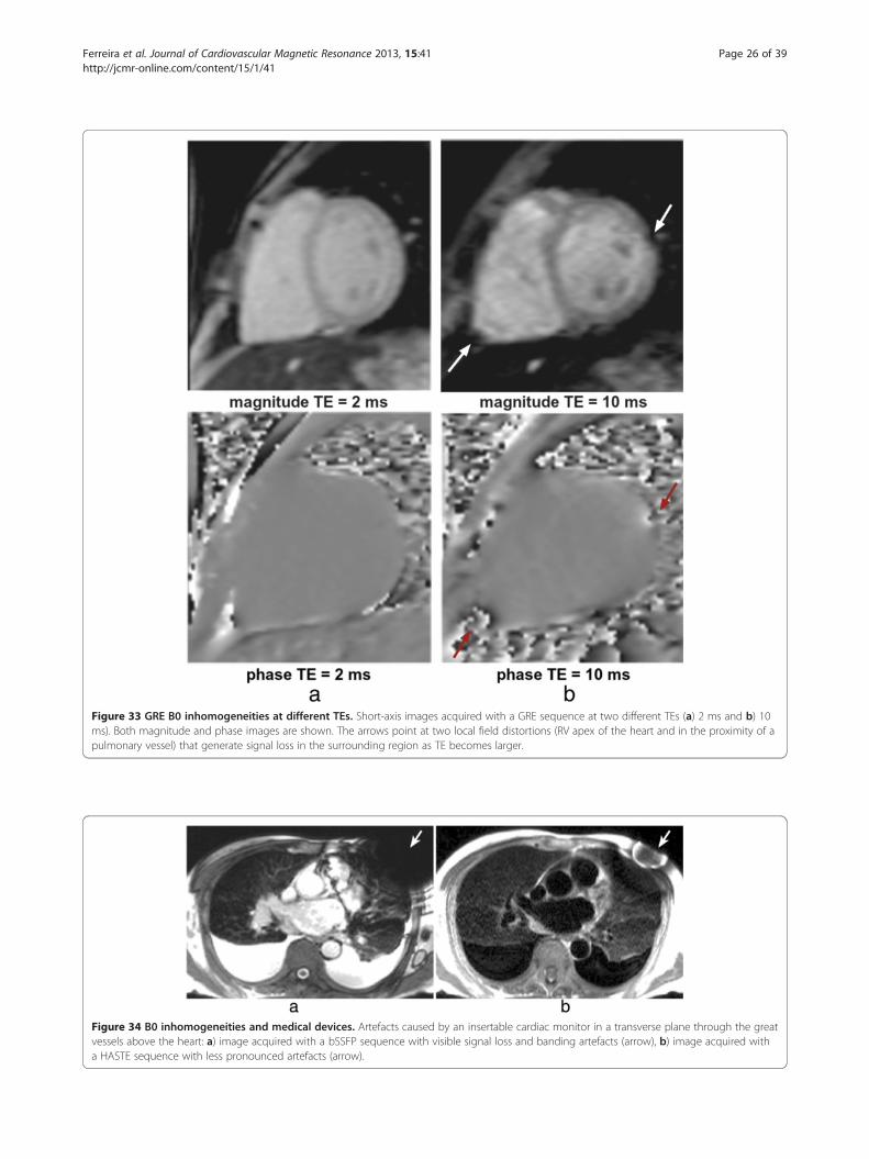
Figure 33 GRE B0 inhomogeneities at different TEs. Short-axis images acquired with a GRE sequence at two different TEs (a) 2 ms and b) 10ms). Both magnitude and phase images are shown. The arrows point at two local field distortions (RV apex of the heart and in the proximity of apulmonary vessel) that generate signal loss in the surrounding region as TE becomes larger.
Figure 34 B0 inhomogeneities and medical devices. Artefacts caused by an insertable cardiac monitor in a transverse plane through the greatvessels above the heart: a) image acquired with a bSSFP sequence with visible signal loss and banding artefacts (arrow), b) image acquired witha HASTE sequence with less pronounced artefacts (arrow).
Ferreira et al. Journal of Cardiovascular Magnetic Resonance 2013, 15:41 Page 26 of 39http://jcmr-online.com/content/15/1/41

Figure 35 B0 inhomogeneities and medical devices II. a-b) Four-chamber view acquired with GRE and bSSFP sequences respectively. Thearrows point to signal loss caused by a septal occluder. c-d) bSSFP image planes containing localised signal loss (arrows) caused by bileafletaortic and mitral valve replacements respectively.
Figure 36 B0 inhomogeneities and medical devices III. a) 3D GRE contrast-angiography maximum intensity projection reconstruction imageshowing signal loss in the descending aorta due to an aortic stent (arrow), the bottom left corner shows a bSSFP image plane containing theaortic stent; also showing signal loss in the same region (arrow). The signal void inside the stent is likely to be due to lack of RF penetrationthrough the stent wall. b) Spin-echo black-blood image also in a plane containing the aortic stent. The aortic wall outside the stent is clearlyseen (arrow).
Ferreira et al. Journal of Cardiovascular Magnetic Resonance 2013, 15:41 Page 27 of 39http://jcmr-online.com/content/15/1/41

Figure 37 bSSFP and B0 inhomogeneities. a) bSSFP steady-state signal as a function of frequency-offsets (RF flip angle 50 degrees, TR 2.2 ms).The signal is approximately constant except at multiples of ≈±227 Hz where the signal drops down to near zero, forming dark bands in theseregions. b) Spherical phantom imaged with a bSFFP sequence with an homogenous B0. c) Phantom image repeated with a field gradient fromleft to right. Dark bands are formed where the frequency offsets are multiples of ≈±227 Hz. d) Similar to c but with a TR twice as large, halvingthe distance between dark bands as a result.
Ferreira et al. Journal of Cardiovascular Magnetic Resonance 2013, 15:41 Page 28 of 39http://jcmr-online.com/content/15/1/41
occur due to in-plane flow moving through an off-resonance region, but also for through-plane flow leav-ing the image plane into such a region (Figure 38).More dark bands and signal variation artefact are
displayed in Figure 39. If a black band or flow in thepresence of field inhomogeneities artefacts affect animage then it is possible to move and or suppress theseby reacquiring with a slight frequency offset (≈ 50Hz) ofthe scanner centre-frequency. It should be recognised,however, that as one black band moves out of the heartthen another may be moving in from the other side(Figure 39d). Another example of frequency retuning isshown in Figure 40 for a patient with an air pocket inthe colon. Artefacts can thus be reduced by better shim-ming of the field in and around the heart and with local-ised centre-frequency adjustments. It is also sometimescrucial with such localised adjustments to understandthat they are not confined to the slice thickness; in thesituation where through-plane flow or motion is large,then the shim adjustment should include sufficient dis-tance perpendicular to the plane to allow it to obtainhomogeneous field volume around the slice (Figure 41).
Another technique known as wideband bSSFP [74] canalso be used to reduce the dark band artefact, althoughwith increasing scanning time.Field inhomogeneities are also an important source of
artefacts for the less widely-used EPI sequences. Se-quences with an EPI readout tend to be used in a hybridapproach (h-EPI), in order to keep the readout train rea-sonably short, thus minimising blurring, ghosting, imagedistortion, and chemical shift artefacts. h-EPI sequencesare commonly used with an interleaved phase-order.Frequency offsets will introduce phase variations in astepwise fashion, which can lead to artefacts such asblurring, and ghosting.Magnetic field inhomogeneities caused by the arrival of
a strong paramagnetic susceptibility contrast agent in theheart are commonly attributed as a possible mechanismfor dark rim artefacts in myocardial perfusion imaging.The frequency offsets introduced in the myocardium bythe first-pass of a Gadolinium-based contrast agent havebeen measured at rest and shown to be insignificant forintra-voxel signal dephasing in the myocardium at 1.5 T[75], although when combined with other sources of field

Figure 38 bSSFP and B0 inhomogeneities: blood flow and dark bands. Two bSSFP cines with two examples of off-resonance artefacts andthe effects of blood flow, the acquisition time after the R wave is also shown for each image. a) A dark band is visible in the heart (arrows), itsposition varies throughout the heart cycle due to myocardial motion and blood flow. b) Dark banding and signal intensity variations are visible inthe ascending aorta (arrows) due to a dark band in the proximity of the image plane. Its effects are brought into the image plane by the flowingblood in the ascending aorta.
Ferreira et al. Journal of Cardiovascular Magnetic Resonance 2013, 15:41 Page 29 of 39http://jcmr-online.com/content/15/1/41
inhomogeneities or tuning frequency-offsets it might pro-duce artefacts such as signal loss or image degradation.The perfusion tailored h-EPI sequence has a centric inter-leaved phase-order [36], which makes it very sensitive tofrequency-offsets [76], resulting in ghosting and splittingof the image along the phase-encode direction due to itscentric sampling trajectory (Figure 42).
Figure 39 bSSFP and B0 inhomogeneities: tuning frequency. a-d) Serifrequency offsets: original (0Hz), 50Hz, 100Hz, and 150Hz. Black band and flfrequency is adjusted the artefacts are shifted away from the heart. Image(dotted arrow), as the tuning frequency is shifted. This approaching frequeplane, similar to that shown in Figure 38b) (227 ms).
In general to minimise B0-inhomogeneities, carefulshimming and especially localised scanner frequency ad-justments are advised prior to imaging.
Blood flow measurementAs described earlier, blood flow is measured by phase con-trast velocity maps, i.e. pixel maps of phase differences
es of vertical long axis bSSFP images acquired with different tuningow artefacts through the ventricle are shown (arrows). As thed shows another dark band approaching the heart from the topncy-offset causes the blood signal to be hyperintense in the image

Figure 40 bSSFP and B0 inhomogeneities: tuning frequency II. a) Long-axis bSSFP cine frame showing dark bands in the heart (arrows) dueto field distortions caused by an air pocket in the colon (not shown in this plane). b) The same frame after a manual frequency tuning. The shiftof the scanner centre-frequency removed the artefact from the LV, although signal enhancement artefacts due to blood flow from the imageplane into a dark band region are still visible in the RV (arrow).
Ferreira et al. Journal of Cardiovascular Magnetic Resonance 2013, 15:41 Page 30 of 39http://jcmr-online.com/content/15/1/41
between two reconstructed phase images each acquiredwith a different phase velocity sensitivity. Because they area map of phase difference there is an inherent maximumrange of phase (360°) and therefore a maximum range ofvelocity that can be measured. The phase sensitivity of theacquisition sequence can be adjusted according to theexpected flow velocities, however, if a larger than expectedrange of velocities is encountered then the phase rangewill be greater than ±180° and artefactual or so calledaliased velocities would be measured (Figure 43). In gen-eral, the chances of aliasing should be minimised by esti-mating a larger than expected velocity range, but at thesame time without compromising the sensitivity of thevelocity measurement.
Figure 41 Frequency and shim adjustment box. Example of the positiothe green box) shown in three anatomical slices. The dashed rectangle repappearance and application of this will vary between manufacturers.
There are a number of artefacts and measurement er-rors that can be encountered with phase contrastvelocity mapping. These include artefactual velocitymeasurements due to aliasing of signal phase as de-scribed above. Another problem is that of signal mis-registration where blood signals move between thetiming of slice selection and phase and frequency en-coding (Figure 44). This can result not only in the arte-factual positioning of the blood signal relative to thestationary ones but also artefactual velocity measure-ments due to an overlay and combining of moving andstationary spins and their phases. For similar reasonspartial volume effects where a voxel contains a mix-ture of stationary and flowing spins will result in
ning of the frequency and shim adjustment volume (represented byresents the position of the short-axis slices being acquired. The

Figure 42 h-EPI perfusion and B0 inhomogeneities. Three frames during contrast first-pass perfusion imaging in a basal short-axis planeacquired with an h-EPI sequence. This example shows severe frequency-offsets which result in blurring and ghosting (arrows) along the phaseencode direction (vertical) with this sequence. This example is extreme and uncommon, although blurring of the myocardial wall along thephase-encode direction is believed to be a more common event in first-pass perfusion with this particular sequence.
Ferreira et al. Journal of Cardiovascular Magnetic Resonance 2013, 15:41 Page 31 of 39http://jcmr-online.com/content/15/1/41
measurement errors, especially if the flowing spinshave velocity aliasing as described above.More subtle effects can cause significant errors to flow
measurements by introducing background phase shifts.Some distortion of the magnetic field gradients is un-avoidable from fundamental electromagnetism, and thisis known in MRI as Maxwell or concomitant gradients[77]. This is one cause of the background phase shiftswhich become more significant when high-strength gra-dients are used and also when imaging at lower mainfield strengths. With the latest gradient systems Maxwellgradient effects are certainly a factor for phase contrastvelocity mapping at 1.5T. The velocity maps can how-ever be corrected analytically and automatically in soft-ware with no user intervention required.A second common reason for background phase shifts
is the presence of small uncorrected side-effects of thegradient pulses in the magnet, known as eddy currents.Software is sometimes provided which allows the user toplace markers identifying stationary tissues so that thebackground phase error can be calculated and removedfrom the entire image. It has been shown previously thatsmall background errors (smaller than 1% of the velocity
Figure 43 Blood flow aliasing. Phase contrast velocity map and velocitythe heart. a) Aliased velocities are seen in the ascending aorta. b) VelocityThe offset shifts the range of velocities corresponding to black and white pnot exceed the top of the range. Although this “offset” correction usually sare surrounded by non-wrapped pixels, problems can occur in other situatflow. This results in “uncorrectable” aliasing where no amount of offset progenerally available on scanners, but is available in post image-processing s
sensitivity range (VENC)) can significantly affect mea-surements of shunt flow and cardiac output, and thatthese may occur easily on some systems [78].Voxels containing a range of velocities in the direction
encoded will suffer dephasing, resulting in a weak overallsignal which can lead to unreliable phase measurementsand therefore unreliable output from the phase subtrac-tion for the velocity image. As the velocity encodedmagnitude is often not reconstructed users should beaware of how unreliable the velocity data may be.
Late gadolinium enhancementIn LGE studies, choosing the correct inversion time (TI)to null normal myocardium can be challenging for inex-perienced operators. The time varies from patient to pa-tient and increases with time after the injection; typicalinversion times are around 200-300 ms. At the correct TI,normal myocardium is nulled, while non-viable tissue isbright. With the standard magnitude reconstruction, if TIis too short or too long then normal myocardium will notbe nulled, and the contrast between infarcted and normalmyocardium is highly reduced (Figure 45). To overcomethis problem, phase sensitive image reconstruction (PSIR)
profile from a transverse slice showing flow in the great vessels abovemeasurement corrected by “offsetting” the velocity window post-scan.ixels, in this example upwards so that the fast forward velocity doesuffices in simple cases (like this one) where pixels of wrapped velocityions where the wraparound has occurred in pixels at the edge of aduces a sensible value for the wrapped pixels. This correction is notoftware.

Figure 44 Blood flow misregistration. An old study showing an image acquired with a relatively long TE showing zero signal of the bloodflowing into the slice (arrow) and misregistration of blood signal along the ascending aorta: a) magnitude, b) phase. This effect is generally nowreduced due to shorter TEs being used, although it could still be a problem for fast moving jets of blood through stenotic valves for example.
Ferreira et al. Journal of Cardiovascular Magnetic Resonance 2013, 15:41 Page 32 of 39http://jcmr-online.com/content/15/1/41
[38] allows the normal myocardium to be effectivelynulled retrospectively whatever the TI by adjusting theimage window and level on the display.A potential phase-encode artefact in LGE imaging due
to the longitudinal magnetisation inversion recoveryduring the acquisition of multiple phase-encode lines ineach cardiac cycle has been debated [79]. The magnet-isation recovers throughout acquisition window fromnegative to positive with potential consequences to theimage. Some centres acquire “phase-encode swapped”repetitions of LGE images, partly to identify any suchartefact by its direction rotation with the phase encod-ing, but also as a safeguard to detect other potential ar-tefacts that direct themselves along the phase-encode
Figure 45 LGE: TI timing (magnitude vs PSIR). Short-axis images at variephase-sensitive. TI = 175, 200, 225, 250, 275, and 300 ms from left to right.reconstructed images, while they are consistent for the normalised phase-sreference [38]).
direction, such as those caused by respiratory motion,CSF ghosting and other factors (Figure 46).One artefact that does not only affect LGE studies but
any segmented acquisition with an inversion pulse is theghosting of fluids with a long T1. The long T1 producesa signal oscillation during its approach to the steady-state (see Gradient-Echo section), where the signal tendsto invert the magnetisation sign in alternate cycles of theacquired data resulting in ghosts along the phase-encodedirection. Ghosting of the cerebrospinal fluid (CSF)which has a very long T1 is common in LGE and STIRblack-blood studies. This is usually suppressed by apply-ing a spatial saturation band (Figure 47a-d). In the LGEexample (Figure 46a-b) the spatial location of the
d TIs for a patient with inferior MI. a-f) Magnitude, g-l) normalizedThe appearance and contrast are variable for the magnitude-ensitive reconstruction (Reprinted, with permission, from

Ferreira et al. Journal of Cardiovascular Magnetic Resonance 2013, 15:41 Page 33 of 39http://jcmr-online.com/content/15/1/41
saturation is not very clear, this is presumably because ofthe timing of the spatial saturation that cannot immedi-ately precede the imaging k-space centre and the Mz re-covery of other tissues due to gadolinium shortened T1.However, the T1 of CSF remains very long, which meansthat this stays well saturated. A possible example of thesame ghosting mechanism of a pleural effusion in aSTIR sequence is also shown in Figure 47e.
Artefacts specific to advanced cardiac imaging methodsMethods of more efficiently acquiring the MR data areof particular interest to CMR because of the compro-mises that have to be made to acquire image data in ashort time, often restricted to a fraction of one cardiaccycle or fractions of multiple cardiac cycles within abreath-hold. Methods such as non-cartesian sampling,parallel imaging, and partial-Fourier have been intro-duced to accelerate the acquisition. Although each ofthese methods may work well a proportion of the timeand in particular if extra care is taken to set up the scan,they all tend to reduce the imaging robustness and tendto produce artefacts on images and or produce artefac-tual measurements.
Parallel imaging artefactsParallel imaging accelerates image acquisition which hasthe potential to reduce some problems, for example, al-though parallel imaging introduces an SNR penalty, italso shortens the readout time which for a single shotEPI sequence for example reduces distortions caused byfield inhomogeneities, reduces blurring due to T2* andor T2 decay and reduces sensitivity to motion.SENSE and GRAPPA are two parallel imaging tech-
niques that, in theory, should yield similar results; al-though in some situations GRAPPA is more robust toartefacts because the coil sensitivity maps are generatedin k-space, and not in the image-space as for SENSE.For example, when imaging aliased FOVs, SENSE coil
Figure 46 Phase-swapping in LGE. Short-axis LGE image with phase-enccan be seen mimicking gadolinium enhancement on image a (arrow), but
sensitivity maps may also be aliased, and therefore erro-neous image reconstruction will result in incomplete un-wrapping of the aliased pixels [80] (some scannermanufacturers acquire sensitivity maps over a much lar-ger FOV than the image acquisition in order to avoidthis issue). Respiratory motion can also introduce re-construction errors due to inaccurate sensitivity maps(Figure 48) [81].
Motion with radial and spiral k-space trajectoriesSequences with non-Cartesian forms of k-space coveragesuch as radial and spiral have also been used to imagethe heart [82-88], artefacts discussed earlier can havevery different characteristics when compared to themore conventional Cartesian methods.Radial and spiral k-space acquisitions are generally
thought of as being less sensitive to motion. Radial se-quences tend to oversample the centre of k-space andthis tends to reduce the visibility of breathing artefacts[89]. For a radial acquisition instead of ghosting in thephase-encode direction as seen with Cartesian sampling,respiratory motion results in streaking artefacts propa-gating from the moving object, perpendicular to the mo-tion direction (Figure 49). For spiral sequences, motionartefacts tend to take the form of swirls and dependingon the imaging region of interest these can be less of aproblem than phase-encode ghosts. Variable-density spi-rals that oversample the centre of k-space, at a cost ofundersampling the edges, have also been shown to re-duce respiratory artefacts in segmented cine images [83].Radial sampled data can also be used to correct for mo-
tion in a self-navigating way. Different projection views (atdifferent angles) can be analysed for consistency. If motionis present, consistency will fail and the data can bediscarded and potentially resampled before reconstruction[90]. This technique uses navigator data from the heart it-self, and not from the diaphragm, eliminating any prob-lems of translating diaphragmatic motion to cardiac
ode direction: a) horizontal, b) vertical. Artefact of an unknown sourcenot on b.

Figure 47 CSF and pleural effusion ghosting. a-b) Long-axis LGE image: a) CSF ghosting is visible in the heart (arrow), b) CSF ghostingsuppressed by a saturation band placed over the spinal canal. In this example the spatial location of the saturation is not very clear, this ispresumably because of the timing of the spatial saturation that cannot immediately precede the imaging k-space centre, and the Mz recovery ofother tissues due to gadolinium shortened T1. However, the T1 of CSF remains very long, which means that this stays well saturated. c-d) STIRtransverse image: c) CSF ghost visible in the RV (arrows), d) CSF ghosting supressed by saturation band placed over the spine (arrow). e) Ghostingof the fluid in the pleural layers (pleural effusion) (arrows) in part due to its long T1. Pulsatility effects may also be present, contributing tothe ghosting.
Ferreira et al. Journal of Cardiovascular Magnetic Resonance 2013, 15:41 Page 34 of 39http://jcmr-online.com/content/15/1/41
motion. Similarly self-gating has been described using ra-dial sampling with a 1DFT projection reconstruction tomonitor the heart motion through the cardiac cycle andthen to use this for cardiac gating [91]. However, it has tobe accepted that the performance of such methods de-pends on the contents of the slice being imaged and is po-tentially less reliable than the use of ECG synchronisation.
B0 inhomogeneity with Radial and Spiral k-space trajectoriesNon-Cartesian approaches with long (>15 ms at 1.5 T)acquisitions after each RF pulse are highly sensitive to
field inhomogeneities, where generally off-resonance andchemical shift translates into image blurring in all direc-tions and signal loss (Figure 50). In spiral trajectories,blurring increases with increase in readout time of oneinterleave, i.e. with the off-resonance phase accumulatedalong each readout. Radial trajectories show geometricaland image intensity distortions in the presence of fieldinhomogeneities [92]. B0-inhomogeneity typically variesslowly over the FOV, whereas magnetic susceptibilitycan vary sharply, resulting in spatially dependent blur-ring and signal loss.

Figure 48 SENSE with aliasing artefact due to respiratory motion. Three short-axis slices during first-pass perfusion reconstructed with twodifferent coil sensitivity maps (acquisition with a bSSFP sequence and SENSE with an acceleration factor of 4). The three slices on top werereconstructed with the optimal coil sensitivity map, i.e. the coil sensitivity map acquired in the same respiratory position as the perfusion images.On the bottom the same perfusion images were reconstructed with a coil sensitivity map that was acquired in a different respiratory stage fromthe perfusion images. The reconstruction is corrupted with aliasing artefacts (arrows) due to inconsistencies between the sensitivity map and theundersampled perfusion data.
Ferreira et al. Journal of Cardiovascular Magnetic Resonance 2013, 15:41 Page 35 of 39http://jcmr-online.com/content/15/1/41
Aliasing with radial and spiral k-space trajectoriesDue to the 2D readout gradients in these trajectories,aliasing artefacts happen from all directions resulting inadditional streaks and swirls, therefore the FOV has tobe chosen with attention to aliasing in all directions. Be-cause there is no wraparound along the phase-encodedirection, mild undersampling artefacts are commonlyconsidered as a good trade-off for reduced imaging time.
EPI and nyquist ghostingThe readout of an EPI echo train also introduces a spe-cific artefact related to the alternating sampling gradi-ents. This artefact is commonly known as Nyquist ghostor N/2 artefact and it is created by a mixture of gradientimperfections [93], eddy currents, concomitant fields[94], receiver filter asymmetry [95] or susceptibility. All
Figure 49 Impact of respiratory motion on cine imaging: Cartesian vsmotion on a Cartesian vs Radial k-space acquisition. In both sampling trajeand another during free breathing. The acquisition time after the R wave fo
these factors will cause mismatches between odd andeven echoes, resulting in some signal or a “ghost” beingdisplaced half a field of view across the image alongthe phase-encode direction. These mismatches can bemeasured by acquiring at least two non-phase-encodedechoes with opposite polarity during imaging. Theacquired mismatch can then be corrected in a post-processing technique known as phase-correction,reducing the visibility of Nyquist ghosting. This correc-tion is commonly employed in EPI sequences. Whenusing h-EPI techniques with multiple excitations peracquisition, then the phase discrepancy between oddand even lines leads to multiple ghosts [96]. Figure 51shows an example of an h-EPI image with imperfectphase-correction, displaying residual Nyquist ghostingalong the phase-encode direction.
radial. Short-axis GRE cine, comparing the effects of respiratoryctories two different acquisitions were made, one during a breath-holdr each image is also shown.
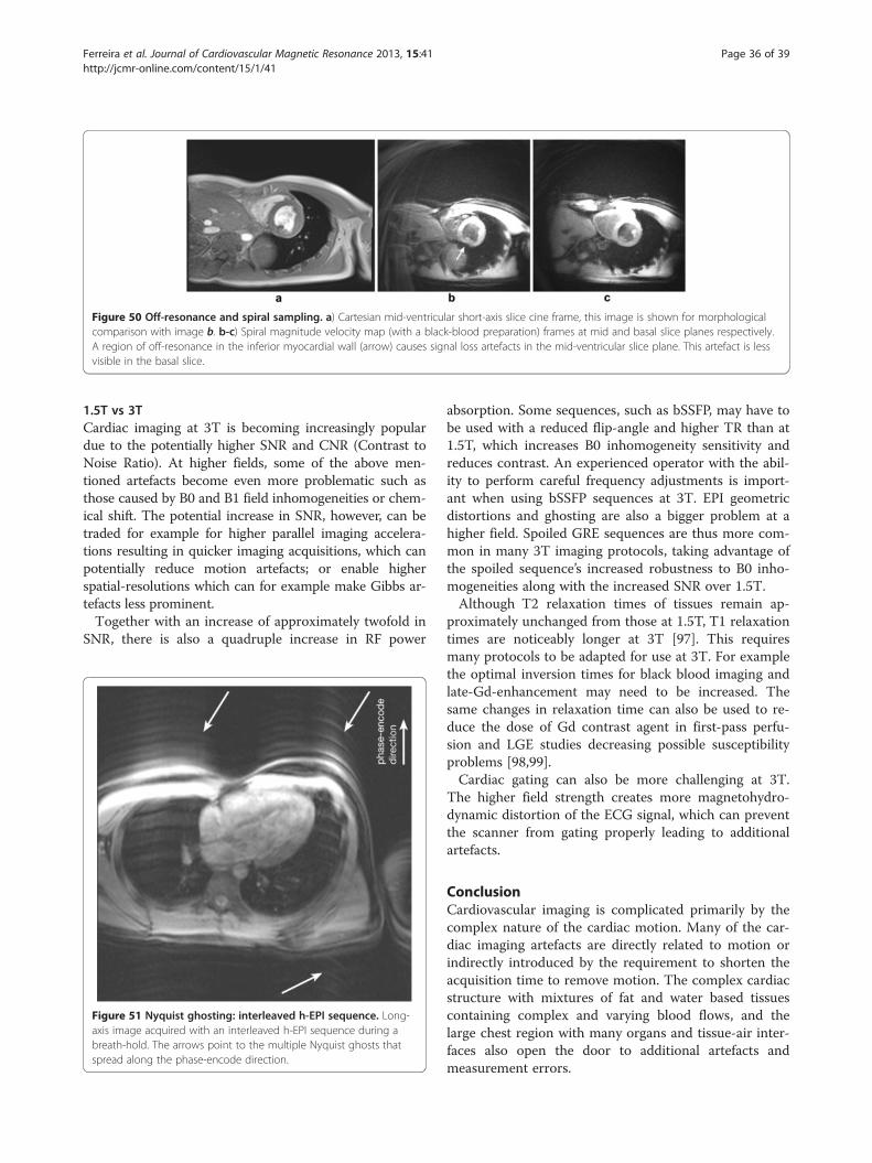
Figure 50 Off-resonance and spiral sampling. a) Cartesian mid-ventricular short-axis slice cine frame, this image is shown for morphologicalcomparison with image b. b-c) Spiral magnitude velocity map (with a black-blood preparation) frames at mid and basal slice planes respectively.A region of off-resonance in the inferior myocardial wall (arrow) causes signal loss artefacts in the mid-ventricular slice plane. This artefact is lessvisible in the basal slice.
Ferreira et al. Journal of Cardiovascular Magnetic Resonance 2013, 15:41 Page 36 of 39http://jcmr-online.com/content/15/1/41
1.5T vs 3TCardiac imaging at 3T is becoming increasingly populardue to the potentially higher SNR and CNR (Contrast toNoise Ratio). At higher fields, some of the above men-tioned artefacts become even more problematic such asthose caused by B0 and B1 field inhomogeneities or chem-ical shift. The potential increase in SNR, however, can betraded for example for higher parallel imaging accelera-tions resulting in quicker imaging acquisitions, which canpotentially reduce motion artefacts; or enable higherspatial-resolutions which can for example make Gibbs ar-tefacts less prominent.Together with an increase of approximately twofold in
SNR, there is also a quadruple increase in RF power
Figure 51 Nyquist ghosting: interleaved h-EPI sequence. Long-axis image acquired with an interleaved h-EPI sequence during abreath-hold. The arrows point to the multiple Nyquist ghosts thatspread along the phase-encode direction.
absorption. Some sequences, such as bSSFP, may have tobe used with a reduced flip-angle and higher TR than at1.5T, which increases B0 inhomogeneity sensitivity andreduces contrast. An experienced operator with the abil-ity to perform careful frequency adjustments is import-ant when using bSSFP sequences at 3T. EPI geometricdistortions and ghosting are also a bigger problem at ahigher field. Spoiled GRE sequences are thus more com-mon in many 3T imaging protocols, taking advantage ofthe spoiled sequence’s increased robustness to B0 inho-mogeneities along with the increased SNR over 1.5T.Although T2 relaxation times of tissues remain ap-
proximately unchanged from those at 1.5T, T1 relaxationtimes are noticeably longer at 3T [97]. This requiresmany protocols to be adapted for use at 3T. For examplethe optimal inversion times for black blood imaging andlate-Gd-enhancement may need to be increased. Thesame changes in relaxation time can also be used to re-duce the dose of Gd contrast agent in first-pass perfu-sion and LGE studies decreasing possible susceptibilityproblems [98,99].Cardiac gating can also be more challenging at 3T.
The higher field strength creates more magnetohydro-dynamic distortion of the ECG signal, which can preventthe scanner from gating properly leading to additionalartefacts.
ConclusionCardiovascular imaging is complicated primarily by thecomplex nature of the cardiac motion. Many of the car-diac imaging artefacts are directly related to motion orindirectly introduced by the requirement to shorten theacquisition time to remove motion. The complex cardiacstructure with mixtures of fat and water based tissuescontaining complex and varying blood flows, and thelarge chest region with many organs and tissue-air inter-faces also open the door to additional artefacts andmeasurement errors.

Ferreira et al. Journal of Cardiovascular Magnetic Resonance 2013, 15:41 Page 37 of 39http://jcmr-online.com/content/15/1/41
If we understand the physical principles behind theformation of artefacts, we should be in a position toidentify and possibly avoid them, increasing image qual-ity and interpretation.
Competing interestsThe authors declare that they have no competing interests.
Authors’ contributionsAll authors contributed in the design, intellectual conception, and revision.All authors read and approved the final manuscript.
AcknowledgementsThe authors are grateful to Dr. Jennifer Keegan for her support with thismanuscript. This work was supported by the NIHR Cardiovascular BiomedicalResearch Unit of Royal Brompton and Harefield NHS Foundation Trust andImperial College London UK.
Received: 17 July 2012 Accepted: 17 April 2013Published: 22 May 2013
References1. Smith T, Nayak K. MRI artifacts and correction strategies. Imaging Med.
2010; 2(4):445–57.2. Saremi F, Grizzard JD, Kim RJ. Optimizing cardiac MR imaging: practical
remedies for artifacts. Radiographics. 2008; 28(4):1161–87.3. McRobbie DW, Moore EA, Graves MJ, Prince MR. Chapter 6: Improving
your image: how to avoid artefacts. In: MRI from Picture to Proton. 2nd ed.Cambridge University Press; 2006: p. 79–107.
4. Ridgway JP. Cardiovascular magnetic resonance physics for clinicians:part I. J CardiovascMagn Reson. 2010; 12:71.
5. Biglands JD, Radjenovic A, Ridgway JP. Cardiovascular magnetic resonancephysics for clinicians: Part II. J Cardiovasc Magn Reson. 2012; 14:66.
6. Zur Y, Wood ML, Neuringer LJ. Spoiling of transverse magnetization insteady-state sequences. Magn Reson Med. 1991; 21(2):251–63.
7. Levitt MH. Composite pulses. Prog Nucl Magn Reson Spectrosc. 1986;18:61–122.
8. Ugurbil K, Garwood MBM. Amplitude and frequency modulated pulses toachieve 90 plane rotations with inhomogeneous B1 fields. J Magn Reson.1987; 72:177–85.
9. Axel L, Dougherty L. MR imaging of motion with spatial modulation ofmagnetization. Radiology. 1989; 171(3):841–5.
10. Fischer SE, McKinnon GC, Maier SE, Boesiger P. Improved myocardialtagging contrast. Magn Reson Med. 1993; 30(2):191–200.
11. Lauterbur PC. Image formation by induced local interactions, examplesemploying nuclear magnetic resonance. Nature. 1973; 242:190–1.
12. Axel L, Herman GT, Roberts DA, Dougherty L. Linogram reconstruction formagnetic resonance imaging (MRI). IEEE Trans Med Imaging.1990; 9(4):447–9.
13. Pipe JG. Motion correction with propeller MRI: application to head motionand free-breathing cardiac imaging. Magn Reson Med. 1999; 42(5):963–9.
14. Feinberg DA, Hale JD, Watts JC, Kaufman L, Mark A. Halving MR imagingtime by conjugation: demonstration at 3.5 kg. Radiology. 1986;161(2):527–31.
15. Larkman DJ, Nunes RG. Parallel magnetic resonance imaging. Phys MedBiol. 2007; 52(7):R15–55.
16. Griswold MA, Jakob PM, Heidemann RM, Nittka M, Jellus V, Wang J, Kiefer B,Haase A. Generalized autocalibrating partially parallel acquisitions(GRAPPA). Magn Reson Med. 2002; 47(6):1202–10.
17. Pruessmann KP, Weiger M, Scheidegger MB, Boesiger P. SENSE: sensitivityencoding for fast MRI. Magn Reson Med. 1999; 42(5):952–62.
18. Madore B, Glover GH, Pelc NJ. Unaliasing by fourier-encoding theoverlaps using the temporal dimension (UNFOLD), applied to cardiacimaging and fMRI. Magn Reson Med. 1999; 42(5):813–28.
19. Kellman P, Epstein FH, McVeigh ER. Adaptive sensitivity encodingincorporating temporal filtering (TSENSE). Magn Reson Med. 2001;45(5):846–52.
20. Breuer FA, Kellman P, Griswold MA, Jakob PM. Dynamic autocalibratedparallel imaging using temporal grappa (TGRAPPA). Magn Reson Med.2005; 53(4):981–5.
21. Foo TK, Bernstein MA, Aisen AM, Hernandez RJ, Collick BD, Bernstein T.Improved ejection fraction and flow velocity estimates with use of viewsharing and uniform repetition time excitation with fast cardiactechniques. Radiology. 1995; 195(2):471–8.
22. Markl M, Hennig J. Phase contrast MRI with improved temporalresolution by view sharing: k-space related velocity mapping properties.Magn Reson Imaging. 2001; 19(5):669–76.
23. Simonetti OP, Finn JP, White RD, Laub G, Henry DA. "black blood" t2-weighted inversion-recovery MR imaging of the heart. Radiology. 1996;199(1):49–57.
24. Kiefer B, Grassner J, Hausman R. Image acquisition in a second with halffourier acquisition single-shot turbo spin-echo. In: Proceedings of Societyfor Magnetic Resonance; 1994.
25. Sechtem U, Pflugfelder PW, Gould RG, Cassidy MM, Higgins CB.Measurement of right and left ventricular volumes in healthy individualswith cine MR imaging. Radiology. 1987; 163(3):697–702.
26. Plein S, Bloomer TN, Ridgway JP, Jones TR, Bainbridge GJ, Sivananthan MU.Steady-state free precession magnetic resonance imaging of the heart:comparison with segmented k-space gradient-echo imaging.J Magn Reson Imaging. 2001; 14(3):230–6.
27. Barkhausen J, Ruehm SG, Goyen M, Buck T, Laub G, Debatin JF. MRevaluation of ventricular function: true fast imaging with steady-stateprecession versus fast low-angle shot cine MR imaging: feasibility study.Radiology. 2001; 219(1):264–9.
28. Thiele H, Nagel E, Paetsch I, Schnackenburg B, Bornstedt A, KouwenhovenM, Wahl A, Schuler G, Fleck E. Functional cardiac MR imaging with steady-state free precession (SSFP) significantly improves endocardial borderdelineation without contrast agents. J Magn Reson Imaging. 2001;14(4):362–7.
29. Lanzer P, Barta C, Botvinick EH, Wiesendanger HU, Modin G, Higgins CB.ECG-synchronized cardiac MR imaging: method and evaluation.Radiology. 1985; 155(3):681–6.
30. Lenz GW, Haacke EM, White RD. Retrospective cardiac gating: a review oftechnical aspects and future directions. Magn Reson Imaging. 1989;7(5):445–55.
31. Bryant DJ, Payne JA, Firmin DN, Longmore DB. Measurement of flow withNMR imaging using a gradient pulse and phase difference technique.J Comput Assist Tomogr. 1984; 8(4):588–93.
32. Nayler GL, Firmin DN, Longmore DB. Blood flow imaging by cinemagnetic resonance. J Comput Assist Tomogr. 1986; 10(5):715–22.
33. Moran PR. A flow velocity zeugmatographic interlace for NMR imaging inhumans. Magn Reson Imaging. 1982; 1(4):197–203.
34. VanDijk P. Direct cardiac NMR imaging of heart wall and blood flowvelocity. J Comput Assist Tomogr. 1984; 8(3):429–36.
35. Atkinson DJ, Burstein D, Edelman RR. First-pass cardiac perfusion:evaluation with ultrafast MR imaging. Radiology. 1990; 174(3 Pt 1):757–62.
36. Ding S, Wolff SD, Epstein FH. Improved coverage in dynamic contrast-enhanced cardiac MRI using interleaved gradient-echo EPI. Magn ResonMed. 1998; 39(4):514–9.
37. Simonetti OP, Kim RJ, Fieno DS, Hillenbrand HB, Wu E, Bundy JM, Finn JP,Judd RM. An improved MR imaging technique for the visualization ofmyocardial infarction. Radiology. 2001; 218(1):215–23.
38. Kellman P, Arai AE, McVeigh ER, Aletras AH. Phase-sensitive inversionrecovery for detecting myocardial infarction using gadolinium-delayedhyperenhancement. Magn Reson Med. 2002; 47(2):372–83.
39. Locca D, Bucciarelli-Ducci C, Lyne J, Chapparo M, Ferrante G, O’Hanlon R,Prasad S, Gatehouse P, Drivas P, Wage R, Firmin D, Pennell D. Rapidassessment of myocardial scar and viability in ischemic heart disease: acardiovascular magnetic resonance study. In: Proceedings of Society forCardiovascular Magnetic Resonance; 2009: p. 154.
40. Stuber M, Botnar RM, Danias PG, Sodickson DK, Kissinger KV, Van CauterenM, De Becker J, Manning WJ. Double-oblique free-breathing highresolution three-dimensional coronary magnetic resonance angiography.J Am CollCardiol. 1999; 34(2):524–31.
41. Regenfus M, Ropers D, Achenbach S, Schlundt C, Kessler W, Laub G, MoshageW, Daniel WG. Comparison of contrast-enhanced breath-hold and free-breathing respiratory-gated imaging in three-dimensional magneticresonance coronary angiography. Am J Cardiol. 2002; 90(7):725–30.
42. Deshpande VS, Shea SM, Chung YC, McCarthy RM, Finn JP, Li D. Breath-hold three-dimensional true-FISP imaging of coronary arteries usingasymmetric sampling. J Magn Reson Imaging. 2002; 15(4):473–8.

Ferreira et al. Journal of Cardiovascular Magnetic Resonance 2013, 15:41 Page 38 of 39http://jcmr-online.com/content/15/1/41
43. Bi X, Li D. coronary arteries at 3.0 t: Contrast-enhanced magnetization-prepared three-dimensional breathhold MR angiography. J Magn ResonImaging. 2005; 21(2):133–9.
44. Stuber M, Botnar RM, Kissinger KV, Manning WJ. Free-breathing black-blood coronary MR angiography: initial results. Radiology. 2001;219(1):278–83.
45. Al-Kwifi O, Stainsby J, Foltz WD, Sussman MS, Huang Y, Wright GA.Characterizing coronary motion and its effect on MR coronaryangiography–initial experience. J Magn Reson Imaging. 2006; 24(4):842–50.
46. Oshinski JN, Hofland L, Mukundan S Jr, Dixon WT, Parks WJ, Pettigrew RI.Two-dimensional coronary MR angiography without breath holding.Radiology. 1996; 201(3):737–43.
47. Korin HW, Felmlee JP, Ehman RL, Riederer SJ. Adaptive technique for three-dimensional MR imaging of moving structures. Radiology. 1990; 177(1):217–21.
48. Taylor AM, Keegan J, Jhooti P, Firmin DN, Pennell DJ. Calculation of asubject-specific adaptive motion-correction factor for improved real-timenavigator echo-gated magnetic resonance coronary angiography.J CardiovascMagn Reson. 1999; 1(2):131–8.
49. Keegan J, Gatehouse P, Yang G-Z, Firmin D. Coronary artery motion withthe respiratory cycle during breath-holding and free-breathing:implications for slice-followed coronary artery imaging. Magn Reson Med.2002; 47(3):476–81.
50. Hofman MB, van Rossum AC, Sprenger M, Westerhof N. Assessment of flowin the right human coronary artery by magnetic resonance phasecontrast velocity measurement: effects of cardiac and respiratorymotion. Magn Reson Med. 1996; 35(4):521–31.
51. Storey P, Chen Q, Li W, Edelman RR, Prasad PV. Band artifacts due to bulkmotion. Magn Reson Med. 2002; 48(6):1028–36.
52. Ferreira P, Gatehouse P, Kellman P, Firmin D. Realistic simulations on thedark rim artifact for myocardial perfusion protocols. In: ProceedingsISMRM. 2009.
53. Keegan J, Gatehouse PD, Prasad SK, Firmin DN. Improved turbo spin-echoimaging of the heart with motion-tracking. J Magn Reson Imaging.2006; 24(3):563–70.
54. Togawa T, Okai O, Oshima M. Observation of blood flow E.M.F. inexternally applied strong magnetic field by surface electrodes.Med BiolEng. 1967; 5(2):169–70.
55. Kellman P, Chefd’hotel C, Lorenz CH, Mancini C, Arai AE, McVeigh ER. Highspatial and temporal resolution cardiac cine MRI from retrospectivereconstruction of data acquired in real time using motion correction andresorting. Magn Reson Med. 2009; 62(6):1557–64.
56. Plein S, Smith WH, Ridgway JP, Kassner A, Beacock DJ, Bloomer TN,Sivananthan MU. Qualitative and quantitative analysis of regional leftventricular wall dynamics using real-time magnetic resonance imaging:comparison with conventional breath-hold gradient echo acquisition involunteers and patients. J Magn Reson Imaging. 2001; 14(1):23–30.
57. Setser RM, Fischer SE, Lorenz CH. Quantification of left ventricular functionwith magnetic resonance images acquired in real time. J Magn ResonImaging. 2000; 12(3):430–8.
58. Kaji S, Yang PC, Kerr AB, Tang WH, Meyer CH, Macovski A, Pauly JM,Nishimura DG, Hu BS. Rapid evaluation of left ventricular volume andmass without breath-holding using real-time interactive cardiacmagnetic resonance imaging system. J Am CollCardiol. 2001; 38(2):527–33.
59. Hori Y, Yamada N, Higashi M, Hirai N, Nakatani S. Rapid evaluation of rightand left ventricular function and mass using real-time true-FISP cine MRimaging without breath-hold: comparison with segmented true-FISP cineMR imaging with breath-hold. J CardiovascMagn Reson. 2003; 5(3):439–50.
60. Ferreira P, Gatehouse P, Kellman P, Bucciarelli-Ducci C, Firmin D. Variabilityof myocardial perfusion dark rim gibbsartifacts due to sub-pixel shifts.J Cardiovasc Magn Reson. 2009; 11:17.
61. Di Bella EVR, Parker DL, Sinusas AJ. On the dark rim artifact in dynamiccontrast-enhanced MRI myocardial perfusion studies. Magn Reson Med.2005; 54(5):1295–9.
62. Frederick H. On the use of windows for harmonic analysis with thediscrete fourier transform. Proc IEEE. 1978; 66(51):83.
63. Otazo R, Kim D, Axel L, Sodickson DK. Combination of compressedsensing and parallel imaging for highly accelerated first-pass cardiacperfusion MRI. Magn Reson Med. 2010; 64(3):767–76.
64. Plein S, Ryf S, Schwitter J, Radjenovic A, Boesiger P, Kozerke S. Dynamiccontrast-enhanced myocardial perfusion mri accelerated with k-t sense.Magn Reson Med. 2007; 58(4):777–85.
65. Tsao J, Boesiger P, Pruessmann KP. k-t blast and k-t sense: dynamic MRIwith high frame rate exploiting spatiotemporal correlations. Magn ResonMed. 2003; 50(5):1031–42.
66. Kellman P, Hernando D, Arai AE. Myocardial fat imaging.CurrCardiovasc.Imaging Rep. 2010; 3(2):83–91.
67. Scheffler K, Lehnhardt S. Principles and applications of balanced SSFPtechniques. EurRadiol. 2003; 13(11):2409–18.
68. Reeder SB, Faranesh AZ, Boxerman JL, McVeigh ER. In vivo measurement oft*2 and field inhomogeneity maps in the human heart at 1.5 t. MagnReson Med. 1998; 39(6):988–98.
69. Atalay MK, Poncelet BP, Kantor HL, Brady TJ, Weisskoff RM. Cardiacsusceptibility artifacts arising from the heart-lung interface. Magn ResonMed. 2001; 45(2):341–5.
70. Sorrell VL, Anderson JL, Gatehouse PD, Mohiaddin RH. Off-frequencytuning error artifact in steady-state free precession cine imaging due toadjacent air-filled bowel. J Cardiovasc Magn Reson. 2004; 6(3):709–16.
71. Markl M, Alley MT, Elkins CJ, Pelc NJ. Flow effects in balanced steady statefree precession imaging. Magn Reson Med. 2003; 50(5):892–903.
72. Storey P, Li W, Chen Q, Edelman RR. Flow artifacts in steady-state freeprecession cine imaging. Magn Reson Med. 2004; 51(1):115–22.
73. Markl M, Pelc NJ. On flow effects in balanced steady-state free precessionimaging: pictorial description, parameter dependence, and clinicalimplications. J Magn Reson Imaging. 2004; 20(4):697–705.
74. Nayak KS, Lee H-L, Hargreaves BA, Wideband BSH. SSFP: alternatingrepetition time balanced steady state free precession with increasedband spacing. Magn Reson Med. 2007; 58(5):931–8.
75. Ferreira P, Gatehouse P, Bucciarelli-Ducci C, Wage R, Firmin D.Measurement of myocardial frequency offsets during first pass of agadolinium-based contrast agent in perfusion studies. Magn Reson Med.2008; 60(4):860–70.
76. Ferreira PF, Gatehouse PD, Firmin DN. Myocardial first-pass perfusionimaging with hybrid-EPI: frequency-offsets and potential artefacts.J CardiovascMagn Reson. 2012; 14:44.
77. Bernstein MA, Zhou XJ, Polzin JA, King KF, Ganin A, Pelc NJ, Glover GH.Concomitant gradient terms in phase contrast MR: analysis andcorrection. Magn Reson Med. 1998; 39(2):300–8.
78. Gatehouse PD, Rolf MP, Graves MJ, Hofman MB, Totman J, Werner B, QuestRA, Liu Y, von Spiczak J, Dieringer M, Firmin DN, van Rossum A, LombardiM, Schwitter J, Schulz-Menger J, Kilner PJ. Flow measurement bycardiovascular magnetic resonance: a multi-centre multi-vendor study ofbackground phase offset errors that can compromise the accuracy ofderived regurgitant or shunt flow measurements. J Cardiovasc MagnReson. 2010; 12:5.
79. Gatehouse P, Al-Shalabi S, Firmin D. A study of possible inversion-recoveryartefacts in late-Gd myocardial contrast enhancement imaging. In:Proceedings of Society for Cardiovascular Magnetic Resonance. 2006.
80. Griswold MA, Kannengiesser S, Heidemann RM, Wang J, Jakob PM. Field-of-view limitations in parallel imaging. Magn Reson Med. 2004; 52(5):1118–26.
81. Ding Y, Chung Y-C, Jekic M, Simonetti OP. A new approach toautocalibrated dynamic parallel imaging based on the Karhunen-Loevetransform: KL-TSENSE and KL-TGRAPPA. Magn Reson Med. 2011; 65(6):1786–92.
82. Salerno M, Sica CT, Kramer CM, Meyer CH. Optimization of spiral-basedpulse sequences for first-pass myocardial perfusion imaging. Magn ResonMed. 2011; 65(6):1602–10.
83. Liao JR, Pauly JM, Brosnan TJ, Pelc NJ. Reduction of motion artifacts incine MRI using variable-density spiral trajectories. Magn Reson Med. 1997;37(4):569–75.
84. Gatehouse PD, Firmin DN, Collins S, Longmore DB. Real time blood flowimaging by spiral scan phase velocity mapping. Magn Reson Med. 1994;31(5):504–12.
85. Meyer CH, Hu BS, Nishimura DG, Macovski A. Fast spiral coronary arteryimaging. Magn Reson Med. 1992; 28(2):202–13.
86. Rasche V, Holz D, Schepper W. Radial turbo spin echo imaging. MagnReson Med. 1994; 32(5):629–38.
87. Peters DC, Epstein FH, McVeigh ER. Myocardial wall tagging withundersampled projection reconstruction. Magn Reson Med. 2001; 45(4):562–7.
88. Larson AC, Simonetti OP. Real-time cardiac cine imaging with spider:steady-state projection imaging with dynamic echo-train readout. MagnReson Med. 2001; 46(6):1059–66.

Ferreira et al. Journal of Cardiovascular Magnetic Resonance 2013, 15:41 Page 39 of 39http://jcmr-online.com/content/15/1/41
89. Glover GH, Pauly JM. Projection reconstruction techniques for reductionof motion effects in MRI. Magn Reson Med. 1992; 28(2):275–89.
90. Glover GH, Noll DC. Consistent projection reconstruction (CPR)techniques for MRI. Magn Reson Med. 1993; 29(3):345–51.
91. Larson AC, White RD, Laub G, McVeigh ER, Li D, Simonetti OP. Self-gatedcardiac cine MRI. Magn Reson Med. 2004; 51(1):93–102.
92. O’Donnell M, Edelstein WA. NMR imaging in the presence of magneticfield inhomogeneities and gradient field nonlinearities. Med Phys. 1985;12(1):20–6.
93. Bruder H, Fischer H, Reinfelder HE, Schmitt F. Image reconstruction forecho planar imaging with nonequidistant k-space sampling. Magn ResonMed. 1992; 23(2):311–23.
94. Zhou XJ, Du YP, Bernstein MA, Reynolds HG, Maier JK, Polzin JA.Concomitant magnetic-field-induced artifacts in axial echo planarimaging. Magn Reson Med. 1998; 39(4):596–605.
95. Delakis I, Petala K, De Wilde JP. MRI receiver frequency response as acontributor to Nyquist ghosting in echo planar imaging. J Magn ResonImaging. 2005; 22(2):324–8.
96. Reeder SB, Atalar E, Bolster BD Jr, McVeigh ER. Quantification andreduction of ghosting artifacts in interleaved echo-planar imaging.Magn Reson Med. 1997; 38(3):429–39.
97. Stanisz GJ, Odrobina EE, Pun J, Escaravage M, Graham SJ, Bronskill MJ,Henkelman RM. T1, T2 relaxation and magnetization transfer in tissue at3T. Magn Reson Med. 2005; 54(3):507–12.
98. Araoz PA, Glockner JF, McGee KP, Potter DD Jr, Valeti VU, Stanley DW,Christian TF. 3 tesla MR imaging provides improved contrast in first-passmyocardial perfusion imaging over a range of gadolinium doses.J Cardiovasc Magn Reson. 2005; 7(3):559–64.
99. Klumpp B, Fenchel M, Hoevelborn T, Helber U, Scheule A, Claussen C, MillerS. Assessment of myocardial viability using delayed enhancementmagnetic resonance imaging at 3.0 Tesla. Invest Radiol. 2006; 41(9):661–7.
doi:10.1186/1532-429X-15-41Cite this article as: Ferreira et al.: Cardiovascular magnetic resonanceartefacts. Journal of Cardiovascular Magnetic Resonance 2013 15:41.
Submit your next manuscript to BioMed Centraland take full advantage of:
• Convenient online submission
• Thorough peer review
• No space constraints or color figure charges
• Immediate publication on acceptance
• Inclusion in PubMed, CAS, Scopus and Google Scholar
• Research which is freely available for redistribution
Submit your manuscript at www.biomedcentral.com/submit