Cardale Tray & Enclosure Installation Guide - Chiltern · PDF file7 Easy steps to fit a...
16
Tray & Enclosure Installation Guide Level Access Showers Cardale
Transcript of Cardale Tray & Enclosure Installation Guide - Chiltern · PDF file7 Easy steps to fit a...
Tra
y &
Enc
losu
re In
stal
latio
n G
uide
Level Access Showers
Cardale


Installation Notes:Safety note: Please wear protective gloves when handling trays.
Consult your client for the position/height of the shower mixer valve/heater and install inlet water and/or electricalservices.
Electrical works should be carried out by a fully qualified Electrician to current IEE Regulations
During assembly protect shower base from scuffing using a piece of cardboard.Power showers: Maximum water delivery flow rate 9lt/min (2 gal/min).
Contents
8 Easy steps to fit a Cardale Shower Tray ......................................1
Pump installation.................................................................................4
7 Easy steps to fit a Cardale shower enclosure .............................5
User instruction & Trouble shooting.................................................8
Cleaning & maintenance....................................................................9
Spare Parts..........................................................................................10
Warranty...............................................................................................11
Left Handed Cardale Right Handed Cardale
To obtain a copy of this guide in large print, please contactcustomer services on 01869 365500 opt 1 or email:
8 ea
sy s
teps
to fi
t a ..
.... C
arda
le S
how
er T
ray
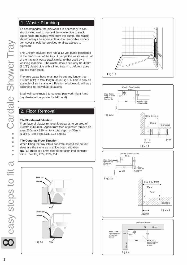
1. Waste PlumbingTo accommodate the pipework it is necessary to con-struct a stud wall to conceal the waste pipe to stack,outlet hose and supply wire from the pump. The wasteshould always be accessible and a removable inspec-tion cover should be provided to allow access topipework.
The Chiltern Invadex tray has a 12 volt pump positionedat the rear corner of the tray. It pumps the waste water outof the tray to a waste stack similar to that used by awashing machine. The waste stack need only be 40mm(1 1/2”) plastic pipe with a fitted trap in it, before it goesout into main stack.
The grey waste hose must not be cut any longer than610mm (24”) in total length, as in Fig 1.1. This is only anexample of an installation. Position of pipework will varyaccording to individual situations.
Stud wall constructed to conceal pipework (right handtray illustrated, opposite for left hand).
2. Floor Removal
1
Fig 1.1
Tile/Floorboard SituationFrom face of plaster remove floorboards to an area of660mm x 430mm. Again from face of plaster remove anarea 220mm x 220mm to a total depth of 35mm(1 3/4”). See Figs 2.1a, 2.1b and 2.3
Tile/Concrete Floor SituationWhen fitting the tray into a concrete screed the cut-outsizes are the same as in a floorboard situation.NOTE: There is a 5mm step to be taken into consider-ation. See Fig 2.2a, 2.2b, 2.4.
40
40
660
Allow 35mm deep from top of concrete screed
Wall Panel Situation
Pla
ster
430
Plaster
Allow 5mm deep from top of concrete screed
220
220
660
Allow 35mm deep from top of existing floorboards
Wooden Floor Situation
Pla
ster
430
Plaster
Remove layer of floorboards
220
220
Fig 2.1a
220mm
660 x 430mm
Fig 2.1b
Fig 2.4
35mmFloorboard
Joist
660
Allow 35mm deep from top of concrete screed
Concrete Screed Situation
Pla
ster
430
Plaster
Allow 5mm deep from top of concrete screed
220
220
Wall
660 x 430mm
30mm
5mm
concrete
Plaster
5mm tile
Tray
Plaster
10mm tile
Tray
Fig 2.2a
Fig 2.2b
Fig 2.3
220mm

8 ea
sy s
teps
to fi
t a ..
.... C
arda
le S
how
er T
ray
3. Marking the plasterPlace the shower tray into the corner and ensure thatthe shower base is level along its width and length, asFig 3.1. Mark plaster above tiling lip, as Fig 3.2 anddoor recess point.
4. Removing the plaster
6. Making good
5. Checking the level
Remove the shower tray from the wall and remove theplaster below the mark to a depth suitable to take thetiling lip, see Fig 4.1. This will vary according to thick-ness of tile to be used. Remove a small area of plasterto fit door recess point to a depth of 10mm.
2
Fig 3.2
Fig 3.1
6535 100
To length of trayTo widthof tray
60
Fig 4.1
Replace the shower tray in position. Check the flatsurface around the showering area is level (see Fig5.1). Insert packing strips if required strip of plywoodunder the tray edges to ensure water flows into pumpwell.
NOTE: The area where the doors locate must also bechecked to ensure it is level, as Fig 5.1. Fig 5.1
Drill the tiling lip at the points shown in Fig 6.1 usinga 4.5mm drill. Countersink holes, plug wall andscrew to wall using 1 1/2” no 8 slotted stainless steelscrews, not applicable for trays with panels. Securethe tray to the floor as shown in Fig 6.2, checking thetray is level before final fixing.
Insert packing strips to level if required.
Fig 6.1
Fig 6.2
6. Drilling lip
7. Before tiling Ensure that pump waste hose is connected to wasteoutlet. The pump connecting wire should also be inplace.
2. Drilling thewall
8. Fixing tray to the floor
2. Drilling thewall
3
8 ea
sy s
teps
to fi
t a ..
.... C
arda
le S
how
er T
ray
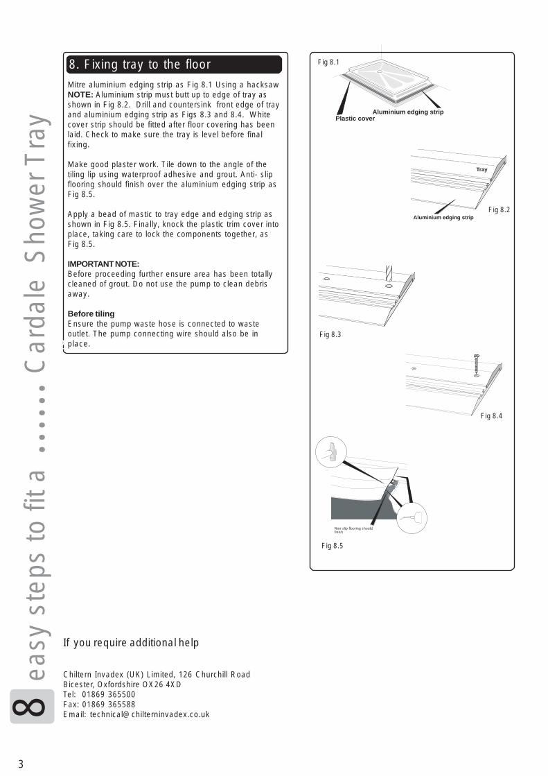
Mitre aluminium edging strip as Fig 8.1 Using a hacksawNOTE: Aluminium strip must butt up to edge of tray asshown in Fig 8.2. Drill and countersink front edge of trayand aluminium edging strip as Figs 8.3 and 8.4. Whitecover strip should be fitted after floor covering has beenlaid. Check to make sure the tray is level before finalfixing.
Make good plaster work. Tile down to the angle of thetiling lip using waterproof adhesive and grout. Anti- slipflooring should finish over the aluminium edging strip asFig 8.5.
Apply a bead of mastic to tray edge and edging strip asshown in Fig 8.5. Finally, knock the plastic trim cover intoplace, taking care to lock the components together, asFig 8.5.
IMPORTANT NOTE:Before proceeding further ensure area has been totallycleaned of grout. Do not use the pump to clean debrisaway.
Before tilingEnsure the pump waste hose is connected to wasteoutlet. The pump connecting wire should also be inplace.
Tray
Aluminium edging strip
Aluminium edging stripPlastic cover
Fig 8.5
Fig 8.1
Fig 8.3
Fig 8.2
Fig 8.4
Non slip flooring should finish
If you require additional help
Chiltern Invadex (UK) Limited, 126 Churchill RoadBicester, Oxfordshire OX26 4XDTel: 01869 365500Fax: 01869 365588Email: [email protected]
Ele
ctric
al w
orks
......
.Car
dale
pum
p an
d w
iring
blo
ck
4
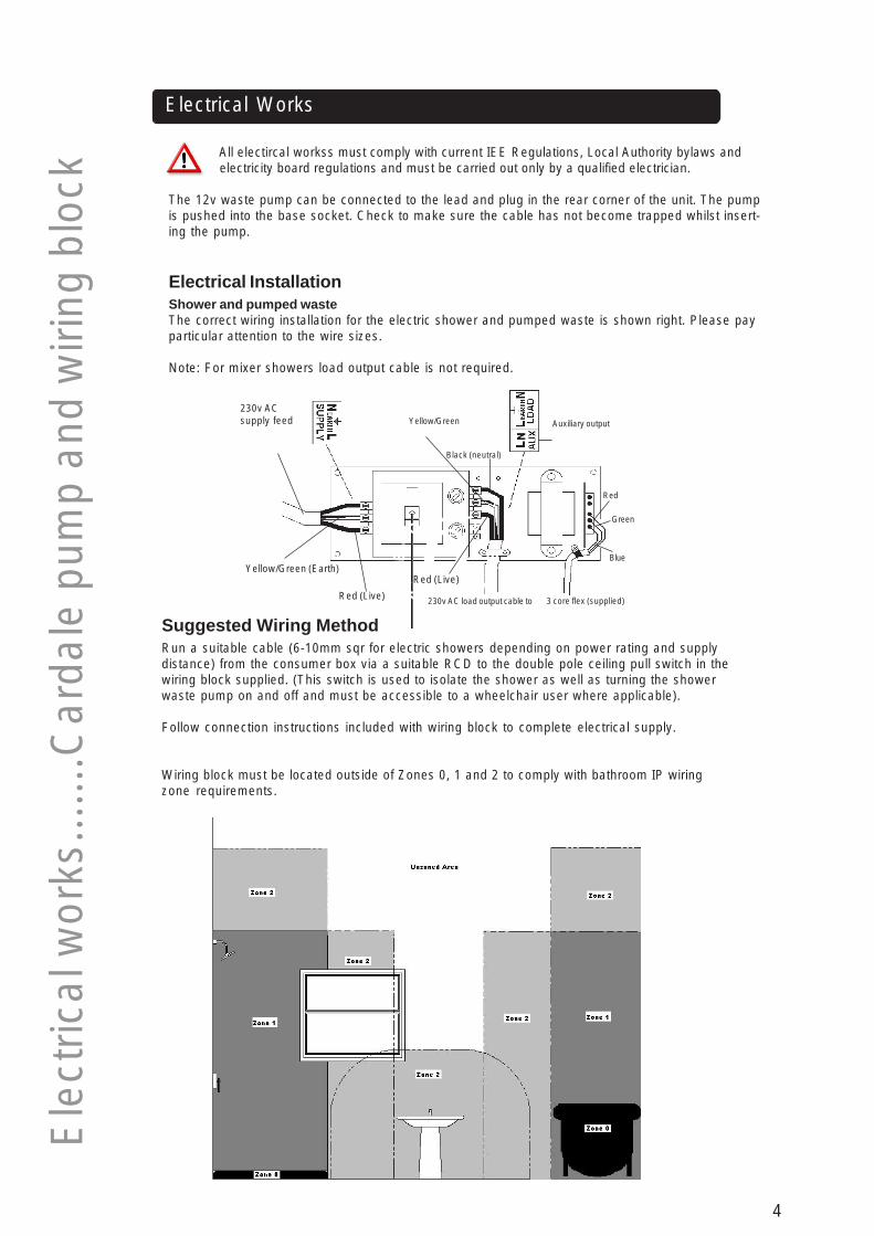
All electircal workss must comply with current IEE Regulations, Local Authority bylaws and electricity board regulations and must be carried out only by a qualified electrician.
The 12v waste pump can be connected to the lead and plug in the rear corner of the unit. The pumpis pushed into the base socket. Check to make sure the cable has not become trapped whilst insert-ing the pump.
Electrical Works
Electrical InstallationShower and pumped wasteThe correct wiring installation for the electric shower and pumped waste is shown right. Please payparticular attention to the wire sizes.
Note: For mixer showers load output cable is not required.
Suggested Wiring MethodRun a suitable cable (6-10mm sqr for electric showers depending on power rating and supplydistance) from the consumer box via a suitable RCD to the double pole ceiling pull switch in thewiring block supplied. (This switch is used to isolate the shower as well as turning the showerwaste pump on and off and must be accessible to a wheelchair user where applicable).
Follow connection instructions included with wiring block to complete electrical supply.
Wiring block must be located outside of Zones 0, 1 and 2 to comply with bathroom IP wiringzone requirements.
230v ACsupply feed
Yellow/Green (Earth)
Red (Live)
Red (Live)
230v AC load output cable to 3 core flex (supplied)
Red
Green
Blue
Auxiliary output
Black (neutral)
Yellow/Green

5
7 ea
sy s
teps
to fi
t a ..
.... C
arda
le S
how
er E
nclo
sure
50
Fig 1.3
Fig 1.4
1. Marking the wall
Place Cardale jamb with full height pole onto side oftray, as in Fig 1.1
Ensure bottom fixing plate with holes facing outwardsis in position as Fig 1.1.
Position jamb approximately 50mm from the edge, asFig 1.2 Make sure it is vertical as Fig 1.3. Mark the wallalongside the wall channel, as Fig 1.4
Fig 1.1
Fig 1.2
Fig 2.1
Fig 2.3
Fig 2.2
2. Drilling the wall
Remove channel from jamb and place on wall as Fig2.1. Using a pencil mark through the slots and drill thewall 50mm deep (2”) using a 5.5mm drill, as Fig 2.2 &2.3. Apply a film of silicone sealant to the inside edge ofthe wall channel.
Secure to wall with wall plugs and 1 1/2” x No 8 screws.
Push panel into wall channel. Fasten loosely with selftapping screws, slot covers and shakeproof washersprovided. Repeat with pole section ensuring fixingplate is in position. Check panel is level horizontallyand vertically. Screws are fully tightened later. Thepole fixing plate is also screwed in position later.
3. Fixing the jamb panel
Fig 3.2
Fig 3.1
6
7 ea
sy s
teps
to fi
t a ..
.... C
arda
le S
how
er E
nclo
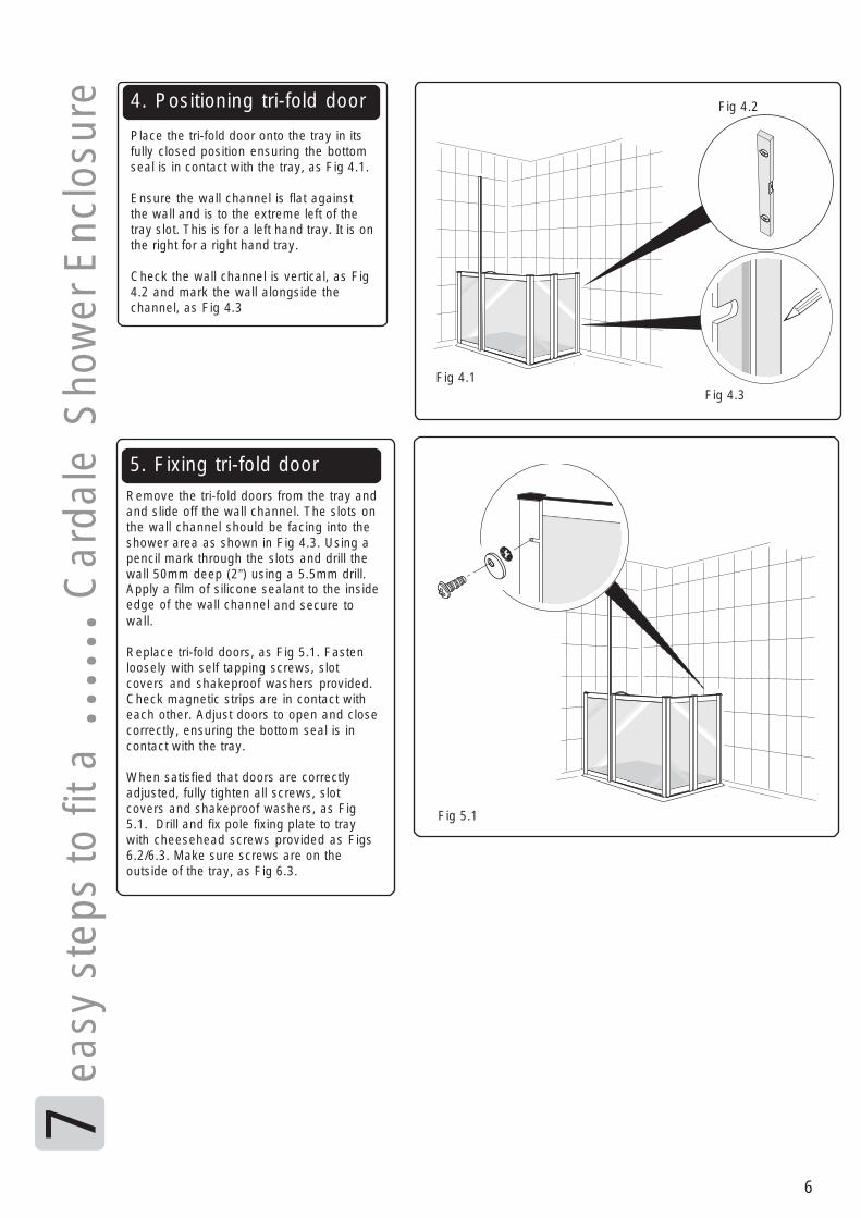
sure 4. Positioning tri-fold door
Place the tri-fold door onto the tray in itsfully closed position ensuring the bottomseal is in contact with the tray, as Fig 4.1.
Ensure the wall channel is flat againstthe wall and is to the extreme left of thetray slot. This is for a left hand tray. It is onthe right for a right hand tray.
Check the wall channel is vertical, as Fig4.2 and mark the wall alongside thechannel, as Fig 4.3
Fig 4.2
Fig 4.1Fig 4.3
5. Fixing tri-fold doorRemove the tri-fold doors from the tray andand slide off the wall channel. The slots onthe wall channel should be facing into theshower area as shown in Fig 4.3. Using apencil mark through the slots and drill thewall 50mm deep (2”) using a 5.5mm drill.Apply a film of silicone sealant to the insideedge of the wall channel and secure towall.
Replace tri-fold doors, as Fig 5.1. Fastenloosely with self tapping screws, slotcovers and shakeproof washers provided.Check magnetic strips are in contact witheach other. Adjust doors to open and closecorrectly, ensuring the bottom seal is incontact with the tray.
When satisfied that doors are correctlyadjusted, fully tighten all screws, slotcovers and shakeproof washers, as Fig5.1. Drill and fix pole fixing plate to traywith cheesehead screws provided as Figs6.2/6.3. Make sure screws are on theoutside of the tray, as Fig 6.3.
Fig 5.1

7
7 ea
sy s
teps
to fi
t a ..
.... C
arda
le S
how
er E
nclo
sure 6. Fitting the end caps
Fit end caps as shown in Fig 6.1. Note:On final fixing black end caps need to besecured in position using siliconesealant. Fit pole cover strips, as Fig 6.4.
Fig 6.3
Fig 6.1
Fig 6.2
Fig 6.1Fig 6.4
7. Fitting curtain rail and shower curtain
Position curtain rail at height to connect to bracket at top of grab pole. Check level & mark walls for fixing wallbrackets, as Fig 7.1. Drill wall with 5.5mm drill to a depth of 2” (50mm). Fix curtain rail brackets to wall withplugs and 1 1/2” x No 8 screws, as Fig 7.2. Load hooks and glides into bottom channel of curtain rail. Place 1M5 nut in top channel of curtain rail as Fig 8.1. Attach to brackets and tighten with the allen key provided, asFig 7.3.
Check pole is vertical. Using M5 X 10mm stainless steel screw attach to curtain rail with nut already in place,as Fig 8.1. Using 3/4” x 6’s stainless steel screws secure pole bracket to top of pole rail, as Fig 8.2. Attachshower curtain to hooks on rail, as Fig 7.4.
Fig 8.2Fig 8.1
Fig 7.1 Fig 7.2
Fig 7.4
Fig 7.3
If you require additional help
Chiltern Invadex (UK) Limited, 126 Churchill RoadBicester, Oxfordshire OX26 4XDTel: 01869 365500Fax: 01869 365588Email: [email protected]

8
User Instruction
The pump is controlled by the wiring block and pull cord which should be installed by an
electrician in a safe area.
To operate the pump
Pull cord prior to entering shower to provide power to the pump.
To turn the pump off
After showering wait for approx 1 minute to allow the residual water to be pulled from the sump
and then pull cord to disable pump.
Trouble Shooting
Waste hose is blocked.
Water left in sump at backof shower after use.
Stagnant soapy water inthe back gully.
float switch alarmtriggered
Loss of power to pumpunit
Blockage in waste pipe oroverflow
Alarm triggered
Unblock waste hose. Run pump aftershowering for 1 minute to clear excess water.
This is normal. The water left in the waste hosewhen the pump stops will run back when the pumpstops.
The shower should be run for a couple of minutesafter use to ensure that the residual water is clean.
Ensure float switch is moving freely and is notstuck or jammed
Broken re wire kit lead/fault with pcb unit withinpower supply(electrician/service engineer required to assess)
Check for blockage within waste outlet hose orplastic overflow pipe
Check there is no break in the solder connection tothe power supply (connection under rubber boot)Electrician/service call required)
symptom suggested cause solution
Pumped shower wastewater level is higher thannormal.
There is an unpleasantodour.
Beeping from powerSupply
No function from wastepump
Water flooding back intotray through pump
Continual Beeping frompower supply

9
Cleaning and Maintenance
The Shower Waste Pump does not require any major maintenance, but should be regularlycleaned to prevent damage.
Pump MaintenanceRegularly (monthly) lift pump from the socket in the base and remove foreign matter fromthe blades. Scrub the area around the pump with a long handled stiff brush. This will reducethe build up of scum and odours.
Check that the small bore hole adjacent to the pump blades is clean(as shown below below)
Tray and Enclosure Maintenance
To retain the surface quality of your shower tray and enclosure clean using bathroom clean-ing mousse or washing-up liquid, warm water and a soft cloth is recommended. Do notscouring powder or abrasive pads which may spoil the surface appearance.
Cross infection
If this unit is to be utilised by many different bathers, then we would strongly recommend thatthis unit be cleaned with a medical disinfectant. Please contact your local infection control nursefor further advice.

10
Spare Parts Guide
Item No. Description Part No.1 Pole Set including fixing pack - Left Hand - White IDACP01W2 Pole Set including fixing pack - Right Hand - White IDACP02W3 Left Hand Jamb - White IDACJ01W4 Right Hand Jamb - White IDACJ02W5 Right Hand Tri-fold Door - Cardale IDACTD01W6 Left Hand Tri-fold Door - Cardale IDACTD02W7 Left Hand Alcove Door (handed from point of hinge) IDACA01W8 Right Hand Alcove Door (handed from point of hinge) IDACA02W9 Left Hand Shower tray* IDIC0510 Right Hand Shower tray* IDIC0711 Cardale Pump Cover - White SH0695W12 Wiring block SHSU05013 Curtain rail L shaped (1295 x 735mm) IDGRL5129WNot shown Straight curtain rail (1840mm) IDGRS72W14 Curtain (2200mm width x 1750mm length) IDGSS22Not shown Curtain (for straight curtain rail) 1800 W x 1800mm L IDGSS01Not shown Waste Outlet hose - Grey SHSU019Not shown 12V Waste Pump (plus 90 degree float switch) SHPU032-HNot shown Re-wire kit (plus plug) 12V SHPU004/12
3
1
9
5
2
4
10
11 11
6
7 8
Hinge Hinge
12
1313 1313
11
WarrantyYour Chiltern Invadex Shower Enclosure, pump and wiring block carry a 12 monthwarranty from the date of purchase (for guarantee on shower unit see manufacturersdetails), subject to the following:-
1. Should you experience any problems with our workmanship ormaterials within the first 12 months period, please contact your pointof purchase.
2. Repairs made during the warranty period will be carried out free ofcharge, provided the product has been used strictly in accordancewith the guidelines set out in this user guide.
3. Our warranty does not cover replacements, adjustments or repairswhich may be required as result of normal wear and tear, wilful oraccidental damage, misuse, neglect or any other cause which isbeyond the control of Chiltern Invadex.
4. Modifications and repairs made to this product by unauthorisedpersons will render the warranty void.
5. Only parts manufactured or approved by Chiltern Invadex shall beused to repair this product. Use of unauthorised parts will invalidateall warranties and remove all liability from Chiltern Invadex for thesafety of this product.
6. Chiltern Invadex shall in no event be liable for any damages, costs orexpenses arising from any claim made under this warranty (save forany legal liability of Chiltern Invadex for death or personal injuryresulting from the company’s negligence in respect of its products).
7. Faults due to inadequate cleaning, limescale or other water impuritiesincluding debris not flushed from the supply pipe work prior toconnection are excluded from this warranty.
8. This warranty does not affect your statutory consumer rights.
The Shower Tray has a 25 year manufacturing fault warranty.


Copyright © Chiltern Invadex (UK) Ltd. The design of the product shown in this installation guide is vested in Chiltern Invadex (UK) Ltd and should not be copied orreproduced in anyway whatsoever without the express permission in writing of Chiltern Invadex (UK) Ltd. This is an original design of Chiltern Invadex (UK) Ltd in whichDesign Right subsists.Published by Chiltern Invadex (UK) Ltd 126 Churchill Road Bicester Oxon OX26 4XD Registered in England No: 04704248 CINV 155.05 May 2012
Leve
l Acc
ess
Sho
wer
sC
arda
leChiltern Invadex (UK) Limited
126 Churchill RoadBicester
OxfordshireOX26 4XD
Tel: 01869 365500Fax: 01869 365588
Email: [email protected]
.
The crossed wheelie bin symbol shown on this product indicates that the item must not be disposed of with general household waste. Proper recovery of your waste electronic and electrical equipment will ensure safety of human health and the environment.
For more information where the product can be safely disposed of please contact your Local Authority, the dealer from where the product was purchased or Chiltern Invadex (UK) Limited.
WEEE producer number WEE/JD1274RU