Carbon Trust Offshore Wind Accelerator roadmap … roadmap for the commercial acceptance of floating...
30
Transcript of Carbon Trust Offshore Wind Accelerator roadmap … roadmap for the commercial acceptance of floating...

OWA roadmap for the commercial acceptance of floating LIDAR technology
2
Foreword Floating LIDAR has the potential to replace meteorological met masts for the measurement of primary wind resource data – wind speed and wind direction. The purpose of this document is to present a roadmap for floating LIDARs to become commercially accepted as a source of data to support financial investment decisions. The roadmap has been prepared by the Carbon Trust Offshore Wind Accelerator (OWA), a joint industry project involving nine developers representing over three-quarters of the UK’s licenced capacity – DONG Energy, E.ON, Mainstream Renewable Power, RWE Innogy, ScottishPower Renewables, SSE Renewables, Statkraft, Statoil and Vattenfall – in close collaboration with Garrad Hassan & Partners Ltd as lead authors, and with input from DNV KEMA, Mott MacDonald, ECN and Frazer Nash Consultancy. The developers in the OWA are of the opinion that the accuracy of floating LIDAR systems should be evaluated in comparison to an IEC compliant meteorological mast by an independent third party according to the guidelines set out in this document. In order to support floating LIDAR suppliers to achieve this, the OWA will facilitate trials of floating LIDAR systems compared to meteorological masts within their portfolio of projects.

OWA roadmap for the commercial acceptance of floating LIDAR technology
3
Important notice and disclaimer
This report is issued by the Carbon Trust on behalf of the Offshore Wind Accelerator (“OWA”). While reasonable steps have been taken to ensure that the information contained within this report is accurate, the authors, the Carbon Trust, its agents and consultants and the partners and developers within the OWA (and each of them), to the fullest extent permitted by law, shall not have nor be deemed to have (1) a duty of care to readers and/or users of this report, (2) made or given or to make or give any warranty or representation (in each case whether express or implied) as to its accuracy, applicability or completeness and/or (3) or have accepted any liability whatsoever for any errors or omissions (whether negligent or otherwise) within it. It should also be noted that this report has been produced from information relating to dates and periods referred to in it. Users and readers use this report on the basis that they do so at their own risk. The intellectual property rights in this report shall be deemed, as between readers and users of this report and the Carbon Trust, to belong to the Carbon Trust
Published in the UK: November 2013
© The Carbon Trust
OWA roadmap for the commercial acceptance of floating LIDAR technology
4
Contents
Foreword 2
Contents 4
List of tables and abbreviations 5
Acknowledgements 6
1 Introduction 7
1.1 Background 7 1.2 Cautionary note 7
2 Stages of maturity 8
2.1 Summary 9 Table 2.1: Summary of FLD scenarios examined 9 2.2 Stage 1: Baseline 11
2.2.1 Definition 11 2.2.2 Prerequisites 11 2.2.3 Offshore application 12 2.2.4 Limitations of offshore application 12 2.2.5 Expected levels of measurement uncertainty 12
2.3 Stage 2: Pre-commercial 13 2.3.1 Definition 13 2.3.2 Prerequisites 13 2.3.3 Offshore application 14 2.3.4 Limitations of offshore application 14 2.3.5 Expected levels of measurement uncertainty 16
2.4 Stage 3: Commercial stage 17 2.4.1 Definition 17 2.4.2 Prerequisite 17 2.4.3 Offshore application 18 2.4.4 Limitations of offshore application 18 2.4.5 Expected levels of measurement uncertainty 18
2.5 Other considerations 19
3 Conclusions 20
Appendix 1 22
Suggested acceptance criteria for pilot validation trial 22
OWA roadmap for the commercial acceptance of floating LIDAR technology
5
List of tables
Table 2.1: Summary of FLD scenarios examined 9
Table 2.2 Summary of Roadmap 10
List of abbreviations
Abbreviation Meaning CNR Carrier-to-Noise Ratio FLD Floating LIDAR Device GL GH GL Garrad Hassan
KPI Key Performance Indicator NaN Not a Number (IEEE symbol) OWA Offshore Wind Accelerator QA Quality Assurance QC Quality Control

OWA roadmap for the commercial acceptance of floating LIDAR technology
6
Acknowledgements
The Carbon Trust would like to thank the following companies for their contribution to this report
Garrad Hassan & Partners Ltd
DONG Energy, E.ON, Mainstream Renewable Power, RWE Innogy, ScottishPower Renewables, SSE Renewables, Statkraft, Statoil, Vattenfall
Frazer Nash Consultancy
DNV KEMA, Mott MacDonald, ECN
The Carbon Trust would like to acknowledge prior research into the development of LIDAR for offshore applications1
1. Papers including
Oldroyd, A; Kindler D: Wind Measurements using floating LiDAR Best Practice June 2011
A Framework for Best Practice Use of Floating LiDAR Systems, 17th April Poster Session, PO. 549@ European Wind Energy Association (EWEA) 2012 – Copenhagen, A. Oldroyd, D. Kindler

OWA roadmap for the commercial acceptance of floating LIDAR technology
7
1 Introduction
1.1 Background
As part of the Offshore Wind Accelerator programme, The Carbon Trust, along with a consortium of industrial partners, are investigating the potential of floating LIDAR technology in the context of wind resource assessment for the offshore wind industry. The Carbon Trust Offshore Wind Accelerator (OWA) has developed this guide or “roadmap” for the steps required for this immature technology to become commercially accepted within the industry, as reported in this document. The report has been prepared in close collaboration with GL Garrad Hassan.
In this context, "commercial acceptance" is defined as the stage at which measurement data recorded using a particular floating LIDAR technology is accepted by funders of commercial scale offshore wind projects. In broad terms, the following stages are envisaged:
1. Baseline: As a pre-requisite, the LIDAR measurement unit itself should have achieved wide-spread acceptance within the onshore wind industry as "proven" in the field of wind resource characterisation for non-complex terrain sites at least.
2. Pre-commercial: Following a successful pilot validation trial, the floating LIDAR technology may be utilised commercially in limited circumstances - specifically in conditions similar to those experienced during the trial. Elevated measurement uncertainty assumptions may be expected for such application, when benchmarked against the deployment of a conventional fixed offshore meteorological mast.
3. Commercial: Following successful further trials and early commercial deployments covering a range of site conditions, a sufficient body of evidence is accumulated to relax the elevated uncertainty assumptions.
In this roadmap document, the above stages are described qualitatively in greater detail in Section 2. Finally, conclusions and recommendations are drawn regarding the guidance provided and the application of floating LIDARs to future deployment of this technology at the pre-commercial and commercial stages.
1.2 Cautionary note
It is important to note that this roadmap was designed to focus on the capabilities of floating LIDAR technology to replace met masts in measuring primary wind data, namely wind speed and wind direction. There are other secondary but important parameters required for a comprehensive offshore wind resource assessment such as hub-height turbulence intensity,
OWA roadmap for the commercial acceptance of floating LIDAR technology
8
temperature, air density, relative humidity etc. Additionally, complementary oceanographic measurements are also required to achieve a full met-ocean measurement campaign. Therefore, while some floating LIDARs currently feature additional measurement capabilities and while future developments might add even more comprehensive measurement capabilities, it is important to bear in mind that this document is only a roadmap towards replacing primary wind data measured from offshore met masts with floating LIDARs, and that secondary wind data and met-ocean measurements will still need to be taken to complete a comprehensive offshore wind resource and met-ocean measurement campaign.
Additionally, although system availability is one of the KPIs used in this roadmap, this document does not directly address or cover the seaworthiness of the floating LIDAR devices.
2 Stages of maturity
Floating LIDAR Devices (FLDs) are based on laser anemometry known as LIDAR (Light Detection and Ranging) technology which has been developed for various industries, including the wind energy industry. In addition to a body of onshore validation data for the LIDAR unit itself, it is also important that the performance of the complete FLD is rigorously validated within the offshore environment to demonstrate that it can operate effectively across a range of dynamic conditions.
There are potentially significant issues requiring careful consideration regarding the accuracy of the measurements when the device is deployed on a moving support structure. From an engineering perspective, there appear to be two main approaches to address these issues. The first is to minimise the movement of the support structure such that all, or at least the majority, of the measurements are made when the amplitude of device movement is sufficiently small so that the impact on the accuracy of the measurements may be negligible. The second approach is to measure that movement and correct for its impact on the measurements using numerical algorithms.
The use of FLDs in place of or in combination with conventional offshore meteorological masts offers potential benefits for the industry in terms of development costs, consenting timescales and the uncertainty associated with wind resource estimates. However, a significant body of supporting validation data must be established for each FLD to enable the confidence to be gained in measurement accuracy and reliability to move through the 3 stages of maturity defined in this roadmap document; Baseline, Pre-commercial and Commercial. The following subsections provide definitions, application limitations and milestones for each of these stages.

OWA roadmap for the commercial acceptance of floating LIDAR technology
9
2.1 Summary
The prerequisites, possible modes of application, requirements for and limitations of deployment for each maturity stage are summarised on the following page, including an indicative assessment of the measurement accuracy that would be expected in each case. This roadmap diagram in Table 2.2 serves as a summary guide to the remainder of this section, which provides the detailed rationale. Indicative scenarios of plausible FLD deployment used in the diagram are summarised below in
Table 2.1.
Table 2.1: Summary of FLD scenarios examined
Deployment Type Maturity Stage
Baseline Pre-commercial Commercial
One FLD unit replacing a met mast N / A Scenario B Scenario E
Multiple FLD units replacing a met mast1 N / A Scenario C Scenario F
Fixed met mast supplemented by one or more floating LIDAR
Scenario A Scenario D Scenario G
1 For multiple FLD scenarios it is assumed that identical FLD types/models are utilised.
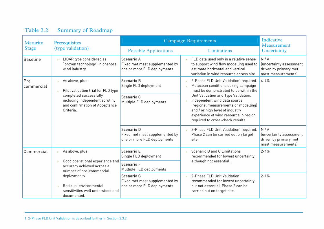
Table 2.2 Summary of Roadmap
Maturity Stage
Prerequisites (type validation)
Campaign Requirements Indicative Measurement Uncertainty Possible Applications Limitations
Baseline > LIDAR type considered as “proven technology” in onshore wind industry.
Scenario A Fixed met mast supplemented by one or more FLD deployments
> FLD data used only in a relative sense to support wind flow modelling used to estimate horizontal and vertical variation in wind resource across site.
N / A (uncertainty assessment driven by primary met mast measurements)
Pre-commercial
> As above, plus: > Pilot validation trial for FLD type
completed successfully including independent scrutiny and confirmation of Acceptance Criteria.
Scenario B Single FLD deployment
> 2-Phase FLD Unit Validation1 required. > Metocean conditions during campaign
must be demonstrated to be within the Unit Validation and Type Validation.
> Independent wind data source (regional measurements or modelling) and / or high level of industry experience of wind resource in region required to cross-check results.
4-7%
Scenario C Multiple FLD deployments
Scenario D Fixed met mast supplemented by one or more FLD deployments
> 2-Phase FLD Unit Validation1 required. Phase 2 can be carried out on target site.
N / A (uncertainty assessment driven by primary met mast measurements)
Commercial > As above, plus: > Good operational experience and
accuracy achieved across a number of pre-commercial deployments.
> Residual environmental
sensitivities well understood and documented.
Scenario E Single FLD deployment
> Scenario B and C Limitations recommended for lowest uncertainty, although not essential.
2-4%
Scenario F Multiple FLD deployments
Scenario G Fixed met mast supplemented by one or more FLD deployments
> 2-Phase FLD Unit Validation1 recommended for lowest uncertainty, but not essential. Phase 2 can be carried out on target site.
2-4%
1. 2-Phase FLD Unit Validation is described further in Section 2.3.2.
OWA roadmap for the commercial acceptance of floating LIDAR technology
11
2.2 Stage 1: Baseline
2.2.1 Definition
At this stage, operational devices are available and some preliminary demonstration tests have been carried out or are in progress. An FLD is considered to be within the Baseline stage as long as no independent and thorough offshore validation test as defined in Section 2.2.2, has been successfully completed.
2.2.2 Prerequisites
As a pre-requisite, the LIDAR product used in the FLD – including its hardware and firmware – should have achieved wide-spread acceptance within the onshore wind industry as "proven technology" in the field of wind resource characterisation for non-complex terrain sites. Currently, not all LIDAR types are considered as proven technology while a few have indeed reached this stage and therefore individual units of the LIDAR product in question can be deployed for wind resource measurement with a reasonable level of confidence.
To be considered as proven technology for onshore applications, the LIDAR must be commercially available and be capable of routinely providing measurements of wind speed and direction with height. More precisely, multiple independent reports should be available supporting its successful validation against high-quality mechanical anemometry in simple terrain/flow under various atmospheric conditions and at measurement heights relevant to modern wind turbines.
A milestone is reached when one or more production units have been successfully tested at one or more suitable and recognized test facility(ies) against data recorded from a high-quality conventional wind measurement met mast over a range of heights, operational, atmospheric and simple flow/terrain conditions relevant to wind energy applications. The tests will have demonstrated that the accuracy achieved through remote sensing is similar to that which would have been achieved with conventional anemometry for measuring 10-minute average wind speed and wind direction. The results of the test must be published in a suitable technical paper.
Once the above-mentioned milestone is reached, the LIDAR type gains wide use and an increasing number of production units are deployed on a range of sites with different meteorological characteristics. Additionally, more operational experience is gained and more is learned about the set-up, robustness and consistency of the measurement equipment when comparing various units. Confidence is gained that LIDAR units provide robust, continuous and accurate data over the full spectrum of operational conditions. Alternatively specific conditions where the LIDAR type and its individual units do not provide
OWA roadmap for the commercial acceptance of floating LIDAR technology
12
robust data become well understood and can be excluded from analyses. Data from individual units of the LIDAR type may be used quantitatively within an onshore formal wind speed and energy assessment in non-complex terrain/flow although, in some instances, site-specific validations for a given unit against conventional anemometry data may be required. At this stage, the LIDAR type is considered as proven technology and it is common that in onshore non-complex terrain and flow, the error bars associated with measurements provided by individual LIDAR units are similar to those of high-quality mechanical anemometry.
2.2.3 Offshore application
Data from FLD at this stage are not deemed reliable enough to be used quantitatively in the context of a formal wind resource assessment. However, it is expected that they can provide qualitative information to supplement fixed offshore wind measurement sensors and these circumstances are assessed quantitatively under Scenario A (Section 3).
2.2.4 Limitations of offshore application
There are no formal requirements for FLD at this stage as they are not expected to provide acceptably validated wind data. However, it is recommended that metocean conditions be measured and documented to help build a body of knowledge on the performance of the technology and its sensitivity to external and operational parameters.
2.2.5 Expected levels of measurement uncertainty
At this stage, the FLD data shall only be utilised in a relative sense, to support wind flow modelling and potentially other sources used to estimate horizontal and vertical variation in wind resource across site. Absolute wind resource estimates will be anchored to analysis of the fixed met mast data and therefore uncertainty levels shall be primarily driven by this primary source.
OWA roadmap for the commercial acceptance of floating LIDAR technology
13
2.3 Stage 2: Pre-commercial
2.3.1 Definition
At this stage, FLD units are commercially available, have fulfilled the Baseline stage requirements and, an independent third-party has published a Type Validation document for the technology (as described below). However, a sufficient body of knowledge may not be available to relax potentially elevated measurement uncertainty estimates. Moreover, operational requirements and limitations are insufficiently studied and documented so that there is a significant level of uncertainty as per their performance on any given offshore site, especially where the expected environmental conditions differ significantly from those experienced during the pilot validation trail(s).
2.3.2 Prerequisites
For a floating LIDAR technology at Baseline stage, a milestone is reached when at least one unit has successfully completed at least one pilot validation trial. The FLD is then said to have achieved Type Validation. For the pilot validation trial, a 2-phase protocol as described below is required.
The 2-phase protocol is designed to:
> Validate the LIDAR performance onshore in a fixed frame of reference and in the absence of any motion; and,
> To validate the floating LIDAR performance offshore under dynamic conditions and under wind and sea conditions representative of its future deployment locations.
The onshore validation of the unit should be performed against high-quality conventional anemometry. Indeed, at this preliminary stage, it is considered that despite the fact that the LIDAR unit belongs to a proven LIDAR type; the specific performance of the unit at hand should be precisely determined before any offshore test is undertaken.
The offshore validation would need to be undertaken at an actual offshore site against a reliable and traceable fixed offshore meteorological mast designed in accordance with relevant industry standards and best practice. The offshore validation test is to determine the accuracy achieved by the FLD as referenced against to that achieved with fixed cup-anemometry already accepted for formal wind resource and energy yield assessments. Metocean conditions should be documented and relevant sensitivity analyses should be undertaken to show the extent to which external parameters and conditions affect remote sensing device performance. The exact methodology for the trail should be considered on a case by case basis. However, suggested Acceptance Criteria have been developed by the Carbon Trust and the OWA industrial partners in collaboration with GLGH, and these are
OWA roadmap for the commercial acceptance of floating LIDAR technology
14
reproduced in Appendix 1. It is noted that independent scrutiny of trial design and execution is recommended and that the performance of FLD units over the trial be clearly validated against “minimum” and “best practice” Acceptance Criteria.
It is noted that in some circumstances detailed turbulence and gust information may be a formal requirement of certification bodies or turbine manufacturers and therefore careful consideration should be given to this point in the specification of a measurement campaign. Turbulence Intensity (TI) is also of relevance for wake modelling when assessing Annual Energy Production (AEP). It is noted that for TI in particular, it is recommended that the data available from the FLD demonstrate that turbulence data are sufficiently accurate, or alternatively, they can be complemented or corrected, notably by using an on-site independent source of data, to provide the inputs required for site feasibility assessment, structural design and wake modelling purposes.
The results of the Type Validation test must be published in a suitable technical paper to serve as a reference document for the FLD technology.
2.3.3 Offshore application
Once the above-mentioned milestone is reached and the FLD is considered to have achieved Type Validation, it is expected that it could be deployed on offshore sites to supplement fixed offshore wind sensors (Scenario D) or as a stand-alone source of wind data (Scenarios B and C) provided the requirements of the next subsection are met.
2.3.4 Limitations of offshore application
2-phase validation of each unit
During this stage, FLD units to be deployed for offshore wind resource assessment are to follow the 2-phase validation protocol (see Section 2.3.2) before the actual measurement campaign may begin. The purpose of the preliminary 2-phase validation is twofold:
> To avoid tracing back the performance of all units to a single test, namely the Type Validation trial results; and,
> To gain confidence that different units provide consistent, robust, continuous and accurate data over a variety of operational, atmospheric and sea conditions.
Metocean conditions are to be accurately measured and documented during the 2-phase validation protocol to help understand FLD performance during the tests and later during the actual offshore measurement campaign.

OWA roadmap for the commercial acceptance of floating LIDAR technology
15
If the outcome of the 2-phase validation protocol is not consistent with previous such tests, notably those of the Type Validation (pilot) trial, the FLD unit may not be suitable for use in the context of a formal uncertainty analysis. In such circumstances, the causes of unexpected performance should be investigated and explained.
Metocean conditions
For stand-alone applications (Scenarios B and C), it is required that the metocean conditions which have prevailed during the 2-phase validation described above be representative of those expected on site during the measurement campaign. More precisely, it is expected that the external and operational parameters which are deemed to affect the FLD performance do not exceed significantly the ranges observed during the 2-phase validation trial. Alternatively, it must be demonstrated that either the impacts are negligible or that they can be reliably quantified based on data from available information, literature or acceptable data analyses.
A preliminary list of parameters which may affect the performance of the FLD is provided below.
> Wind speed > Wind direction > Vertical gradient of wind speed ( wind shear) > Turbulence Intensity > Flow angle > Wind veer > Pitch, Roll and Yaw > Motion compensation activity > Angular speeds and or accelerations > Wave height > Wave period > Wave steepness > Current magnitude > Wind-wave misalignment > Air temperature > Air differential temperature > Water temperature > Water-air differential temperature > Rain, precipitation > Cloud height > Visibility, fog, mist
Some of the parameters listed above may be correlated and therefore their impact on the performance of the FLD may be indirect. Moreover, some parameters (e.g. pitch and roll
OWA roadmap for the commercial acceptance of floating LIDAR technology
16
angles) may have a more significant impact. Additional field data is required to perform sensitivity analyses of the statistics of the FLD errors as a function of the listed parameters to drive conclusions. Therefore, defining the representativeness of a given set of parameters may not be a trivial task at this point in time with the available body of knowledge.
As a first approximation, validation test conditions may be deemed representative of site conditions if the magnitudes of parameters listed above during the measurement campaign remain within the ranges observed during the validation tests. Recorded wind data during periods where such tertiary parameters fall outside of the validation envelope should be considered with care, and potentially rejected.
Independent source of site wind data
During the Pre-commercial Stage, it is important to monitor the consistency of the performance of the FLD during the measurement campaign. It is therefore required that an independent and reliable source of site wind data be available to perform periodic and regular sanity checks. The presence of such an independent source of wind data would also serve to mitigate risks associated with a lack of redundancy, risks of systematic errors and other issues such as those related to measuring on-site Turbulence Intensity (TI) with a LIDAR – provided the said source of wind data does indeed provide this information.
In case a stand-alone application is sought (Scenarios B and C), it is required that a good level of regional wind climatology knowledge be available. Such a body of knowledge may be based on previous studies and modelling or come from nearby reliable sources of fixed wind data sources.
Post-campaign validation
Should inconsistencies in LIDAR performance be observed during the measurement campaign, an onshore post-validation conducted in the same way as the pre-campaign validation, is required to help determine the root cause of the problem and potentially salvage the measurement campaign.
2.3.5 Expected levels of measurement uncertainty
At this stage, somewhat elevated levels of uncertainty can be expected for wind data gathered during a FLD campaign when compared to those from a conventional fixed offshore met mast campaign. This reflects the lack of a substantial body of validation evidence and the potential operation of the systems in conditions outside of the validation envelope. Metocean conditions are to be precisely defined during the actual offshore measurement campaign to allow uncertainty analyses and to help understand FLD performance. Possible

OWA roadmap for the commercial acceptance of floating LIDAR technology
17
instances where elevated uncertainties could be lowered to some extent include, but are not limited to, the following:
> 2-Phase validation protocol results indicate low levels of LIDAR error that is meeting “best practice” Acceptance Criteria as defined in Appendix 1.
> Metocean conditions during measurement campaign are similar and within the range of those which prevailed during the 2-phase validation protocol.
> No inconsistent performance was observed or detected during the measurement campaign, for example the observation of systematic shifts in wind speed ratios over time for specific wind direction sectors, when cross-correlating to fixed validation data sources.
> An onsite independent and reliable source of wind data, be it based on modelling or measurements, is available to check or complement LIDAR data.
At the end of the measurement campaign, if for any reason the error bars for FLD data cannot be reduced sufficiently despite available data, information and analyses, it is expected that the FLD data could only be used to inform a central estimate of wind resource on the site in question and a formal energy uncertainty assessment should not be undertaken.
2.4 Stage 3: Commercial stage
2.4.1 Definition
The LIDAR type is considered to have achieved commercial acceptance with respect to formal wind resource and energy yield assessment reports, incorporating uncertainty analyses and quantification of confidence limits in terms of energy yield expectations at various levels of probability such as 90% (P90), 95% (P95) and 99% (P99) commonly used for project financing. Wind data from FLDs at this stage may be used quantitatively with only limited or even in the absence of site-specific validation. Expected error bars should be comparable to those assigned to conventional offshore met masts provided best practice are followed and robust data quality control and uncertainty analyses have been undertaken and documented.
2.4.2 Prerequisite
At this stage, FLD units are commercially available, have fulfilled the Pre-commercial stage requirements and, following successful further trials and early commercial deployments covering a range of operational, site and metocean conditions, a sufficient body of evidence through independent third-party reports is accumulated to relax the elevated uncertainty assumptions. In particular specific conditions where the technology does not provide robust data become well understood so that they can be excluded from analyses.

OWA roadmap for the commercial acceptance of floating LIDAR technology
18
2.4.3 Offshore application
It is expected that at this stage, FLD data can be used quantitatively to supplement data from conventional offshore mast cup anemometry (Scenario G) or as a stand-alone data source (Scenarios E and F) provided the requirements below are met. For stand-alone applications, as previously mentioned, attention should be paid to such concerns as redundancy, performance consistency, potential systematic errors and TI measurement.
2.4.4 Limitations of offshore application
It is expected that for the FLD technology to become a mature and widely accepted means of offshore wind resource assessment, a set of best practice and QA/QC rules will be needed to ensure a consistent and high level of quality. As a general rule, the following recommendations are seen as best practice rules which would bring additional confidence in the reliability and accuracy of the FLD data:
> FLD sanity or consistency checks using an independent source of wind data during the campaign.
> 2-phase validation trial before an offshore wind resource campaign begins. Alternatively, a single-phase (offshore) validation trial may be appropriate.
> Additional confidence in the reliability and accuracy of the FLD when operated within metocean ranges where its performance has been proved.
Should an inconsistent performance be observed during a measurement campaign, an onshore post-validation is required to determine the cause, explain the observations and, if possible, attempt to salvage the measurement campaign in case a serious anomalous behaviour is detected.
2.4.5 Expected levels of measurement uncertainty
It is expected that following the recommendations presented in the previous subsection, an increased level of confidence would be gained in the results and the related uncertainty levels of FLD wind data. It is expected that under ideal conditions, and notably during calm sea periods, FLD measurement uncertainty could be as low as those of high-quality and well mounted cup anemometers on high quality hub height meteorological masts. However, the actual uncertainty levels will be site-specific and would eventually need to be evaluated based on available information and data and by following industry standards.

OWA roadmap for the commercial acceptance of floating LIDAR technology
19
2.5 Other considerations
Regardless of the level of maturity or acceptance of the technology, the length of the data set and achieved data coverage rates at hub height are key considerations in measurement campaigns. Remote sensing campaigns should span a similar period as those undertaken with conventional masts and both should also take account of the availability of suitable long-term reference data for use in Measure-Correlate-Predict type analyses. In particular, care should be given to circumstances, if any, where specific operational or metocean conditions may reduce data availability or reliability and therefore result in systematic errors or uncertainties. Also, it is important to deploy a device with a sufficient power supply and an appropriate O&M program such that it can be expected that data coverage rates up to hub height will be high (see appendix for availability KPIs). In addition, it is important that the equipment and power supply are such that the FLD may operate for extended periods without interruption in very challenging environments. Given the substantial cost of offshore platform installation, consideration should be made as to how data redundancy might be achieved through the installation of conventional anemometry, a second remote sensing device, or any other scenario which might be appropriate given the site-specific conditions prevailing at the offshore project site in question.
OWA roadmap for the commercial acceptance of floating LIDAR technology
20
3 Conclusions
The Carbon Trust OWA has produced this roadmap for the steps required for Floating LIDAR Device (FLD) technology to become commercially accepted within the offshore wind industry. Broad guidance is provided for the three stages envisaged for an FLD product to reach commercial acceptance and a quantitative analysis has been undertaken to estimate the financial impact of the technology for a notional offshore wind project at the three stages of maturity, under a range of circumstances. On the basis of this work, the following conclusions are drawn.
1. Prior to the deployment of FLD technology, the LIDAR measurement unit itself should be considered as proven technology and have broad commercial acceptance within the onshore wind industry. At this “Baseline” stage of maturity, no formal validation trials have been completed, but the FLD technology still may be used to contribute to a commercial energy production assessment in a supporting role, when deployed in parallel to a conventional offshore meteorological mast.
2. An FLD product may be considered to have reached a second stage of maturity (“Pre-
commercial”) once a pilot validation trial has been successful completed, including independent scrutiny and confirmation of appropriate acceptance criteria and trial design. At this stage, FLD technology may be used with or without an onsite met mast, but should minimally undertake a pre-campaign 2-phase (i.e. on shore and offshore see Section 2.3.2) unit validation to prove the accuracy of the LIDAR unit and FLD system against conventional measurements prior to full deployment. If deployed without an onsite met mast, the FLD wind data can only be considered valid for periods when metocean conditions remain within the validation envelope experienced in the type and unit trials.
3. Commercial maturity is considered as a third stage for FLD products and is reached
once a significant body of operational experience and validation has been established across a range of environmental conditions. Any residual environmental performance sensitivities are assumed to have been well documented and are understood by the manufacturer and the broader industry at this stage. At this stage FLD accuracy can be considered to approximate that of conventional fixed onsite met masts, albeit with a marginal level of residual uncertainty relating to site-specific deployment conditions.
It is important to note that this roadmap was designed to focus on the capabilities of floating LIDAR technology in measuring primary wind data, namely wind speed and wind direction. There are other secondary but important parameters required for a comprehensive offshore wind resource assessment such as hub-height turbulence intensity, temperature, air density, relative humidity etc. Additionally, complementary oceanographic measurements are also required to achieve a full met-ocean measurement campaign. Therefore, while
OWA roadmap for the commercial acceptance of floating LIDAR technology
21
some floating LIDARs currently feature additional measurement capabilities and while future developments might add even more comprehensive measurement capabilities, it is important to bear in mind that this document is only a roadmap towards replacing primary wind measured from offshore met masts with floating LIDARs, and that secondary wind data and met-ocean measurements will still need to be taken to complete a comprehensive offshore wind resource and met-ocean measurement campaign.
Additionally, although system availability is one of the KPIs used in this roadmap, this document does not directly address or cover the seaworthiness of the floating LIDAR devices.
OWA roadmap for the commercial acceptance of floating LIDAR technology
22
Appendix 1
Suggested acceptance criteria for pilot validation trial
Recommended guidelines are presented below for the assessment of the performance of the floating LIDAR units under test. They are based on the following definitions:
> Key Performance Indicators (KPIs), being the parameters derived from analysis of the data gathered, which will specifically be used to assess performance.
> Acceptance Criteria, being specific benchmark values defined for a sub-set of the KPIs which constitute the required minimum level of performance for each floating LIDAR system to be considered as achieving Maturity Level 2 (pre-commercial).
These parameters may be divided into those representing the Availability / Reliability and Accuracy of the systems in question.
Generally, it is expected that the KPIs are evaluated for heights being representative for a typical state-of-the-art offshore wind turbine covering a height range over the full rotor disk. If this is not possible the upper measurement key height shall – as minimum requirement – be representative for a typical offshore hub height, and several other lower heights down to 40 m (if feasible even 30 m above mean sea level) shall be taken into account.
The performance assessment of the given KPIs and respective acceptance criteria regarding Availability and Accuracy shall be executed at each reference level present, in this case at each of the met tower’s reference anemometry levels.
All data collected from the date of commissioning of the each floating LIDAR until its decommissioning shall be taken into account in the overall data processing scheme, regardless of the environmental conditions.
Finally, the duration of the campaign should be considered. The conclusions will be valid for the metocean conditions experienced during the trial(s), and so longer trials may be preferred to increase the probability of experiencing rougher sea states. It is recommended that at least six (6) months of offshore data are available to provide confidence with respect to the measured KPIs described below. It is expected that this total of six (6) months of data may be gathered across 2 or 3 separate trials, assuming consistency between the trials. If the total period is shorter than 6 months, then a more detailed analysis may be required to draw useful conclusions from a shorter-than-expected offshore test campaign, augmented with any other findings and experience gained during the trial(s), which may enhance the view taken of the combined body of evidence available for a device.

OWA roadmap for the commercial acceptance of floating LIDAR technology
23
Availability / reliability
The KPIs and Acceptance Criteria relating to availability, all of which are applicable to all measurement heights under consideration, are defined as follows:
KPI Definition / Rationale Acceptance Criteria
across total of six (6) months data
MSA1M Monthly System Availability – 1 Month Average
The LIDAR system is ready to function according to specifications and to deliver data, taking into account all time stamped data entries in the output data files including flagged data (e.g. by NaNs or 9999s) for the given month.
The Monthly Overall System Availability is the number of those time stamped data entries relative to the maximum possible number of (here 10 minute) data entries including periods of maintenance (regarded as 100%) within the respective month.
≥90%
OSACA Overall System Availability – Campaign Average
The LIDAR system is ready to function according to specifications and to deliver data, taking into account all time stamped data entries in the output data files including flagged data (e.g. by NaNs or 9999s) for the pre-defined total campaign length.
The Overall System Availability is the number of those time stamped data entries relative to the maximum possible number of (here 10 minute) data entries including periods of maintenance (regarded as 100%) within the pre-defined total campaign period.
≥95%

OWA roadmap for the commercial acceptance of floating LIDAR technology
24
KPI Definition / Rationale Acceptance Criteria
across total of six (6) months data
MPDA1M Monthly Post-processed Data Availability – 1 Month Average
The Monthly Post-processed Data availability is the number of those data entries remaining
> after system internal (unseen) filtering (e.g. -22dB CNR filter for WC), i.e. excluding (NaN or 999) flagged data entries
> and after application of quality filters based on system own parameters, to be defined and applied in a post processing step on the basis of LIDAR contractor guidelines
relative to the maximum possible number of (here 10 minute) data entries (regarded as 100%) within the respective month, regardless of the environmental conditions within this period.
≥80%
OPDACA Overall Post-processed Data Availability
The Overall Post-processed Data availability is the number of those data entries remaining
> after system internal (unseen) filtering (e.g. -22dB CNR filter for WC), i.e. excluding (NaN or 999) flagged data entries
> and after application of quality filters based on system own parameters, to be defined and applied in a post processing step on the basis of LIDAR contractor guidelines
relative to the maximum possible number of (here 10 minute) data entries (regarded as 100%) within the pre-defined total campaign period regardless of the environmental conditions within this period.
≥85%

OWA roadmap for the commercial acceptance of floating LIDAR technology
25
KPI Definition / Rationale Acceptance Criteria
across total of six (6) months data
MV Number of Maintenance Visits
Number of Visits to the floating LIDAR system by either the supplier or an authorised third party to maintain and service the system. This is to be documented and reported by the supplier and confirmed by The Carbon Trust or their authorised representatives.
N/A
UO Number of Unscheduled Outages
Number Unscheduled Outages of the floating LIDAR system in addition to scheduled service outages. Each outage needs to be documented regarding possible cause of outage, exact time / duration and action performed to overcome the Unscheduled outage. This is to be reported by the supplier and independently confirmed and checked by The Carbon Trust or their authorised representatives.
N/A
CU Uptime of Communication System
To be documented and reported by the supplier and independently checked/confirmed by The Carbon Trust or their authorised representatives.
N/A
In the above table, during periods of maintenance; the system is deemed unavailable.
Preconditions for accuracy assessment
All comparisons and regression analysis are to be based on 10-minute average values returned from sensors installed on the reference mast such as MEASNET calibrated cup anemometers, wind vanes and other meteorological instruments.
The data from both the LIDAR and the mast are to be filtered for external parameters such as:
> wind direction in order to avoid non-valid wind speed measures from sectors where either the cups at the reference mast or the floating LIDAR itself is influenced by mast wake effects. Final valid sectors are to be defined by taking into account:
> boom directions for the side mounted cup anemometry at the mast;

OWA roadmap for the commercial acceptance of floating LIDAR technology
26
> any lightning protection components that may wake effect top mounted cups
on the mast; and,
> each floating LIDAR position relative to the mast.
> wind speed: application of clipping below 2 m/s. The rational for such low wind speed cut-off is that remote sensing techniques are known to suffer from weak signals in low wind speed conditions. Therefore, such wind speeds should be excluded from the analysis to prevent the relation between floating LIDAR and reference being biased in a rather unimportant wind speeds range.
> air temperature in order to avoid unpredictable conditions like icing of cups that could violate the representativeness of the reference measurements. Hence the data should be clipped for temperature with T < 0.5°C.
To avoid bias in the wind speed relationships, the reference data from the mast are expected to be corrected in order to account for tidal water level variations.
Data coverage requirements for accuracy assessment
The data coverage requirements set-out below, prescribes the minimum required number of valid data points after the final filtering for allowable conditions required for data quality assessment, i.e. after clipping for wake affected wind direction sectors, low wind speeds and low temperatures. By defining such data coverage requirements it shall be assured that results from the performance assessment are statistically relevant.
The requirements on data coverage are based on 10-minute average values as returned from the floating LIDAR system.
The following data coverage definitions are prescribed as follows:
a) minimum number of 40 data points required in each 1 m/s bin wide reference wind speed bin centred between 2.5 m/s and 11.5 m/s, i.e. covering a range between 2 and 12 m/s.
b) minimum number of 40 data points required in each 2 m/s bin wide reference wind speed bin centred on 13 m/s and 15 m/s, i.e. covering a range 12 m/s and 16 m/s.
c) minimum number of 40 data points in each 2 m/s bin wide reference wind speed bin centred on 17 m/s and above, i.e. covering a range above 16 m/s only if such number of data is available. This is not mandatory.
Those data coverage requirements are regarded as achievable for the planned 6 months deployment period.
OWA roadmap for the commercial acceptance of floating LIDAR technology
27
Accuracy assessment
The KPIs and Acceptance Criteria relating to accuracy are defined in the following table. To assess the accuracy a statistical linear regression approach has been selected which is based on:
a) a two variant regression y = mx+b (with m slope and b offset) to be applied to wind
direction data comparisons between floating instrument and reference mast; or,
b) a single variant regression, with the regression analysis constrained to pass through
origin (y = mx+b; b = 0) to be applied to wind speed, turbulence intensity and wind shear data comparisons between floating instrument and reference mast.
In addition, Acceptance Criteria in the form of “best practice” and “minimum” allowable tolerances have been imposed on slope and offset values as well as on correlation coefficients returned from each reference height for KPIs related to the primary parameters of interest; wind speed and wind direction.
The level of accuracy parameters of secondary importance are measured (wind shear and turbulence intensity) is defined as KPIs below, but without Acceptance Criteria.

OWA roadmap for the commercial acceptance of floating LIDAR technology
28
KPI Definition / Rationale Acceptance Criteria
Best Practice Minimum
Xmws Mean Wind Speed – Slope
Slope returned from single variant regression with the regression analysis constrained to pass through the origin.
A tolerance is imposed on the Slope value.
Analysis shall be applied to wind speed ranges
a) 4 to 16 m/s
b) all above 2 m/s
given achieved data coverage requirements.
0.98 – 1.02 0.97 – 1.03
R2mws Mean Wind Speed – Coefficient of Determination
Correlation Co-efficient returned from single variant regression
A tolerance is imposed on the Correlation Co-efficient value.
Analysis shall be applied to wind speed ranges
a) 4 to 16 m/s
b) all above 2 m/s
given achieved data coverage requirements.
>0.98 >0.97
OWA roadmap for the commercial acceptance of floating LIDAR technology
29
KPI Definition / Rationale Acceptance Criteria
Best Practice Minimum
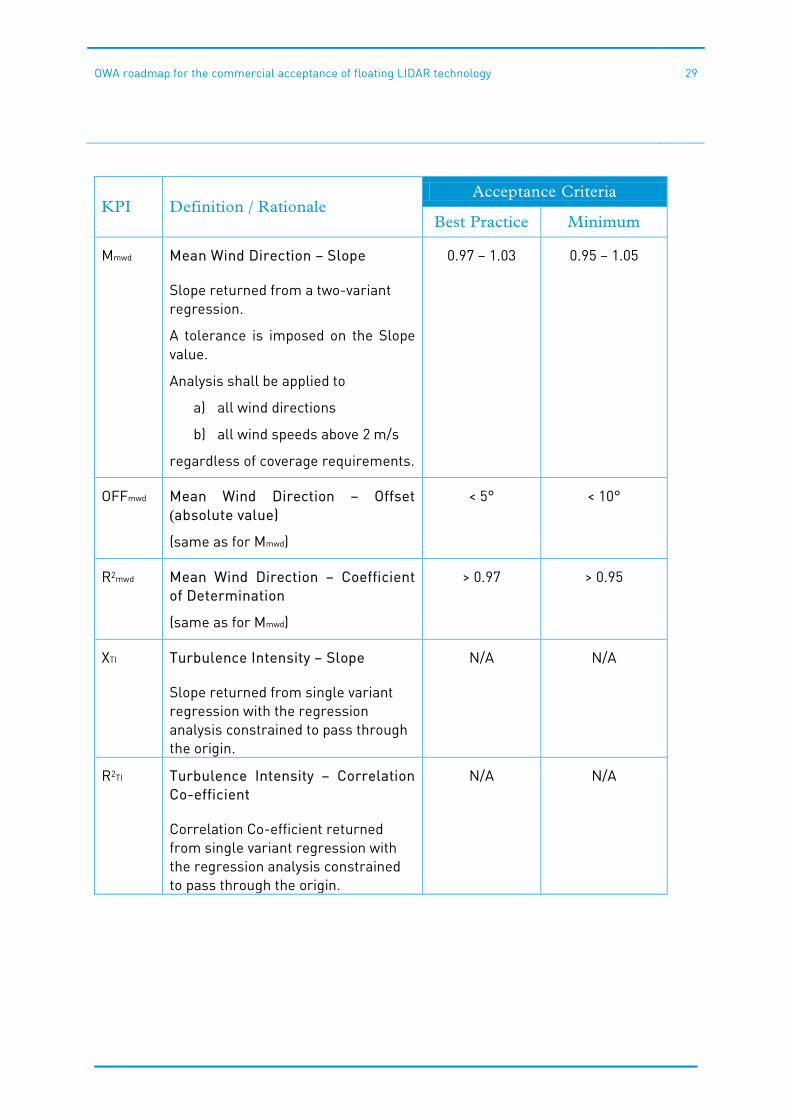
Mmwd Mean Wind Direction – Slope
Slope returned from a two-variant regression.
A tolerance is imposed on the Slope value.
Analysis shall be applied to
a) all wind directions
b) all wind speeds above 2 m/s
regardless of coverage requirements.
0.97 – 1.03 0.95 – 1.05
OFFmwd Mean Wind Direction – Offset (absolute value)
(same as for Mmwd)
< 5° < 10°
R2mwd Mean Wind Direction – Coefficient of Determination
(same as for Mmwd)
> 0.97 > 0.95
XTI Turbulence Intensity – Slope
Slope returned from single variant regression with the regression analysis constrained to pass through the origin.
N/A N/A
R2TI Turbulence Intensity – Correlation Co-efficient
Correlation Co-efficient returned from single variant regression with the regression analysis constrained to pass through the origin.
N/A N/A

OWA roadmap for the commercial acceptance of floating LIDAR technology
30
KPI Definition / Rationale Acceptance Criteria
Best Practice Minimum
A Wind Speed Shear – Shear Exponent Alpha related to Hellman’s power law.
Alpha to be calculated using reference anemometry heights at 50 m and 90 m
Mean Alpha values to be compared for different wind speed ranges such as
a) 4 to 8 m/s
b) 8 to 12 m/s
c) 12 to 16 m/s
d) all wind speeds above 2 m/s
N/A N/A