CARBON STEEL Check-Mate 450 Pumps 308017ZAA...† An air line filter (J) removes harmful dirt and...
42
308017ZAA EN Instructions CARBON STEEL Check-Mate ® 450 Pumps WITH PRIMING PISTON, AND SEVERE-DUTY ROD AND CYLINDER For use with non-heated bulk supply of medium to high viscosity sealant and adhesive materials. For professional use only. Not approved for use in European explosive atmosphere locations. See page 2 for model information, including maximum working pressure. Important Safety Instructions Read all warnings and instructions in this manual before using the equipment. Save these instructions. Model 222768 Shown
Transcript of CARBON STEEL Check-Mate 450 Pumps 308017ZAA...† An air line filter (J) removes harmful dirt and...

308017ZAAEN
Instructions
CARBON STEEL
Check-Mate® 450 PumpsWITH PRIMING PISTON, AND SEVERE-DUTY ROD AND CYLINDER
For use with non-heated bulk supply of medium to high viscosity sealant and adhesivematerials. For professional use only.
Not approved for use in European explosive atmosphere locations.
See page 2 for model information, including maximumworking pressure.
Important Safety InstructionsRead all warnings and instructions in thismanual before using the equipment.Save these instructions.
Model 222768 Shown

Models
2 308017ZAA
ContentsModels . . . . . . . . . . . . . . . . . . . . . . . . . . . . . . . . . . . 2Warnings . . . . . . . . . . . . . . . . . . . . . . . . . . . . . . . . . 3Installation . . . . . . . . . . . . . . . . . . . . . . . . . . . . . . . . 5
System Accessories . . . . . . . . . . . . . . . . . . . . . . 5Grounding . . . . . . . . . . . . . . . . . . . . . . . . . . . . . . 7
Operation . . . . . . . . . . . . . . . . . . . . . . . . . . . . . . . . . 8Pressure Relief Procedure . . . . . . . . . . . . . . . . . 8Packing Nut/Wet-Cup . . . . . . . . . . . . . . . . . . . . . 8Fluid Line Accessories . . . . . . . . . . . . . . . . . . . . 9Starting and Adjusting the Pump . . . . . . . . . . . . 9Shutdown and Care of the Pump . . . . . . . . . . . 10Flushing . . . . . . . . . . . . . . . . . . . . . . . . . . . . . . 10
Troubleshooting . . . . . . . . . . . . . . . . . . . . . . . . . . 11Service . . . . . . . . . . . . . . . . . . . . . . . . . . . . . . . . . . 12
Required Tools . . . . . . . . . . . . . . . . . . . . . . . . . 12Disconnect the Pump . . . . . . . . . . . . . . . . . . . . 12Reconnect the Pump . . . . . . . . . . . . . . . . . . . . 13
Maintenance . . . . . . . . . . . . . . . . . . . . . . . . . . . . . . 14Disassemble and Inspect the Pump . . . . . . . . . 14Reassemble the Pump . . . . . . . . . . . . . . . . . . . 17
Parts . . . . . . . . . . . . . . . . . . . . . . . . . . . . . . . . . . . . 20Displacement Pump . . . . . . . . . . . . . . . . . . . . . 26
Accessories . . . . . . . . . . . . . . . . . . . . . . . . . . . . . . 28Throat Packing Kits . . . . . . . . . . . . . . . . . . . . . . 28
Technical Specifications . . . . . . . . . . . . . . . . . . . . 30President Pumps . . . . . . . . . . . . . . . . . . . . . . . . 30Senator Pumps . . . . . . . . . . . . . . . . . . . . . . . . . 32Quiet Senator Pumps . . . . . . . . . . . . . . . . . . . . 34Bulldog Pumps . . . . . . . . . . . . . . . . . . . . . . . . . 36Quiet Bulldog Pumps . . . . . . . . . . . . . . . . . . . . . 38
Dimensions . . . . . . . . . . . . . . . . . . . . . . . . . . . . . . . 40Mounting Hole Layout . . . . . . . . . . . . . . . . . . . . . . 41Graco Standard Warranty . . . . . . . . . . . . . . . . . . . 42
Models
ModelNo. Description
Maximum AirWorking Pressure
Maximum FluidWorking Pressure
MPa bar psi MPa bar psi
222768 20:1 ratio President® Pump, Series A(UHMWPE/PTFE Packed)
1.2 12 180 25 248 3600
237207 20:1 ratio stubby President® Pump, Series A(UHMWPE/PTFE Packed)
1.2 12 180 25 248 3600
246933 20:1 ratio President® Pump, Series A(Tuffstack Throat Packed)
1.2 12 180 25 248 3600
222769 34:1 ratio Senator® Pump, Series A(UHMWPE/PTFE Packed)
0.8 8 120 28 281 4080
224660 34:1 ratio Quiet Senator® Pump, Series A(UHMWPE/PTFE Packed)
0.8 8 120 28 281 4080
237492 34:1 ratio stubby Senator® Pump, Series A(UHMWPE/PTFE Packed)
0.8 8 120 28 281 4080
237780 34:1 ratio stubby Quiet Senator® Pump,Series A (UHMWPE/PTFE Packed)
0.8 8 120 28 281 4080
222778 55:1 ratio Bulldog® Pump, Series A(UHMWPE/PTFE Packed)
0.6 6.2 90 34 341 4950
222813 55:1 ratio Quiet Bulldog® Pump, Series A(UHMWPE/PTFE Packed)
0.6 6.2 90 34 341 4950
237208 55:1 ratio stubby Bulldog® Pump, Series A(UHMWPE/PTFE Packed)
0.6 6.2 90 34 341 4950
237779 55:1 ratio stubby Quiet Bulldog® Pump,Series A (UHMWPE/PTFE Packed)
0.6 6.2 90 34 341 4950

Warnings
308017ZAA 3
WarningsThe following warnings are for the setup, use, grounding, maintenance, and repair of this equipment. The exclama-tion point symbol alerts you to a general warning and the hazard symbols refer to procedure-specific risks. Whenthese symbols appear in the body of this manual or on warning labels, refer back to these Warnings. Product-specifichazard symbols and warnings not covered in this section may appear throughout the body of this manual whereapplicable.
WARNINGEQUIPMENT MISUSE HAZARDMisuse can cause death or serious injury.• Do not operate the unit when fatigued or under the influence of drugs or alcohol.• Do not exceed the maximum working pressure or temperature rating of the lowest rated system
component. See in all equipment manuals.• Use fluids and solvents that are compatible with equipment wetted parts. See in all equipment
manuals. Read fluid and solvent manufacturer’s warnings. For complete information about yourmaterial, request Safety Data Sheets (SDSs) from distributor or retailer.
• Do not leave the work area while equipment is energized or under pressure.• Turn off all equipment and follow the Pressure Relief Procedure when equipment is not in use.• Check equipment daily. Repair or replace worn or damaged parts immediately with genuine man-
ufacturer’s replacement parts only.• Do not alter or modify equipment. Alterations or modifications may void agency approvals and cre-
ate safety hazards.• Make sure all equipment is rated and approved for the environment in which you are using it.• Use equipment only for its intended purpose. Call your distributor for information.• Route hoses and cables away from traffic areas, sharp edges, moving parts, and hot surfaces.• Do not kink or over bend hoses or use hoses to pull equipment.• Keep children and animals away from work area.• Comply with all applicable safety regulations.
SKIN INJECTION HAZARDHigh-pressure fluid from gun, hose leaks, or ruptured components will pierce skin. This may look likejust a cut, but it is a serious injury that can result in amputation. Get immediate surgical treatment.• Do not spray without tip guard and trigger guard installed.• Engage trigger lock when not spraying.• Do not point gun at anyone or at any part of the body.• Do not put your hand over the spray tip.• Do not stop or deflect leaks with your hand, body, glove, or rag.• Follow the Pressure Relief Procedure when you stop spraying and before cleaning, checking, or
servicing equipment.• Tighten all fluid connections before operating the equipment.• Check hoses and couplings daily. Replace worn or damaged parts immediately.

Warnings
4 308017ZAA
MOVING PARTS HAZARDMoving parts, such as the priming piston, can pinch, cut or amputate fingers and other body parts.• Keep clear of moving parts.• Keep hands and fingers away from the priming piston during operation and whenever the pump is
charged with air.• Do not operate equipment with protective guards or covers removed.• Pressurized equipment can start without warning. Before checking, moving, or servicing equip-
ment, follow the Pressure Relief Procedure and disconnect all power sources.
FIRE AND EXPLOSION HAZARDFlammable fumes, such as solvent and paint fumes, in work area can ignite or explode. Paint orsolvent flowing through the equipment can cause static sparking. To help prevent fire and explosion:• Use equipment only in well-ventilated area.• Eliminate all ignition sources; such as pilot lights, cigarettes, portable electric lamps, and plastic
drop cloths (potential static sparking).• Ground all equipment in the work area. See Grounding instructions.• Never spray or flush solvent at high pressure.• Keep work area free of debris, including solvent, rags and gasoline.• Do not plug or unplug power cords, or turn power or light switches on or off when flammable fumes
are present.• Use only grounded hoses.• Hold gun firmly to side of grounded pail when triggering into pail. Do not use pail liners unless they
are anti-static or conductive.• Stop operation immediately if static sparking occurs or you feel a shock. Do not use equipment
until you identify and correct the problem.• Keep a working fire extinguisher in the work area.
TOXIC FLUID OR FUMES HAZARDToxic fluids or fumes can cause serious injury or death if splashed in the eyes or on skin, inhaled, orswallowed.• Read Safety Data Sheets (SDSs) to know the specific hazards of the fluids you are using.• Store hazardous fluid in approved containers, and dispose of it according to applicable guidelines.
PERSONAL PROTECTIVE EQUIPMENTWear appropriate protective equipment when in the work area to help prevent serious injury, includingeye injury, hearing loss, inhalation of toxic fumes, and burns. Protective equipment includes but is notlimited to:• Protective eyewear, and hearing protection.• Respirators, protective clothing, and gloves as recommended by the fluid and solvent manufac-
turer.
WARNING

Installation
308017ZAA 5
Installation
System Accessories Air Line
Install the following accessories as shown in FIG. 1,using adapters as necessary:
• A red-handled main air bleed valve (V) is requiredin your system to shut off the air supply to andrelieve air pressure in the pump and ram. Whenclosed, the valve will bleed off all air in the ram andpump, and the ram will slowly drop. Be sure thevalve is easily accessible from the pump, and islocated upstream from the air manifold (D). OrderPart No. 113269 for Monark and President Pumps,or 113218 for Senator and Bulldog Pumps.
• The pump air bleed valve (G) is required in yoursystem to relieve air trapped between it and the airmotor when the valve is closed. Be sure the valve iseasily accessible from the pump, and is locateddownstream from the air regulator (H).
• The pump air regulator (H) controls pump speedand outlet pressure by adjusting the air pressure tothe pump. Locate the regulator close to the pump,but upstream from the pump air bleed valve (G).
• An air line lubricator (F) provides automatic airmotor lubrication.
• A pump runaway valve (E) senses when the pumpis running too fast and automatically shuts off the airto the motor. A pump which runs too fast can beseriously damaged.
• An air manifold (D) has a swivel air inlet. It hasports for connecting lines to air accessories, such asthe ram air regulator (T), which controls the airpressure to the ram.
• The air pressure relief valve (Q) limits the air pres-sure to the ram to 10 bar (150 psi).
• The ram director valve (U) controls the raising andlowering of the ram.
• An air line filter (J) removes harmful dirt and mois-ture from the compressed air supply. Also, install adrain valve (W) at the bottom of each air line drop,to drain off moisture.
• A bleed-type air valve (K) isolates the air lineaccessories for servicing. Locate upstream from allother air line accessories.
A red-handled main air bleed valve (V), pump airbleed valve (G), and fluid drain valve (L) are required.These accessories help reduce the risk of seriousinjury, including fluid injection and splashing of fluid inthe eyes or on the skin, and injury from moving partsif you are adjusting or repairing the pump.
The ram will hold pressure if the ram director valve (U)is in the horizontal (neutral) position. To relieve airpressure in the ram, close the red-handled bleedvalve (V) and move the director valve (U) to DOWN.The ram will slowly drop.
The pump air bleed valve (G) relieves air trappedbetween it and the pump after the air is shut off.Trapped air can cause the pump to cycleunexpectedly. Locate the valve close to the pump.
The fluid drain valve (L) assists in relieving fluidpressure in the displacement pump, hose, and gun.Triggering the gun to relieve pressure may not besufficient.

Installation
6 308017ZAA
Fluid Line
Install the following accessories in the positions shownin FIG. 1, using adapters as necessary:
• Install a fluid drain valve (L) in a tee near the pumpfluid outlet. The drain valve is required in your sys-tem to relieve fluid pressure in the displacementpump, hose and gun/valve. Install with the drainvalve pointing down, but so the handle points upwhen the valve is open. Order Part No. 210658 (3/8npt).
• A fluid regulator (M) controls fluid pressure to thegun/valve, and dampens pressure surges.
• A gun or dispense valve (N) dispenses the fluid.The gun shown in FIG. 1 is a high pressure dispens-ing gun for highly viscous fluids.
• A gun/valve swivel (P) allows freer gun/valvemovement.
Air and Fluid Hoses
Be sure all air hoses (S) and fluid hoses (R) are properlysized and pressure-rated for your system. Use onlyelectrically conductive hoses. Fluid hoses must havespring guards on both ends.
NOTE: FIG. 1 is only a guide for selecting and installing system components and accessories. Contact your Gracodistributor for assistance in designing a system to suit your particular needs.
FIG. 1: Typical Installation
05683
A
B
D
E
F
G
JK
Y
R
TL
N
P
S
M
C
W
H
S
V
Q U
KEY
A PumpB 19 Liter (5 Gallon) Air-Powered RamC Wiper PlateD Air ManifoldE Pump Runaway Valve (location shown)F Air Line Lubricator (location shown)G Pump Bleed-Type Air Valve (required, for
pump)H Pump Air RegulatorJ Air Line FilterK Bleed-Type Air Valve (for accessories)L Fluid Drain Valve (required)M Fluid Pressure RegulatorN Airless Spray Gun or Dispensing ValveP Gun/Valve SwivelQ Ram Air Pressure Relief ValveR Electrically Conductive Fluid Supply HoseS Electrically Conductive Air Supply HoseT Ram Air RegulatorU Ram Director ValveV Red-Handled Main Air Bleed ValveW Air LIne Drain ValveY Ground Wire (required)

Installation
308017ZAA 7
Mounting Accessories
Mount the pump (A) to suit the type of installationplanned. Refer to Dimensions (page 40) and MountingHole Layout (page 41).
If you are mounting the pump on a ram (B), refer to themanual supplied with the ram for installation andoperation instructions. The ram shown in FIG. 1 is a19 liter (5 gal.) pail ram, used with a wiper plate (C). Theram shown includes an air regulator (T). It also requiresan air supply hose (S) and an air manifold (D), whichdivides the main air supply into separate lines for thepump and the ram.
By using Pump Mounting Kit 222776, you can alsomount the pump on Floor Stand 222780, 200 liter(55 gal.) Ram 207279, or Inductor 222635.
Grounding
Pump: use a ground wire and clamp. See FIG. 2. Loosenthe grounding lug locknut (W) and washer (X). Insert
one end of a 1.5 mm2 (12 ga) minimum ground wire (Y)into the slot in lug (Z) and tighten the locknut securely.Connect the other end of the wire to a true earth ground.Order Part No. 237569 Ground Wire and Clamp.
Air and fluid hoses: use only electrically conductivehoses.
Air compressor: follow manufacturer’srecommendations.
Spray gun/dispense valve: ground through connectionto a properly grounded fluid hose and pump.
Fluid supply container: follow your local code.
Object being sprayed: follow your local code.
All solvent pails used when flushing: follow your localcode. Use only metal pails, which are conductive,placed on a grounded surface. Do not place the pail ona nonconductive surface, such as paper or cardboard,which interrupts the grounding continuity.
To maintain grounding continuity when flushing orrelieving pressure, always hold a metal part of thegun/valve firmly to the side of a grounded metal pail,then trigger the gun/valve.
The equipment must be grounded to reduce the riskof static sparking. Static sparking can cause fumes toignite or explode. Grounding provides an escape wirefor the electric current.
FIG. 2
W
XY
Z
0864

Operation
8 308017ZAA
Operation
Pressure Relief ProcedureFollow the Pressure Relief Procedure wheneveryou see this symbol.
1. Lock the gun/valve trigger safety.
2. Close the pump’s bleed-type air valve (G, requiredin your system).
3. Shut off the red-handled main air bleed valve(V, required in your system). If the pump is mountedon a ram, set the ram director valve (U) to DOWN.The ram will slowly drop.
4. Unlock the gun/valve trigger safety.
5. Hold a metal part of the gun/valve firmly to the sideof a grounded metal pail, and trigger the gun/valveto relieve pressure.
6. Lock the gun/valve trigger safety.
7. Open the drain valve (required in your system),having a container ready to catch the drainage.
8. Leave the drain valve open until you are ready tospray/dispense again.
If you suspect that the spray tip/nozzle or hose iscompletely clogged, or that pressure has not been fullyrelieved after following the steps above, very slowlyloosen the tip guard retaining nut or hose end couplingand relieve pressure gradually, then loosen completely.Now clear the tip/nozzle or hose.
Packing Nut/Wet-Cup
Before starting, fill the packing nut (2) 1/3 full with GracoThroat Seal Liquid (TSL) or compatible solvent. See FIG.3.
The packing nut is torqued at the factory and is ready foroperation. If it becomes loose and there is leaking fromthe throat packings, relieve pressure, then torque thenut to 45-53 N•m (33-39 ft-lb) using the supplied wrench(110). Do this whenever necessary. Do not overtightenthe packing nut.
This equipment stays pressurized until pressure ismanually relieved. To help prevent serious injury frompressurized fluid, such as skin injection, splashingfluid and moving parts, follow the Pressure ReliefProcedure when you stop spraying and beforecleaning, checking, or servicing the equipment.
FIG. 3
0423A
25
35
2
43
1
110
1
2
2
AA
23
Bleed hole must face down.
Torque to 45–53 N•m (33–39 ft-lb).

Operation
308017ZAA 9
Fluid Line AccessoriesThe pump is tested with lightweight oil, which is left in toprotect the pump parts. If the fluid you are using may becontaminated by the oil, flush it out with a compatiblesolvent. See Flushing, page 10.
Starting and Adjusting the Pump
1. Do not install the spray tip yet.
2. Supply fluid to the pump, per the requirements ofyour system.
3. See FIG. 1. Close the pump air regulator (H).
4. Open the red-handled main air bleed valve (V) andthe pump’s bleed-type air valve (G).
5. Hold a metal part of the gun/valve (N) firmly to theside of a grounded metal pail and hold the triggeropen.
6. Slowly open the air regulator (H) until the pumpstarts.
7. Cycle the pump slowly until all air is pushed out andthe pump and hoses are fully primed.
8. Release the gun/valve trigger and lock the triggersafety. The pump should stall against pressure.
9. If the pump fails to prime properly, open the bleedervalve plug (35) slightly. Use the bleed hole on theunderside of the valve body (43) as a priming valveuntil the fluid appears at the hole. See FIG. 3. Closethe plug (35).
NOTE: When changing fluid containers with the hoseand gun/valve already primed, open the bleeder valveplug (35) to help prime the pump and vent air before itenters the hose. Close the plug when all air is elimi-nated.
10. With the pump and lines primed, and with adequateair pressure and volume supplied, the pump will startand stop as you open and close the gun/valve. In acirculating system, the pump will speed up or slowdown on demand, until the air supply is shut off.
11. Follow the Pressure Relief Procedure, page 8.Install the spray tip in the gun.
See FIG. 3. The priming piston (25) and the air motorpiston (located behind the air motor plates, AA) moveduring operation.
Keep hands and fingers away from the priming piston(25) during operation and whenever the pump ischarged with air. The priming piston extends beyondthe intake cylinder (23) to pull material into the pumpand can amputate a hand or finger caught between itand the intake cylinder. Before checking, clearing, orcleaning the priming piston follow the PressureRelief Procedure on page 8.
Never operate the pump with the air motor plates (AA)removed.
To reduce the risk of fluid injection, do not use yourhand or fingers to cover the bleed hole on theunderside of the bleeder valve body (43) whenpriming the pump. Use a crescent wrench to openand close the bleeder plug (35). Keep your handsaway from the bleed hole.
NOTICE
Do not allow the pump to run dry. It will quicklyaccelerate to a high speed, causing damage. If yourpump is running too fast, stop it immediately andcheck the fluid supply. If the container is empty and airhas been pumped into the lines, refill the container andprime the pump and the lines, or flush and leave itfilled with a compatible solvent. Eliminate all air fromthe fluid system.

Operation
10 308017ZAA
12. Use the air regulator (H) to control the pump speedand the fluid pressure. Always use the lowest airpressure necessary to get the desired results.Higher pressures cause premature tip/nozzle andpump wear.
Shutdown and Care of the Pump
For overnight shutdown, stop the pump at the bottom ofthe stroke to prevent fluid from drying on the exposeddisplacement rod and damaging the throat packings.Relieve the pressure.
Always flush the pump before the fluid dries on thedisplacement rod. Refer to Flushing.
Flushing
Flush with a fluid that is compatible with the fluid you arepumping and with the wetted parts in your system.Check with your fluid manufacturer or supplier forrecommended flushing fluids and flushing frequency.Always flush the pump before fluid dries on thedisplacement rod.
1. Relieve the pressure. Follow the Pressure ReliefProcedure, page 8.
2. Remove the spray tip/nozzle from the gun/valve.
3. Hold a metal part of the gun/valve firmly to the sideof a grounded metal pail.
4. Start the pump. Always use the lowest possible fluidpressure when flushing.
5. Trigger the gun/valve.
6. Flush the system until clear solvent flows from thegun/valve.
7. Relieve the pressure. Follow the Pressure ReliefProcedure, page 8.
COMPONENT RUPTURE HAZARDTo reduce the risk of overpressurizing your system,which could cause component rupture and seriousinjury, never exceed the Maximum Incoming AirPressure to the pump (see the on page 29).
To avoid fire and explosion, always ground equipmentand waste container. To avoid static sparking andinjury from splashing, always flush at the lowest pos-sible pressure.
NOTICE
Never leave water or water-base fluid in the pumpovernight. If you are pumping water-base fluid, flushwith water first, then with a rust inhibitor such asmineral spirits. Relieve the pressure, but leave the rustinhibitor in the pump to protect the parts fromcorrosion.

Troubleshooting
308017ZAA 11
Troubleshooting1. Follow the Pressure Relief Procedure, page 8.
2. Check all possible problems and causes beforedisassembling the pump.
* To determine if the fluid hose or gun is obstructed, follow the Pressure Relief Procedure, page 8. Disconnect thefluid hose and place a container at the pump fluid outlet to catch any fluid. Turn on the air just enough to start thepump. If the pump starts when the air is turned on, the obstruction is in the fluid hose or gun.
PROBLEM CAUSE SOLUTION
Pump fails to operate. Restricted line or inadequate air supply;closed or clogged valves.
Clear; increase the air supply.Check that all valves are open.
Obstructed fluid hose or gun/valve; fluidhose ID is too small.
Open, clear*; use a hose with a larger ID.
Fluid dried on the displacement rod. Clean; always stop the pump at the bottom ofits stroke; keep the wet-cup 1/3 filled with acompatible solvent.
Dirty, worn, or damaged motor parts. Clean or repair; see the separate motormanual.
Pump operates, butoutput is low on bothstrokes.
Restricted line or inadequate air supply;closed or clogged valves.
Clear; increase the air supply.Check that all valves are open.
Obstructed fluid hose or gun/valve; fluidhose ID is too small.
Open, clear*; use a hose with a larger ID.
Bleeder valve is open. Close the valve.
Air is leaking into the supply container. Check the ram plate seal.
Fluid is too heavy for pump priming. Use the bleeder valve (see Starting andAdjusting the Pump, page 9) or use a ram.
Held open or worn intake valve or seals. Clear the valve; replace the seals.
Worn packings in the displacementpump.
Replace the packings.
Pump operates, butoutput is low ondownstroke.
Fluid too heavy for pump priming. Use the bleeder valve (see Starting andAdjusting the Pump, page 9) or use a ram.
Held open or worn intake valve or seals. Clear the valve; replace the seals.
Pump operates, butoutput is low onupstroke.
Held open or worn piston valve or seals. Clear the valve; replace the seals.
Erratic or acceleratedpump speed.
Exhausted fluid supply. Refill and prime.
Fluid is too heavy for pump priming. Use the bleeder valve (see Starting andAdjusting the Pump, page 9) or use a ram.
Held open or worn piston valve or seals. Clear the valve; replace the seals.
Held open or worn priming piston. Clear; service.
Worn packings in the displacementpump.
Replace the packings.

Service
12 308017ZAA
Service
Required Tools• Torque wrench
• Bench vise, with soft jaws
• Rubber mallet
• Hammer
• O-ring pick
• 13 mm (1/2 in.) dia. brass rod
• Set of socket wrenches
• Set of adjustable wrenches
• Pipe wrench
• Packing nut wrench (110, supplied)
• Thread lubricant
• Thread sealant
• 1-1/4 in. crow foot wrench
Disconnect the Pump
1. Flush the pump, if possible. Stop the pump at thebottom of its stroke.
2. Relieve the pressure.
3. Disconnect the air hose. Hold the fluid outlet fitting(8) with a wrench to keep it from being loosenedwhile you disconnect the fluid hose.
4. Remove the pump from its mounting. Disconnectthe displacement pump (107) from the motor (101)as follows. Be sure to note the relative position ofthe pump’s fluid outlet (8) to the motor air inlet (CC).
5. Using an adjustable wrench (or a hammer and rod),unscrew the coupling nut (104) from the connectingrod (103) or air motor shaft. Do not lose or drop thecoupling collars (105). See FIG. 4.
6. Hold the tie rod flats with a wrench to keep the rodsfrom turning. Use the wrench (110) provided withthe pump to unscrew the nuts (106) from the tie rods(102). Carefully remove the displacement pump(107) from the motor (101).
7. Refer to Maintenance, page 14, to service thedisplacement pump. To service the air motor, referto the separate motor manual, supplied.

Service
308017ZAA 13
Reconnect the Pump1. Make sure the coupling nut (104) and the coupling
collars (105) are in place on the displacement rod(1). See FIG. 4.
2. Orient the pump’s fluid outlet (8) to the air inlet (CC)as was noted in step 4 under Disconnecting theDisplacement Pump. Position the displacementpump (107) on the tie rods (102).
NOTE: Refer to FIG. 4 and the Torque Chart for propertorque values for your pump.
3. If you removed the tie rods (102) from the air motor(101), reinstall them using an 11 mm wrench.Torque as specified.
4. Screw the nuts (106) onto the tie rods (102) andtorque as specified.
5. Screw the coupling nut (104) onto the connectingrod (103) or air motor shaft loosely. Hold theconnecting rod flats with a wrench to keep it fromturning. Using an adjustable wrench, torque thecoupling nut.
6. Using a torque wrench in the square hole of thesupplied wrench (110), torque the packing nut (2).
7. Mount the pump and reconnect all hoses.Reconnect the ground wire if it was disconnected.Fill the wet-cup (2) 1/3 full of Graco Throat SealLiquid or compatible solvent.
8. Turn on the air supply. Run the pump slowly toensure proper operation.
9. Before returning the pump to production, relieve thepressure and retorque the packing nut (2).
PUMP TORQUE CHART (Refer to FIG. 4)
PumpModel
Tie Rod(102)
Tie RodNut (106)
CouplingNut (104)
PackingNut (2)
222768,237207,246933
222769,222770,222778,222813,224660,235626
237208,237492,237779,237780
FIG. 4
4 1 3 2
5 1 3 2
7 7 6 2
101
111
103
105
107
8
2
110
2
1
CC
102
104
106
4
3
1
or
or
or 7
6
, 5 ,7
0424B
Torque to 27–34 N•m(20–25 ft-lb).
Torque to 45–53 N•m(33–39 ft-lb).
Torque to 50–61 N•m(37–45 ft-lb).
Torque to 20–25 N•m(15–18 ft-lb).
Torque to 36–45 N•m(27–33 ft-lb).
Torque to 195–210 N•m(145–155 ft-lb).
Torque to 81–89 N•m(60–66 ft-lb).
1
2
3
4
5
6
7
Model 222768President PumpShown

Maintenance
14 308017ZAA
Maintenance
Disassemble and Inspect thePumpWhen disassembling the pump, lay out all removedparts in sequence, to ease reassembly.
NOTE: Repair Kit 222773 is available for DisplacementPumps 222790, 237206, 237450 and 246932. The kitincludes piston and intake seals and cylinder o-rings.For the best results, use all the new parts in the kit. Kitparts are marked with one asterisk *.
Repair Kits 222774 (UHMWPE/PTFE), 222775 (PTFE),237916 (UHMWPE/leather), and 234422(UHMWPE/Tuffstack) are available to replace the throatpackings. For the best results, use all the new parts inthe kit. Kit parts are marked with a †, for example (3†).
Repair Kit 222793 is available to service the intake valveof Displacement Pumps 222790, 237206, 237450 and246932. Kit 25Y247 also is available for the sameDisplacement Pumps, which includes the intake sealsplus the cylinder o-rings (ref. 11). For the best results,use all the new parts in the kit. Kit 222793 parts aremarked with a ‡. Kit 25Y247 parts are marked with a ★.
1. Remove the displacement pump from the air motor.(See Disconnect the Pump, page 12.) Place thepump in a vise, with the jaws on the outlet housing(10).
2. Hold the flats of the priming piston rod (24) with a12 mm wrench. Using a 22 mm wrench, unscrewthe priming piston nut (30). Slide the priming piston(25) and piston guide (31) off the rod. Inspect thesurfaces of the guide (31) and piston (25) forscoring, wear, or other damage.
3. Loosen the packing nut (2) using the wrench (110)supplied, or a hammer and brass rod. Remove theintake cylinder (23), using an adjustable wrench.
4. Unscrew the intake valve housing (17) from thecylinder (12), using an adjustable wrench. Pull thehousing off the pump. The intake check valveassembly (DD) should slide down the priming pistonrod (24) as you remove the housing; if it does notslide easily, firmly tap on the top of the housing (17)with a rubber mallet to loosen.
5. Use an o-ring pick to remove the seal (21) from theintake valve housing (17). Discard the seal; use anew one for reassembly. Pull the intake valve seat(22) out the bottom of the housing (17). If the seat isdifficult to remove, insert a brass rod through the topof the housing and drive the seat out with ahammer. Take care not to drop the check valveassembly (DD) as it comes free, and set it aside forlater.
6. Push the displacement rod (1) down as far aspossible, then pull it and the priming piston rod (24)out of the outlet housing (10) and cylinder (12).
7. Remove the packing nut (2), throat packings(5 and/or 3) and glands (4 and 6) from the outlethousing (10). Some models include a fluid outletnipple (8) and o-ring (9). Do not remove these partsfrom the housing unless they need replacement.
8. Unscrew the bleeder valve plug (35) completelyfrom the valve body (43). Clean the valve threadsand the bleed hole. It is not necessary to remove thevalve body from the pump outlet housing (10).
9. Use a 400 mm adjustable wrench on the flats of thepump cylinder (12) and unscrew the cylinder fromthe outlet housing (10). Remove the o-rings (11).Inspect the inside surface of the cylinder for wear,scoring or other damage by holding it up to the lightat an angle or running a finger over the surface.
10. Inspect the outer surfaces of the displacement rod(1) and priming piston rod (24) for wear, scoring orother damage by holding them up to the light at anangle or running a finger over the surface.
11. Use a vise with soft jaws to hold the displacementrod (1) by its flats. Place a 19 mm wrench on theflats of the piston and unscrew the piston (13) andpriming piston rod (24) from the displacement rod(1). Remove the spacer (33). Disassemble thepiston guide (14) from the piston (13).
12. It is not necessary to remove the priming piston rod(24) from the piston (13) unless your inspectionreveals scoring, wear, or other damage to eitherpart. To disassemble, place the piston flats in a viseand unscrew the rod, using a 12 mm wrench on theflats.

Maintenance
308017ZAA 15
FIG. 5
2
10
11
11
2122
31
30
23
24
4
5or3
6
3
12
1
9
25
35
17
8
2
2
4
35
DD
43
0425B
13
33
14
15
16
19
*20
18
12(Ref)
1(Ref)
24(Ref)
42
DD
17(Ref)
Lips of v-packings must face down.
See Detail at right.
Valve Plug (remove and clean).
Valve Body (do not remove).
Remove only if damaged.
1
2
3
4
5
Throat Packing Detail
Detail of Piston andIntake Check Valve

Maintenance
16 308017ZAA
13. Place the flats of the piston seat (16) in a vise.Using a 13 mm (1/2 in.) dia. brass rod (EE),unscrew the piston guide (14) from the piston seat(16). See FIG. 6. Remove the piston seal (15);always replace with a new one. Inspect the matingsurfaces of the piston (13) and piston seat (16) fornicks, scoring or wear.
14. To disassemble the intake check valve (DD), placethe nut (18) in a vise and unscrew the intake valvebody (19), using a 28 mm wrench. See FIG. 7.Remove the seals (42, 20) from the nut and from thevalve body; always replace them with new ones.Inspect the mating surfaces of the intake valve body(19) and seat (22) for wear, scoring, or otherdamage.
NOTE: The seal (42) is press-fit in the nut (18) and mayrequire cutting to ease removal.
15. Inspect all parts for damage and clean with acompatible solvent. To reassemble, refer toReassemble the Pump, page 17.
FIG. 6
14
16
0205
EE
FIG. 7
19
18
0206

Maintenance
308017ZAA 17
Reassemble the PumpNOTE: Refer to FIG. 8.
1. Place a 13 mm (1/2 in.) diameter brass rodlengthwise in a vise. Install a new piston seal (15*)on the piston seat. Apply thread sealant to thethreads of the piston seat. Place the piston guide(14) securely on the brass rod. Using a 32 mmcrow’s-foot, screw the piston seat (16) into thepiston guide. Torque to 27-34 N•m (20-25 ft-lb).
2. If it was necessary to remove the priming piston rod(24) from the piston (13), apply thread sealant to thethreads of the rod. Place the flats of the piston (13)in a vise. Hold the flats of the rod with a 12 mmwrench, and screw the rod into the piston. Torque to45-53 N•m (33-39 ft-lb).
3. Use a vise with soft jaws to hold the displacementrod (1) by its flats. Install the spacer (33, see thefollowing note) on the rod. Install the assembledpiston guide/seat on the piston (13). Apply threadsealant to the threads of the displacement rod, andscrew the piston assembly onto the rod, using a19 mm wrench on the flats of the piston. Torque to120-130 N•m (88-95 ft-lb). There will be a small gapbetween the top of the piston (13) and the shoulderof the rod (1).
NOTE: The piston spacer (33) is not required whenpumping fluids with a viscosity greater than 1 millioncentipoise.
4. Lubricate the threads of the bleeder valve plug (35).The plug has two sets of threads. Be sure to screwthe plug completely into the valve body (43). Torquethe plug to 30-38 N•m (22-28 ft-lb).
NOTE: Some models include an outlet nipple (8) ando-ring (9*). It is not ordinarily necessary to remove theseparts. However, if they were replaced because of dam-age, lubricate the o-ring and place it on the nipple.Screw the nipple into the outlet housing (10). Torque to70-75 N•m (51-55 ft-lb).
5. Lubricate the o-rings (11*) and install them on thecylinder (12). Apply thread lubricant to the topthreads of the cylinder. Using a 400 mm wrench onthe flats of the cylinder, screw it into the outlethousing (10). Torque to 325-354 N•m (240-260 ft-lb).
6. Lubricate the throat packings and glands, and installthem in the outlet housing (10) one at a time in thefollowing order, with the lips of the v-packingsfacing down: the male gland (6†), v-packings, andthe female gland (4†). Apply thread lubricant to thepacking nut (2) and install the nut loosely in theoutlet housing.
NOTE: Refer to Throat Packing Kits (page 28) for thecorrect throat packing configuration for your pump.
7. Carefully insert the displacement rod (1) into thebottom of the cylinder (12). Push the rod up into thecylinder and through the outlet housing (10), until itprotrudes from the packing nut (2). Be careful not todamage the piston seal (15*) while performing thisstep.
8. Apply thread lubricant to the bottom threads of thecylinder (12). Be sure the o-ring (11*) is in place onthe cylinder. Guide the intake valve housing (17) uponto the priming piston rod (24) and screw it ontothe cylinder, using an adjustable wrench. Torque to325-354 N•m (240-260 ft-lb).
9. With the beveled side facing up, press the seal (42)into the recess of the intake packing nut (18) until itsnaps into place. The nose of the seal should beflush with or slightly recessed into the face of thepacking nut.
10. Apply sealant to the threads of the intake packingnut (18). With the threads facing down toward thepump intake, slide the nut up onto the priming pistonrod (24) until it clears the flats of the rod.
11. Lubricate a new intake valve seal (20*) and slide itonto the rod, being careful not to damage the sealwhen passing over the flats of the rod. Slide the sealup until it reaches the packing nut (18). Applysealant to the female threads of the intake valvebody (19), and slide it onto the rod until it reachesthe nut (18).
12. Place a 26 mm wrench on the flats of the packingnut (18) and a 28 mm wrench on the flats of thevalve body (19). Screw the nut into the body,making certain they remain in position above theflats of the rod (24). Torque to 45-53 N•m (33-39ft-lb). Slide the assembled intake check valve up thepriming piston rod until it reaches the stop (FF); thismay be difficult due to high friction between the sealand rod.
Maintenance
18 308017ZAA
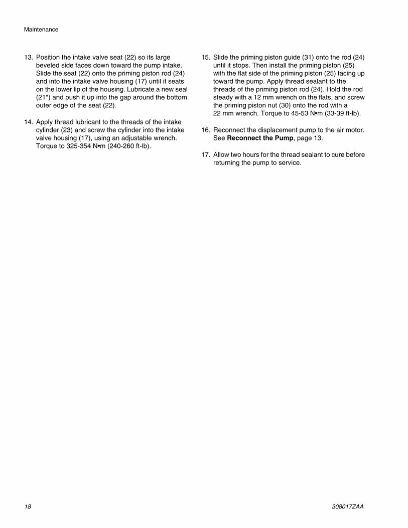
13. Position the intake valve seat (22) so its largebeveled side faces down toward the pump intake.Slide the seat (22) onto the priming piston rod (24)and into the intake valve housing (17) until it seatson the lower lip of the housing. Lubricate a new seal(21*) and push it up into the gap around the bottomouter edge of the seat (22).
14. Apply thread lubricant to the threads of the intakecylinder (23) and screw the cylinder into the intakevalve housing (17), using an adjustable wrench.Torque to 325-354 N•m (240-260 ft-lb).
15. Slide the priming piston guide (31) onto the rod (24)until it stops. Then install the priming piston (25)with the flat side of the priming piston (25) facing uptoward the pump. Apply thread sealant to thethreads of the priming piston rod (24). Hold the rodsteady with a 12 mm wrench on the flats, and screwthe priming piston nut (30) onto the rod with a22 mm wrench. Torque to 45-53 N•m (33-39 ft-lb).
16. Reconnect the displacement pump to the air motor.See Reconnect the Pump, page 13.
17. Allow two hours for the thread sealant to cure beforereturning the pump to service.

Maintenance
308017ZAA 19
FIG. 8
2
10
11*
13
33
14
*15
*11
*2122
31
30
23
16
24
4
5or
3
6
3
12
1
*9
2519
*20
18
0425B
35
12(Ref)
1(Ref)
24(Ref)
17(Ref)
17
42
8
2
2
4
3
1 1
5
5
5
6
7
8
9
9
9
9
10
11
12
12
12
FF
DD
13
13
13
13 13
13
13
43
Lips of v-packings must face down.
See Detail at right.
Lubricate threads and screw completely intobody (43). Torque to 30–38 N•m (22–28 ft-lb).
Valve Body (bleed hole must face down).
Apply thread sealant.
Large bevel must face down.
Flat side must face up.
Torque to 27–34 N•m (20–25 ft-lb).
Torque to 45–53 N•m (33–39 ft-lb).
Torque to 70–75 N•m (51–55 ft-lb).
Torque to 120–130 N•m (88–95 ft-lb).
Torque to 325–354 N•m (240–260 ft-lb).
Lubricate.
1
2
3
4
5
6
7
8
9
10
11
12
13
Throat Packing Detail
Detail of Piston andIntake Check Valve
Parts
20 308017ZAA
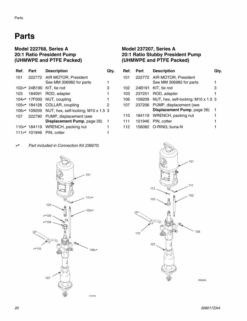
PartsModel 222768, Series A20:1 Ratio President Pump(UHMWPE and PTFE Packed)
Model 237207, Series A20:1 Ratio Stubby President Pump(UHMWPE and PTFE Packed)
Ref. Part Description Qty.
101 222772 AIR MOTOR, PresidentSee MM 306982 for parts 1
102n 24B190 KIT, tie rod 3103 184091 ROD, adapter 1104n 17F000 NUT, coupling 1105n 184128 COLLAR, coupling 2106n 109209 NUT, hex, self-locking; M10 x 1.5 3107 222790 PUMP, displacement (see
Displacement Pump, page 26) 1110n 184119 WRENCH, packing nut 1111n 101946 PIN, cotter 1
n Part included in Connection Kit 236070.
101
111
102
103
104
105
107
106110
ti33926a
Ref. Part Description Qty.
101 222772 AIR MOTOR, PresidentSee MM 306982 for parts 1
102 24B191 KIT, tie rod 3103 237251 ROD, adapter 1106 109209 NUT, hex, self-locking; M10 x 1.5 3107 237206 PUMP, displacement (see
Displacement Pump, page 26) 1110 184119 WRENCH, packing nut 1111 101946 PIN, cotter 1112 156082 O-RING; buna-N 1
05666A
101
103
107
111112
110 106
102

Parts
308017ZAA 21
Model 246933, Series A20:1 Ratio President Pump(Tuffstack Throat Packed)
Ref. Part Description Qty.
101 222772 AIR MOTOR, PresidentSee MM 306982 for parts 1
102n 24B190 KIT, tie rod 3103 184091 ROD, adapter 1104n 17F000 NUT, coupling 1105n 184128 COLLAR, coupling 2106n 109209 NUT, hex, self-locking; M10 x 1.5 3107 246932 PUMP, displacement (see
Displacement Pump, page 26) 1110n 184119 WRENCH, packing nut 1111n 101946 PIN, cotter 1
n Part included in Connection Kit 236070.
101
111
102
103
104
105
107
106110
ti33926a

Parts
22 308017ZAA
Model 222769, Series A34:1 Ratio Senator Pump (shown)(UHMWPE and PTFE Packed)
Model 224660, Series A34:1 Ratio Quiet Senator Pump(UHMWPE and PTFE Packed)
Ref. Part Description Qty.
101 217540 AIR MOTOR, Senator, standardUsed on Model 222769;See MM 307592 for parts 1
220571 AIR MOTOR, Senator, quietUsed on Model 224660;See MM 307592 for parts 1
102n 24B190 KIT, tie rod 3103 184127 ROD, adapter 1104n 17F000 NUT, coupling 1105n 184128 COLLAR, coupling 2106n 109209 NUT, hex, self-locking; M10 x 1.5 3107 222790 PUMP, displacement (see
Displacement Pump, page 26) 1108 184094 PLATE, adapter 1119n 109211 SCREW, cap, socket hd;
5/8–11 unc–2a x 2” (51 mm) 3110n 184119 WRENCH, packing nut 1
n Part included in Connection Kit 236070.
101
102
103
104
105
107
106
109
108
110
ti33927a

Parts
308017ZAA 23
Model 237492, Series A34:1 Ratio Stubby Senator Pump (shown)(UHMWPE and PTFE Packed)
Model 237780, Series A34:1 Ratio Stubby Quiet Senator Pump(UHMWPE and PTFE Packed)
Ref. Part Description Qty.
101 217540 AIR MOTOR, Senator, standardUsed on Model 237492;See MM 307592 for parts 1
220571 AIR MOTOR, Senator, quietUsed on Model 237780;See MM 307592 for parts 1
102n 190000 ROD, tie; 224 mm (8.82”)shoulder to shoulder 3
104n 186925 NUT, coupling 1105n 184129 COLLAR, coupling 2106n 106166 NUT, hex, self-locking; M16 x 2.0 3107 237450 PUMP, displacement (see
Displacement Pump, page 26) 1110n 112887 WRENCH, packing nut 1
n Part included in Connection Kit 235417.
05668B
101
102
104
105
107
106
110

Parts
24 308017ZAA
Model 222778, Series A55:1 Ratio Bulldog Pump (shown)(UHMWPE and PTFE Packed)
Model 222813, Series A55:1 Ratio Quiet Bulldog Pump(UHMWPE and PTFE Packed)
Ref. Part Description Qty.
101 208356 AIR MOTOR, Bulldog, standardUsed on Model 222778;See MM 307049 for parts 1
215255 AIR MOTOR, Bulldog, quietUsed on Model 222813;See MM 307304 for parts 1
102n 24B190 KIT, tie rod 3103 184127 ROD, adapter 1104n 17F000 NUT, coupling 1105n 184128 COLLAR, coupling 2106n 109209 NUT, hex, self-locking; M10 x 1.5 3107 222790 PUMP, displacement (see
Displacement Pump, page 26) 1108 184094 PLATE, adapter 1109n 109211 SCREW, cap, socket hd;
5/8–11 unc–2a x 2” (51 mm) 3110n 184119 WRENCH, packing nut 1
n Part included in Connection Kit 236070.
101
102
103
104
105
107
106
109
108
110
ti33928a

Parts
308017ZAA 25
Model 237208, Series A55:1 Ratio Stubby Bulldog Pump (shown)(UHMWPE and PTFE Packed)
Model 237779, Series A55:1 Ratio Stubby Quiet Bulldog Pump(UHMWPE and PTFE Packed)
Ref. Part Description Qty.
101 208356 AIR MOTOR, Bulldog, standardUsed on Model 237208;See MM 307049 for parts 1
215255 AIR MOTOR, Bulldog, quietUsed on Model 237779;See MM 307304 for parts 1
102n 190000 ROD, tie; 224 mm (8.82”)shoulder to shoulder 3
104n 186925 NUT, coupling 1105n 184129 COLLAR, coupling 2106n 106166 NUT, hex, self-locking; M16 x 2.0 3107 237450 PUMP, displacement (see
Displacement Pump, page 26) 1110n 112887 WRENCH, packing nut 1
n Part included in Connection Kit 235417.110
101
102104
105
107
106
ti33929a

Parts
26 308017ZAA
Displacement PumpNOTE: See Throat Packing Kits, page 28, for replacement throat packings.
Model 222790, Series B Displacement Pump, UHMWPE and PTFE Packings
Model 235540, Series A Displacement Pump, PTFE Packings
Model 237206, Series A Displacement Pump, UHMWPE and PTFE Packings, Stubby Pump
Model 237450, Series A Displacement Pump, UHMWPE and PTFE Packings, Stubby Pump
Model 246932, Series A Displacement Pump, Tuffstack throat, UHMWPE and PTFE Packings
Ref. Part Description Qty.
1 184041 ROD, displacement; sst;328.25 mm (12.92 in.) long;used on Models 222790 &235540 1
190159 ROD, displacement; sst;252.45 mm (9.94 in.) long;used on Model 237206 1
190172 ROD, displacement; sst;328.25 mm (12.92 in.) long;used on Model 237450 1
2 184039 NUT, packing; carbon steel; usedon Models 222790, 235540, and237206 1
236577 NUT, packing; carbon steel; usedon Model 237450 1
7▲ 184090 LABEL, warning 18 184037 NIPPLE, outlet; M30 x 1.5(m);
3/4 npt(m); carbon steel;used on Models 222790,235540, and 237206 only 1
9* 110135 O-RING; PTFE; used on Models222790, 235540, and 237206only 1
10 184038 HOUSING, outlet; ductile iron;used on Models 222790, 235540,and 237206 1
189389 HOUSING, outlet; ductile iron;used on Model 237450 1
11*★ 109205 O-RING; PTFE 212 184040 CYLINDER, pump; sst 113 184042 PISTON; alloy steel 114 184043 GUIDE, piston; alloy steel 115* 184053 SEAL, piston; UHMWPE; used
on Models 222790, 237450, and237206 1
188257 SEAL, piston; PTFE; used onModel 235540; (not included inRepair Kit 222773) 1
16 184052 SEAT, piston; alloy steel 1
17 184044 HOUSING, intake valve; ductileiron 1
18 184493 NUT, packing, intake valve;carbon steel 1
19‡★ 184616 VALVE BODY, intake; alloy steel 120*‡★ 184049 SEAL, intake valve; PTFE 121*‡★ 187860 SEAL; acetal 122‡★ 184617 SEAT, intake valve; alloy steel 123 187859 CYLINDER, intake; ductile iron 124 187858 ROD, priming piston; sst 125 184051 PISTON, priming; carbon steel 130 184121 NUT, priming piston; alloy steel 131 184122 GUIDE, priming piston; alloy steel 133 184124 SPACER, piston; sst 135 190128 PLUG, bleeder valve 137▲ 184151 LABEL, warning 139▲ 172479 TAG, warning (not shown) 142*‡★ 184469 SEAL, intake valve; UHMWPE;
used on Models 222790, 237450,and 237206 1
189217 SEAL, intake valve; PTFE; usedon Model 235540; (not includedin Repair Kits 222773 and222793) 1
43 165702 BODY, bleeder valve 1
* Part included in Seal Repair Kit 222773(purchased separately).
★ Part included in Displacement Pump Seal Kit25A247 (purchased separately).
‡ Part included in Intake Seat Repair Kit 222793(purchased separately).
▲ Replacement Danger and Warning labels, tagsand cards are available at no cost.
Ref. Part Description Qty.

Parts
308017ZAA 27
ti33939a
1 (Ref)
*9
10
*11
13
14
15*
3320*
24 (Ref)
31
42*
2
8
12
35
1
24
17
23
25
30
22
19
18
16
*11
21*
1
2
32
43
4
4
7
26
26
37
WARNING
Refer to Throat Packing Kits, page 28, for available throat packing kits.
Seal Repair Kit 222773 does not include Piston Seal 188257 or Intake Valve Seal 189217 used on pump 235540.
Intake Seat Repair Kit 222793 does not include Intake Valve Seal 189217 used on pump 235540.
Used on Models 222790, 235540, and 237206 only.
1
2
3
4
Model 222790 Shown

Accessories
28 308017ZAA
AccessoriesThroat Packing KitsUHMWPE and PTFE Throat Packing Repair Kit 222774for Displacement Pumps 222790, 237206, and 237450
PTFE Throat Packing Repair Kit 222775for Displacement Pump 235540
UHMWPE and Leather Throat Packing Conversion Kit 237916for use with all Displacement Pumps
Tuffstack and UHMWPE Throat Packing Conversion Kit 234422for Displacement Pump 246932
Ref. Part Description Qty. Lips of v-packings must face down.
3† 109302 V-PACKING; PTFE 24† 184172 GLAND, female; sst 15† 109252 V-PACKING; UHMWPE 36† 184222 GLAND, male; sst 1
† These parts are included in Throat Packing RepairKit 222774, which may be purchased separately.
Ref. Part Description Qty. Lips of v-packings must face down.
3† 109302 V-PACKING; PTFE 54† 184172 GLAND, female; sst 16† 184222 GLAND, male; sst 1
† These parts are included in Throat Packing RepairKit 222775, which may be purchased separately.
Ref. Part Description Qty. Lips of v-packings must face down.
3† 184302 V-PACKING; leather 24† 184172 GLAND, female; sst 15† 109252 V-PACKING; UHMWPE 36† 184222 GLAND, male; sst 1
† These parts are included in Throat Packing RepairKit 237916, which may be purchased separately.
Ref. Part Description Qty. Lips of v-packings must face down.
3† 109327 V-PACKING; Tuffstack 24† 184172 GLAND, female; sst 15† 109252 V-PACKING; UHMWPE 36† 184222 GLAND, male; sst 1
† These parts are included in Throat Packing RepairKit 234422, which may be purchased separately.
4
5
6
4
34 4
4
36
4
4
4
5
6
4
34 4
4
5
6
4
34 4

Accessories
308017ZAA 29

Technical Specifications
30 308017ZAA
Technical Specifications
President Pumps
Sound Pressure Levels (dBa)(measured at 1 meter from unit)
Sound Power Levels (dBa)(tested in accordance with ISO 9614-2)
Be sure that all fluids and solvents used arechemically compatible with the wetted parts listedbelow. Always read the manufacturer’s literaturebefore using fluid or solvent in this pump.
Category Data
Ratio 20:1
Maximum fluid working pressure 25 MPa, 248 bar (3600 psi)
Maximum air input pressure 1.2 MPa, 12 bar (180 psi)
Pump cycles per 3.8 liters (1 gal.) 48
Fluid flow at 60 cycles/min 4.5 liters/min (1.2 gpm)
Air motor effective diameter 108 mm (4.25”)
Stroke length 102 mm (4”)
Displacement pump effective area 4.5 cm2 (0.697 in.2)
Maximum pump operating temperature 82°C (180°F)
Weight 22.7 kg (50 lb)
Wetted parts Carbon Steel; E52100, 41L40, and 4140 Alloy Steel;304, 316 and 17-4 PH Grades of Stainless Steel; DuctileIron; Zinc and Nickel Plating; PTFE; Acetal; Ultra-HighMolecular Weight Polyethylene (not used on Displace-ment Pump 235540)
Air Motor
Input Air Pressures at 15 cycles per minute
40 psi (0.28 MPa, 2.8 bar) 70 psi (0.48 MPa, 4.8 bar) 100 psi (0.7 MPa, 7 bar)
President 73.6 dB(A) 78.3 dB(A) 80.9 dB(A)
Air Motor
Input Air Pressures at 15 cycles per minute
40 psi (0.28 MPa, 2.8 bar) 70 psi (0.48 MPa, 4.8 bar) 100 psi (0.7 MPa, 7 bar)
President 87.4 dB(A) 92.1 dB(A) 94.6 dB(A)

Technical Specifications
308017ZAA 31
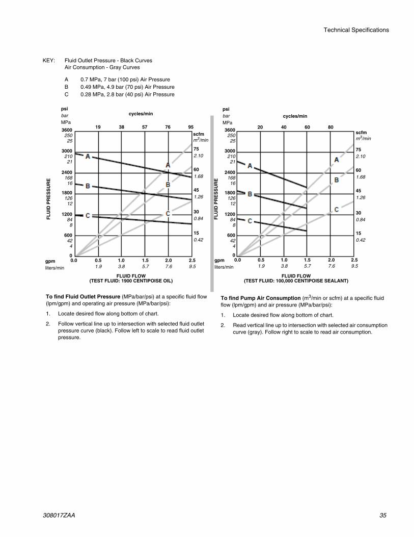
KEY: Fluid Outlet Pressure - Black CurvesAir Consumption - Gray Curves
A 1.2 MPa, 12 bar (180 psi) Air PressureB 0.7 MPa, 7 bar (100 psi) Air PressureC 0.49 MPa, 4.9 bar (70 psi) Air PressureD 0.28 MPa, 2.8 bar (40 psi) Air Pressure
cycles/min
FL
UID
PR
ES
SU
RE
FL
UID
PR
ES
SU
RE
FLUID FLOW(TEST FLUID: 1900 CENTIPOISE OIL)
FLUID FLOW(TEST FLUID: 100,000 CENTIPOISE SEALANT)
psibarMPa
3600250
25
3000210
21
2400168
16
1800126
12
1200848
600424
0gpmliters/min
0.51.9
1.03.8
1.55.7
scfmm3/min
752.10
601.68
451.26
300.84
150.42
24 48 96cycles/min
psibarMPa
scfmm3/min
752.10
601.68
451.26
300.84
150.42
25 7550
0.0
To find Fluid Outlet Pressure (MPa/bar/psi) at a specific fluid flow(lpm/gpm) and operating air pressure (MPa/bar/psi):
1. Locate desired flow along bottom of chart.
2. Follow vertical line up to intersection with selected fluid outletpressure curve (black). Follow left to scale to read fluid outletpressure.
To find Pump Air Consumption (m3/min or scfm) at a specific fluidflow (lpm/gpm) and air pressure (MPa/bar/psi):
1. Locate desired flow along bottom of chart.
2. Read vertical line up to intersection with selected air consumptioncurve (gray). Follow right to scale to read air consumption.
72
2.07.6
3600250
25
3000210
21
2400168
16
1800126
12
1200848
600424
0gpmliters/min
0.51.9
1.03.8
1.55.7
0.0 2.07.6

Technical Specifications
32 308017ZAA
Senator Pumps
Sound Pressure Levels (dBa)(measured at 1 meter from unit)
Sound Power Levels (dBa)(tested in accordance with ISO 9614-2)
Category Data
Ratio 34:1
Maximum fluid working pressure 28 MPa, 281 bar (4080 psi)
Maximum air input pressure 0.8 MPa, 8 bar (120 psi)
Pump cycles per 3.8 liters (1 gal.) 38
Fluid flow at 60 cycles/min 6 liters/min (1.6 gpm)
Air motor effective diameter 146 mm (5.75”)
Stroke length 120 mm (4.7”)
Displacement pump effective area 4.5 cm2 (0.697 in.2)
Maximum pump operating temperature 82°C (180°F)
Weight 45.5 kg (100 lb)
Wetted parts Carbon Steel; E52100, 41L40, and 4140 Alloy Steel;304, 316 and 17-4 PH Grades of Stainless Steel; DuctileIron; Zinc and Nickel Plating; PTFE; Acetal; Ultra-HighMolecular Weight Polyethylene (not used on Displace-ment Pump 235540)
Air Motor
Input Air Pressures at 15 cycles per minute
40 psi (0.28 MPa, 2.8 bar) 70 psi (0.48 MPa, 4.8 bar) 100 psi (0.7 MPa, 7 bar)
Senator 84.3 dB(A) 87.8 dB(A) 91.2 dB(A)
Air Motor
Input Air Pressures at 15 cycles per minute
40 psi (0.28 MPa, 2.8 bar) 70 psi (0.48 MPa, 4.8 bar) 100 psi (0.7 MPa, 7 bar)
Senator 91.6 dB(A) 94.6 dB(A) 97.3 dB(A)

Technical Specifications
308017ZAA 33
KEY: Fluid Outlet Pressure - Black CurvesAir Consumption - Gray Curves
A 0.7 MPa, 7 bar (100 psi) Air PressureB 0.49 MPa, 4.9 bar (70 psi) Air PressureC 0.28 MPa, 2.8 bar (40 psi) Air Pressure
cycles/min
FL
UID
PR
ES
SU
RE
FL
UID
PR
ES
SU
RE
FLUID FLOW(TEST FLUID: 1900 CENTIPOISE OIL)
FLUID FLOW(TEST FLUID: 100,000 CENTIPOISE SEALANT)
psibarMPa
3600250
25
3000210
21
2400168
16
1800126
12
1200848
600424
0gpmliters/min
0.51.9
1.03.8
1.55.7
scfmm3/min
752.10
601.68
451.26
300.84
150.42
24 48 96cycles/min
psibarMPa
scfmm3/min
752.10
601.68
451.26
300.84
150.42
20 8040
0.0
To find Fluid Outlet Pressure (MPa/bar/psi) at a specific fluid flow(lpm/gpm) and operating air pressure (MPa/bar/psi):
1. Locate desired flow along bottom of chart.
2. Follow vertical line up to intersection with selected fluid outletpressure curve (black). Follow left to scale to read fluid outletpressure.
To find Pump Air Consumption (m3/min or scfm) at a specific fluidflow (lpm/gpm) and air pressure (MPa/bar/psi):
1. Locate desired flow along bottom of chart.
2. Read vertical line up to intersection with selected air consumptioncurve (gray). Follow right to scale to read air consumption.
72
2.07.6
3600250
25
3000210
21
2400168
16
1800126
12
1200848
600424
0gpmliters/min
0.51.9
1.03.8
1.55.7
0.0 2.07.6
2.59.5
60
2.59.5

Technical Specifications
34 308017ZAA
Quiet Senator Pumps
Sound Pressure Levels (dBa)(measured at 1 meter from unit)
Sound Power Levels (dBa)(tested in accordance with ISO 9614-2)
Category Data
Ratio 34:1
Maximum fluid working pressure 28 MPa, 281 bar (4080 psi)
Maximum air input pressure 0.8 MPa, 8 bar (120 psi)
Pump cycles per 3.8 liters (1 gal.) 38
Fluid flow at 60 cycles/min 6 liters/min (1.6 gpm)
Air motor effective diameter 146 mm (5.75”)
Stroke length 120 mm (4.7”)
Displacement pump effective area 4.5 cm2 (0.697 in.2)
Maximum pump operating temperature 82°C (180°F)
Weight 45.5 kg (100 lb)
Wetted parts Carbon Steel; E52100, 41L40, and 4140 Alloy Steel;304, 316 and 17-4 PH Grades of Stainless Steel; DuctileIron; Zinc and Nickel Plating; PTFE; Acetal; Ultra-HighMolecular Weight Polyethylene (not used on Displace-ment Pump 235540)
Air Motor
Input Air Pressures at 15 cycles per minute
40 psi (0.28 MPa, 2.8 bar) 70 psi (0.48 MPa, 4.8 bar) 100 psi (0.7 MPa, 7 bar)
Quiet Senator 83.4 dB(A) 84.3 dB(A) 88.5 dB(A)
Air Motor
Input Air Pressures at 15 cycles per minute
40 psi (0.28 MPa, 2.8 bar) 70 psi (0.48 MPa, 4.8 bar) 100 psi (0.7 MPa, 7 bar)
Quiet Senator 89.8 dB(A) 91.8 dB(A) 94.4 dB(A)
Technical Specifications
308017ZAA 35
KEY: Fluid Outlet Pressure - Black CurvesAir Consumption - Gray Curves
A 0.7 MPa, 7 bar (100 psi) Air PressureB 0.49 MPa, 4.9 bar (70 psi) Air PressureC 0.28 MPa, 2.8 bar (40 psi) Air Pressure
cycles/min
FL
UID
PR
ES
SU
RE
FL
UID
PR
ES
SU
RE
FLUID FLOW(TEST FLUID: 1900 CENTIPOISE OIL)
FLUID FLOW(TEST FLUID: 100,000 CENTIPOISE SEALANT)
psibarMPa
360025025
300021021
240016816
180012612
1200848
600424
0gpmliters/min
0.51.9
1.03.8
1.55.7
scfmm3/min
752.10
601.68
451.26
300.84
150.42
19 38 76
cycles/minpsibarMPa
scfmm3/min
752.10
601.68
451.26
300.84
150.42
20 8040
0.0
To find Fluid Outlet Pressure (MPa/bar/psi) at a specific fluid flow(lpm/gpm) and operating air pressure (MPa/bar/psi):
1. Locate desired flow along bottom of chart.
2. Follow vertical line up to intersection with selected fluid outletpressure curve (black). Follow left to scale to read fluid outletpressure.
To find Pump Air Consumption (m3/min or scfm) at a specific fluidflow (lpm/gpm) and air pressure (MPa/bar/psi):
1. Locate desired flow along bottom of chart.
2. Read vertical line up to intersection with selected air consumptioncurve (gray). Follow right to scale to read air consumption.
57
2.07.6
360025025
300021021
240016816
180012612
1200848
600424
0gpmliters/min
0.51.9
1.03.8
1.55.7
0.0 2.07.6
2.59.5
60
2.59.5
95

Technical Specifications
36 308017ZAA
Bulldog Pumps
Sound Pressure Levels (dBa)(measured at 1 meter from unit)
Sound Power Levels (dBa)(tested in accordance with ISO 9614-2)
Category Data
Ratio 55:1
Maximum fluid working pressure 34 MPa, 341 bar (4950 psi)
Maximum air input pressure 0.6 MPa, 6.2 bar (90 psi)
Pump cycles per 3.8 liters (1 gal.) 40
Fluid flow at 60 cycles/min 5.7 liters/min (1.5 gpm)
Air motor effective diameter 146 mm (5.75”)
Stroke length 120 mm (4.7”)
Displacement pump effective area 4.5 cm2 (0.697 in.2)
Maximum pump operating temperature 82°C (180°F)
Weight 45.5 kg (100 lb)
Wetted parts Carbon Steel; E52100, 41L40, and 4140 Alloy Steel;304, 316 and 17-4 PH Grades of Stainless Steel; DuctileIron; Zinc and Nickel Plating; PTFE; Acetal; Ultra-HighMolecular Weight Polyethylene (not used on Displace-ment Pump 235540)
Air Motor
Input Air Pressures at 15 cycles per minute
40 psi (0.28 MPa, 2.8 bar) 70 psi (0.48 MPa, 4.8 bar) 100 psi (0.7 MPa, 7 bar)
Bulldog 82.4 dB(A) 87.3 dB(A) 88.5 dB(A)
Air Motor
Input Air Pressures at 15 cycles per minute
40 psi (0.28 MPa, 2.8 bar) 70 psi (0.48 MPa, 4.8 bar) 100 psi (0.7 MPa, 7 bar)
Bulldog 91.6 dB(A) 95.9 dB(A) 97.4 dB(A)

Technical Specifications
308017ZAA 37
KEY: Fluid Outlet Pressure - Black CurvesAir Consumption - Gray Curves
A 0.6 MPa, 6.2 bar (90 psi) Air PressureB 0.49 MPa, 4.9 bar (70 psi) Air PressureC 0.28 MPa, 2.8 bar (40 psi) Air Pressure
cycles/min
FL
UID
PR
ES
SU
RE
FL
UID
PR
ES
SU
RE
FLUID FLOW(TEST FLUID: 1900 CENTIPOISE OIL)
FLUID FLOW(TEST FLUID: 100,000 CENTIPOISE SEALANT)
psibarMPa
0gpmliters/min
0.51.9
1.03.8
1.55.7
scfmm3/min
20 40 80
cycles/minpsibarMPa
scfmm3/min
1203.36
902.52
601.68
300.84
20 8040
0.0
To find Fluid Outlet Pressure (MPa/bar/psi) at a specific fluid flow(lpm/gpm) and operating air pressure (MPa/bar/psi):
1. Locate desired flow along bottom of chart.
2. Follow vertical line up to intersection with selected fluid outletpressure curve (black). Follow left to scale to read fluid outletpressure.
To find Pump Air Consumption (m3/min or scfm) at a specific fluidflow (lpm/gpm) and air pressure (MPa/bar/psi):
1. Locate desired flow along bottom of chart.
2. Read vertical line up to intersection with selected air consumptioncurve (gray). Follow right to scale to read air consumption.
60
2.07.6
500035035
400028028
300021021
200014014
1000707
0gpmliters/min
0.51.9
1.03.8
1.55.7
0.0 2.07.6
2.59.5
60
2.59.5
1203.36
902.52
601.68
300.84
500035035
400028028
300021021
200014014
1000707

Technical Specifications
38 308017ZAA
Quiet Bulldog Pumps
Sound Pressure Levels (dBa)(measured at 1 meter from unit)
Sound Power Levels (dBa)(tested in accordance with ISO 9614-2)
Category Data
Ratio 55:1
Maximum fluid working pressure 34 MPa, 341 bar (4950 psi)
Maximum air input pressure 0.6 MPa, 6.2 bar (90 psi)
Pump cycles per 3.8 liters (1 gal.) 40
Fluid flow at 60 cycles/min 5.7 liters/min (1.5 gpm)
Air motor effective diameter 146 mm (5.75”)
Stroke length 120 mm (4.7”)
Displacement pump effective area 4.5 cm2 (0.697 in.2)
Maximum pump operating temperature 82°C (180°F)
Weight 45.5 kg (100 lb)
Wetted parts Carbon Steel; E52100, 41L40, and 4140 Alloy Steel;304, 316 and 17-4 PH Grades of Stainless Steel; DuctileIron; Zinc and Nickel Plating; PTFE; Acetal; Ultra-HighMolecular Weight Polyethylene (not used on Displace-ment Pump 235540)
Air Motor
Input Air Pressures at 15 cycles per minute
40 psi (0.28 MPa, 2.8 bar) 70 psi (0.48 MPa, 4.8 bar) 100 psi (0.7 MPa, 7 bar)
Quiet Bulldog 81.5 dB(A) 83.6 dB(A) 85.6 dB(A)
Air Motor
Input Air Pressures at 15 cycles per minute
40 psi (0.28 MPa, 2.8 bar) 70 psi (0.48 MPa, 4.8 bar) 100 psi (0.7 MPa, 7 bar)
Quiet Bulldog 90.2 dB(A) 93.5 dB(A) 94.9 dB(A)

Technical Specifications
308017ZAA 39
KEY: Fluid Outlet Pressure - Black CurvesAir Consumption - Gray Curves
A 0.6 MPa, 6.2 bar (90 psi) Air PressureB 0.49 MPa, 4.9 bar (70 psi) Air PressureC 0.28 MPa, 2.8 bar (40 psi) Air Pressure
cycles/min
FL
UID
PR
ES
SU
RE
FL
UID
PR
ES
SU
RE
FLUID FLOW(TEST FLUID: 1900 CENTIPOISE OIL)
FLUID FLOW(TEST FLUID: 100,000 CENTIPOISE SEALANT)
psibarMPa
0gpmliters/min
0.51.9
1.03.8
1.55.7
scfmm3/min
20 40 80
cycles/minpsibarMPa
scfmm3/min
1203.36
902.52
601.68
300.84
20 8040
0.0
To find Fluid Outlet Pressure (MPa/bar/psi) at a specific fluid flow(lpm/gpm) and operating air pressure (MPa/bar/psi):
1. Locate desired flow along bottom of chart.
2. Follow vertical line up to intersection with selected fluid outletpressure curve (black). Follow left to scale to read fluid outletpressure.
To find Pump Air Consumption (m3/min or scfm) at a specific fluidflow (lpm/gpm) and air pressure (MPa/bar/psi):
1. Locate desired flow along bottom of chart.
2. Read vertical line up to intersection with selected air consumptioncurve (gray). Follow right to scale to read air consumption.
60
2.07.6
500035035
400028028
300021021
200014014
100070
7
0gpmliters/min
0.51.9
1.03.8
1.55.7
0.0 2.07.6
2.59.5
60
2.59.5
1203.36
902.52
601.68
300.84
5000350
35
4000280
28
3000210
21
2000140
14
1000707

Dimensions
40 308017ZAA
Dimensions
PumpModel
A B C D E(air inlet)
F(fluid outlet)
222768,246932
1251 mm(49.25 in.)
418 mm(16.45 in.)
832 mm(32.75 in.)
328 mm(12.9 in.)
1/2 npt(f) 3/4 npt(m)
237207 1119 mm(44.07 in.)
418 mm(16.45 in.)
700 mm(27.57 in.)
196 mm(7.7 in.)
1/2 npt(f) 3/4 npt(m)
222769,224660
1400 mm(55.1 in.)
570 mm(22.4 in.)
830 mm(32.7 in.)
322 mm(12.7 in.)
3/4 npsm(f) 3/4 npt(m)
237492 1329 mm(52.32 in.)
570 mm(22.4 in.)
759 mm(29.88 in.)
251 mm(9.9 in.)
3/4 npsm(f) 3/4 npt(f)
237780 1329 mm(52.32 in.)
570 mm(22.4 in.)
759 mm(29.88 in.)
251 mm(9.9 in.)
3/4 npsm(f) 3/4 npt(f)
222778,222813
1400 mm(55.1 in.)
570 mm(22.4 in.)
830 mm(32.7 in.)
322 mm(12.7 in.)
3/4 npsm(f) 3/4 npt(m)
237208 1329 mm(52.32 in.)
570 mm(22.4 in.)
759 mm(29.88 in.)
251 mm(9.9 in.)
3/4 npsm(f) 3/4 npt(f)
237779 1329 mm(52.32 in.)
570 mm(22.4 in.)
759 mm(29.88 in.)
251 mm(9.9 in.)
3/4 npsm(f) 3/4 npt(f)
0423A
A
B
C
D
E
F
Model 222768 Shown

Mounting Hole Layout
308017ZAA 41
Mounting Hole Layout
PRESIDENT PUMPS
63.5 mm(2.50 in.)
54.1 mm(2.130 in.)
31.25 mm(1.230 in.)
62.50 mm(2.461 in.)
7.9 mm(0.312 in.)diameter (2)
11.4 mm(0.449 in.)
diameter (3)0213
0431
SENATOR AND BULLDOG PUMPS
94.28 mm(3.712 in.)
54.13 mm(2.131 in.
17 mm(0.669 in.)diameter (3)
62.50 mm(2.461 in.)
11.5 mm(0.453 in.)diameter (4)
88 mm(3.464 in.)
94.28 mm(3.712 in.)
50.8 mm(2.0 in.)
31.25 mm(1.230 in.)
101.6 mm(4.0 in.)

All written and visual data contained in this document reflects the latest product information available at the time of publication.Graco reserves the right to make changes at any time without notice.
This manual contains English. MM 308017Graco Headquarters: Minneapolis
International Offices: Belgium, China, Japan, Korea
GRACO INC. AND SUBSIDIARIES • P.O. BOX 1441 • MINNEAPOLIS MN 55440-1441 • USACopyright 2016, Graco Inc. All Graco manufacturing locations are registered to ISO 9001.
www.graco.comRevision ZAA, January 2020
Graco Standard WarrantyGraco warrants all equipment referenced in this document which is manufactured by Graco and bearing its name to be free from defects inmaterial and workmanship on the date of sale to the original purchaser for use. With the exception of any special, extended, or limited warrantypublished by Graco, Graco will, for a period of twelve months from the date of sale, repair or replace any part of the equipment determined byGraco to be defective. This warranty applies only when the equipment is installed, operated and maintained in accordance with Graco’s writtenrecommendations.
This warranty does not cover, and Graco shall not be liable for general wear and tear, or any malfunction, damage or wear caused by faultyinstallation, misapplication, abrasion, corrosion, inadequate or improper maintenance, negligence, accident, tampering, or substitution ofnon-Graco component parts. Nor shall Graco be liable for malfunction, damage or wear caused by the incompatibility of Graco equipment withstructures, accessories, equipment or materials not supplied by Graco, or the improper design, manufacture, installation, operation ormaintenance of structures, accessories, equipment or materials not supplied by Graco.
This warranty is conditioned upon the prepaid return of the equipment claimed to be defective to an authorized Graco distributor for verification ofthe claimed defect. If the claimed defect is verified, Graco will repair or replace free of charge any defective parts. The equipment will be returnedto the original purchaser transportation prepaid. If inspection of the equipment does not disclose any defect in material or workmanship, repairswill be made at a reasonable charge, which charges may include the costs of parts, labor, and transportation.
THIS WARRANTY IS EXCLUSIVE, AND IS IN LIEU OF ANY OTHER WARRANTIES, EXPRESS OR IMPLIED, INCLUDING BUT NOTLIMITED TO WARRANTY OF MERCHANTABILITY OR WARRANTY OF FITNESS FOR A PARTICULAR PURPOSE.
Graco’s sole obligation and buyer’s sole remedy for any breach of warranty shall be as set forth above. The buyer agrees that no other remedy(including, but not limited to, incidental or consequential damages for lost profits, lost sales, injury to person or property, or any other incidental orconsequential loss) shall be available. Any action for breach of warranty must be brought within two (2) years of the date of sale.
GRACO MAKES NO WARRANTY, AND DISCLAIMS ALL IMPLIED WARRANTIES OF MERCHANTABILITY AND FITNESS FOR APARTICULAR PURPOSE, IN CONNECTION WITH ACCESSORIES, EQUIPMENT, MATERIALS OR COMPONENTS SOLD BUT NOTMANUFACTURED BY GRACO. These items sold, but not manufactured by Graco (such as electric motors, switches, hose, etc.), are subject tothe warranty, if any, of their manufacturer. Graco will provide purchaser with reasonable assistance in making any claim for breach of thesewarranties.
In no event will Graco be liable for indirect, incidental, special or consequential damages resulting from Graco supplying equipment hereunder, orthe furnishing, performance, or use of any products or other goods sold hereto, whether due to a breach of contract, breach of warranty, thenegligence of Graco, or otherwise.
FOR GRACO CANADA CUSTOMERSThe Parties acknowledge that they have required that the present document, as well as all documents, notices and legal proceedings entered into,given or instituted pursuant hereto or relating directly or indirectly hereto, be drawn up in English. Les parties reconnaissent avoir convenu que larédaction du présente document sera en Anglais, ainsi que tous documents, avis et procédures judiciaires exécutés, donnés ou intentés, à la suitede ou en rapport, directement ou indirectement, avec les procédures concernées.
Graco InformationFor the latest information about Graco products, visit www.graco.com.For patent information, see www.graco.com/patents.
TO PLACE AN ORDER, contact your Graco distributor or call to identify the nearest distributor.Phone: 612-623-6921 or Toll Free: 1-800-328-0211 Fax: 612-378-3505