multiwall carbon nanotubes alter the thermal profile and antibiotic elution of orthopaedic bone

Volume 16, Number 1Spring 2010
electronics-cooling.com
Carbon nanotubes as high performance thermal interface materials
Electronics cooling in the automotive environment
A case study to demonstrate the trade-offs between liquid and two-phase cooling schemes for small-channel heat sinks in high
heat flux applications

electronics-cooling.com ElectronicsCooling 1
Editorial Board
Associate Technical EditorsBruce Guenin, Ph.D.Principal Hardware EngineerOracleEmail: [email protected]
Clemens Lasance, IRPrincipal Scientist - RetiredConsultant at SomelikeitCoolEmail: [email protected]
Jim Wilson, Ph.D., P.E. Engineering Fellow Raytheon Company Email: [email protected]
Robert SimonsSenior Technical Staff Member - RetiredIBMEmail: [email protected]
ResearcherGary WolfeWolfe Communications43 Partridge StreetFranklin, MA 02038 USAEmail: [email protected]
PublisherITEM Publications1000 Germantown Pike, F-2Plymouth Meeting, PA 19462 USAPhone: +1 484-688-0300Fax: +1 484-688-0303E-mail: info@electronics-cooling.comwww.electronics-cooling.com
AdvertisingPaul Salotto Phone: +1 484-688-0300 or Email: psalotto@electronics-cooling.com
ReprintsReprints are available on a custom basis at reasonable prices in quantities of 500 or more. Please call +1 484-688-0300.
SubscriptionsSubscription for this quarterly publication is FREE.Subscribe online at: www.electronics-cooling.com
All rights reserved. No part of this publication may be reproduced or transmitted in any form or by any means, electronic, mechanical, photocopying, recording or otherwise, or stored in a retrieval system of any nature, without the prior written permission of the publishers (except in accordance with the Copyright Designs and Patents Act 1988).
The opinions expressed in the articles, letters and other contributions included in this publication are those of the authors and the publication of such articles, letters or other contributions does not necessarily imply that such opinions are those of the publisher. In addition, the publishers cannot accept any responsibility for any legal or other consequences which may arise directly or indirectly as a result of the use or adaptation of any of the material or information in this publication.
ElectronicsCooling is a trademark of Mentor Graphics Corporation and its use is licensed to ITEM. ITEM is solely responsible for all content published, linked to, or otherwise presented in conjunction with the ElectronicsCooling trademark.
Produced by ITEM Publications
Website: www.electronics-‐cooling.com
We are back – and in printDid you miss us? For those of you that are faithful readers of ElectronicsCooling, I am pleased to inform you that after a short interval of restructuring, we have resumed publication. Given the recent downturn in the economy as a whole, and specifically within the electronics thermal management community, we can hope that this is a sign of improvement and recovery. We will have four hard-copy print issues per year, similar to what our readers have come to expect. Additionally, our re-designed website at electronics-cooling.com contains both archives of previous issues and other relevant electronics cooling material. The print issue will be released first, and then after a short period, will be archived on the website.
ElectronicsCooling magazine began in 1995 with a mission of providing current and practical thermal management information with archival value. Our current mission remains the same and we will continue with independent technical editors solely responsible for technical content.
I hear frequent compliments on the content of this magazine. I trust that you find the information provided within these pages has value. One new addition for this issue is a “Thermal Facts and Fairytales” column. This column aims to educate our readers about thermal management and assist them in interpreting information found in electronics cooling literature.
We live in a world with excessive data and sometimes excessive information. Data is really only useful once made into information. Generating large amounts of data with today’s technology can be relatively easy, but turning it into useful information can be challenging. For example, Europe’s particle physics laboratory, the Large Hadron Collider at CERN, can generate 40 terabytes of data per second during an experiment. Fortunately, perhaps, this is more data than can be stored, so the scientists pick and choose, which is useful for information purposes.
Closer to the electronics cooling community, large data server complexes are constructed in part because the product of search engines on the Internet is information, or in some instances, just data. While we see a push for energy efficiency, there is very little effort made in reducing the amount of data. It should have been obvious to any thermal engineer that electricity costs for powering the electronics and providing cooling would become a focus as the scale increased. It also seems to be unquestionable that all of this data, or information, needs to be stored in a readily accessible fashion. The need becomes adding rapidly larger storage capacity rather than going through the difficult decision of eliminating some of the information. The phrase about one man’s junk being another man’s treasure probably applies.
Just as data is only useful once formed into information, information is only useful insofar as how it impacts the service or design it supports. Relevant information sharing is the aim of ElectronicsCooling magazine and website. One of the services we provide our readers is a focal point for valuable information on managing the temperature of electronics. We strive to provide timely and practical material to assist you in performing a job well done. Feel free to contact us with any hot ideas on this topic.
Jim Wilson Editor-in-Chief, Spring 2010 Issue
editorial
ITEM™


electronics-cooling.com ElectronicsCooling 3
contentseditorial
We are back — and in print 1
Jim Wilson, Editor-in-Chief, Spring 2010 Issue
technical brief
Integrating vapor chambers into thermal solutions 4
George A. Meyer, COO, CTO, Celsia Technologies
thermal facts & fairy tales
Most of us live neither in wind tunnels nor in the world of Nusselt 6
Clemens J.M. Lasance, Philips Research Laboratories Emeritus
Carbon nanotubes as high performance thermal interface materials 10
Baratunde A. Cola, Georgia Institute of Technology
Electronics cooling in the automotive environment 16
Bruce A. Myers, Gary Eesley, David Ihms, Delphi Electronics & Safety
A case study to demonstrate the trade-offs between liquid and
two-phase cooling schemes for small-channel heat sinks in high
heat flux applications 22
Anurag Gupta, David H. Altman, Stephen J. Pereira, Raytheon Integrated
Defense Systems
product & industry news 6, 8, 21, 27
what’s happening 28
diary dates 30-31
index of advertisers 32
FRONT COVERStylized version of a platelet model of a multi-walled carbon nanotube. Design by Amelia McKean.
4 ElectronicsCooling Volume 16, No. 1, Spring 2010
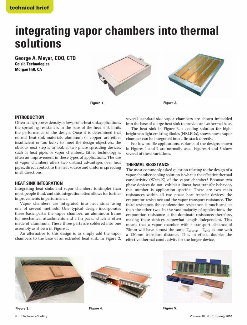
several standard-size vapor chambers are shown imbedded into the base of a large heat sink to provide an isothermal base.
The heat sink in Figure 3, a cooling solution for high-brightness light emitting diodes (HBLEDs), shows how a vapor chamber can be integrated into a fin stack directly.
For low profile applications, variants of the designs shown in Figures 1 and 2 are normally used. Figures 4 and 5 show several of these variations.
THERMAL RESISTANCEThe most commonly asked question relating to the design of a vapor chamber cooling solution is what is the effective thermal conductivity (W/m-K) of the vapor chamber? Because two phase devices do not exhibit a linear heat transfer behavior, this number is application specific. There are two main resistances within all two phase heat transfer devices: the evaporator resistance and the vapor transport resistance. The third resistance, the condensation resistance, is much smaller than the other two. In the vast majority of applications, the evaporation resistance is the dominate resistance; therefore, making these devices somewhat length independent. This means that a vapor chamber with a transport distance of 75mm will have almost the same Tsource - Tsink as one with a 150mm transport distance. This, in effect, doubles the effective thermal conductivity for the longer device.
INTRODUCTIONOften in high power density or low profile heat sink applications, the spreading resistances in the base of the heat sink limits the performance of the design. Once it is determined that normal heat sink materials, aluminum or copper, are either insufficient or too bulky to meet the design objectives, the obvious next step is to look at two phase spreading devices, such as heat pipes or vapor chambers. Either technology is often an improvement in these types of applications. The use of vapor chambers offers two distinct advantages over heat pipes, direct contact to the heat source and uniform spreading in all directions.
HEAT SINK INTEGRATIONIntegrating heat sinks and vapor chambers is simpler than most people think and this integration often allows for further improvements in performance.
Vapor chambers are integrated into heat sinks using one of several methods. One typical design incorporates three basic parts: the vapor chamber, an aluminum frame for mechanical attachments and a fin pack, which is often made of aluminum. These three parts are soldered into one assembly as shown in Figure 1.
An alternative to this design is to simply add the vapor chambers to the base of an extruded heat sink. In Figure 2,
integrating vapor chambers into thermal solutions
Figure 1. Figure 2.
Figure 4. Figure 3. Figure 5.
George A. Meyer, COO, CTO Celsia Technologies Morgan Hill, CA
technical brief
electronics-cooling.com ElectronicsCooling 5
Figure 8. Figure 9.
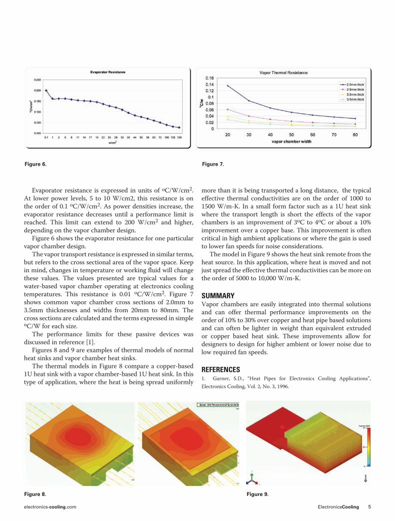
Evaporator resistance is expressed in units of oC/W/cm2. At lower power levels, 5 to 10 W/cm2, this resistance is on the order of 0.1 oC/W/cm2. As power densities increase, the evaporator resistance decreases until a performance limit is reached. This limit can extend to 200 W/cm2 and higher, depending on the vapor chamber design.
Figure 6 shows the evaporator resistance for one particular vapor chamber design.
The vapor transport resistance is expressed in similar terms, but refers to the cross sectional area of the vapor space. Keep in mind, changes in temperature or working fluid will change these values. The values presented are typical values for a water-based vapor chamber operating at electronics cooling temperatures. This resistance is 0.01 oC/W/cm2. Figure 7 shows common vapor chamber cross sections of 2.0mm to 3.5mm thicknesses and widths from 20mm to 80mm. The cross sections are calculated and the terms expressed in simple oC/W for each size.
The performance limits for these passive devices was discussed in reference [1].
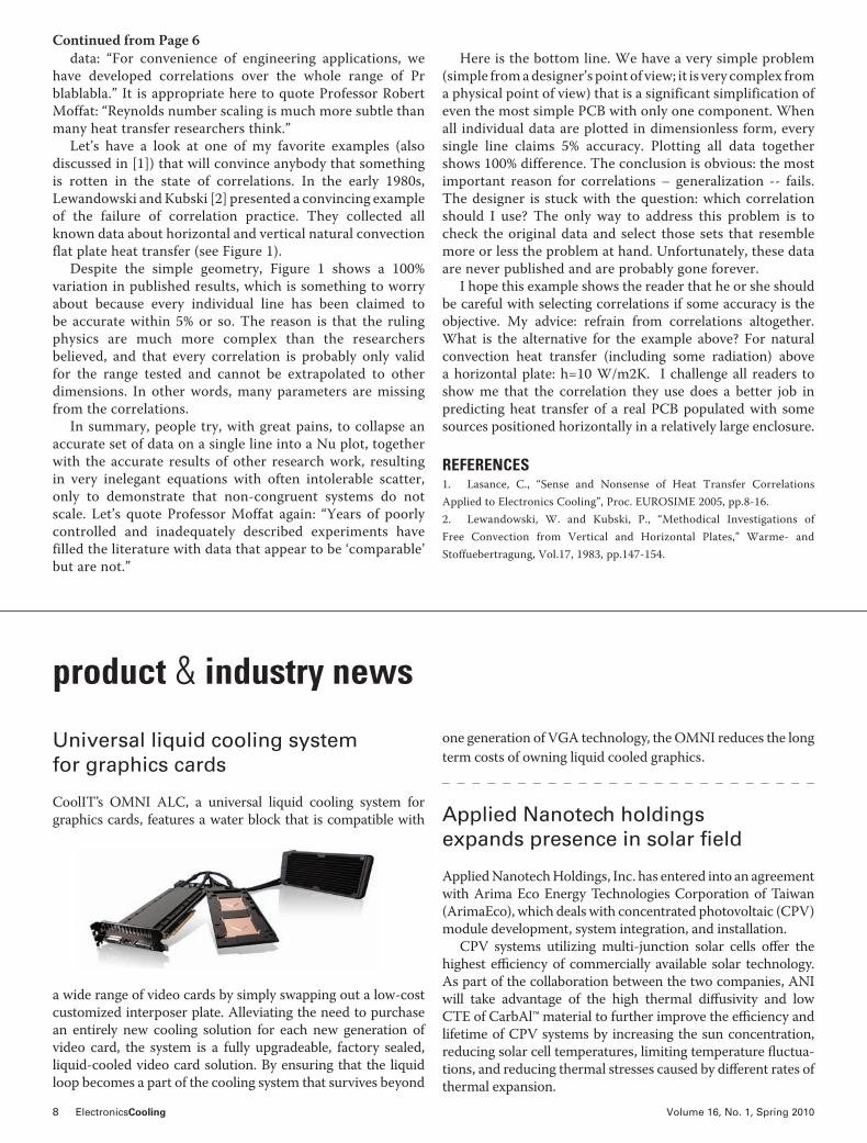
Figures 8 and 9 are examples of thermal models of normal heat sinks and vapor chamber heat sinks.
The thermal models in Figure 8 compare a copper-based 1U heat sink with a vapor chamber-based 1U heat sink. In this type of application, where the heat is being spread uniformly
Figure 6. Figure 7.
more than it is being transported a long distance, the typical effective thermal conductivities are on the order of 1000 to 1500 W/m-K. In a small form factor such as a 1U heat sink where the transport length is short the effects of the vapor chambers is an improvement of 3oC to 4oC or about a 10% improvement over a copper base. This improvement is often critical in high ambient applications or where the gain is used to lower fan speeds for noise considerations.
The model in Figure 9 shows the heat sink remote from the heat source. In this application, where heat is moved and not just spread the effective thermal conductivities can be more on the order of 5000 to 10,000 W/m-K.
SUMMARYVapor chambers are easily integrated into thermal solutions and can offer thermal performance improvements on the order of 10% to 30% over copper and heat pipe based solutions and can often be lighter in weight than equivalent extruded or copper based heat sink. These improvements allow for designers to design for higher ambient or lower noise due to low required fan speeds.
REFERENCES1. Garner, S.D., “Heat Pipes for Electronics Cooling Applications”, Electronics Cooling, Vol. 2, No. 3, 1996.

6 ElectronicsCooling Volume 16, No. 1, Spring 2010
reproducible experiments in research-type wind tunnels, resulting in accurate data linking, e.g., the heat transfer coefficient h to an average velocity v. Unfortunately, many professors demand that the following step is to make the variables dimensionless (e.g., rewrite h as Nu and v as Re) and plot Nu vs. Re on double-log paper, the rationale being that correlations are useful because they generalize the
Having read myriad papers/articles/books/reports on thermal management, I feel there is a lot of misunderstanding about what really should drive a sound approach of how to tackle the thermal problems that tend to land on the desk of thermal designers. I also have the feeling that many “how to” articles presented on the Web are just meant to show off the knowledge of the author and are full of correlations and equations, often emphasizing the dependence on temperature and consequently recommending iteration in one way or another.
The topic of this issue (and many to follow) is discussing the strange fact that many mechanical engineers with a firm background in heat transfer don’t seem to realize that the equations/correlations/formulae they use on a daily basis are derived in a completely different environment than the one they are trying to address. Obviously, understanding the physics of heat transfer requires boundary and initial conditions that are reproducible. Many PhDs have spent four years of their lives in performing repeatable and
thermal facts and fairy tales most of us live neither in wind tunnels nor in the world of Nusselt
Clemens J.M. Lasance, Associate EditorPhilips Research Laboratories Emeritus
Figure 1. Natural convection horizontal plate correlations.
product & industry news
Ultra-thick pad conforms to gap variances with quick shape rebound
!e Bergquist Company announces the addition of ultra-thick Gap Pad 1500S30 to its S-Class gap filling material line. Gap Pad 1500S30, now available in thicknesses of 160, 200 and 250 mil, maintains a conformable, highly elastic nature. !e material provides interfacing and wet-out characteris-tics, even to surfaces with the most uneven topography.
Gap Pad 1500S30 is fiberglass-reinforced, silicone-based, soft and compliant, rendering it an ideal material for de-creasing strain on frag-ile component leads and solder balls.
Gap Pad 1500S30 features an embedded-fiberglass reinforce-
ment for puncture, shear and tear resistance. Dual-sided tack eliminates the need for additional adhesive layers that typically inhibit thermal performance by increasing in-terfacial resistance. Natural tack properties also provide stable release characteristics for clean and easy handling during assembly. Typical applications for Gap Pad 1500S30 include computers and peripherals, power conversion, tele-communications and between any heat-generating semicon-ductor and a heat sink.
Constant conductance heat pipes provide thermal management for satellite
Advanced Cooling Technologies, Inc.’s Constant Conduc-tance Heat Pipes (CCHP) have been successfully operating in a commercial satellite on-orbit for more than 2,400 hours combined, the company recently announced. !e CCHPs are providing thermal management on-board the satellite which was launched on Nov. 30.
Continued on Page 8

electronics-cooling.com ElectronicsCooling 7
Highlights40 technical sessions, including 4 poster sessions
16 CEU-approved professional development courses
Technology Corner Exhibits, featuring approximately 70 industry-leading vendors
Emerging Technology Sessions, including Bioelectronics, Organic/Printable Electronics, and Green Packaging
Panel Discussion – The Emergence of the Medical Devices Industry through the View-glass of Microelectronic Packaging Innovation
CPMT Seminar – Advanced Bump and Bumpless Interconnection Technologies
Plenary Session – The Evolution of Mobile Processing Architectures
Special Tuesday Session – RFID and RFID-enabled Sensors: Packaging, Reliability, and Integration
Advanced Packaging Modeling & Simulation Optoelectronics Interconnections Materials & Processing
Applied Reliability Assembly & Manufacturing
Technology Electronic Components & RF Emerging Technologies
More than 300 technical papers covering:
Conference Sponsors:
8 ElectronicsCooling Volume 16, No. 1, Spring 2010
data: “For convenience of engineering applications, we have developed correlations over the whole range of Pr blablabla.” It is appropriate here to quote Professor Robert Moffat: “Reynolds number scaling is much more subtle than many heat transfer researchers think.”
Let’s have a look at one of my favorite examples (also discussed in [1]) that will convince anybody that something is rotten in the state of correlations. In the early 1980s, Lewandowski and Kubski [2] presented a convincing example of the failure of correlation practice. They collected all known data about horizontal and vertical natural convection flat plate heat transfer (see Figure 1).
Despite the simple geometry, Figure 1 shows a 100% variation in published results, which is something to worry about because every individual line has been claimed to be accurate within 5% or so. The reason is that the ruling physics are much more complex than the researchers believed, and that every correlation is probably only valid for the range tested and cannot be extrapolated to other dimensions. In other words, many parameters are missing from the correlations.
In summary, people try, with great pains, to collapse an accurate set of data on a single line into a Nu plot, together with the accurate results of other research work, resulting in very inelegant equations with often intolerable scatter, only to demonstrate that non-congruent systems do not scale. Let’s quote Professor Moffat again: “Years of poorly controlled and inadequately described experiments have filled the literature with data that appear to be ‘comparable’ but are not.”
Here is the bottom line. We have a very simple problem (simple from a designer’s point of view; it is very complex from a physical point of view) that is a significant simplification of even the most simple PCB with only one component. When all individual data are plotted in dimensionless form, every single line claims 5% accuracy. Plotting all data together shows 100% difference. The conclusion is obvious: the most important reason for correlations – generalization -- fails. The designer is stuck with the question: which correlation should I use? The only way to address this problem is to check the original data and select those sets that resemble more or less the problem at hand. Unfortunately, these data are never published and are probably gone forever.
I hope this example shows the reader that he or she should be careful with selecting correlations if some accuracy is the objective. My advice: refrain from correlations altogether. What is the alternative for the example above? For natural convection heat transfer (including some radiation) above a horizontal plate: h=10 W/m2K. I challenge all readers to show me that the correlation they use does a better job in predicting heat transfer of a real PCB populated with some sources positioned horizontally in a relatively large enclosure.
REFERENCES1. Lasance, C., “Sense and Nonsense of Heat Transfer Correlations Applied to Electronics Cooling”, Proc. EUROSIME 2005, pp.8-16.2. Lewandowski, W. and Kubski, P., “Methodical Investigations of Free Convection from Vertical and Horizontal Plates,” Warme- and Stoffuebertragung, Vol.17, 1983, pp.147-154.
product & industry news
Universal liquid cooling system for graphics cards
CoolIT’s OMNI ALC, a universal liquid cooling system for graphics cards, features a water block that is compatible with
a wide range of video cards by simply swapping out a low-cost customized interposer plate. Alleviating the need to purchase an entirely new cooling solution for each new generation of video card, the system is a fully upgradeable, factory sealed, liquid-cooled video card solution. By ensuring that the liquid loop becomes a part of the cooling system that survives beyond
one generation of VGA technology, the OMNI reduces the long term costs of owning liquid cooled graphics.
Applied Nanotech holdings expands presence in solar fi eld
Applied Nanotech Holdings, Inc. has entered into an agreement with Arima Eco Energy Technologies Corporation of Taiwan (ArimaEco), which deals with concentrated photovoltaic (CPV) module development, system integration, and installation.
CPV systems utilizing multi-junction solar cells o" er the highest e# ciency of commercially available solar technology. As part of the collaboration between the two companies, ANI will take advantage of the high thermal di" usivity and low CTE of CarbAl™ material to further improve the e# ciency and lifetime of CPV systems by increasing the sun concentration, reducing solar cell temperatures, limiting temperature fl uctua-tions, and reducing thermal stresses caused by di" erent rates of thermal expansion.
Continued from Page 6
electronics-cooling.com ElectronicsCooling 9
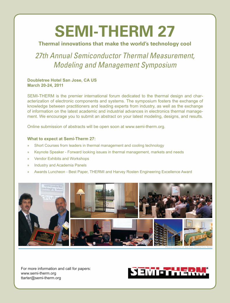
Doubletree Hotel San Jose, CA US
March 20-24, 2011
SEMI-THERM is the premier international forum dedicated to the thermal design and char-acterization of electronic components and systems. The symposium fosters the exchange of knowledge between practitioners and leading experts from industry, as well as the exchange of information on the latest academic and industrial advances in electronics thermal manage-ment. We encourage you to submit an abstract on your latest modeling, designs, and results. Online submission of abstracts will be open soon at www.semi-therm.org. What to expect at Semi-Therm 27:
» Short Courses from leaders in thermal management and cooling technology
» Keynote Speaker - Forward looking issues in thermal management, markets and needs
» Vendor Exhibits and Workshops
» Industry and Academia Panels
» Awards Luncheon - Best Paper, THERMI and Harvey Rosten Engineering Excellence Award
SEMI-THERM 27Thermal innovations that make the world’s technology cool
27th Annual Semiconductor Thermal Measurement,Modeling and Management Symposium
For more information and call for papers:www.semi-therm.orgttarter@semi-therm.org
Photos courtesy of San Jose DoubleTree Hotel
10 ElectronicsCooling Volume 16, No. 1, Spring 2010
INTRODUCTIONBecause of substantial increases in the power density of electronic packages over the past few decades, thermal interface resistance can comprise more than 50% of the total thermal resistance in current high-power packages [1]. Unless advanced thermal interface materials (TIMs) that achieve order-of-magnitude improvements in performance quickly emerge in the market, the portion of the thermal budget spent on interface resistance will continue to grow because die-level power dissipation densities are projected to exceed 1 W/mm2 (100 W/cm2) within the next 10 years [2]. Fortunately, improved understanding of heat transfer at nanometer scales, combined with increased ability to design new materials at the atomic level, has enabled a broad range of technological advances that can be applied to develop TIMs with performance characteristics that keep pace with cooling demands as electronics continue to evolve along Moore’s law.
Carbon nanotubes (CNTs) are honeycomb-like (i.e., hexagonally shaped) arrangements of carbon atoms that are rolled into cylindrical tubes with diameters as small as a few atoms wide and aspect ratios as high as 105. Because of these unique structural features and strong carbon-to-carbon bonding, CNTs possess many exceptional vibrational, optical, mechanical, and thermal properties that have been utilized in myriad applications. CNTs can be produced from a wide variety of processes, such as arc-discharge, pyrolysis of hydrocarbons over metal nanoparticles (e.g., in Chemical Vapor Deposition (CVD) or plasma-enhanced CVD processes), and laser vaporization of graphite targets, to name a few prominent methods.
Considerable attention has been focused on developing advanced TIMs that utilize the extraordinarily high axial thermal conductivity of CNTs – theoretical predictions suggest values as high as 3000 W/mK [3] and 6600 W/mK [4] for individual multiwalled CNTs and single-wall CNTs, respectively. Early studies focused on dispersing CNTs in a compliant polymer matrix to enhance the effective thermal conductivity of the composite structures [5]. Yet,
carbon nanotubes as high performance thermal interface materials
Baratunde A. ColaGeorgia Institute of Technology
Baratunde A. Cola is an assistant
professor in the George W. Woodruff
School of Mechanical Engineering at
the Georgia Institute of Technology. He
received his B.E (2002) and M.S. (2004)
from Vanderbilt University and his Ph.D.
(2008) from Purdue University, all in
mechanical engineering. At Purdue, he
was honored with an Intel Foundation
Fellowship, a Purdue Doctoral
Fellowship, and a NASA Institute
of Nanoelectronics and Computing
Fellowship. He was also the recipient of
the Purdue College of Engineering’s “Top
Dissertation Award” for his research
on photoacoustic characterization
of carbon nanotube array thermal
interfaces. Dr. Cola began at Georgia
Tech in April 2009 and has recently been
distinguished as a DARPA Young Faculty
Award recipient. His current research is
focused on fabricating and exploring the
properties of nanostructured surfaces
and interfaces to enhanced energy
transport and conversion, improve heat
transfer characteristics, and enable
microelectromechanical systems (MEMS)
and nanotechnology devices. The
NEST Lab develops new science and
technology exploiting energy transport
processes at the nanoscale.
electronics-cooling.com ElectronicsCooling 11
only modest improvements in thermal performance were achieved because enhancement of thermal conductivity in such structures is hindered by thermal interface resistance between CNTs and the matrix and mechanical stress at CNT-matrix boundaries that reduces the speed at which phonons propagate in the CNTs (i.e., the surrounding elastic medium alters phonon dispersion and reduces the intrinsic thermal conductivity in CNTs) [6]. While limited in comparison to dry CNT TIM structures as discussed below, CNT-polymer composites remain an active research focus and several companies are developing products based on this technology as highlighted in a recent article [7].
Over the past five years, significant attention has shifted to vertically oriented CNT arrays (a.k.a. CNT forest, mats, or films) as promising TIM structures that have been demonstrated to produce contact resistances that compare favorably to state-of-the-art materials [8]. Such configurations possess a synergistic combination of high mechanical compliance and high effective thermal conductivity — in the range of 10-200 W/mK [9-11]. The conformability feature is particularly advantageous in addressing mismatches in coefficients of thermal expansion that can cause TIM delamination and device failure. Also, in contrast to polymer-CNT composites and the best thermal greases, CNT array interfaces are dry and chemically stable in air from cryogenic to high temperatures (~ 450°C), making them suitable for extreme-environment applications [12].
It is important to note that all CNT array TIMs are not created equal; as a result, performance can vary greatly and depends on many factors, e.g., array density and height, CNT diameter, CNT quality, the adhesion of CNTs to the growth substrate, etc. However, since the first investigations of the efficacy of CNT arrays as TIMs, substantial improvements in metrology and synthesis control have led to lower thermal resistances and less scatter in reported values. The purpose of this article is to present and discuss recently published data on the performance of various CNT array TIMs that produce resistances that are near or below the range of resistances achieved by the best materials used today. The article highlights important characteristics, current performance bottlenecks, and significant technical considerations for integrating CNT array TIMs with real devices.
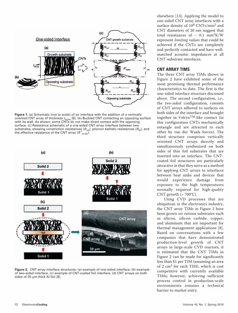
HEAT TRANSFER THROUGH CNT ARRAY INTERFACESThe most actively studied CNT array interface structure is the one-sided CNT array interface that consists of CNTs directly grown on one substrate with CNT free ends in contact with an opposing substrate (see Figure 1). The numerous CNT contacts at both substrates form parallel heat flow paths within the framework of the thermal resistance network illustrated in Figure 1. This network shows thermal resistances resolved at the individual nanotube level for true CNT-substrate interfaces, both at the growth substrate (with a nanotube number density of N, in contacts/area) and at the opposing interface (with a contacting nanotube number density of n). The resistance at each local CNT-substrate contact can be modeled as two resistances in series [13]: 1) a classical substrate constriction resistance (Rcs) and
2) a resistance (Rb) that results from the ballistic nature of phonon transport through contacts much smaller than the phonon mean free path in the materials (~ 100 nm). The ballistic resistance (Rb) is usually orders of magnitude larger than Rcs for CNT-substrate contacts, which are typically on the order of 10 nm. The remaining resistance (R”array) is from heat conduction through the CNT array. This effective resistance is defined for the entire array (including void spaces) to simplify the modeling effort. Moreover, this quantity has been measured in prior work for representative samples and can be used to interpret experimental results that only measure overall thermal interface resistance. When array height is less than 50 m, R”array is usually negligible in comparison to the resistances at the CNT-substrate contacts [13]. Given knowledge of the contact number densities at the growth substrate (N) and the opposing substrate (n), an overall or total interface resistance can be calculated. The former density (N) can be estimated from scanning electron micrographs of synthesized arrays, and the latter density (n) can be estimated using a recent model that predicts real contact area in CNT array interfaces as a function of applied pressure and important array characteristics, such as porosity and CNT diameter [13]. The model reveals that fabricating arrays with low effective compressive modulus is critical for establishing large interfacial contact and minimizing total thermal resistance. A detailed development of the CNT array TIM resistor network model is presented
12 ElectronicsCooling Volume 16, No. 1, Spring 2010
elsewhere [13]. Applying the model to one-sided CNT array interfaces with a surface density of 108 CNTs/mm2 and CNT diameters of 20 nm suggest that total resistances of ~ 0.1 mm2K/W represent limiting values that could be achieved if the CNTs are completely and perfectly contacted and have well-matched acoustic impedances at all CNT-substrate interfaces.
CNT ARRAY TIMSThe three CNT array TIMs shown in Figure 2 have exhibited some of the most promising thermal performance characteristics to date. The first is the one-sided interface structure discussed above. The second configuration, i.e., the two-sided configuration, consists of CNT arrays adhered to surfaces on both sides of the interface and brought together in VelcroTM-like contact (in this configuration CNTs mechanically entangle and are attracted to each other by van der Waals forces). The third structure comprises vertically oriented CNT arrays directly and simultaneously synthesized on both sides of thin foil substrates that are inserted into an interface. The CNT-coated foil structures are particularly attractive in that they serve as a method for applying CNT arrays to interfaces between heat sinks and devices that would experience damage from exposure to the high temperatures normally required for high-quality CNT growth (> 700°C). Using CVD processes that are ubiquitous in the electronics industry, the CNT array TIMs in Figure 2 have been grown on various substrates such as silicon, silicon carbide, copper, and aluminum that are important for thermal management applications [8]. Based on conversations with a few companies that have demonstrated production-level growth of CNT arrays in large-scale CVD reactors, it is estimated that the CNT TIMs in Figure 2 can be made for significantly less than $1 per TIM (assuming an area of 2 cm2 for each TIM), which is cost competitive with currently available TIMs; however, achieving sufficient process control in production-scale environments remains a technical barrier to market entry.
Figure 1. (a) Schematic (not to scale) of an interface with the addition of a vertically oriented CNT array of thickness tarray [8]. (b) Buckled CNT contacting an opposing surface with its wall. As shown, some CNTs do not make direct contact with the opposing surface. (c) Resistance schematic of a one-sided CNT array interface between two substrates, showing constriction resistances (Rcsi), phonon ballistic resistances (Rbi), and the effective resistance of the CNT array (R”array).
Figure 2. CNT array interface structures: (a) example of one-sided interface; (b) example of two-sided interface, (c) example of CNT-coated foil interface, (d) CNT arrays on both sides of 25 µm-thick Al foil [8].
Figure 2. CNT array interface structures: (a) example one-sided interface; (b) example two-sided interface, (c) example CNT-coated foil interface, (d) CNT arrays on both sides of 25 µm-thick Al foil [8].
electronics-cooling.com ElectronicsCooling 13
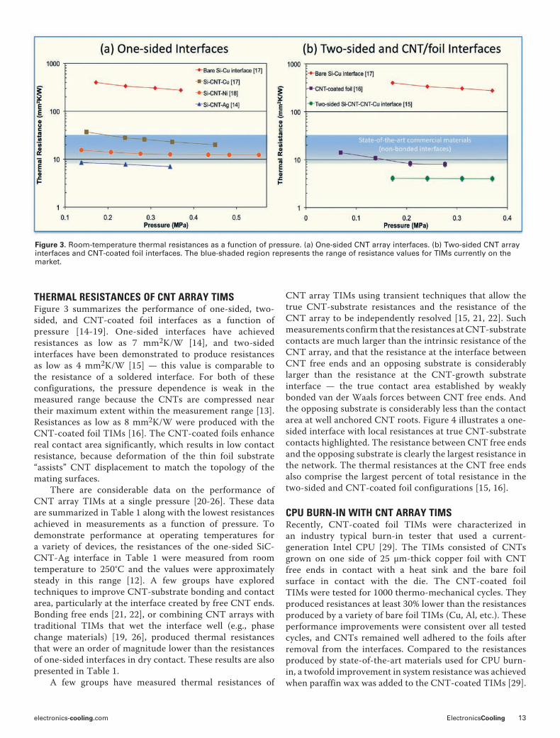
THERMAL RESISTANCES OF CNT ARRAY TIMSFigure 3 summarizes the performance of one-sided, two-sided, and CNT-coated foil interfaces as a function of pressure [14-19]. One-sided interfaces have achieved resistances as low as 7 mm2K/W [14], and two-sided interfaces have been demonstrated to produce resistances as low as 4 mm2K/W [15] — this value is comparable to the resistance of a soldered interface. For both of these configurations, the pressure dependence is weak in the measured range because the CNTs are compressed near their maximum extent within the measurement range [13]. Resistances as low as 8 mm2K/W were produced with the CNT-coated foil TIMs [16]. The CNT-coated foils enhance real contact area significantly, which results in low contact resistance, because deformation of the thin foil substrate “assists” CNT displacement to match the topology of the mating surfaces. There are considerable data on the performance of CNT array TIMs at a single pressure [20-26]. These data are summarized in Table 1 along with the lowest resistances achieved in measurements as a function of pressure. To demonstrate performance at operating temperatures for a variety of devices, the resistances of the one-sided SiC-CNT-Ag interface in Table 1 were measured from room temperature to 250°C and the values were approximately steady in this range [12]. A few groups have explored techniques to improve CNT-substrate bonding and contact area, particularly at the interface created by free CNT ends. Bonding free ends [21, 22], or combining CNT arrays with traditional TIMs that wet the interface well (e.g., phase change materials) [19, 26], produced thermal resistances that were an order of magnitude lower than the resistances of one-sided interfaces in dry contact. These results are also presented in Table 1. A few groups have measured thermal resistances of
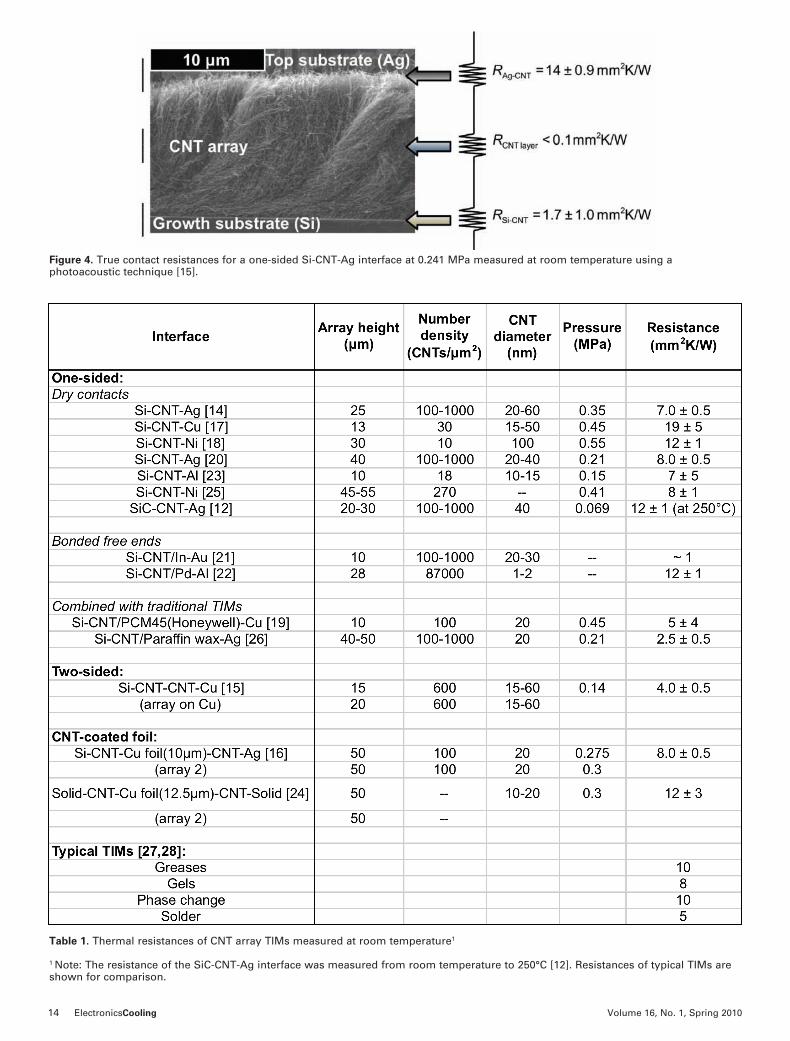
CNT array TIMs using transient techniques that allow the true CNT-substrate resistances and the resistance of the CNT array to be independently resolved [15, 21, 22]. Such measurements confirm that the resistances at CNT-substrate contacts are much larger than the intrinsic resistance of the CNT array, and that the resistance at the interface between CNT free ends and an opposing substrate is considerably larger than the resistance at the CNT-growth substrate interface — the true contact area established by weakly bonded van der Waals forces between CNT free ends. And the opposing substrate is considerably less than the contact area at well anchored CNT roots. Figure 4 illustrates a one-sided interface with local resistances at true CNT-substrate contacts highlighted. The resistance between CNT free ends and the opposing substrate is clearly the largest resistance in the network. The thermal resistances at the CNT free ends also comprise the largest percent of total resistance in the two-sided and CNT-coated foil configurations [15, 16].
CPU BURN-IN WITH CNT ARRAY TIMSRecently, CNT-coated foil TIMs were characterized in an industry typical burn-in tester that used a current-generation Intel CPU [29]. The TIMs consisted of CNTs grown on one side of 25 $m-thick copper foil with CNT free ends in contact with a heat sink and the bare foil surface in contact with the die. The CNT-coated foil TIMs were tested for 1000 thermo-mechanical cycles. They produced resistances at least 30% lower than the resistances produced by a variety of bare foil TIMs (Cu, Al, etc.). These performance improvements were consistent over all tested cycles, and CNTs remained well adhered to the foils after removal from the interfaces. Compared to the resistances produced by state-of-the-art materials used for CPU burn-in, a twofold improvement in system resistance was achieved when paraffin wax was added to the CNT-coated TIMs [29].
Figure 3. Room-temperature thermal resistances as a function of pressure. (a) One-sided CNT array interfaces. (b) Two-sided CNT array interfaces and CNT-coated foil interfaces. The blue-shaded region represents the range of resistance values for TIMs currently on the market.
14 ElectronicsCooling Volume 16, No. 1, Spring 2010
Table 1. Thermal resistances of CNT array TIMs measured at room temperature1
1 Note: The resistance of the SiC-CNT-Ag interface was measured from room temperature to 250°C [12]. Resistances of typical TIMs are shown for comparison.
Figure 4. True contact resistances for a one-sided Si-CNT-Ag interface at 0.241 MPa measured at room temperature using a photoacoustic technique [15].

electronics-cooling.com ElectronicsCooling 15
CONCLUSIONSTo date, three CNT array TIM configurations have been developed to the point where they produce resistances that compare favorably to the best TIMs currently in use. So far, the lowest resistances produced by CNT array TIMs are on the order of 1 mm2K/W. Further improvements can be achieved by optimizing the compliance of CNT arrays to maximize the real contact area in the interface. Experimental data and theoretical predictions reveal that the resistances at CNT-substrate contacts severely limit the potential of CNT array TIMs. Improvements in bonding and thermal transport at these contacts can lead to substantial reductions in resistance, approaching estimated theoretical limits of ~ 0.1 mm2K/W.
REFERENCES1. Prasher, R., “Thermal Interface Materials: Historical Perspective, Status, and Future Directions,” Proceedings of IEEE, Vol. 94, 2006, pp. 1571-1586.2. International Roadmap for Semiconductors (2007), Assembly and Packaging, http://www.itrs.net/Links/2007ITRS/Home2007.htm3. Che, J.W., Cagin, T., Goddard, W.A., “Thermal Conductivity of Carbon Nanotubes,” Nanotechnology, Vol. 11, 2000, pp. 65-69.4. Berber, S., Kwon, Y.K., Tomanek, D., “Unusually High Thermal Conductivity of Carbon Nanotubes,” Physical Review Letters, Vol. 84, 2000, pp. 4613-4617.5. Biercuk, M.J., Llaguno, M.C., Radosavljevic, M., Hyun, J.K., Johnson, A.T., Fischer, J.E., “Carbon Nanotube Composites for Thermal Management,” Applied Physics Letters, Vol. 80, 2002, pp. 2767-2769. 6. Prasher, R., “Thermal Conductance of Single-Walled Carbon Nanotube Embedded in an Elastic Half-Space,” Applied Physics Letters, Vol. 90, 2007, p. 143110.7. Lasance, C.J.M., “Thermal Conductivity of Filled Plastics,” Electronics Cooling Magazine, Vol. 15, No. 2, 2009. 8. Cola, B.A., Fisher, T.S., Xu, X., “Carbon Nanotube Array Thermal Interfaces,” Chapter in Carbon Nanotubes: New Research, Ed. A.P. Ottenhouse, Nova Science Publishers, 2009, pp. 101-118. 9. Hu, J.X., Padilla, A.A., Xu, J., Fisher, T.S., Goodson, K.E., “3-Omega Measurements of Vertically Oriented Carbon Nanotubes on Silicon,” ASME Journal of Heat Transfer, Vol. 128, 2006, pp. 1109-1113.10. Yang, D.J., Zhang, Q., Chen, G., Yoon, S.F., Ahn, J., Wang, S.G., Zhou, Q., Wang, Q., and Li, J.Q., “Thermal Conductivity of Multiwalled Carbon Nanotubes,” Physical Review B, Vol. 66, 2002, p. 165440.11. Hone, J., Llaguno, M.C., Nemes, N.M., Johnson, A.T., Fischer, J.E., Walters, D.A., Casavant, M.J., Schmidt, J., and Smalley, R.E., “Electrical and Thermal Transport Properties of Magnetically Aligned Single Wall Carbon Nanotube Films,” Applied Physics Letters, Vol. 77, 2000, pp. 666.12. Cola, B.A., Capano, M.A., Amama, P.B., Xu, X., Fisher, T.S., “Carbon Nanotube Array Thermal Interfaces for High-temperature Silicon Carbide Devices,” Nanoscale and Microscale Thermophysical Engineering, Vol. 12(3), 2008, pp. 228.13. Cola, B.A., Xu, J., Fisher, T.S, “Contact Mechanics and Thermal Conductance of Carbon Nanotube Array Interfaces,” International Journal of Heat and Mass Transfer, Vol. 52, 2009, pp. 3490.14. Cola, B.A., Amama, P.B., Xu, X., Fisher, T.S., “Effects of Growth Temperature on Carbon Nanotube Array Thermal Interfaces,” ASME Journal of Heat Transfer, Vol. 130, 2008, p. 114503.15. Cola, B.A., Xu, J., Cheng, C., Xu, X., Hu, H., Fisher, T.S., “Photoacoustic Characterization of Carbon Nanotube Array Thermal Interfaces,” Journal
of Applied Physics, Vol. 101, 2007, p. 054313.16. Cola, B.A., Xu, X., Fisher, T.S., “Increased Real Contact in Thermal Interfaces: A Carbon Nanotube/Foil Material,” Applied Physics Letters, Vol. 90, 2007, p. 093513.17. Xu, J., Fisher, T.S., “Enhanced Thermal Contact Conductance Using Carbon Nanotube Array Interfaces,” IEEE Transactions on Components and Packaging Technology, Vol. 29, 2006, pp. 261-267.18. Xu, Y., Zhang, Y., Suhir, E., Wang, X., “Thermal Properties of Carbon Nanotube Array Used for Integrated Circuit Cooling,” Journal of Applied Physics, Vol. 100, 2006, p. 074302.19. Xu, J., Fisher, T.S., “Enhancement of Thermal Interface Materials with Carbon Nanotube Arrays,” International Journal of Heat and Mass Transfer, Vol. 49, 2006, pp. 1658-1666.20. Amama, P.B., Cola, B.A., Sands, T.D., Xu, X., Fisher, T.S., “Dendrimer-assisted Controlled Growth of Carbon Nanotubes for Enhanced Thermal Interface Conductance,” Nanotechnology, Vol. 18, 2007, p. 385303.21. Tong, T., Zhao, Y., Delzeit, L., Kashani, A., Meyyappan, M., Majumdar, A., “Dense Vertically Aligned Multiwalled Carbon Nanotube Arrays as Thermal Interface Materials,” IEEE Transactions on Components and Packaging Technology, Vol. 30, 2007, pp. 92- 99.22. Panzer, M., Zhang, G., Mann, D., Hu, X., Pop, E., Dai, H., Goodson, K.E., “Thermal Properties of Metal-Coated Vertically Aligned Single-Wall Nanotube Arrays,” ASME Journal of Heat Transfer, Vol. 130, 2008, p. 052401. 23. Zhang, K., Chai, Y., Yuen, M.M.F., Xiao, D.G.W., Chan, P.C.H., “Carbon Nanotube Thermal Interface Material for High-Brightness Light-Emitting-Diode Cooling,” Nanotechnology, Vol. 19, 2008, p. 215706. 24. Wang, H., Feng, J., Hu, X., and Ng, K.M, “Synthesis of Aligned Carbon Nanotubes on Double-Sided Metallic Substrates by Chemical Vapor Deposition,” Journal of Physical Chemistry C, Vol. 111, 2007, pp. 12617-12624.25. Liu, X., Zhang, Y., Cassell, A.M., and Cruden, B.A., “Implications of Catalyst Control for Carbon Nanotube Based Thermal Interface Materials,” Journal of Applied Physics, Vol. 104, 2008, p. 084310.26. Cola, B.A., Hodson, S.L., Xu, X., and Fisher, T.S., “Carbon Nanotube Array Thermal Interfaces Enhanced with Paraffin Wax,” Proceedings of 2008 ASME Summer Heat Transfer Conference, Jacksonville, FL, 2008.27. Prasher, R., “Thermal Interface Materials: Historical Perspective, Status, and Future Directions,” Proceedings of the IEEE, Vol. 94, No. 8, 2006, pp. 1571-1586.28. Chung, D.D.L., “Materials for Thermal Conduction,” Applied Thermal Engineering, Vol. 21, 2001, pp. 1593-1605.29. Cola, B.A., “Photoacoustic Characterization and Optimization of Carbon Nanotube Array Thermal Interfaces,” Ph.D. Dissertation, Purdue University, West Lafayette, IN, 2008.
B!"!#$%&' A. C()! can be reached at [email protected] or 404-385-8652.
www.electronics-cooling.com
Whatever the needs of a particular application, you’ll find a wide choice of manufacturers and sources of valuable information in the electronics-cooling.com Buyer’s Guide section. Just log on to www.electronics-cooling.com, click on Buyer’s Guide, and make your selection.
More on the Web
16 ElectronicsCooling Volume 16, No. 1, Spring 2010
INTRODUCTIONBy 2008 the electronics content of a typical consumer vehicle had grown to 20-25% of the total vehicle cost [1]. This content provides a wide range of functions and features for today’s driver. Some features such as the radio/audio system and instrument cluster are quite familiar and visible to the driver and have been mainstays in the automobile for many years. Other functions such as engine controllers and body computers (passenger comfort and convenience feature control) are less visible to the driver but are vital to the operation of the vehicle.
The need for high reliability in the harsh automotive environment demands robust and capable cooling designs. These cooling systems need to be manufactured for the very high volume automotive market (> 60 million vehicles per year) at a low cost and with high quality. In addition to being environmentally friendly and recyclable, automotive electronic products also require maintenance-free operation during their greater than 10-year lifetime.
The automotive electronics market is characterized by a wide range of vehicle types with varied functional content. Each of these vehicle types (motorcycles, light-duty cars or trucks, heavy duty on and off-road trucks, and construction or agricultural equipment) has a different range of environmental and operational requirements.
There is also a wide range of electronic applications within each of these vehicle types including but not limited to: powertrain and emission controllers; vehicle body, antitheft, and comfort controllers; communication, navigation, display and entertainment systems; vehicle braking, traction/stability, steering, low tire warning, collision warning and airbag systems. Three product areas are currently seeing significant product proliferation: electric powertrain control for hybrid and electric vehicles, passenger and vehicle safety systems, and driver connectivity, including anti-distraction systems.
POWER DISSIPATION CHALLENGES AND DESIGN APPROACHESMost applications have waste power dissipation that ranges from milliwatts to 100 watts. However, waste heat for
electronics cooling in the automotive environment
Bruce A. Myers, Gary Eesley, David IhmsDelphi Electronics & Safety
Bruce A. Myers is a Principal Technical
Fellow at Delphi Electronics & Safety
in Kokomo, Ind. He holds a bachelor’s
and master’s degree in physics from
Ball State University and has 32 years
of experience in automotive electronics
testing, packaging and cooling. Bruce
has been issued 34 U.S. patents in
the area of electronics packaging
and has a number of publications and
presentations in this technical area. He
has extensive experience in hybrid-‐ and
laminate-‐based electronic products, flip
chip technology, and electronics cooling.
He is a member of the Delphi Innovation
Hall of Fame.
Gary Eesley is a Technical Fellow at
Delphi Electronics working in Advanced
Power Electronics and Advanced
Power/Thermal Packaging groups.
His current activities include thermal
characterization of materials and
advanced thermal packaging. Previously,
he was a Sr. Staff Scientist at Delphi
Research Labs, following his tenure as a
staff member in the Physics Department
at General Motors Research, where
he established a laser laboratory with
emphasis on ultra fast time-‐resolved
studies of thermal transport in materials.
He received a Ph.D.EE degree from the
University of Southern California.
David Ihms is a Senior Project Engineer
with Delphi Electronics & Safety in
Kokomo, Ind. He has been with the
company for over 20 years, the first
13 working in advanced displays and
alternate lighting and the last 7 years
in advanced assembly and packaging,
where he specializes in adhesives and
underfills. He has held memberships
in the SMTA, SAE, iMAPS and NEMI
professional organizations. He has seven
patents, is a recipient of numerous
internal recognition awards, and a LEAD
award for “alternate cleaning chemistry
and process development.” He has a
doctorate in organic chemistry.

18 ElectronicsCooling Volume 16, No. 1, Spring 2010
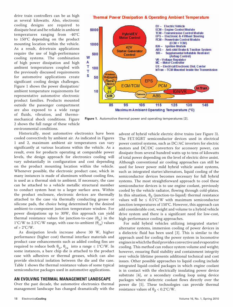
drive train controllers can be as high as several kilowatts. Also, electronic cooling designs are required to dissipate heat and be reliable in ambient temperatures ranging from -40°C to 150°C depending on the product mounting location within the vehicle. As a result, drivetrain applications require the use of high-performance cooling systems. The combination of high power dissipation and high ambient temperatures coupled with the previously discussed requirements for automotive applications create significant cooling design challenges. Figure 1 shows the power dissipation/ambient temperature requirements for representative automotive electronic product families. Products mounted outside the passenger compartment are also exposed to a wide range of fluids, vibration, and thermo-mechanical shock conditions. Figure 2 shows the full range of these vehicle environmental conditions.
Historically, most automotive electronics have been cooled convectively by ambient air. As indicated in Figures 1 and 2, maximum ambient air temperatures can vary significantly at various locations within the vehicle. As a result, even for products operating at comparable power levels, the design approach for electronics cooling will vary substantially in configuration and cost depending on the product mounting location within the vehicle. Whenever possible, the electronic product case, which in many instances is made of aluminum without cooling fins, is used as a thermal sink to ambient. If necessary, the case can be attached to a vehicle metallic structural member to conduct system heat to a larger surface area. Within the product enclosure, electronic devices are thermally attached to the case via thermally conducting grease or silicone pads, the choice being determined by the desired ambient-to-component junction temperature window. For power dissipations up to 30W, this approach can yield thermal resistance values for junction-to-case (%jc) in the 1°C/W to 2.5°C/W range, with case-to-ambient (%ca) values of > 2°C/W.
As dissipation levels increase above 30 W, higher performance (higher cost) thermal interface materials and product case enhancements such as added cooling fins are required to reduce both %jc, %ca into a range & 1°C/W. In some instances, a bare chip die is attached to the product case with adhesives or thermal greases, which can also provide electrical isolation between the die and the case. Table 1 shows the thermal resistance values of some typical semiconductor packages used in automotive applications.
AN EVOLVING THERMAL MANAGEMENT LANDSCAPEOver the past decade, the automotive electronics thermal management landscape has changed dramatically with the
advent of hybrid vehicle electric drive trains (see Figure 3). The FET/IGBT semiconductor devices used in electrical power control systems, such as DC/AC inverters for electric motors and DC/DC converters for accessory power, can dissipate from several hundred watts up to tens of kilowatts of total power depending on the level of electric drive assist. Although conventional air cooling approaches can still be used for lower power mild hybrid vehicle assist systems, such as integrated starter/alternators, liquid cooling of the semiconductor devices becomes necessary for full hybrid systems. The most straightforward approach to cool these semiconductor devices is to use engine coolant, previously cooled by the vehicle radiator, flowing through cold-plates. In this situation, %jl (junction-to-liquid) thermal resistance values will be & 0.5°C/W with maximum semiconductor junction temperatures of 150°C. However, this approach can add considerable cost, weight and volume to a hybrid vehicle drive system and there is a significant need for low-cost, high-performance cooling approaches.
For mild hybrid vehicles utilizing integrated starter/alternator systems, immersion cooling of power devices in a dielectric fluid has been used [3]. This is similar to the approach used for cooling the power system in locomotive engines in which the fluid provides convective and evaporative cooling. This method can reduce system volume and weight; however, ensuring fluid stability and containment integrity over vehicle lifetime presents additional technical and cost issues. Other possible approaches to liquid cooling include integrated liquid-cooled packages in which engine coolant is in contact with the electrically insulating power device substrate [4], or a secondary cooling loop using device packages where dielectric coolant flows directly over the power die [5]. These technologies can provide thermal resistance values of %jl < 0.2°C/W.
Figure 1. Automotive thermal power and operating temperatures [2].

electronics-cooling.com ElectronicsCooling 19
Many other components also require cooling. Bus capacitors and inductors can be effectively cooled by thermal conduction to the product case. The system battery pack can be cooled by forced-air convection through an appropriately designed package enclosure utilizing either ambient or passenger compartment air. In addition to air and liquid cooling technology, new developments in heat pipe/thermosiphon and thermoelectric cooling technology are being monitored.
CHOOSING SUITABLE TECHNOLOGIES AND MATERIALS FOR COOLING STRUCTURESJust as crucial as the method of cooling are the materials used in cooling structures. Not only do they contribute to the thermal “stackup” resistance, packaging materials are also responsible for maintaining device integrity in a very demanding thermal environment. With power densities ranging from <1 W/cm2 to 400 W/cm2, the thermal management landscape in automotive electronics is very diverse. This requires a comprehensive approach for the selection of cooling technology, materials, and manufacturing processes.
A wide spectrum of compatible materials (metals, semi-conductors, ceramics, plastics, composites and possibly dielectric fluids) are required for robust automotive thermal cooling systems. Many unusual materials with specific properties are required to provide critical performance functions including thermal conduction, insulation, fluid transport, surface passivation, bonding and sealing, structural support or low friction interfaces. Careful selection of these materials on the basis of cost, performance, stability and mutual compatibility requires a detailed understanding of their thermal, mechanical and chemical characteristics.
The key high-reliability require- ments for operating temperatures spanning -40°C to 150°C are thermal performance and stability. Composite and polymeric materials must neither be brittle nor exhibit excessive thermal softening. A careful selection of material thermal expansion coefficient differences must be made to control possible bulk mechanical fatigue, fracture or delamination of electrical interconnect structures and bonded surfaces. The material combinations selected must also accommodate thermal shock caused by power spikes which can reach 30°C/sec ramp rates on or near silicon devices.
Similar to thermal creep and expansion is the concern for mechanical wear-out of seals and diaphragms at their interfaces. Thorough knowledge of material and function specifications coupled with experimental performance data can establish proper part geometries and the optimal material set for the
required product life.Thermal interface materials (TIMs) improve the thermal
pathway at the interface of dissimilar materials by mitigating the effects of surface irregularities and air gaps. A variety of TIMs are available, such as semi-liquids, (thermal greases) and solid-state materials (pre-formed pads and curable TIMs) for this purpose. When using TIMs, potential areas of concern are mechanical pump-out of greases, dry-out of the continuous phase, and micro-structure fracturing.
When compared to radiation and conduction, liquid cooling offers improved thermal performance. The most common automotive cooling fluids are water-based. Water-based cooling fluids provide excellent thermal properties but also introduce significant design hurdles. Aqueous systems are notorious for promoting ionic corrosion. Additives and co-solvents address this concern and also provide freezing point depression and boiling point elevation while operating under pressures approaching 400 kPa (60 psi). However, high pressure and high flow rates in these fluid systems can cause mechanical wear of cooling system components.
In the future cooling systems may use heat transport fluids that come into direct contact with silicon power die. These high dielectric constant fluids (fluorocarbons) are not flammable and can be used in low pressure systems even under two-phase operation, but only provide a fraction of the heat transport capability of water-based systems. Chemical activity of these materials can be very low, but fluorine-based molecules pose significant compatibility issues with flexible tubing and many other halogen-based materials.
Therefore, it is important to use materials in the cooling system that have little to no interaction with these fluids. Plasticizers and oligomers can be leached from flexible
Figure 2. Summary of the automotive electronics environment [2].

20 ElectronicsCooling Volume 16, No. 1, Spring 2010
tubing or halogen-based seal materials and then deposited onto critical heating surfaces by the working fluid. Even low level absorption (~5%) of the fluids can cause material swelling, which indicates softening of the barrier material, dimensional change, and increased permeation of gases through the barrier. Dielectric fluids can absorb significant amounts of gases, especially carbon dioxide, which will evolve when the fluid is heated. Rapid de-aeration of the fluid will compromise the heat transport efficiency. Triboelectric materials in contact with a fast flowing dielectric fluid can also be an electrostatic discharge (ESD) generation concern.
Conductive and semi-conductive materials (solids) may be used to control this ESD generation. Table 2 summarizes many of the cooling system material selection concerns.
CONCLUSIONMost cooling system compatibility issues are those germane to the interior of the system. Externally, dust, debris and automotive fluids can foul heat exchanger surfaces and reduce heat transport efficiency.
Automotive electronic products are required to be reliable and maintenance-free in harsh operating environments for
Figure 3. Electronics content of hybrid electric vehicle.
Semiconductor
Package Type
Std. 208 Leaded QFP on a PCB
256 Leaded BGA on a PCB
TO-220 Transis-tor with Electrical
Isolation
Flip Chip with Top of Chip Heat Sinking
Custom High Power Transistor
Package
Thermal
Resistance
30-50 °C/W (j-a)
30-40 °C/W (j-a)
1-2°C/W(j-c)
0.5-1.0°C cm2/W
(j-c)
<1°C cm2/W
(j-c)
Materials and
ConcernsThermal Mechanical Stability
Fluid
CompatibilityOther Environment
Metals Thermal Resistance Fatigue
Oxidation/Corro-sion with Aqueous
SystemsMass
Thermal Interface Materials
Thermal Resistance
Cracking, Pump-out Dry-out Leaching Cost
Electrical Interconnects Fatigue
Silicon Brittle, Low CTE
Insulators/Plastics Fatigue Brittle or Too Soft
Leaching or Swell-ing
Adhesives/ Bonding
Thermal Resistance
Delamination, Cracking
Epoxy Very Good, Silicones Poor Heat Cure
Elastomers/Seals Mechanical Wear Swelling Cost Leakage
Table 1. Typical Semiconductor Thermal Resistance (°C/W) or Unit Thermal Resistance (°C cm2/W) Values
Table 2. Summary of Cooling System Material Issues

electronics-cooling.com ElectronicsCooling 21
Thermal circuit breaker series offers rotary knob actuator
Schurter’s TA35 thermal circuit breaker series now o"ers a rotary style actuator. In addition to the classic rocker style, the grip and turn style knob is well-suited for applications where a longer feedback is desired, such as those where gloves are used. !e new TA35 ro-tary switch o"er IP 40 protection. !e switch and thermal overload protec-tion with positively trip-free release includes current ratings ranging from 0.05 A to 20 A for 1- and 2- pole types, and 0.05 A to 12 A for the 3-pole ver-sion. Admissable ambient tempera-ture range is from -30ºC to +60 ºC.
Data center cooling solutions cut energy consumption and costs
Coolcentric™, a new division of Vette Corp.®, o"ers pat-ented LiquiCool® technology in a variety of turnkey data center cooling system solutions that can reduce cooling unit energy consumption by up to 90 percent and lower total data center cooling costs by as much as 60 percent. !ese liquid cool-ing systems include Rear Door Heat Ex-changers (RDHx) that mount to the back of IT racks and cool computer equipment ex-haust air before it reenters the data center operating environment. !e open cooling ar-chitecture allows deployment with-out any operational impact to IT racks or equipment and is suitable for both raised- and non-raised-floor data centers.
periods exceeding 10 years. However, these products also have to be produced in high volumes and at low cost. Some applications, such as hybrid vehicle drivetrain electronics, require liquid-cooling systems that can dissipate power levels exceeding 1 kW. The combination of these requirements is unique when compared to other consumer, commercial and aerospace electronic products. As a result, the design of the cooling systems required for automotive electronic applications demands careful technology development as well as long term material reliability and compatibility evaluations to ensure robust and reliable operation.
REFERENCES1. “Electronics Penetration Has Leveled”, The Hansen Report on Automotive Electronics, Nov. 2006, Vol. 19, No.9, pg. 1.2. Myers, B.A., “Cooling Issues for Automotive Electronics,” ElectronicsCooling, Vol. 9, No. 3, August, 2003, pp. 30-34.3. Miller, J.M., “Propulsion Systems for Hybrid Vehicles,” Inst. Engineering Tech., 2004, p. 58.4. O’Keefe, M., Bennion, K., “Comparison of Hybrid Vehicle Power Electronics Cooling Options,” Paper NREL/CP-540-41886, January 2008.5. Sung, M.K., Muduwar, I., “CHF Determination for High-Heat Flux Phase Change Cooling System Incorporating Both Micro-Channel Flow and Jet Impingement”, Intl. Journal of Heat and Mass Transfer 52, (2009), pp. 610-619.
Contact B"$*' A. M+'", at [email protected], G!"+ E',)'+ at [email protected] and D!-.& I/0, at [email protected].
product & industry news
www.electronics-cooling.com
Look for more information on thermal management in the automotive industry on the Automotive Channel at www.electronics-cooling.com/category/industries/automotive.
Or, check out other industry-related news, including: Aerospace Defense Communications Industrial Computer IT Products Consumer Lighting Data Centers Medical Power
More on the Web

22 ElectronicsCooling Volume 16, No. 1, Spring 2010
INTRODUCTIONSmall-channel heat sinks provide an extremely compact and efficient vehicle for dissipation of large heat fluxes typically found in high power electronics. Fluid flow and heat transfer in small-sized channels, with hydraulic diameters on the order of a fraction of a millimeter (a few hundred micrometers), have been shown to behave similarly to conventional-sized channels (hydraulic diameter of many millimeters) for single phase liquid flow. Many studies have established that the classical behavior, as predicted by Navier-Stokes equations, remains valid for small channels [1-3] for single phase liquid flow. However, a departure in small channel two-phase flowbehavior has been observed from that of conventional-sized channels. A significant amount of work has been dedicated to measuring and predicting the heat transfer behavior in small-channel heat sinks for two-phase flow [6-14]. Each flow configuration, single-phase or two-phase flow, comes with its unique advantages and challenges. This article presents a case study to outline the advantages and challenges, and presents a systematic methodology for the calculation of fluid flow and heat transfer parameters for each flow configuration for small-channel heat sinks.
THEORY AND MODELINGSINGLE PHASE FLOWThe physics of single-phase flow and heat transfer is well understood and has been substantiated over the years. It has been shown conclusively in the literature that it remains applicable to channels that are much smaller in diameter than the conventional channels encountered in typical coldplate applications. For single-phase laminar liquid flow in small channels, the frictional pressure drop for hydrodynamically developed flow can be expressed as follows:
(1)
Where the friction factor fsp can be expressed as [4],
a case study to demonstrate the trade-offs between liquid and two-phase cooling schemes for small-channel heat sinks in high heat flux applicationsAnurag Gupta, David H. Altman, Stephen J. PereiraRaytheon Integrated Defense Systems
David H. Altman is a Principal Engineer
and Program Manager in Raytheon
Integrated Defense Systems Advanced
Technology Programs Directorate.
His work focuses on research and
development into thermal management
technologies for next generation defense
electronics. His current interests include
development of micro and nanomaterial
heat spreading thermal and thermal
interface technologies, as well as phase
change cooling. David holds BS and MS
degrees from Rensselaer Polytechnic
Institute and Boston University.
Stephen J. Pereira, P.E., an Engineering
Fellow and Section Manager working in
the Mechanical Systems Department in
Sudbury, Mass., has been with Raytheon
Company since 1980. He received his
B.S.M.E. in 1980 from the University
of Rhode Island, and his M.S.M.E. from
Northeastern University in 1985. He has
29 years of experience in thermal design
and analysis, from system-‐level cooling
of phased array radars to the evaluation
of thermal performance for GaN and
GaAs MMIC devices.
Anurag Gupta is a senior engineer in the
Mechanical Engineering Department of
Raytheon Integrated Defense Systems.
His work at Raytheon is dedicated to
the development of thermal solutions
for very high heat flux applications. The
main areas of his career focus have been
thermal design and analysis of electronic
systems, ground vehicle aerodynamics,
and structural design of defense systems.
Anurag received his bachelor’s degree
from Indian Institute of Technology in
1992, and master’s degree from Rutgers
University in 1995.
electronics-cooling.com ElectronicsCooling 23
(2)
The Nusselt number for thermally fully developed laminar flow in a channel heated on three sides is given as [5]:
(3)
Equations (1) to (3) complete the definition required to calculate the pressure drop and heat transfer coefficient for fully developed single-phase flow in small channels.
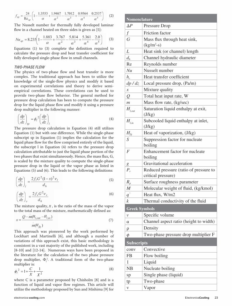
TWO-PHASE FLOWThe physics of two-phase flow and heat transfer is more complex. The traditional approach has been to utilize the knowledge of the single-flow physics and modify it based on experimental correlations and theory to derive semi-empirical correlations. These correlations can be used to provide two-phase flow behavior. The general method for pressure drop calculation has been to compute the pressure drop for the liquid phase flow and modify it using a pressure drop multiplier in the following manner:
(4)
The pressure drop calculation in Equation (4) still utilizes Equation (1) but with one difference. While the single-phase subscript sp in Equation (1) implies the calculation for the liquid phase flow for the flow comprised entirely of the liquid, the subscript l in Equation (4) refers to the pressure drop calculation attributable to just the liquid phase portion of the two phases that exist simultaneously. Hence, the mass flux, G, is scaled by the mixture quality to compute the single-phase pressure drop in the liquid or the vapor phase as listed in Equations (5) and (6). This leads to the following definitions:
(5)
(6)
The mixture quality, x , is the ratio of the mass of the vapor to the total mass of the mixture, mathematically defined as:
(7)
This approach was pioneered by the work performed by Lockhart and Martinelli [6], and although a number of variations of this approach exist, this basic methodology is consistent in a vast majority of the published work, including [8-10] and [12-14]. Numerous ways have been proposed in the literature for the calculation of the two phase pressure drop multiplier, 'l
2. A traditional form of the two-phase multiplier is:
22 11
XXC
l (8)
where C is a parameter proposed by Chisholm [8] and is a function of liquid and vapor flow regimes. This article will utilize the methodology proposed by Sun and Mishima [9] for
NomenclatureP Pressure Drop
ƒ Friction factor
G
2-s)
L
dh
Re
Nu
hc
dp / dz
x
Q
m
Hl,out
Hl,in
Hfg
S
F
g
Pr
Rp
M
q”
k
Greek Symbolsv
()!Subscriptsconv Convective
FB
1
NB
sp
tp
v Vapor
H H
H

24 ElectronicsCooling Volume 16, No. 1, Spring 2010
the determination of the two-phase pressure drop multiplier. They proposed a new form of the Chisholm parameter, C, for laminar flow and showed it to fit a large amount of experimental data from various studies:
(9)
The Laplace number, La, is a measure of the surface tension and buoyancy effects:
(10)
Also, X, the Martinelli parameter is a ratio of the liquid phase pressure drop to the vapor phase pressure drop as follows [6]:
(11)
which makes the Martinelli parameter, X, a known parameter for a given flow condition. Equations [4-11] complete the definition for pressure drop in two-phase flow.
The prediction of heat transfer in two-phase flow is challenging because of the simultaneous existence of the liquid and vapor phase convective heat transfer as well as the boiling heat transfer. Several approaches exist — some that rely mostly on boiling heat transfer and many others that consider the effect of convective as well as boiling heat transfer. One particular approach that accounts for both effects, and will be demonstrated in this article, is of the form [7]:
(12)
where S is a suppression factor for the nucleate boiling term as additional liquid is converted to vapor during the boiling process and F is the enhancement factor to account for the
increased rate of convective heat transfer as flow velocities increase due to the larger specific volume of the vapor phase. Several ways have been proposed in the literature for the calculation of the suppression and enhancement factors, S and F, and the heat transfer coefficients related to nucleate boiling and two-phase convection. This article will demonstrate the one proposed by Bertsch, Groll, and Garimella [10] for the determination of the heat transfer parameters, including the suppression and enhancement factors and heat transfer coefficients.
References [9] and [10] were chosen for pressure drop and heat transfer calculations, respectively, since they are recent and have compared their methodology against a comprehensive database of experimental and empirical predictive work. It should be noted that since two-phase flow is not well understood, any particular set of correlations from a published study may be prone to errors under certain conditions. Consequently, reliance on any one particular study is not recommended; however, a detailed examination of any single study reveals the underlying physics. The knowledge acquired, however, can be used to formulate the analysis methodology for a real application.
Bertsch et al [10] proposed employing Cooper’s [11] pool boiling correlation for the nucleate boiling term, hNB, given as:
(13)
For the convective term, hconv,tp, they proposed the following:
(14)
In other words, the contribution to the convective two phase flow was proportioned between the liquid phase, hc,conv,l, and the vapor phase, hc,conv,v, in proportion to the mixture quality level, x. Hausen’s correlation [15] was suggested for the determination of liquid and vapor phase heat transfer
Figure 1. Small channel heat sink cooling configuration for this case study.

electronics-cooling.com ElectronicsCooling 25
coefficients. The proposed suppression factor, S, is (1-x), while the resulting enhancement factor, F, was derived from fitting a curve to a large database as: [1+80(x2 —x6)e-0.6La]. This resulted in the heat transfer coefficient for the two-phase flow of the form [10]:
(15)
Equations (1) to (15) complete the definition of single-phase (liquid) and two-phase pressure drop and heat transfer for the purpose of this article. Their application is being demonstrated in the next section.
A REPRESENTATIVE APPLICATION OF LIQUID AND TWO-PHASE COOLINGA small heat sink, 1cm wide and 5 cm long, was chosen for illustration purposes. The configuration of the heat sink and the microchannels is shown in Figure 1. The choice of this particular configuration was motivated by published studies by Mudawar et al [12, 13] for which the experimental data is also available. The heat sink had 20 machined channels that are each 750 µm tall and 250 µm wide. The top of the channels were insulated, which resulted in three-sided heating of the channel. Fin efficiency calculations showed that these fins were approximately 90% efficient at the design conditions for both the liquid and the two-phase flow. As expected, due to the lower heat transfer coefficient, single-phase flow resulted in slightly higher fin efficiency. For simplicity in the analysis, the fin efficiency was held constant at 90%. Water was used as the working fluid for this demonstration. An inlet temperature of 30oC was used for both the single and two-phase cooling. All analysis was conducted for a heat sink base heat flux of 100 W/cm2. The analysis parameters are shown in Table 1.
SINGLE PHASE PRESSURE LOSS AND HEAT TRANSFEREquations (1) and (2) were used to determine the pressure drop in the heat sink shown in Figure 1 for the parameters shown in Table 1. A mass flux of 1150 kg/m2-s (or 4.3e-3 kg/s) was chosen to maintain the liquid in single phase at the exit of the heat sink. Fluid properties were calculated at the mean of the inlet and the outlet temperature.
Calculations show that the flow is laminar with a Reynolds number of 675. It is hydrodynamically developed and thermally developing at the heat sink exit. A frictional pressure loss of 9520 Pa (or 1.38 psi) was computed using Equations (1) and (2). In addition to the frictional pressure loss, the other mechanisms that result in pressure loss are due to acceleration, contraction, and expansion. Accelerational pressure loss is due to an increase in the liquid specific volume as its temperature rises along the channel length. It was negligible for this case study. Contraction pressure loss results from the fluid being funneled into the heat sink from a larger opening at the entrance. The entrance region was assumed to be the same size as the total heat sink cross-sectional area, 1 cm wide by 750 µm high. This resulted in a flow contraction ratio of 0.5, i.e. half the flow volume was occupied by the fin walls in the heat sink volumetric space. This contraction pressure drop loss computed to be
about 1200 Pa (or 0.17 psi). The final term is the pressure recovery at the exit when the liquid expands from a smaller volume (channels) into the exit manifold. The pressure recovery was computed to be 423 Pa (or 0.06 psi). The reader is encouraged to refer to [14] for more information on contraction pressure losses and expansion recovery.
(16)Hence, the total pressure loss was computed to be 10297 Pa (or 1.49 psi), with approximately 92% associated with the frictional pressure loss. Equation (3), for 3-sided heating of a channel, was used to determine the Nusselt number for the liquid flow. The computed average Nusselt number for the channel was 5.82, resulting in a heat transfer coefficient, computed as hc=Nu k/dh, of 10090 W/m2-K. This heat transfer coefficient results in a heat sink base temperature rise of 31oC above the cooling liquid temperature. It should also be noted that there is considerable temperature gradient along the heat sink base, from the inlet to the exit due to the fluid heating along the length of the heat sink.
TWO- PHASE PRESSURE LOSS AND HEAT TRANSFERThis simulation was similar to the single-phase conditions except that the flow rate was reduced to ensure that a two-phase condition existed for a significant portion of the channel along the heat sink length. A mass flux was chosen which resulted in nearly the same pressure loss as the single-phase case, equal to approximately 10,000 Pa. A mass flux of 150 kg/m2-s (or 5.6e-4 kg/s) was used. This resulted in single
Table 1. Analysis parameters for this case study
Figure 2. Variation of heat transfer coefficient with quality
Inlet temperature °C 30Inlet pressure bar 1
W/m2 1.0E+06Total heat applied at heat sink base W 500Channel hydraulic diameter m 3.75E-04Channel aspect ratio 3
Bertsch, Groll and Garimella [10]

26 ElectronicsCooling Volume 16, No. 1, Spring 2010
phase liquid condition in one-third of the channel length, or 15.7 mm, and two-phase in the remaining two-thirds, or 34.3 mm. A set of inlet conditions and mass flow rate could be chosen to create two-phase conditions along the entire length of the channel, if so desired. The following contributions from the various pressure drop mechanisms were found by using equations (1-2) and (4-11) for pressure drop in single and two-phase flow:
Equation (15) predicts a heat transfer coefficient that is a function of mixture quality, or effectively, the position along the length of the channel as the mixture quality changes. The variation of heat transfer coefficient with quality is shown in Figure 2. Heat transfer coefficients ranging from 20,000 to 27,000 W/m2-K were achieved in the two phase region, which results in heat sink-to-fluid temperature differences between 11.6 and 15.6oC. The larger sink-to-fluid temperature difference occurs at the heat sink exit due to the degradation in heat transfer coefficient with increasing quality along the channel length.
A comparison of the heat sink performance for the single-phase and two-phase flow conditions is shown in Figure 3. The values plotted for two-phase flow are at the center of the channel. The plots in Figure 3 show that the average two-phase flow heat transfer coefficient of 23,000 W/m2-K is more than twice the single phase flow configuration (10090 W/m2-K), at a similar pressure drop of about 10,000 Pa (1.5 psi) for each configuration. Additionally, the enhanced heat transfer coefficient from two-phase flow results in a substantially lower wall-to-fluid temperature difference: an average of 13.6oC as compared to 31oC for single phase flow. One other key discriminator between the two cooling schemes is that the saturation state in two-phase flow will maintain a nearly constant fluid and heat sink wall temperature, versus single-phase flow where the fluid rises in temperature along the length of the heat sink.
CONCLUSIONSThis case study presents a systematic study of the calculation of, and tradeoffs between, single and two-phase cooling schemes. The pressure loss and heat transfer coefficients were compared for each cooling scheme. The data presented herein demonstrates that while single-phase and two-phase cooling are both viable options for cooling applications with high heat fluxes, two-phase cooling provides enhanced heat transfer at the same system pressure loss.
REFERENCES1. Liu, D., and Garimella, S.V., “Investigation of Liquid Flow
in Microchannels,” AIAA Journal of Thermophysics, Heat Transfer, 18, 2004, pp. 65-72.
2. Lee, P.S., Garimella, S.V., and Liu, D., “Investigation of Heat Transfer in Rectangular Microchannels,” International Journal of Heat and Mass Transfer, 48, 2005, pp. 1688-1704.
3. Judy, J., Maynes, D., and Webb, B.W., “Characterization of Frictional Pressure Drop for Liquid Flows Through Microchannels,” International Journal of Heat and Mass Transfer, 45, 2002, pp. 3477-3489.
4. Shah, R.K. and London, A.L., “Laminar Flow Forced Convection in Ducts,” Supplement 1 to Advances in Heat Transfer, New York: Academic Press, 1978.
5. Phillips, R.J., “Forced Convection, Liquid Cooled, Microchannel Heat Sinks,” MS Thesis, Massachusetts Institute of Technology, 1987.
6. Lockhart, R.W. and Martinelli, R.C., “Proposed Correlation of Data for Isothermal Two-Phase, Two Component Flow in Pipes,” Chemical Engineering Progress, 45, 1949, pp. 39-48.
7. Chen, J.C., “Correlation for Boiling Heat Transfer to Saturated Fluids in Convective Flow,” I&EC Process Design and Development, Vol. 5 (3), 1966, pp. 322-329.
8. Chisholm, D., “A Theoretical Basis for the Lockhart-Martinelli Correlation for Two-Phase Flow,” International Journal of Heat and Mass Transfer, 10 (12), 1967, pp. 1767-1778.
9. Sun, L. and Mishima, K., “Evaluation Analysis of Prediction Methods for Two-Phase Flow Pressure Drop
Figure 3. Comparison between single and two-phase flow (a) pressure drop in Pa, (b) heat transfer coefficient in W/m2-K, (c) Wall-to-fluid temperature drop in oC.
(a) (c)
electronics-cooling.com ElectronicsCooling 27
in Mini-Channels,” International Journal of Multiphase Flow, 35, 2009, pp. 47-54.
10. Bertsch, S.S., Groll, E.A., and Garimella, S.V., “A Composite Heat Transfer Correlation for Saturated Flow Boiling in Small Channels,” International Journal of Heat and Mass Transfer, 52, 2009, pp. 2110-2118.
11. Cooper, M.G., “Heat Flow Rates in Saturated Nucleate Pool Boiling – A Wide-Ranging Examination Using Reduced Properties,” Advances in Heat Transfer, V. 16, 1984, pp. 157-239.
12. Qu, W. and Mudawar, I., “Measurement and Prediction of Pressure Drop in Two-Phase Micro-Channel Heat Sinks,” International Journal of Heat and Mass Transfer, 46, 2003, pp. 2737-2753.
13. Qu, W. and Mudawar, I., “Flow Boiling Heat Transfer in Two-Phase Micro-Channel Heat Sinks – I. Experimental Investigation And Assessment of Correlation Methods,” International Journal of Heat and Mass Transfer, 46, 2003, pp. 2755-2771.
14. Collier, J.G. and Thome, J.R., “Convective Boiling and Condensation,” Third edition, Oxford University Press, Oxford, 1996, pp. 108-112.
15. Incropera, F.P. and Dewitt, D.P., “Fundamentals of Heat and Mass Transfer,” Fourth edition, John Wiley and Sons, 1996, pp. 443-444.
C ont a c t A % $ " !1 G $ 2 #! a t anurag.g upt a @ ray t he on .c om or 978-440-1470, D!-.& H. A)#0!% at [email protected] or 978-440-1585, and S#'2/'% J. P'"'."! at [email protected] or 978-440-3932.
product & industry newsHeat sinks offer secure attachment with minimum of board real estate
Alpha’s series of heat sinks feature an innovative attachment mechanism. Electronic components have become faster and more compact, generating more heat and increasing thermal densities. !is has led to the use of heat sinks of increased size and mass. One of the biggest challenges for thermal/mechanical engineers is mechanically mounting larger heat sinks while minimizing the amount board real estate used by the attachment mechanism. Generating su#cient attach-ment force is also critical with regard to mechanical security and proper performance of thermal interface materials. Al-pha’s Quick Set series heat sinks have been designed to ad-dress both issues, providing secure and reliable attachment while requiring the absolute minimum of board real estate.
Textbook covers basic heat transfer theory, practical guidelines
“Heat Transfer: !ermal Man-agement of Electronics,” a ref-erence and textbook by Dr. Younes Shabany, includes both basic heat transfer theory as well as practical guidelines for solving thermal design problems that are common to electronic products. Younes Shabany is with the Advanced Technology Group at Flextron-ics and also teaches at San Jose State University. !e book is available through CRC Press.
www.electronics-cooling.com
If this article piqued your interest in heat sinks, read more on the topic by visiting the Heat Sink Channel at www.electronics-cooling.com/category/applications/heat-sinks.
Also, peruse information on other Applications, including:
Blowers/Fans/Filters Ceramics Coolers Liquid Cooling Heat Pipes Plastics Semiconductor TIM TECs Test & Measurement Design SubstratesMaterials Compounds Adhesives
More on the Web
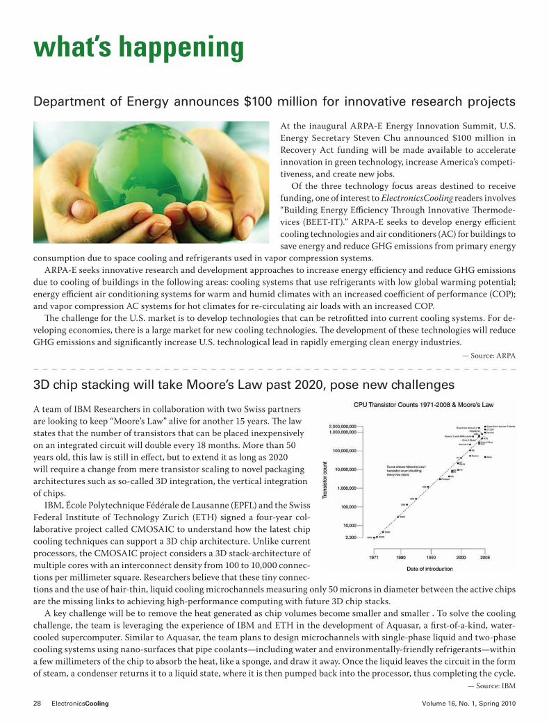
28 ElectronicsCooling Volume 16, No. 1, Spring 2010
Department of Energy announces $100 million for innovative research projects
At the inaugural ARPA-E Energy Innovation Summit, U.S. Energy Secretary Steven Chu announced $100 million in Recovery Act funding will be made available to accelerate innovation in green technology, increase America’s competi-tiveness, and create new jobs.
Of the three technology focus areas destined to receive funding, one of interest to ElectronicsCooling readers involves “Building Energy E#ciency !rough Innovative !ermode-vices (BEET-IT).” ARPA-E seeks to develop energy e#cient cooling technologies and air conditioners (AC) for buildings to save energy and reduce GHG emissions from primary energy
consumption due to space cooling and refrigerants used in vapor compression systems. ARPA-E seeks innovative research and development approaches to increase energy e#ciency and reduce GHG emissions
due to cooling of buildings in the following areas: cooling systems that use refrigerants with low global warming potential; energy e#cient air conditioning systems for warm and humid climates with an increased coe#cient of performance (COP); and vapor compression AC systems for hot climates for re-circulating air loads with an increased COP.
!e challenge for the U.S. market is to develop technologies that can be retrofitted into current cooling systems. For de-veloping economies, there is a large market for new cooling technologies. !e development of these technologies will reduce GHG emissions and significantly increase U.S. technological lead in rapidly emerging clean energy industries.
— Source: ARPA
3D chip stacking will take Moore’s Law past 2020, pose new challenges
A team of IBM Researchers in collaboration with two Swiss partners are looking to keep “Moore’s Law” alive for another 15 years. !e law states that the number of transistors that can be placed inexpensively on an integrated circuit will double every 18 months. More than 50 years old, this law is still in e"ect, but to extend it as long as 2020 will require a change from mere transistor scaling to novel packaging architectures such as so-called 3D integration, the vertical integration of chips.
IBM, École Polytechnique Fédérale de Lausanne (EPFL) and the Swiss Federal Institute of Technology Zurich (ETH) signed a four-year col-laborative project called CMOSAIC to understand how the latest chip cooling techniques can support a 3D chip architecture. Unlike current processors, the CMOSAIC project considers a 3D stack-architecture of multiple cores with an interconnect density from 100 to 10,000 connec-tions per millimeter square. Researchers believe that these tiny connec-tions and the use of hair-thin, liquid cooling microchannels measuring only 50 microns in diameter between the active chips are the missing links to achieving high-performance computing with future 3D chip stacks.
A key challenge will be to remove the heat generated as chip volumes become smaller and smaller . To solve the cooling challenge, the team is leveraging the experience of IBM and ETH in the development of Aquasar, a first-of-a-kind, water-cooled supercomputer. Similar to Aquasar, the team plans to design microchannels with single-phase liquid and two-phase cooling systems using nano-surfaces that pipe coolants—including water and environmentally-friendly refrigerants—within a few millimeters of the chip to absorb the heat, like a sponge, and draw it away. Once the liquid leaves the circuit in the form of steam, a condenser returns it to a liquid state, where it is then pumped back into the processor, thus completing the cycle.
— Source: IBM
what’s happening

Have you visited electronics-cooling.com lately?
We recently re-launched the site!
Visit www.electronics-cooling.com for the most up-to-date information on Thermal Management:Industry newsInformation sorted by industry and applicationNew product listingsBuyer’s Guide Archives of ElectronicsCooling magazinesIndustry event and symposium listingsAccess to free software trials On- demand webinarsA chance to follow ElectronicsCooling through our blogs and Twitter (e_cooling)And much more!
30 ElectronicsCooling Volume 16, No. 1, Spring 2010
EuroSimE 2010Thermal, Mechanical and Multiphysics Simulation and Experiments in Micro/Nanoelectronics and Systems
WHEN: April 26-28WHERE: Mercure Cité Mondiale, Bordeaux, FranceWHAT: An international conference dedicated to thermal, mechanical and multiphysics simulation and experiments in microelectronics and microsystems, EuroSimE was ini-tiated in 2000. !e 11th in the series, EuroSimE 2010 aims to promote further development and application of simu-lation methodologies and tools for the electronics indus-try; improve communication and exchange information between methodology & tool-developers and industry us-ers; and strengthen co-operation between industry, univer-sities, and research institutes. INFORMATION: www.eurosime.org/
International Conference on High Temperature Electronics (HiTEC 2010)
WHEN: May 11- 13WHERE: Hyatt Regency, Albuquerque, N.M. WHAT: HiTEC 2010 provides a comprehensive technical program addressing the applications, and the latest devel-opment in devices, circuits, MEMS, sensors, packaging, power sources, and materials to address the challenges of applications for high temperature electronics, includ-ing smart energy, underhood automotive, oil well logging, geothermal, more electric aircraft, space, industrial sen-sors, etc. Tabletop exhibits will complement the technical program by providing an opportunity to view the latest products for high temperature electronics. INFORMATION: www.imaps.org/hitec/
Uptime Institute Symposium 2010Data Center Efficiency & Green Enterprise IT
WHEN: May 17-19 WHERE: Hilton New York, New York CityWHAT: Focused on data center e#ciency and green enter-prise IT, the Uptime Institute Symposium attracts stake-holders in enterprise IT, finance, executive management, data center facilities, and corporate real estate to deal with the critical issues surrounding enterprise computing, re-
source and energy e#ciency, availability and productivity. !is year’s event will feature presentations, roundtables, panel discussions, and an exhibition hall with products aimed at improving energy and resource e#ciency in the data center and beyond.INFORMATION: http://symposium.uptimeinstitute.com/
Electronic Components and Technology Conference (ECTC)
WHEN: June 1-4WHERE: Paris Las Vegas, Las Vegas, Nev.WHAT: An international packaging, components, and mi-croelectronics systems technology conference, ECTC of-fers an array of packaging technology information. !is year’s conference will have 39 technical sessions, 16 profes-sional development courses, a panel discussion, a plenary session, a CPMT Seminar, and a technology corner for ex-hibitors. Technical program topics include advanced pack-aging, modeling and simulation, optoelectronics, intercon-nections, materials and processing, applied reliability and assembly and manufacturing technology.INFORMATION: www.ectc.net/
International Heat Transfer Conference (IHTC-14)WHEN: August 8-13WHERE: Omni Shoreham Hotel, Washington, D.C.WHAT: !is year marks the first time IHTC will be held in the United States since 1986. !e IHTC aims to provide a technical forum that includes keynote lectures, poster ses-sions, professional development courses, and a live exhibit. In addition to the fundamentals of thermal phenomena and traditional thermal applications, the IHTC is expected to address the emerging domains of thermal transport in nano-materials, bio-systems, Power Generation, MEMS, Microsystems, information systems, energy conversion devices, aerospace and hostile environment systems. INFORMATION: www.asmeconferences.org/IHTC14/
16th International Workshop on Thermal Investigations of ICs and Systems (THERMINIC)
WHEN: October 6-8WHERE: Novotel Barcelona City, Barcelona, Spain
[Diary Dates]Some important 2010 events in the electronic thermal management community. Visit us online at www.electronics-cooling.com for the latest listings.
electronics-cooling.com ElectronicsCooling 31
WHAT: THERMINIC Workshops are a series of events to discuss the essential thermal questions of microelectronic microstructures and electronic parts in general. !is year the workshop will address in addition to the “traditional” thermal management problems, also stress and thermal-stress-related-reliability issues, both in micro- and opto-electronics fields. !ese issues, including various nano-technology applications, are of significant importance and of high interest to the engineering community engaged in the field of thermal phenomena in “high-tech” systems. INFORMATION: http://cmp.imag.fr/conferences/thermin-ic/therminic2010/
Thermal Management & Technology SymposiumWHEN: October 19-20WHERE: Gaylord Texan, Dallas, TexasWHAT: !ermal Management and Technology Symposium highlights the latest advancements in thermal technol-ogy for product design, system development and process management. !is event will feature presentations on the latest advancements in thermal management and thermal technology for electronics packaging and cooling, thermal process control, temperature sensing and control, thermal materials, systems design and management for optimizing thermal properties. INFORMATION: www.thermalnews.com/conf_10/TN10_index.php
Materials Research Society (MRS) Fall MeetingMagneto Calorics and Magnetic Cooling
WHEN: November 29–December 3WHERE: Boston, Mass.WHAT: Consisting of topical symposia, the MRS meeting o"ers materials researchers the opportunity to present their work, get information on up-to-the minute develop-ments in their field, and network. In addition, the Materials Research Society has established the MRS Workshop Se-ries, which o"ers highly focused and compelling subjects, designed to allow full attention to one topic over a two to three day period. INFORMATION: www.mrs.org/meetings
PowerMEMS 2010The 10th International Workshop on Micro and Nano-technology for Power Generation and Energy Conver-sion Applications
WHEN: November 30–December 3WHERE: Leuven, BelgiumWHAT: Technical topics of interest include, energy harvest-ing for remote sensors and Microsystems; thermoelectric and photovoltaic materials and systems; piezoelectric, elec-trostatic and electromagnetic conversion; energy manage-ment and microsystem integration; nanostructured mate-rials for energy and thermal management; micro fuel cells and micro reactors for fuel processing; micro/nano cataly-sis, combustion, heat and mass transfer; micro thrusters and miniature propulsion Microsystems; and biologically inspired energy conversion and cooling.INFORMATION: www.powermems.org/
Third International Conference on Thermal Issues in Emerging Technologies Theory and Application - ThETA 3
WHEN: December 19-22WHERE: Sofitel El Gazirah, Cairo, EgyptWHAT: Emerging technologies in various domains, includ-ing Microelectronics, Nanotechnology, Smart Materials, Micro-Electro-Mechanical Systems, Biomedical Engineer-ing, and New Energies, all raise issues related to thermal e"ects and interactions. !eir importance is continuously increasing, tending to be a dominant factor in new tech-nologies. Topics will include micro and nano-scale heat transfer, microfluidics, thermal modeling of electronic systems, and temperature aware computer systems design, among others.INFORMATION: www.thetaconf.org/index.htm

32 ElectronicsCooling Volume 16, No. 1, Spring 2010
index of advertisers
Volume 15, Number 1.
February 2009
cooling electronics with nanofluids:
laminar convective heat transfer
mini- and microchannels in thermal
interfaces: spatial, temporal, material,
and practical significance
when Moore is less: exploring the 3rd
dimension in IC packaging
cooling electronics with nanofluids:
laminar convective heat transfer
mini- and microchannels in thermal
interfaces: spatial, temporal, material,
and practical significance
when Moore is less: exploring the 3rd
dimension in IC packaging
Volume 15, Number 1.
February 2009
Volume 16, Number 1Spring 2010
Carbon nanotubes as high performance thermal interface materials
Electronics cooling in the automotive environment
A case study to demonstrate the trade-offs between liquid and two-phase cooling schemes for small-channel heat sinks in high heat flux applications
electronics-cooling.com
Know anyone who should receive this magazine but didn’t?Let them know that ElectronicsCooling Magazine is back!
ALPHA NOVATECH, INC. INSIDE BACK COVER
BERGQUIST COMPANY INSIDE FRONT COVER
EBM PAPST BACK COVER
ECTC 2010 7
ELECTRONICS COOLING SOLUTIONS 31
ELECTRONICS-COOLING.COM 29
MALICO INC. 2
MENTOR GRAPHICS 17
SEMI-THERM 27 9
SUMMIT THERMAL SYSTEM CO., LTD. 11
Want to advertise in ElectronicsCooling? Contact: Paul Salotto, Publisher, ElectronicsCooling -
ITEM Publications, Philadelphia, PA, USA - (US) 484.688.0300 - [email protected]
ElectronicsCooling is published four times a year
March | June | September | December
Make sure they don’t miss out on
receiving the next edition.
Visit www.electronics-cooling.com
to subscribe NOW!


Unlock the Power!
Imagine that in the future, we suddenly offered one of our best compact fans with five times the motor output and nearly double the nominal speed. This fan would offer by far the highest air flow and the highest pressure of all products available in its size. At operating points with high counterpressure, it would provide outstanding cooling air flow and – as is typical for ebm-papst – exemplary motor efficiency and long service life. Now imagine that we have already done it. With an entire series. Unleash the beast and experience the S-Force, the premium class of high-performance compact fans. Learn more today at www.ebmpapst.us/sforce
The engineer’s choice


![Preparation of multiwall carbon nanotubes (MWCNTs ...€¦ · polymeric reinforcement[1–4].Theypossessoutstandingelec-trical, mechanical and thermal properties compared to conven-tional](https://static.fdocuments.in/doc/165x107/5f0d06527e708231d4384d8d/preparation-of-multiwall-carbon-nanotubes-mwcnts-polymeric-reinforcement1a4theypossessoutstandingelec-trical.jpg)