
Carbon Monoxide (CO) Analyzer - Automaatika · PDF filevarying boiler operating conditions ......
12
Product Data Sheet PDS 106-510A Model 5100A September, 1998 Visit our website at www.processanalytic.com On-line ordering now available. • Dual Microprocessor Based Exceptionally easy to operate Control room access to all analyzer functions Programmable operating parameters for varying boiler operating conditions • Control Room Diagnostic Capability Alerts operator to preventative maintenance requirements Eliminates costly unscheduled maintenance • Rugged, New Infrared Source Design Contains no focusing optics, eliminating vibration sensitivity and precise alignment procedures • Sturdy, Reliable Receiver Design 185°F(85°C) electronics, non-cooled detector assure stable performance at high ambient temperature NEMA 4X(IP56) enclosure for harsh industrial environments • Completely Automatic Zero/Span Calibration Assures continuously reliable data without operator intervention Internal standards eliminate need for external calibration devices • In Situ Analysis Representative across-duct measurement, free from stratification errors Eliminates sampling system maintenance The importance of controlling excess air levels in various combustion processes has been recognized for many years. Now, however, the high cost of fuel makes it an economic necessity to reduce excess air levels to minimize thermal stack losses. Efforts toward combustion efficiency optimization, however, must be aimed at reducing total energy loss. This requires achieving minimum unburned combustible, as well as thermal stack losses. More precise control of air/fuel ratio, optimized for minimum total energy loss, can yield significant gains in efficiency and result in substantial savings in reduced fuel consumption. Flue gas concentration of carbon monoxide is a reliable and accurate indication of burner flame stoichiometry and the completeness of combustion. It is the most sensitive indicator of unburned combustibles loss. Used as a primary combustion efficiency parameter, in conjunction with oxygen analysis, carbon monoxide offers significant advantages in controlling combustion at optimum levels of excess air. Controlling air/fuel ratio to an optimum level of carbon monoxide assures minimum total energy loss, and maximum efficiency, independent of variations in boiler load, fuel type and fuel quality. The measurement is relatively unaffected by air in-leakage, and burner maintenance requirements are immediately identified. Rosemount’s innovative new technology, coupled with small, lightweight packaging, and ease of operation and maintenance, assures you of years of trouble free service from the Model 5100A CO Analyzer. Carbon Monoxide (CO) Analyzer INTRODUCTION
-
Upload
nguyenquynh -
Category
Documents
-
view
218 -
download
1
Transcript of Carbon Monoxide (CO) Analyzer - Automaatika · PDF filevarying boiler operating conditions ......

Product Data SheetPDS 106-510AModel 5100A September, 1998
Visit our website at www.processanalytic.comOn-line ordering now available.
• Dual Microprocessor BasedExceptionally easy to operateControl room access to all analyzerfunctionsProgrammable operating parameters forvarying boiler operating conditions
• Control Room Diagnostic CapabilityAlerts operator to preventativemaintenance requirementsEliminates costly unscheduledmaintenance
• Rugged, New Infrared Source DesignContains no focusing optics, eliminatingvibration sensitivity and precisealignment procedures
• Sturdy, Reliable Receiver Design185°F(85°C) electronics, non-cooleddetector assure stable performance athigh ambient temperatureNEMA 4X(IP56) enclosure for harshindustrial environments
• Completely Automatic Zero/SpanCalibration
Assures continuously reliable datawithout operator interventionInternal standards eliminate need forexternal calibration devices
• In Situ AnalysisRepresentative across-ductmeasurement, free from stratificationerrorsEliminates sampling systemmaintenance
The importance of controlling excess air levels in variouscombustion processes has been recognized for many years.Now, however, the high cost of fuel makes it aneconomic necessity to reduce excess air levels tominimize thermal stack losses. Efforts towardcombustion efficiency optimization, however, must be aimedat reducing total energy loss. This requires achievingminimum unburned combustible, as well as thermal stacklosses. More precise control of air/fuel ratio, optimized forminimum total energy loss, can yield significant gains inefficiency and result in substantial savings in reduced fuelconsumption.
Flue gas concentration of carbon monoxide is a reliable andaccurate indication of burner flame stoichiometry and thecompleteness of combustion. It is the most sensitiveindicator of unburned combustibles loss. Used as aprimary combustion efficiency parameter, in conjunctionwith oxygen analysis, carbon monoxide offers significantadvantages in controlling combustion at optimum levels ofexcess air. Controlling air/fuel ratio to an optimum level ofcarbon monoxide assures minimum total energy loss, andmaximum efficiency, independent of variations in boilerload, fuel type and fuel quality. The measurement isrelatively unaffected by air in-leakage, and burnermaintenance requirements are immediately identified.
Rosemount’s innovative new technology, coupled with small,lightweight packaging, and ease of operation andmaintenance, assures you of years of trouble free servicefrom the Model 5100A CO Analyzer.
Carbon Monoxide (CO) Analyzer
INTRODUCTION
Page 2
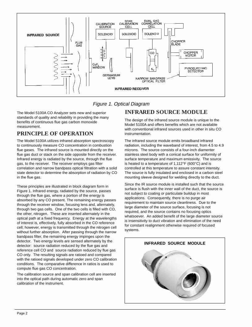
Figure 1. Optical Diagram
The Model 5100A CO Analyzer sets new and superiorstandards of quality and reliability in providing the manybenefits of continuous flue gas carbon monoxidemeasurement.
The Model 5100A utilizes infrared absorption spectroscopyto continuously measure CO concentration in combustionflue gases. The infrared source is mounted directly on theflue gas duct or stack on the side opposite from the receiver.Infrared energy is radiated by the source, through the fluegas, to the receiver. The receiver employs gas filtercorrelation and narrow bandpass optical filtration with a solidstate detector to determine the absorption of radiation by COin the flue gas.
These principles are illustrated in block diagram form inFigure 1. Infrared energy, radiated by the source, passesthrough the flue gas, where a portion of the energy isabsorbed by any CO present. The remaining energy passesthrough the receiver window, focusing lens and, alternately,through two gas cells. One of the two cells is filled with CO,the other, nitrogen. These are inserted alternately in theoptical path at a fixed frequency. Energy at the wavelengthsof interest is, effectively, fully absorbed in the CO referencecell; however, energy is transmitted through the nitrogen cellwithout further absorption. After passing through the narrowbandpass filter, the remaining energy impinges upon thedetector. Two energy levels are sensed alternately by thedetector: source radiation reduced by the flue gas andreference cell CO and source radiation reduced by flue gasCO only. The resulting signals are ratioed and comparedwith the ratioed signals developed under zero CO calibrationconditions. The comparative difference in ratios is used tocompute flue gas CO concentration.
The calibration source and span calibration cell are insertedinto the optical path during automatic zero and spancalibration of the instrument.
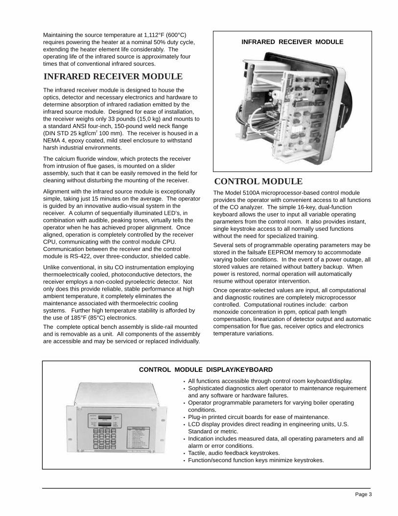
The design of the infrared source module is unique to theModel 5100A and offers benefits which are not availablewith conventional infrared sources used in other in situ COinstrumentation.
The infrared source module emits broadband infraredradiation, including the waveband of interest, from 4.5 to 4.9microns. The source consists of a four-inch diamenterstainless steel body with a conical surface for uniformity ofsurface temperature and maximum emissivity. The sourceis heated to a temperature of 1,112°F (600°C) and iscontrolled at this temperature to assure constant intensity.The source is fully insulated and enclosed in a carbon steelmounting sleeve designed for welding directly to the duct.
Since the IR source module is installed such that the sourcesurface is flush with the inner wall of the duct, the source isnot subject to coating or particulate buildup in mostapplications. Consequently, there is no purge airrequirement to maintain source cleanliness. Due to thelarge diameter of the source surface, focusing is notrequired, and the source contains no focusing opticswhatsoever. An added benefit of the large diameter sourceis insensitivity to duct vibration and elimination of the needfor constant realignment otherwise required of focusedsystems.
INFRARED SOURCE MODULE
INFRARED SOURCE MODULE
PRINCIPLE OF OPERATION
Page 3
CONTROL MODULE DISPLAY/KEYBOARD
• All functions accessible through control room keyboard/display.• Sophisticated diagnostics alert operator to maintenance requirement
and any software or hardware failures.• Operator programmable parameters for varying boiler operating
conditions.• Plug-in printed circuit boards for ease of maintenance.• LCD display provides direct reading in engineering units, U.S.
Standard or metric.• Indication includes measured data, all operating parameters and all
alarm or error conditions.• Tactile, audio feedback keystrokes.• Function/second function keys minimize keystrokes.
Maintaining the source temperature at 1,112°F (600°C)requires powering the heater at a nominal 50% duty cycle,extending the heater element life considerably. Theoperating life of the infrared source is approximately fourtimes that of conventional infrared sources.
The infrared receiver module is designed to house theoptics, detector and necessary electronics and hardware todetermine absorption of infrared radiation emitted by theinfrared source module. Designed for ease of installation,the receiver weighs only 33 pounds (15,0 kg) and mounts toa standard ANSI four-inch, 150-pound weld neck flange(DIN STD 25 kgf/cm2 100 mm). The receiver is housed in aNEMA 4, epoxy coated, mild steel enclosure to withstandharsh industrial environments.
The calcium fluoride window, which protects the receiverfrom intrusion of flue gases, is mounted on a sliderassembly, such that it can be easily removed in the field forcleaning without disturbing the mounting of the receiver.
Alignment with the infrared source module is exceptionallysimple, taking just 15 minutes on the average. The operatoris guided by an innovative audio-visual system in thereceiver. A column of sequentially illuminated LED’s, incombination with audible, peaking tones, virtually tells theoperator when he has achieved proper alignment. Oncealigned, operation is completely controlled by the receiverCPU, communicating with the control module CPU.Communication between the receiver and the controlmodule is RS-422, over three-conductor, shielded cable.
Unlike conventional, in situ CO instrumentation employingthermoelectrically cooled, photoconductive detectors, thereceiver employs a non-cooled pyroelectric detector. Notonly does this provide reliable, stable performance at highambient temperature, it completely eliminates themaintenance associated with thermoelectric coolingsystems. Further high temperature stability is afforded bythe use of 185°F (85°C) electronics.
The complete optical bench assembly is slide-rail mountedand is removable as a unit. All components of the assemblyare accessible and may be serviced or replaced individually.
INFRARED RECEIVER MODULE
The Model 5100A microprocessor-based control moduleprovides the operator with convenient access to all functionsof the CO analyzer. The simple 16-key, dual-functionkeyboard allows the user to input all variable operatingparameters from the control room. It also provides instant,single keystroke access to all normally used functionswithout the need for specialized training.
Several sets of programmable operating parameters may bestored in the failsafe EEPROM memory to accommodatevarying boiler conditions. In the event of a power outage, allstored values are retained without battery backup. Whenpower is restored, normal operation will automaticallyresume without operator intervention.
Once operator-selected values are input, all computationaland diagnostic routines are completely microprocessorcontrolled. Computational routines include: carbonmonoxide concentration in ppm, optical path lengthcompensation, linearization of detector output and automaticcompensation for flue gas, receiver optics and electronicstemperature variations.
INFRARED RECEIVER MODULE
CONTROL MODULE
Page 4
Diagnostic routines include, among many others: automaticzero and span calibration, continuous microprocessor self-interrogation of memory/software and hardware/mechanicalfunctioning status. Diagnostics are so comprehensive thatthey will alert the operator to preventative maintenancerequirements; so intelligent that they will differentiatebetween a dirty window or low source intensity. Noscheduled routine maintenance is required.
All measured data, operating parameters and fault or errorconditions are indicated on the easy-to-read, dual LCDdisplay. Readout is provided in engineering units, metric orU.S. Standard, at the operator’s choice.
In the event of a disabling fault or error condition, the Model5100A will automatically “hold” the output at the last validmeasured CO value. A held output condition is alsogenerated during automatic calibration cycles of theinstrument.
The Model 5100A control module is conveniently packagedin a lightweight, compact (5.22 x 10.61 inches/132 x 269mm), DIN-size enclosure with panel mount hardware. Asingle, three-conductor, shielded cable is all that is requiredto complete interconnection between the receiver and thecontrol room, further minimizing installation costs.
All printed circuit boards in the Model 5100A are modular,plug-in type, for ease of access and field replacement, ifrequired. All internal wiring and customer interconnectionsutilize modular plugs and DIN-style connectors, completelyeliminating problems associated with “hard wired” circuitry.
The absorption of infrared radiation by carbon monoxide incombustion flue gases is a function of flue gas temperature.The temperature affects the density of the gas and,therefore, the number of molecules encountered by theradiation. In addition, temperature variations inducevariations in the infrared absorption characteristics of carbonmonoxide. To account for these variations, flue gastemperature must be measured continuously. The Model5100A is provided with a separate, direct-insertionthermocouple for this purpose. Temperature data is input tothe receiver module and communicated to the controlmodule. The control module software is fully characterizedto provide accurate temperature compensation over the fullflue gas temperature range of 200°F to 600°F (93°C to316°C).
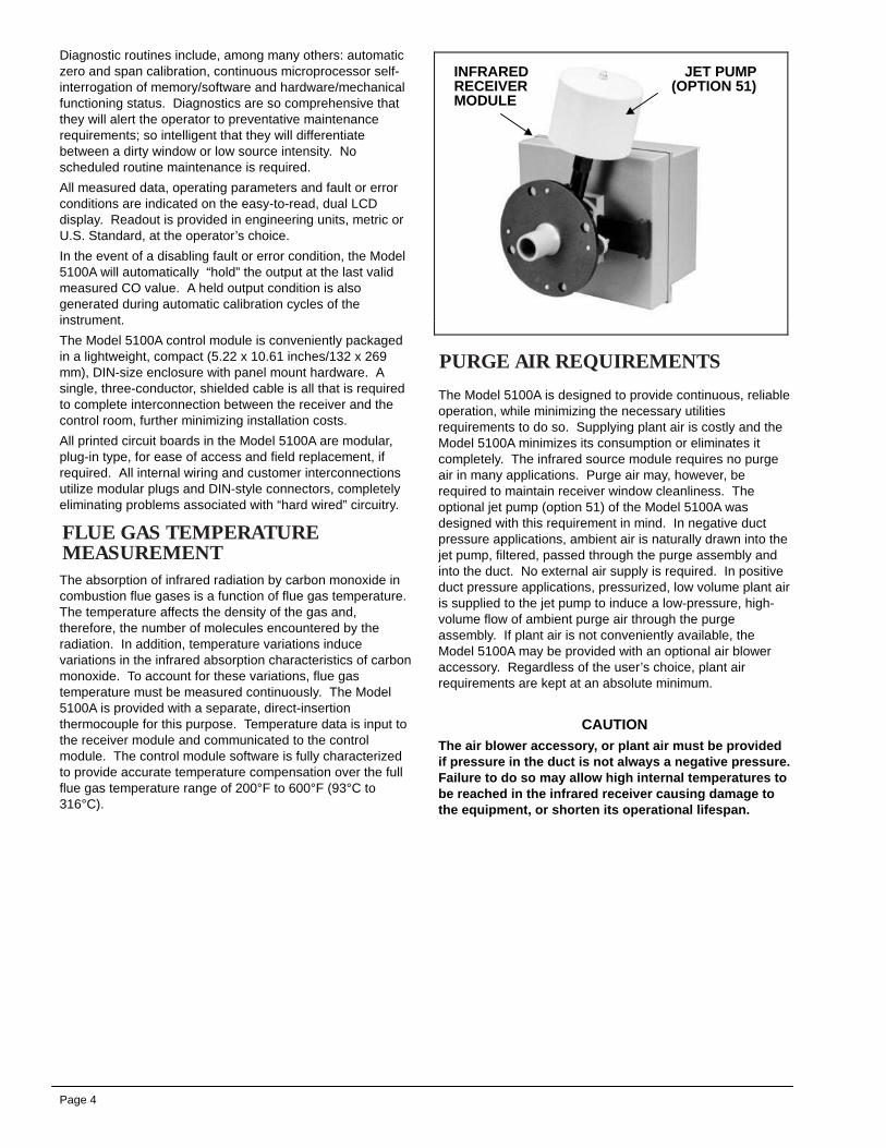
The Model 5100A is designed to provide continuous, reliableoperation, while minimizing the necessary utilitiesrequirements to do so. Supplying plant air is costly and theModel 5100A minimizes its consumption or eliminates itcompletely. The infrared source module requires no purgeair in many applications. Purge air may, however, berequired to maintain receiver window cleanliness. Theoptional jet pump (option 51) of the Model 5100A wasdesigned with this requirement in mind. In negative ductpressure applications, ambient air is naturally drawn into thejet pump, filtered, passed through the purge assembly andinto the duct. No external air supply is required. In positiveduct pressure applications, pressurized, low volume plant airis supplied to the jet pump to induce a low-pressure, high-volume flow of ambient purge air through the purgeassembly. If plant air is not conveniently available, theModel 5100A may be provided with an optional air bloweraccessory. Regardless of the user’s choice, plant airrequirements are kept at an absolute minimum.
CAUTIONThe air blower accessory, or plant air must be providedif pressure in the duct is not always a negative pressure.Failure to do so may allow high internal temperatures tobe reached in the infrared receiver causing damage tothe equipment, or shorten its operational lifespan.
INFRAREDRECEIVERMODULE
JET PUMP(OPTION 51)
PURGE AIR REQUIREMENTS
FLUE GAS TEMPERATUREMEASUREMENT

Page 5
The Infrared (IR) source module is installed with the sourcesurface flush with the inner wall of the duct in mostapplications. Therefore, the source is subject to onlyminimal coating or particulate buildup, and consequently,there is no purge air requirement to maintain sourcecleanliness. However, in certain applications, such as Kraftrecovery units and some waste incinerators, the flue gasescontain constituents, which can adhere to the source(despite the high surface temperature) and damage thesource through corrosion. In these applications, to protectthe source and reduce the need for periodic manualcleaning of the source surface (to maintain radiated intensityfor proper analyzer operation), a source air purge isrequired.
The source purge air assembly with jet pumps (option 53)consists of a carbon steel sleeve fitted with two jet pumps,one on either side as shown. These jet pumps are identicalto that used with the IR receiver module with the exceptionof being equipped without filters. The purge assembly isinstalled on the standard source mounting sleeve and the
source module is then installed in the purge assembly.Procedures and hardware for installing the source module inthe purge assembly are identical to those for installation inthe standard mounting sleeve.
When installed, the source surface is recessed from the ductwall at the rear of the cavity created by the mounting sleeveand the active forward section of the purge assembly. Auser supplied compressed air source is connected to the1/4-inch tube fitting on each jet pump. Compressed airrequirements are 6 SCFM (2.7 I/S) at 60 psig (413.7 kPag),3 SCFM (1.35 I/S) at each fitting. The jet pump is designedto accept the compressed air and induce a low pressure,high volume flow of ambient air through the purge assembly.The two jet pumps produce properly directly flows ofsufficient volume to effectively purge the cavity, shielding thesource from the flue gases.
The source purge air assembly with blower (option 55) maybe used when compressed air is not available for the jetpumps (option 53).
SOURCE PURGE AIR ASSEMBLY

Page 6
SOURCE PURGE AIR ASSEMBLY WITH JET PUMPS(OPTION 53)
SOURCE PURGE AIR ASSEMBLY WITH BLOWER(OPTION 55)

Page 7
INFRARED RECEIVER WITH JET PUMP (OPTION 51)
INFRARED RECEIVER WITH BLOWER ADAPTOR (OPTION 52)
MOUNTING DIMENSIONS
_-
Page 8

Page 9
SOURCE PURGE AIR ASSEMBLY WITH JET PUMPS(OPTION 53)
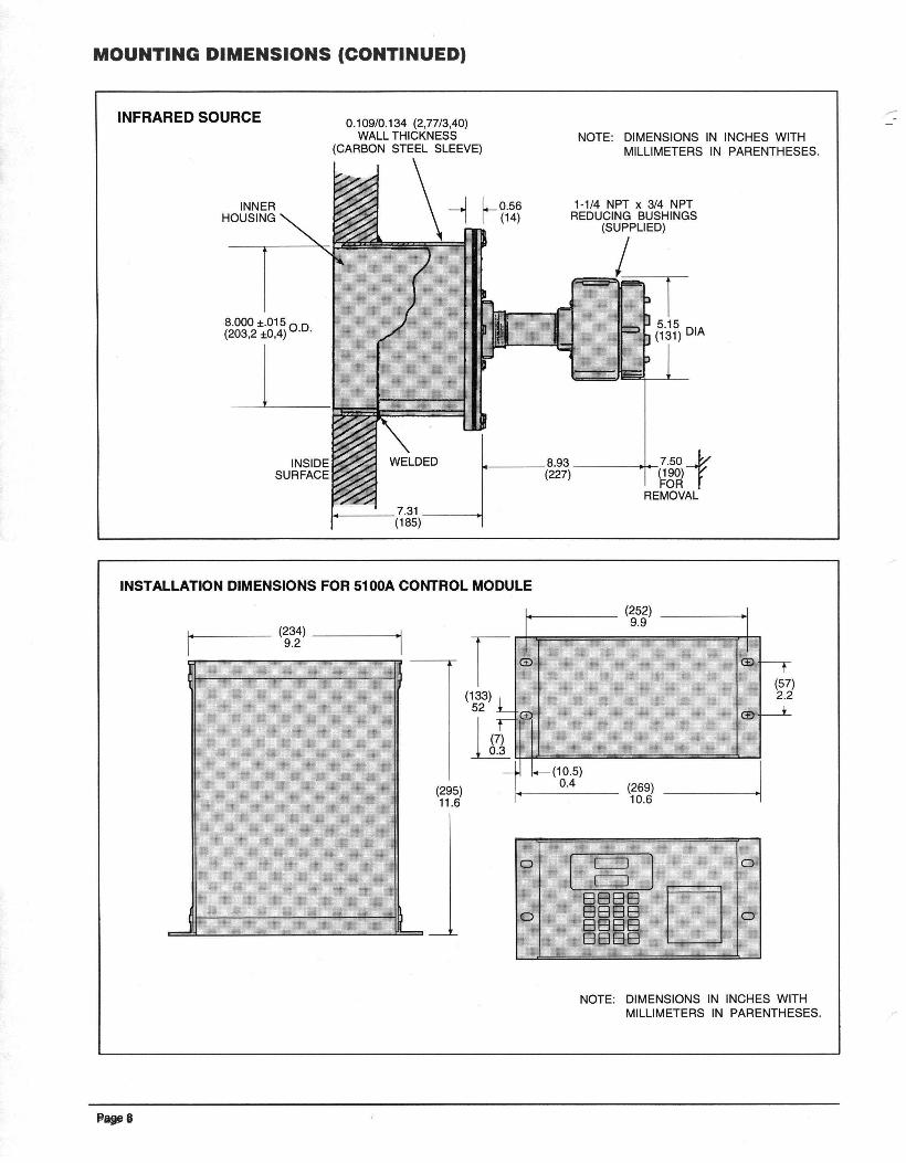
MOUNTING DIMENSIONS (CONTINUED)

Page 10
SOURCE PURGE AIR ASSEMBLY WITH BLOWER(OPTION 55)
MOUNTING DIMENSIONS (CONTINUED)

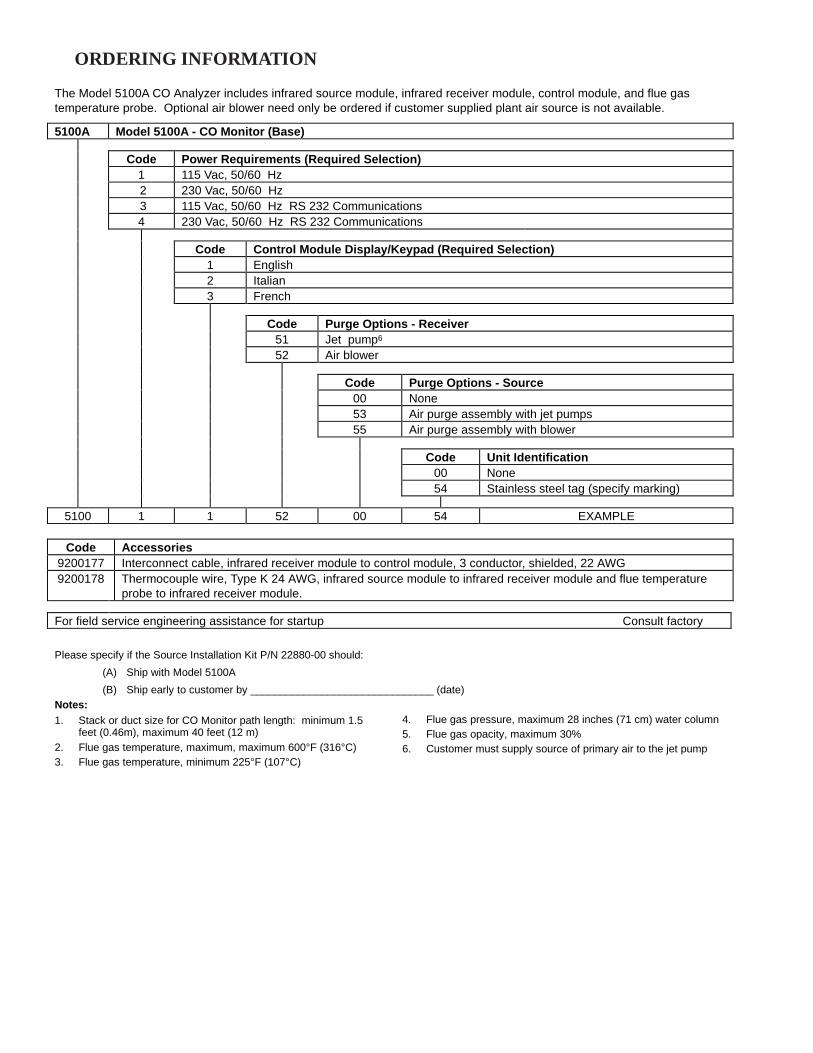
The Model 5100A CO Analyzer includes infrared source module, infrared receiver module, control module, and flue gastemperature probe. Optional air blower need only be ordered if customer supplied plant air source is not available.
5100A Model 5100A - CO Monitor (Base)
Code Power Requirements (Required Selection)1 115 Vac, 50/60 Hz 2 230 Vac, 50/60 Hz 3 115 Vac, 50/60 Hz RS 232 Communications4 230 Vac, 50/60 Hz RS 232 Communications
Code Control Module Display/Keypad (Required Selection)1 English2 Italian3 French
Code Purge Options - Receiver51 Jet pump6
52 Air blower
Code Purge Options - Source00 None53 Air purge assembly with jet pumps55 Air purge assembly with blower
Code Unit Identification00 None54 Stainless steel tag (specify marking)
5100 1 1 52 00 54 EXAMPLE
Code Accessories9200177 Interconnect cable, infrared receiver module to control module, 3 conductor, shielded, 22 AWG9200178 Thermocouple wire, Type K 24 AWG, infrared source module to infrared receiver module and flue temperature
probe to infrared receiver module.
For field service engineering assistance for startup Consult factory
Please specify if the Source Installation Kit P/N 22880-00 should:
(A) Ship with Model 5100A
(B) Ship early to customer by _______________________________ (date)Notes:1. Stack or duct size for CO Monitor path length: minimum 1.5
feet (0.46m), maximum 40 feet (12 m)2. Flue gas temperature, maximum, maximum 600°F (316°C)3. Flue gas temperature, minimum 225°F (107°C)
4. Flue gas pressure, maximum 28 inches (71 cm) water column5. Flue gas opacity, maximum 30%6. Customer must supply source of primary air to the jet pump
ORDERING INFORMATION


![Detecting Carbon Monoxide Poisoning Detecting Carbon ...2].pdf · Detecting Carbon Monoxide Poisoning Detecting Carbon Monoxide Poisoning. Detecting Carbon Monoxide Poisoning C arbon](https://static.fdocuments.in/doc/165x107/5f551747b859172cd56bb119/detecting-carbon-monoxide-poisoning-detecting-carbon-2pdf-detecting-carbon.jpg)


![Detecting Carbon Monoxide Poisoning Detecting Carbon ...2].pdf · Detecting Carbon Monoxide Poisoning Detecting Carbon Monoxide Poisoning. ... the patient’s SpO2 when he noticed](https://static.fdocuments.in/doc/165x107/5a78e09b7f8b9a21538eab58/detecting-carbon-monoxide-poisoning-detecting-carbon-2pdfdetecting-carbon.jpg)