Carbon Fiber SMC Technology for Lightweight · PDF fileCarbon Fiber SMC Technology for...
31
Carbon Fiber SMC Technology for Lightweight Structures The Composites Group 1 Matt Kaczmarczyk| Senior Design Engineer Quantum Composites - AS9100C:2009 / ISO9001:2008 1310 South Valley Center Drive Bay City, Michigan 48706-9798 USA Phone: 989-922-3863 ext. 116 Fax: 989-922-3915 [email protected] Tim Langschwager| Lead Development Chemist Quantum Composites - AS9100C:2009 / ISO9001:2008 1310 South Valley Center Drive Bay City, Michigan 48706-9798 USA Phone: 989-922-3863 ext. 120 Fax: 989-922-3915 [email protected]
Transcript of Carbon Fiber SMC Technology for Lightweight · PDF fileCarbon Fiber SMC Technology for...
Carbon Fiber SMC Technology for Lightweight Structu res
The Composites Group 1
Matt Kaczmarczyk| Senior Design Engineer
Quantum Composites - AS9100C:2009 / ISO9001:2008
1310 South Valley Center Drive
Bay City, Michigan 48706-9798 USA
Phone: 989-922-3863 ext. 116
Fax: 989-922-3915
Tim Langschwager| Lead Development Chemist
Quantum Composites - AS9100C:2009 / ISO9001:2008
1310 South Valley Center Drive
Bay City, Michigan 48706-9798 USA
Phone: 989-922-3863 ext. 120
Fax: 989-922-3915

Outline of Presentation
• What is Forged Composite?
• Differences Between CF-SMC and Traditional SMC
• High Flow vs. Low Flow Molding
The Composites Group
• Typical Mechanical Properties of CF-SMC
• Important Characteristics of CF-SMC
• CF-SMC Applications
• Processes Comparisons
2
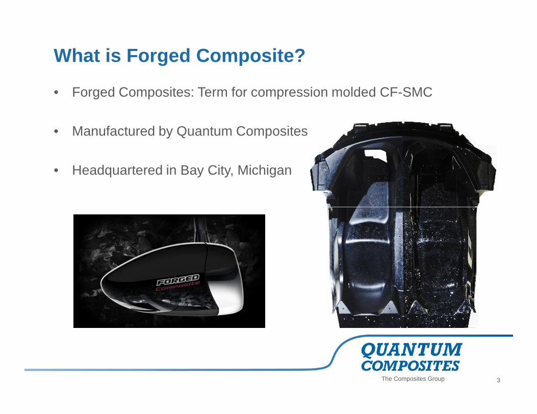
What is Forged Composite?
• Forged Composites: Term for compression molded CF-SMC
• Manufactured by Quantum Composites
• Headquartered in Bay City, Michigan
The Composites Group 3

CF-SMC First Branded as “Forged Composites”– October 2010 Paris Auto Show
The Composites Group 4
March 2012 Geneva (Aventador J) April 2012 Beijing ( Urus)
Courtesy: Dr. Paolo Feraboli – Automobili Lamborghini Advanced Composites Structures Laboratory

Carbon Fiber Sheet Molding Compound
• Glass fiber SMC has been around since the 1960’s
• In 1987 Quantum developed epoxy 3k carbon fiber molding compound
• CF-SMC have been in use since early 1990’s
• What is unique about CF-SMC?
The Composites Group
– Quasi-Isotropic properties
– Excellent for fastener-intensive and stiffness dominated parts
– Carbon fiber reinforcement
– High fiber content: Vf 40%+ / Wf 50%+
5

Carbon Fiber Sheet Molding Compound
Traditional SMC:
Sheet Molding Compounds (SMC) have traditionally been a low-performance process:
• Glass fiber
• Low fiber content: Vf 18%+ / Wf 25%+
• Low mold coverage/ high flow
• Typically polyester resin
• Higher specific gravity
The Composites Group
CF-SMC:
Feedstock material is chopped carbon fiber with resin
They are similar to prepreg in principle, but not in practice
We define Advanced Compression Molding to differentiate it from the traditional Compression Molding if:
• Carbon fiber
• High fiber content: Vf 40%+ / Wf 50%+
• Typically vinyl ester or epoxy resin but also BMI and phenolic
• Lower specific gravity
6

Advanced Compression Molding• Ability to use the CF-SMC in a repeatable and predictable way to form
unique applications
• Minimum molded thickness as low as 0.035 in. (1 mm)
• Reduced variability in strength
• Co-mold with selective UD reinforcement
• Understanding the requirements is the key to material selection
� Excellent for fastener-intensive and stiffness-dominated parts
The Composites Group
� Excellent for fastener-intensive and stiffness-dominated parts
7

Example Fabricated (Welded) Steel Tubing Compression Molded CF-SMC
21 lbs 8 lbs
Advanced Compression Molding
The Composites Group 8
Structural features such as ribs and gussets can easily be molded for
acceptable and even matched performance.

Advanced Compression Molding
• Matched-mold process
Figure 1. Mold is closing Figure 2. Mold is opening after cure
The Composites Group 9

High Flow MoldingSimilar to traditional SMC - fiber “orientation” is not controlled
Cut the material Weigh the charge Prepared Charge
The Composites Group 10
Cut the material Weigh the charge
Load the Charge
Courtesy: Premix
Prepared Charge

Low Flow MoldingSimilar to traditional lay-up - fiber “orientation” is more controlled
The Composites Group 11
Material is precisely cut and placed into mold

• Material flow and charge pattern can effect mechanical properties.
• Creating a uniform direction of fibers does not necessarily translate into improved strength.
• Flow fronts and fiber bunching creating weak areas in the coupons/parts.
40000
45000
Tensile Strength
7
8
Tensile Modulus
High Flow vs. Low Flow MoldingHigh Flow vs. Low Flow Molding
The Composites Group 12
0
5000
10000
15000
20000
25000
30000
35000
40000
High Flow Low Flow
(psi
)
0
1
2
3
4
5
6
7
High Flow Low Flow
(Msi
)

High Flow
High Flow vs. Low Flow Molding
The Composites Group 13
Low Flow

High flow specimen showing fiber bunching at
fracture area (Edge Effect at end of flow)
High Flow vs. Low Flow Molding
The Composites Group 14
Low flow specimen showing a more uniform fiber
displacement resulting in elevated strength properties.

Comparison of Material Performance
40.00
50.00
60.00
70.00
80.00
90.00
100.00
Te
nsi
le S
tre
ng
th (
ksi
)Tensile Strength vs. Tensile Modulus
Quasi-Iso
Tape
(15.2,174.0)
Ti-6-4
AL6061-T6
The Composites Group 15
0.00
10.00
20.00
30.00
40.00
0 2 4 6 8 10 12 14 16 18 20
Te
nsi
le S
tre
ng
th (
ksi
)
Tensile Modulus (Msi)
Discontinous Carbon Fiber Molding CompoundReference Materials
Glass SMC

Fiber Aspect Ratio
3K – 3,000 filaments per tow (roving)
12K – 12,000 filaments per tow
3k=100 tows
12k=25 tows
• Higher Fiber Aspect Ratio =
– Higher performance
– Lower COV strength values
– Higher notch sensitivity
The Composites Group 16
12K – 12,000 filaments per tow
50K – 50,000 filaments per tow
50k=6 tows

Comparison of Carbon Fiber Tow (CF -SMC)
30,000
40,000
50,000
60,000
70,000
Te
nsi
el
Str
en
gh
t (p
si)
Tensile Strength comparison of ASTM Method
3K SMC
12K SMC
The Composites Group 17
*ASTM D-638 in the graph above uses “as molded” net shape test specimen.
ASTM D3039, D5766, and D6742 use specimen machined from molded plaques.
0
10,000
20,000
ASTM D-638 ASTM D 3039 MD ASTM D 3039 CMD ASTM D 5766 MD ASTM D 6742 MD
Te
nsi
el
Str
en
gh
t (p
si)
Test Method
12K SMC
50K SMC

Comparative Properties of CF -SMC
• Moduli as high as prepreg quasi baseline• Unnotched strengths lower than prepreg quasi baseline• Compression higher than tension• Open-hole strengths more appealing• Higher CoV in strength and modulus
� Excellent for fastener-intensive and stiffness-dominated parts
The Composites Group
� Excellent for fastener-intensive and stiffness-dominated parts
18
UNT[ksi]
CoVT mod [Msi]
CoVOHT [ksi]
UNC [ksi]
C mod [Msi]
OHC [ksi]
Aluminum 30 2% 10.0 0% 30 30 10.0 30Quasi-isotropic fabric
T700/977-6108 4% 6.0 5% 60 70 4.9 45
3k CF-SMC 47 10% 5.0 10% 37 52 5.4 37
12k CF-SMC 29 18% 5.5 27% 29 42 6.0 33
50k CF-SMC 22 20% 5.5 20%

Comparative Fatigue Curves
25,000
30,000
35,000
40,000
45,000
50,000
UT
S (
psi
)
S-N curve
3K CF-SMC
The Composites Group 19
Tension – Tension 3Hz
0
5,000
10,000
15,000
20,000
0 200000 400000 600000 800000 1000000
Life (Cycles)
12K CF-SMC
AL6061-T6

Notched Behavior • Specimens containing open holes fail both in the net and gross section
• Typical fastener hole size ¼-inch diameter hole
98.6% failed at hole
1.4% failed away from hole3k
The Composites Group 20
73.6% failed away from hole
26.4% failed at hole12k

Effects of Defects
• Difficult for Non Destructive Inspection: signal is noisy
• Ultrasonic scans reveal areas of weak reflection or “Hot
Spots” – not necessarily defects
The Composites Group 21
DE-LAMINATION FLAW

Modulus Variability
• Modulus measurements either
via strain gage or extensometer
• High variability encountered
(approx 19%) much higher than
strength variability (approx 10 %)
• Experiments using gage lengths
of 0.125, 0.25, 0.5, 1.0 and 2.0
The Composites Group 22
of 0.125, 0.25, 0.5, 1.0 and 2.0
in.
• Also 1.0 in. extensometer
• Longer gages do not yield better
measurements
• Measurements vary along length
and across width of specimens

Modulus Variability
• Digital image correlation (DIC)
• Black speckles are applied to a white background on one side of a specimen
• Images are taken during testing by a pair of digital cameras
The Composites Group
by a pair of digital cameras
• Post processing allows to measure full field strain
• Measurement shows local variations
23

Fiber Orientation• High degree of influence on mechanical properties, stiffness
• Changes with high flow vs. low flow molding process and part geometry
• Molded specimens will give high mechanical values due to favorable fiber orientation.
• With cut specimens, the fibers are cut in the gage length reducing the strengths by about 25-30% from molded specimens.
Fibers tend to orient in the direction of flow
The Composites Group 24
Fibers tend to orient in the direction of flow and along the cavities edge.
ASTM D 3039 CUT FROM PANEL
Fibers are random, but cut at the parts edge
ASTM D 638 MOLDED SPECIMEN

Outline of Presentation
• What is Forged Composite?
• Differences Between CF-SMC and Traditional SMC
• High Flow vs. Low Flow Molding
• Typical Mechanical Properties of CF-SMC
The Composites Group
• Important Characteristics of CF-SMC
• CF-SMC Applications
• Processes Comparisons
25

Carbon-Fiber Sheet-Molded Composite Underbody Diffuser for Nissan GTR
Challenge Lower cost, parts consolidation
Solution• Lower part cost vs. prepreg parts
• Corrosion resistance
CF-SMC Applications
The Composites Group
• Corrosion resistance
• High stiffness
• Good impact strength
• Dimensional stability
• Ability to mold in ribs, bosses, changes in thickness (e.g., for attachment points)
26

Carbon-Fiber Sheet-Molded Composite Monocoque Tube and Suspension Arm for
Lamborghini Siesto Elemento
Challenge Lower cost, cycle time
Solution• Much lower part cost vs. prepreg parts• Lightweight• High stiffness / strength
CF-SMC Applications
The Composites Group
• High stiffness / strength• Faster cycle time than RTM• Higher volume compression molded• Hybrid structures (e.g., Continuous + Discontinuous
Fibers)
27

CF-SMC Applications
The Composites Group 28

Additional CF -SMC Applications
The Composites Group 29
Carbon fiber hood inner structure
http://www.sae.org/mags/sve/12288/
Carbon fiber fender support

Injection Molding
RTM
Compression Molding
(CF-SMC)
Transfer
Molding
Composite Fabrication Processes (thermoset)
The Composites Group 30
Spray-up
Autoclave / Vacuum
Bag
Hand
Lay-up
Production Volume
Too
lin
g C
ost

Thank you!
The Composites Group 31