Carb Rebuilding Honda DOHC-4’s - · PDF file© 2010 & 2013 – MacGregor Carb...
42
© 2010 & 2013 – MacGregor Carb Cleaning Service MacGregor Carb Cleaning Services 04/13/2013 Volume 1, Issue 6 BOLT-ON AND GO! Carburetor cleaning and rebuild services for all Honda 4 cylinder double-overhead cam models (1979-1983) Carb Rebuilding Honda DOHC-4’s
Transcript of Carb Rebuilding Honda DOHC-4’s - · PDF file© 2010 & 2013 – MacGregor Carb...

© 2010 & 2013 – MacGregor Carb Cleaning Service
MacGregor Carb Cleaning Services04/13/2013
Volume 1, Issue 6
BOLT-ON AND GO!Carburetor cleaning and rebuild services for all Honda 4 cylinder double-overhead
cam models (1979-1983)
Carb RebuildingHonda DOHC-4’s

© 2010 & 2013 – MacGregor Carb Cleaning Service
Table of ContentsPURPOSE............................................................................................................................................................................................................... 3
BASIC CARB TERMS ............................................................................................................................................................................................... 3
GETTING STARTED................................................................................................................................................................................................. 3
BASIC TOOLS.................................................................................................................................................................................................................... 4SPECIALTY TOOLS .............................................................................................................................................................................................................. 4WITHOUT CHEMICALS, LIFE ITSELF WOULD BE IMPOSSIBLE... ........................................................................................................................................................ 5
PARTS LIST ............................................................................................................................................................................................................ 5
HARDWARE ..................................................................................................................................................................................................................... 6“SOFTWARE”................................................................................................................................................................................................................... 6
STEP 1 - BANK BREAKDOWN.................................................................................................................................................................................. 7
SPLIT THE BANK................................................................................................................................................................................................................ 7DOWN TO SINGLE CARBS....................................................................................................................................................................................................7
STEP 2 -INDIVIDUAL CARB BREAKDOWN ............................................................................................................................................................... 9
SYNC SCREWS .................................................................................................................................................................................................................. 9TOP END ...................................................................................................................................................................................................................... 10AIR CUTOFFS ................................................................................................................................................................................................................. 11SPECIAL CARB #2 PARTS TO REMOVE ................................................................................................................................................................................... 11BOTTOM END (THE SCARY STUFF) ....................................................................................................................................................................................... 11ACCELERATOR PUMP IN CARB 2 ......................................................................................................................................................................................... 13THROTTLE BUTTERFLIES ....................................................................................................................................................................................................14
STEP 3 - OFF TO THE CLEANERS.............................................................................................................................................................................14
CLEANING THE BIG PARTS ..................................................................................................................................................................................................15CLEANING THE SLOW SPEED JETS........................................................................................................................................................................................ 18CLEANING THE ACCELERATOR PUMP NOZZLES ....................................................................................................................................................................... 19CLEANING CARB #2 ......................................................................................................................................................................................................... 20CLEANING THE LITTLE PARTS .............................................................................................................................................................................................. 20SPECIAL THINGS TO LOOK FOR ............................................................................................................................................................................................ 21
STEP 4 - REBUILD – GETTING IT TOGETHER ...........................................................................................................................................................21
INDIVIDUAL CARB ASSEMBLY ............................................................................................................................................................................................. 21(Benny and the) Jets ............................................................................................................................................................................................. 22Float Valve Seats (Shine on you crazy diamond) .................................................................................................................................................. 23Pilot Screws .......................................................................................................................................................................................................... 23Float & Valve........................................................................................................................................................................................................ 24Finishing out the Bottom End (1, 3 & 4) ............................................................................................................................................................... 24Special Carb 2 Assembly....................................................................................................................................................................................... 26Accel Pump and Bowl Install ................................................................................................................................................................................ 27Air Cuts................................................................................................................................................................................................................. 28
STEP 5 - BUILDING UP THE CARB BANK.................................................................................................................................................................29
RIGHT SIDE (CARBS 3&4) ................................................................................................................................................................................................ 30LEFT SIDE (CARBS 1&2)...................................................................................................................................................................................................30MAKING THEM WHOLE (LEFT & RIGHT) ............................................................................................................................................................................... 32FINAL ASSEMBLY ............................................................................................................................................................................................................ 34
STEP 6 – ADJUSTMENT, TESTING & TROUBLESHOOTING.......................................................................................................................................35
ALIGNMENT................................................................................................................................................................................................................... 35FINAL TOUCHES.............................................................................................................................................................................................................. 38BYPASSING THE AIR CUTOFFS ............................................................................................................................................................................................. 39REMOVING BUGGERED-UP PILOT SCREWS ............................................................................................................................................................................ 40
SERVICES OFFERED ...............................................................................................................................................................................................42

© 2010 & 2013 – MacGregor Carb Cleaning Service
PurposeThe purpose of this booklet is to de-mystify the 4-ganged carburetor banks used onthe ’79-’83 Honda DOHCs (750cc – 1100cc). Having some basic tools, plus a fewinexpensive specialty tools, a modicum of mechanical capability and common sense- you can tear down, clean and rebuild your carbs in a short weekend. This bookletwill show you how. The pictures shown are for a CB900, but will be nearly identicalfor CB750, CB1000 and CB1100 with slight differences, which will be noted. Theprocess is in 6 steps:
1. Bank breakdown2. Carb breakdown3. Clean4. Carb rebuild5. Bank rebuild6. Adjustment, testing and troubleshooting
Basic Carb TermsThe carbs are numbered the same way as the cylinders on the bike – 1 through 4left to right as you sit on the bike. The fronts of the carbs have the silver-coloredthrottle plates (butterflies), and the rear of the carbs have the brass-colored chokeplates. The round tops are called caps and the square bottoms are called bowls.
Getting StartedFirst, get yourself an areato work – it can be agood-and-proper shopworkbench, or even asimple table (appropriatelycovered and protectedfrom spilled liquids andsolvents) and a comfychair. My downstairsbasement is set up withjust a large coffee table covered with thick cardboard. You need to have enoughroom to set up your tools, layout the parts of the carbs and a cleaning area to cleanthe parts. You’ll want a plastic pan such as those used for oil changes for cleaningthe individual parts prior to assembly. It should be impervious to the chemicalsused in spray carb-cleaner or brake-cleaner.

4 © 2010 & 2013 – MacGregor Carb Cleaning Service
Additionally, you’ll want a copy of the Factory Service Manual to refer to as you go.The FSM is the bible by which all work on our bikes should be validated.Finally, make sure you read through this booklet all the way through at least twice tofamiliarize yourself with the procedures BEFORE you start disassembly. Nothingworse than ending up with a pile of really important looking parts after it’s all backtogether! If you don’t feel completely confident in what you find in this booklet, by allmeans grab a digital camera, a bunch of plastic sandwich bags and a Sharpie® penand document your work as you go.
Basic toolsIn addition to your workbench and cleaningtray, here’s what I recommend for basictools:
Medium flat-blade screwdriver Medium Phillips-head screwdriver Large Phillips-head screwdriver Small flat-blade screwdriver Vice-Grips® 4” Crescent wrench 1” wire brush (1 each steel and brass) Needle nose pliers Package of 4” acid brushes (sometimes called solder-flux brushes) with the
bristles trimmed to ¼” length Paper towels & Q-Tips®
Additional tools that you might need: Flat file Flashlight Magnifying glass Box-knife Ultrasonic cleaner (Harbor Freight has them for about $60)
or Large bucket to soak your carbs in
Specialty toolsOver and above the tools noted previously, here are some specialty tools that willmake the job a snap (and some you’ll need for other jobs on the bike anyway):
Motion-Pro carb sync tool (shown at the top of page 36) High E-string from an old guitar (approx .012” diameter)

© 2010 & 2011 – MacGregor Carb Cleaning Service 5
Paperclip (straightened out) with1/8” 90º bend at the end (on theright in the picture)
Center-punch (not shown) Hand drill and assorted drill bits
from 1/32” to 1/8” (not shown) Small EZ-Outs® Special spray-straw taped up to fit
in slow-speed jet hole (just to theleft of the paperclip)
without Chemicals, life itself would be impossible...In addition to the tools, you’ll need some wet-stuff to make the cleaning job goeasier.
¾ Gallon can of carb-degreaser (with small-parts basket)and/or
Gallon jug of Pine-Sol® or otherammonia-based pine cleaner
Carb (or brake) cleaner spray withstraw spray nozzle
WD-40 or a can of your favorite spraylube (I use white lithium spraygrease)
PB Blaster to loosen corroded screwsand parts
Nitrile or Latex gloves – thesechemicals can be pretty nasty on theskin (not to mention carcinogenic)
Wrap-around eye protection (required safety equipment to protect your eyesfrom the spray chemicals!)
Kona Pipeline Porter or other adult beverage (optional)
Parts ListSo you got your carbs and your carb rebuild kits – well done. If you bought theRandakk kits, you’re golden – everything you need is in those kits - but here aresome parts that are left out of most after-market rebuild kits, as well as someniceties that make the job go smoothly.
6 © 2010 & 2013 – MacGregor Carb Cleaning Service
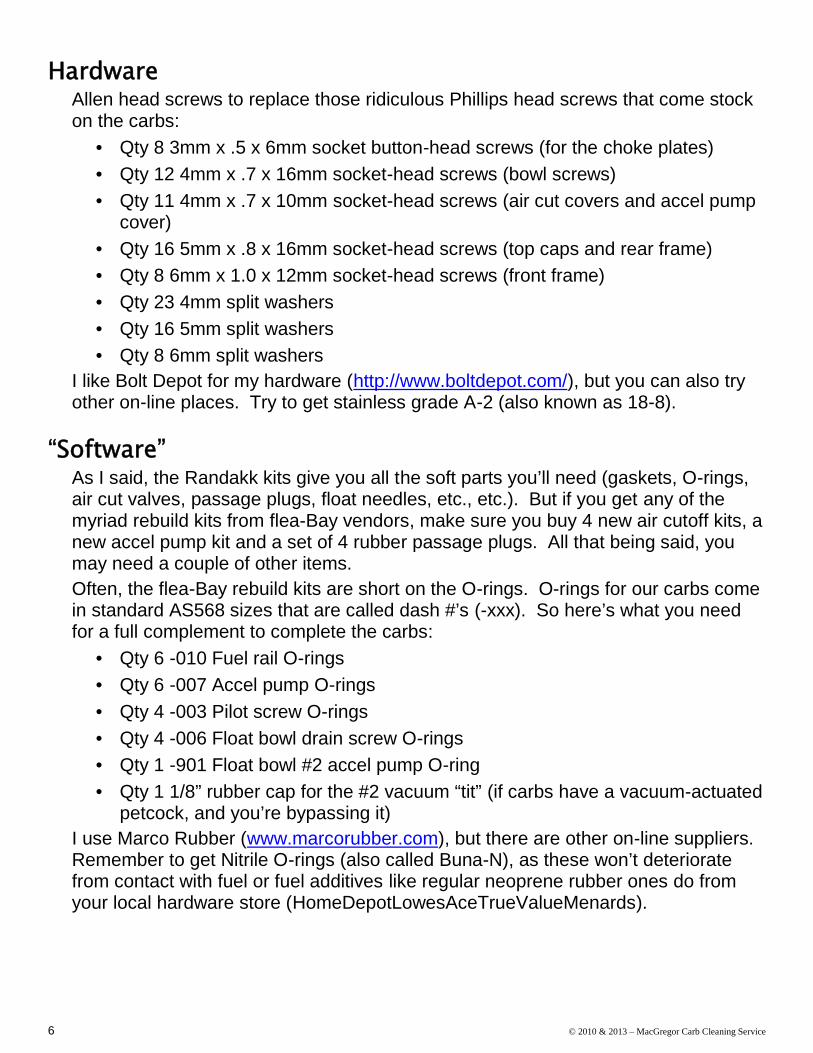
HardwareAllen head screws to replace those ridiculous Phillips head screws that come stockon the carbs:
Qty 8 3mm x .5 x 6mm socket button-head screws (for the choke plates) Qty 12 4mm x .7 x 16mm socket-head screws (bowl screws) Qty 11 4mm x .7 x 10mm socket-head screws (air cut covers and accel pump
cover) Qty 16 5mm x .8 x 16mm socket-head screws (top caps and rear frame) Qty 8 6mm x 1.0 x 12mm socket-head screws (front frame) Qty 23 4mm split washers Qty 16 5mm split washers Qty 8 6mm split washers
I like Bolt Depot for my hardware (http://www.boltdepot.com/), but you can also tryother on-line places. Try to get stainless grade A-2 (also known as 18-8).
“Software”As I said, the Randakk kits give you all the soft parts you’ll need (gaskets, O-rings,air cut valves, passage plugs, float needles, etc., etc.). But if you get any of themyriad rebuild kits from flea-Bay vendors, make sure you buy 4 new air cutoff kits, anew accel pump kit and a set of 4 rubber passage plugs. All that being said, youmay need a couple of other items.Often, the flea-Bay rebuild kits are short on the O-rings. O-rings for our carbs comein standard AS568 sizes that are called dash #’s (-xxx). So here’s what you needfor a full complement to complete the carbs:
Qty 6 -010 Fuel rail O-rings Qty 6 -007 Accel pump O-rings Qty 4 -003 Pilot screw O-rings Qty 4 -006 Float bowl drain screw O-rings Qty 1 -901 Float bowl #2 accel pump O-ring Qty 1 1/8” rubber cap for the #2 vacuum “tit” (if carbs have a vacuum-actuated
petcock, and you’re bypassing it)I use Marco Rubber (www.marcorubber.com), but there are other on-line suppliers.Remember to get Nitrile O-rings (also called Buna-N), as these won’t deterioratefrom contact with fuel or fuel additives like regular neoprene rubber ones do fromyour local hardware store (HomeDepotLowesAceTrueValueMenards).
© 2010 & 2011 – MacGregor Carb Cleaning Service 7
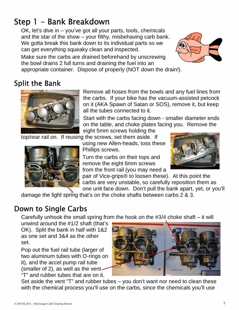
Step 1 - Bank BreakdownOK, let’s dive in – you’ve got all your parts, tools, chemicalsand the star of the show – your filthy, misbehaving carb bank.We gotta break this bank down to its individual parts so wecan get everything squeaky clean and inspected.Make sure the carbs are drained beforehand by unscrewingthe bowl drains 2 full turns and draining the fuel into anappropriate container. Dispose of properly (NOT down the drain!).
Split the BankRemove all hoses from the bowls and any fuel lines fromthe carbs. If your bike has the vacuum-assisted petcockon it (AKA Spawn of Satan or SOS), remove it, but keepall the tubes connected to it.Start with the carbs facing down - smaller diameter endson the table, and choke plates facing you. Remove theeight 5mm screws holding the
top/rear rail on. If reusing the screws, set them aside. Ifusing new Allen-heads, toss thesePhillips screws.Turn the carbs on their tops andremove the eight 6mm screwsfrom the front rail (you may need apair of Vice-grips® to loosen these). At this point thecarbs are very unstable, so carefully reposition them asone unit face down. Don’t pull the bank apart, yet, or you’ll
damage the light spring that’s on the choke shafts between carbs 2 & 3.
Down to Single CarbsCarefully unhook the small spring from the hook on the #3/4 choke shaft – it willunwind around the #1/2 shaft (that’sOK). Split the bank in half with 1&2as one set and 3&4 as the otherset.Pop out the fuel rail tube (larger oftwo aluminum tubes with O-rings onit), and the accel pump rail tube(smaller of 2), as well as the vent“T” and rubber tubes that are on it.Set aside the vent “T” and rubber tubes – you don’t want nor need to clean thesewith the chemical process you’ll use on the carbs, since the chemicals you’ll use

8 © 2010 & 2013 – MacGregor Carb Cleaning Service
might damage them. Set them aside where you can find them later. Place the fueland accel pump rail tubes in your tray for cleaning. Note: if this is a CB1000 orCB1100 bank, there won’t be a fuel rail tube between 2 & 3.Start with the 3/4 set – rotate the choke shaft so that the 4 choke plate screws areaccessible. Carefully and slowly, unscrew them making sure you don’t strip themout (drilling these out can be problematic). The screws areflared on the backside to keep them from rattling loose fromnormal bike vibration (and getting sucked into the intake),so they take some work to remove. Here is where youmight want the larger Phillips screwdriver to get a good biteon the screws.Set aside the screws if reusing - though I stronglyrecommend using new stainless 3mm socket button-headscrews here. The old screws are very difficult to get restarted in the shaft holesonce they’ve been flared, so if you can, use new 3mm screws and throw these oldones away.Place the 2 choke plates in the small parts tray for later cleaning.Slide the choke shaft out and put with the other parts in the small-parts tray. Pull
the 3 & 4 carbs apart and remove the fuel railand accel pump tubes as well as the ventrubber tube. Don’t lose the little throttle springthat pops out from between the 2 carbs, you’llneed it later! Set aside the rubber tube andput the rail tubes, choke plates and throttlespring in the small parts tray. Note: if this is aCB1000 or CB1100 bank, there won’t be a fuelrail tube between 3 & 4, but this will be a smallbrass T-fitting with O-rings.
Now move on to the carb 1 & 2 set – this set is a bit trickier to break apart becauseyou have to hold the choke arm closed with one hand while you remove the chokeplate screws with the other. Take your time, and again, make sure you’re getting agood bite with the screwdriver – you don’t wantto strip out those screw-heads.Once you’ve removed the 4 choke screws,
carefullyremove thechoke shaftand chokespring (it willbe hookedto the main choke arm).

© 2010 & 2011 – MacGregor Carb Cleaning Service 9
Before popping 1 & 2 apart, remove therear cap screw off #1 – this holds a clipthat keeps the brass fuel source “T” frommoving around.Again, set aside the rubber vent tube, andplace the fuel “T”, accel pump tube, chokeplates and throttle spring in the small partstray.Parts set aside:
Vent T with rubberconnection tubes
2 rubber vent tubes
Parts in the cleaning tray: Eight 5mm screws and eight 6mm screws (unless replacing w/Allen heads) Front and rear rails Two 1” throttle springs 4 choke plates 2 choke shafts & 1 choke shaft spring Fuel “T” and 2 fuel rails (may be 2 fuel
“T’s” only if this is a 1000 or 1100 bank) 2 short and one long accel pump rail
tubes
Step 2 -Individual Carb BreakdownOK, so you should be gaining confidence in your ability to work with theseconvoluted creatures – heck, you’ve successfully taken the bank apart, andnothing’s broken yet! Now it’s time to get jiggy with the carbs themselves.Fortunately, each one is a copy of the others (with the notable exception of carb #2).We’ll start with carb #1 and move on to #3 & #4. Pay attention to your first one andthe other two will go just like it! Carb #2 will be the last one we do since it’s morecomplicated; it may look scary, but we’ll get you through it.
Sync ScrewsBefore we dig into the guts of the carbs, let’s remove one last external item – thesynchronizing screws off carbs 1, 3 & 4. Here’s where you’ll want that specializedMotion-Pro tool (see picture on page 36) to loosen the locknuts and remove thesync screws themselves. If you don’t have the good-and-proper tool, you can use a

10 © 2010 & 2013 – MacGregor Carb Cleaning Service
4” crescent wrench, or an 8mm socket to loosen thelocknuts. The screws are removed from their tabs byscrewing them INTO the tabs (clockwise). There are 2flat washers and a small spring on each one – don’t losethem. Add them to the small parts tray (cinch thelocknut down on the spring first, though, so you don’tlose any little parts).
Top EndOK, let’s remove the easy stuff – the top-caps, springs and vacuum needle “pucks”.Again, if reusing the screws, set them in with the smallparts tray; otherwise toss ‘em.Once you have the top-cap, spring and puck removed,remove the plastic seal-ring and the kidney-shaped
plastic air jetcover. Put thesprings, seal-rings and air jetcovers (withscrews) in thesmall parts tray.

© 2010 & 2011 – MacGregor Carb Cleaning Service 11
Air CutoffsCarefully remove the 2 screws holding the air cutoffcover while holding the cover down (there’s a strongspring under the cover). Before putting the cover andthe spring in the small parts tray, inspect the cover andbody to make sure the smallO-ring isn’t stuck in it (it’susually in the body) – eitherway, remove it and set itaside. Remove the air cutdiaphragm and inspect withstrong backlighting to ensure
it isn’t cracked, worn, perforated or otherwisecompromised. It is possible to reuse these or bypassthem altogether. We’ll get to that in the rebuild section. Ifyou’ve already bought new ones, just toss the olddiaphragms, springs and O-rings – your new kits shouldhave all these parts. Put the screws in the small partstray, unless replacing with new socket heads.
Special Carb #2 parts to removeRemove the throttle cable mount (held in place by a 5mmPhillips screw), highidle knob, washer andspring, and the chokeidler arm, spring andwashers (be gentlewith the spring - it’sdelicate).Place all these parts inthe small parts tray.
Bottom End (the scary stuff)OK, let’s dive into the “scary stuff” (it’s really not thatscary). Remove the bowl drain screws and put them inthe small parts tray. Then remove the three 4mmscrews holding the float bowl in place and pull the bowloff – you may have to rap on the bowl with the handle-end of the screwdriver to break it free. Set the bowl

12 © 2010 & 2013 – MacGregor Carb Cleaning Service
Primary main jetemulsion tube downhere
Slow-speed jet downhere
aside, and put the screws (if reusing) in the small parts tray.Inside, you’ll see the jets, the float and the passage plug. Next we’ll remove thefloat. Take that straightened out paperclip you made in the tools section above andpush the float pin out; the float and float valve will come out together. Set the floatand valve aside, and put the pin in the small parts tray.
Remove and toss the rubber passage plugs (you’ll be installing new ones later).Use a medium flat-blade screwdriver
to remove the primary main jet(screwed directly into the body of thecarb). Use your crescent wrench toremove the brass secondary main jetemulsion tube (it has the secondarymain jet screwed into it). Put boththese into the small parts tray.Special note – the silver needlejet isheld in place by the secondary main
jet
emulsion tube, and MAY fall out when you removethe tube. If so, put it in the small parts tray as well.Now take a look down the pipe that the rubberpassage plug came out of. Look to see if the slow-speed jet has a slot in it for a flat blade screwdriver(later ‘81s through the ‘83s had removable slow-
speed jets; earlier ones were press-in and notremovable). If the slow-speed jet has a slot in it,remove it by unscrewing it with a small flat blade.Remove the primary main jet emulsion tubeby using the screwdriver part of the Motion-Pro
sync tool (it fits perfectly in the hole). Get a goodbite on the slot and don’t force it. These get
corroded insometimesand you can
do more damage to the thing by stripping out thescrew slot. If it’s stuck in there, try spraying somePB-Blaster down the hole and let it sit overnight.Worse case, you can clean the carbs with theemulsion tube still installed – don’t damage itunnecessarily trying to remove it if it’s good-and-

© 2010 & 2011 – MacGregor Carb Cleaning Service 13
O-ring
Flat washer
truly stuck. If you were able to remove the emulsion tube and if the slow-speed jetwas removable, place both in the small parts tray.Remove the pilot screws by unscrewing them counter-clockwise. Inspect it to
ensure it has a 1/8” needle tip to it as shownin the pics. When removing the pilot screws,they may come out with the spring, or thespring may remain in the body – here’s whereyou want the other end of the paperclip.Use the 90º “hook” to fish out the spring (if itdidn’t come out with the pilot screw), and the
flat washer and O-ring. Here’s where your flashlightwill help. Put the pilot screw, spring and flatwasher inthe parts tray – toss the O-ring.
If your old pilot screwshad the silver stop tabson them, you canremove them by using aheat gun or a hairdryeron high temp setting. Apair of needle nose pliers will suffice to take them off.
There should be enough glue still inside the cap to heat up when you’re ready to putthem on your new pilot screws.
Accelerator Pump in Carb 2Carb #2 is special in a number of ways, as you’ve already seen.The last special thing we’ll work with is the accelerator pump –a small diaphragm, spring and set of special check-valves thatsquirt fuel directly into the throat of each carb when the throttleis twisted briskly. This is meant to overcome the “turbo-lag” ofthe heavy vacuum needle pucks that make these CV carbs sounique.You’ll notice when you removed the #2 carb bowl, there were 3
other screws on the base of it – this houses the pump. Be careful with the shaft thatpokes up out of the bowl – don’t bend it! Remove thethree screws (hold on to the cap as there’s a strongspring underneath). Remove the cap, the spring and thediaphragm/shaft. While the diaphragm and spring canbe reused, it’s better to replace ‘em – usually only about$25 from most e-Bay vendors. Place the screws (ifreusing), accel pump cap and spring in the small partstray.

14 © 2010 & 2013 – MacGregor Carb Cleaning Service
Set the diaphragm/shaft aside after inspecting forstiffness/brittleness/holes/cracks/thin-spots with aback-light. You hopefully still have a small rubberbellows that fits in the #2 carb body that the accelpump shaft went through. Check its condition andset aside with the other rubber parts. Specialnote about foreign carbs: Not all carbs sold byHonda are the same. Many of our UK-associatedbikes (Britain, South Africa, Australia, etc.) doNOT have an accel pump. Instead, carb #2’sbowl looks just like carb #1’s bowl. So IF you have a set of these simpler carbs, justignore all references to accel pump in the document.
Throttle ButterfliesI don’t recommend removing the throttle butterflies and throttle linkages. A coupleof reasons for that: You risk damaging or tweaking the shafts unless you remove theparts in the right order, you risk losing or damaging the small felt washers that areinside the bronze inserts (these parts were not offered by Honda, so you’d have tomake new ones if you lose/damage one), and there’s a high probability of gettingthe fiber and metal washer sequence buggered up on re-installation and creatingpaths for an air-leak. Frankly, the risks don’t warrant the additional cleaning youcould get on those parts, so I say – leave ‘em on. OK, now on to cleaning…
Step 3 - Off to the CleanersOK – You’re a third of the way there, and the parts tray is getting pretty full! Inaddition to the parts I detailed in the bank breakdown section above, you shouldhave:
3 sync screws with springs, locknuts and flat washers 4 primary main jets 4 secondary main jets in their emulsion tubes 4 float pins 4 pilot screws/springs/flat washers 4 top-cap springs 4 float-bowl drain screws 4 top-cap plastic seal rings 4 top-cap plastic air-jet covers and screws 1 throttle cable support bracket and 5mm screw 1 high-idle screw/knob/washer/spring 1 choke idler arm with spring, bolt, flat and split washers

© 2010 & 2011 – MacGregor Carb Cleaning Service 15
4 air cutoff springs, covers and screws 1 accel pump cover, spring and screws 4 primary main jet emulsion tubes (if you were successful in removing them) 4 slow-speed jets (if the removable type) 1 or more silver needle-jets (if they came out with the secondary jet emulsion
tubes)Set aside should be:
4 air cutoff diaphragms 4 air cutoff diaphragm O-rings 4 floats 4 float valves 1 accel pump diaphragm/shaft and rubber bellows
And of course the big parts: 4 carb bodies 4 carb caps 4 vacuum “pucks” 4 float bowls
OK, it’s time to clean this stuff up!
Cleaning the big partsAs seen in this pic, I use both theCarburetor and Small Parts Cleaner Dipfrom Gunk® and a 3-quart ultrasoniccleaner. The Dip comes in a 3-quart canand has a nice perforated small-partsbasket, which can safely hold even thesmallest of all the parts in your parts tray.The ultrasonic cleaner is the same sizeand can take a full carburetor (body, cap,puck and bowl). Used together, they’ll
clean off nearly all your caked on oil andgrime from the outside of the carb, as wellas the varnished gasoline throughout allinternal surfaces of the carb bodies. Nowothers will swear by a simple 2-gallon pail,and a gallon of Pine-Sol®. It’s up to you –both methods work well.I place the carb body face down in thebasket and lower it into the Dip, then (after

16 © 2010 & 2013 – MacGregor Carb Cleaning Service
removing the float-bowl gasket) position the other 3 major pieces around it sothey’re all covered in the thick liquid. Let it sit in there anywhere from 15 minutes toovernight depending on how nasty your parts are. Usually 30 minutes is plenty.Remove the parts and put in the ultrasonic – I use Pine-Sol® as the liquid for theultrasonic. I run ‘em for 15 to 20 minutes, then put them in the cleaning pan andrepeat the whole process for the next carb. You may have to turn the bodies in theultrasonic, so all the surfaces are well vibrated.If you use the simple Pine-sol®-‘n-bucket method, place all the parts in the bucket,fill with Pine-sol® and let sit overnight. Don’t let them sit for more than a day thoughwithout rinsing, as the Pine-Sol® may attack the aluminum.After you get them out and rinsed/dried, it’s time to put on the eye protection as weclean the carb body.Take a couple of the acid brushes, trim the bristles down to about ¼” and use thespray carb cleaner to clean out those nooks and crannies on the bodies. Use thecarb cleaner generously throughout the carb body, and use the acid brushes toattack any dirt that the Dip and ultrasonic cleaner didn’t remove – you want thebodies spotless on the inside.Clean the top-cap with the carb spray, and use a paper towel stuffed loosely in thecenter tube to buff it clean, as well as the inside of the top-cap itself – any schmutzinside here will impede the puck’s vacuum movement and affect the bike’soperation. Take the straw and spray through the little hole on the side of the top-cap inner tube – it should spray into the inner tube.Spray down the vacuum puck and use the acid brush to clean off any varnished gason it or the needle. Stick some of the paper towel down between the inner edges ofthe puck and its center shaft – just like the top-cap, any schmutz here will impedethe puck in its travels.
Use the carb cleaner spray and the acidbrushes to clean out any residual gunk in thebottom of the float bowl. Use a Q-Tip® toclean out the seat of the float bowl drainscrew. Start with a full tip, and then pull offenough of the cotton off the end of the Q-Tip®to go all the way through into the base of thefloat bowl. Trust me; they’ll be black with goo– keep using the Q-Tips® and carb spray untilthey are clean.Take the spray straw and an Exacto®-type
knife and whittle the tip to a more conical shape so it fits better into some of theholes you’ll be spraying into (this will keep the back-spray into your face to aminimum – don’t ask me how I know this…).

© 2010 & 2011 – MacGregor Carb Cleaning Service 17
Spray a good shot into each hole asfollows:
Primary main air jet Secondary main air jet Secondary slow air jet Primary slow air jet Air cutoff feed Air bypass
Also Float valve seat Slow-speed jet Accel pump feed hole
(shown later) Primary main jet Pilot screw Secondary main jet

18 © 2010 & 2013 – MacGregor Carb Cleaning Service
Cleaning the Slow Speed JetsThere’s nothing more important for proper carb operation than having clean slow-speed jets, so I’m going to dedicate several pix to help you.If the jets were removable, you’re golden - just blow them out with some carbcleaner before reinstalling, but if the slow-speed jets were the pressed-in variety,and you could not remove them in the carb breakdown section, you need to prepthem for spray-down:
Take that E-string wehad you get, and pushit through the centerhole down in thecenter tube – don’tforce it; you may needto twist it as you go,but you want to beable to push down
about 1-1/2” of the E-string down the holeto be sure you’ve cleared the slow-speed jet.They gunk up easily and will cause no end of grief if you don’t getthem cleared. Don’t short-change this step – it’s critical.Once cleared with the E-string, here is where you want to modify the straw. Take
enough electrical tape and wrap it around the end sothat it will fit fairlysnug in the slow-
speed jet tube. Hold a thumb over the primarymain-jet hole and your index finger over the lower
air cutoff hole andspray. If the slow-speed jet is truly clear,you’ll get abubbling (orstream) of carbspray out the pilotscrew hole. Don’tconsider the carbcleaned until youcan do that!

© 2010 & 2011 – MacGregor Carb Cleaning Service 19
Cleaning the Accelerator Pump NozzlesFinally, check that the accel pump nozzleis clear by setting the carb down on itsfront, carefully place the conical nozzle ofthe straw into the accel pump rail holeand watch the pump nozzle as you spray –you should get a nice clear stream outthe pump nozzle tip. On carb #1, the railhole is on the right side of the carb. On#4 it’s on the left. On carb #3 you can gofrom either side, just cover the other railhole with your finger so the spray goesout the nozzle. Clearing that nozzle is abugger, as it’s a blind hole on the carb-body side of the nozzle. You can use your needle-nose pliers to hold the E-stringand blindly search for the hole – once you’ve found it, wiggle the string in there, andtry again. You may have to soak the carb body and run it through the ultrasoniccleaner again to clear this nozzle.That should take care of all the big parts – drop the puck into the top cap and makesure it slides effortlessly – polish the inside of the cap and the puck again with apaper towel, if you get any hesitation. Also polish the vertical sides of the carb bodywhere the puck goes with a paper towel to further ensure proper carb operation.If you want to polish your carb caps and bowls to a chrome-bright shine, now wouldbe the right time to get that done.

20 © 2010 & 2013 – MacGregor Carb Cleaning Service
Cleaning carb #2Everything you did on carbs 1, 3 & 4 will be done on carb #2, but there are more
nooks-‘n-crannies to deal with – take the timeto clean the body well with the acid brushesand carb cleaner.To clear the accel pump nozzle on carb 2, thehole is accessed from the bottom of the carb,with your thumband forefingercovering both railholes. Also, thefloat bowl has acheck-valve that
needs to be cleared. Spraying into this hole shouldresult in a jet of spray out each of the 4 sidesof the square brass insert. You may have tosoak the bowl further if this check-valve isclogged.
Cleaning the little partsThe easiest way to clean the little parts is tosoak them in the Dip tank for 30 minutes, thenultrasonically clean them for 30 minutes. Spray them down with carb cleaner, touch‘em up with the acid brushes, and dry them in preparation for rebuild.3 parts you’ll want to do some extra effort on: choke shaft 1/2, choke shaft 3/4, andthe accel pump cap.Use a brass brush to get the residual crud off the choke shafts and get ‘em shiny-bright (they need to be able to spin easily in the choke shaft bushings in the carbbodies). Be careful not to bend the shafts.
And just like in the #2 float bowl, there’s a check-valve inthe accel pump capthat needs to becleared. The carbspray nozzle should fitdown the larger of thetwo holes in the cap,and the spray shouldcome briskly out each
of the 4 sides of the square brass insert. If itdoesn’t, you’ll need to soak the cap longer andrun it through the ultrasonic again.

© 2010 & 2011 – MacGregor Carb Cleaning Service 21
Sometimes you can soak just the check-valve, by setting the cap right side up in thespray-can cap, and fill it with carb spray. Let it sit for an hour or so, and try again.Run spray through each jet and emulsion tube, paying special attention to theaeration holes on the sides (make sure they’re clear).
Special things to look forThere’ve been a few parts that have been set aside that now need to be looked at.Take each float and hold it near your ear and shake it back and forth – if you hearANY sloshing about, you need to replace it, as it developed a leak where fuel isgetting inside, and it won’t work right for you. If the carbs have been sitting for awhile, the fuel may have evaporated out of an otherwise leaking float, so you mightwant to put each of them in a cup of water, with something to hold them down. Let‘em sit for an hour or so and check again with the shake test.If you didn’t get new float valves with your rebuild kit, it is possible to reuse your oldones – look closely at the rubber tip with a magnifying glass and make sure it’sconical, a bit pliable and doesn’t have a groove worn into it. Also, make sure thesilver tip on the other end can be pushed in, and springs back easily when released.Take a look at the pilot screws under the magnifying glass and make sure the tipsare not damaged or bent. If you get new ones with your rebuild kits, you can chuckthe old ones (actually it’s probably better to save ‘em as spares!).
Step 4 - Rebuild – Getting it TogetherOK, we’ll go through this just like the disassembly and cleaning; carb #s 1, 3, 4 thencarb #2.We’ll build up each individual carb, then gang them together in 2’s then hook the 2gangs up. Nothin’ to it, eh?
Individual Carb AssemblyStart at the top of the carb. Install the plasticairjet cover and screw in snuggly (not tightly –you don’t want to break the cover). Then installthe seal ring – the inner lip should be facing up.Take the vacuum “puck” and drop it down intothe top of the carb. The groove in the side ofthe vacuum puck fits neatly on the tab stickingout from the airjet cover. Look through the rearof the carb as you drop the puck in, so theneedle fits into the needle jet (sticking up abovethe bottom of the throat of the carb), and thegroove fits onto the tab of the airjet cover. If
the needlejet came out with the needlejet holder (back on step 2 middle of page 12),

22 © 2010 & 2013 – MacGregor Carb Cleaning Service
you won’t see it in the carb throat – we’ll install it in the nextstep – don’t worry.Now install the spring onto the already installed puck andinstall the carb cap on the spring (make sure the spring fitsaround the outside of the brass center tube of the carb cap).Snug it all together with two 5mm screws.
(Benny and the) JetsTake your magnifying glass and look along the edges of all 4 primary main jets andsecondary main jets. There should be some markings on them like K68 or K105.Make sure all the primaries are the same number, and all the secondaries (in theiremulsion tubes) are the same number. Invariably during a previous clean/rebuild,the owner will have removed the secondaries from their emulsion tubes and mixedthem up with the primaries on reinstall. That’s why I recommend removing thesecondary emulsion tube while leaving the jet installed in it – keeps this mix-up fromhappening. Stock jetting (with airbox) for our bikes is as follows:
750 – 68 primaries and 100 or 102 secondaries 900 – 68 primaries and 105 secondaries 1000 – 68 primaries and 110 secondaries 1100 – no primaries (and no rubber passage
plug!) and 122 secondaries.Install the primary mainjet emulsion tube (ifyou were able tosuccessfully removethem before), and the
primary main jet. Check for the silver needle jetsticking up above the bottom of the carb throat inthe center of the carb body. If it’smissing, and you have one ormore in the clean tray, install itnow. It will only go in one way, so
don’t force it – The conical end goes up, and the rounded endgoes down.

© 2010 & 2011 – MacGregor Carb Cleaning Service 23
Install the secondary main jetemulsion tube (this will holdthe needle jet in). Now, if youremoved the slow-speed jet,install it now and put in afresh rubber passage plug –make sure it fits snugly anddoesn’t fall out when you turn
the carb over.
Float Valve Seats (Shine on you crazy diamond)Without a doubt, the second most important thingabout your carb cleaning process (right after the slow-speed jet and passage cleanliness) is the float valveseats. More people complain about their carbspissing fuel out the overflow tubes, and it’s almostalways caused by dirty float valve seats. Get yourselfa handful of Q-Tips®and some Brasso®,
or other metal polish (or even some toothpaste, ifyou don’t have any polish). Polish those seatsuntil they shine. Examine them with a magnifyingglass and flashlight to make sure there are no pits,grooves or damage down near the edge of the fuelentrance hole of theseats.
Pilot ScrewsSlide the spring onthe pilot screw,followed by the flat washer then a new O-ring.Screw the whole assembly into the body of thecarb. Screw it all the way in until you feel
resistance – DON’Tforce it, or the littleneck below thethreads will giveway, and you’ll begetting out the drill and EZ-Outs®. Once the flatsection below the thin neck is even with the bottom ofthe pilot screw hole, you’ll be bottomed out. On the900, 1000, and 1100 carbs, you will see a bit of thepilot screw tip sticking up through the bottom of the

24 © 2010 & 2013 – MacGregor Carb Cleaning Service
carb throat; you won’t be able to see that on the 750’s. Now back the pilot screwout the following amount:
750’s – 3 turns 900’s – 2-1/2 turns 1000’s and 1100’s – 3-1/2 turns
Float & ValveYou’ve tested your floats and they float! Clean ‘em upand reinstall them with either new or cleaned-up-and-tested old valves. Install the valve onto the float and slidethe valve into the seat while aligning the float for the pin.Slide the pin all the way in so no part of the pin can beseen on either side of the float holders. Turn the carb onits nose until the float just touches the silver tip of thevalve and measure the distance between the bottom ofthe float and the bottom of the carb body. It should bewithin the specs of the Factory Service Manual (15.5mm+/- 1mm). The brown plasticfloats on the ‘80s and later
bikes are not adjustable as far as float height – if youhave a float level issue with these floats, it’s likely yourvalve is bad or the wrong one for that model. On the’79 CB750’s, you’ll find black floats – the valves areslightly different (they have a wire clip on them) and thefloats have a metal tang on them that IS adjustable.
Finishing out the Bottom End (1, 3 & 4)Alright, we are getting close to buttoning up our carbs. Next step is to install new O-rings on the bowl drain screws. While it’s a good idea toreplace all the old O-rings with new, these screws canprobably be used with the old O-rings; the rings don’t preventleakage out the overflow, but just keep the fuel from comingout the side when the drain screw is loosened. But it IS a good idea to check thescrew tips for damage. They should not be pitted, gouged or missing. Often, watercollecting in the bottom of the bowls will corrode the tips (bad screw on top, good
screw on bottom). Before installing the bowl onto the carb, fillthe bowl with water to within 1/8” of the top of the bowls andmake sure you get no leaks – nothing worse than dealing witha leaky bowl AFTER you’ve assembled everything andinstalled the carbs on the bike.

© 2010 & 2011 – MacGregor Carb Cleaning Service 25
Split drain tube repairedwith J.B. Weld ™
Sometimes, the drain tube will get a crack in it, or the drain screw seat is damaged.You can fix the tube with some solder or J.B. Weld™.
The only way to fix a damaged drain seat is to replace thebowl. To check for a cracked drain tube, screw in the drainscrew and snug it down, then hold your finger over the upperend of the tube and spraycarb cleaner into the drainnipple– if there’s a crack,you’ll see carb cleanerspraying out through it,otherwise,it’ll onlycome out asback-sprayout thedrain nipple.
All that’s left now to the bottom end is to install the floatbowl with new gasket. Dry out the bowls well from yourleak test.I find I have to stretch the bowl gasket gently throughmy fingers a few times to get it to seat right in the
groove. I don’t use gasket seal or any adhesive, as the stretching usually worksfine. Place the carb body onto the bowl (with everything upright) so the gasketstays in place. Place strong pressure on the bowl to hold it in place while you flip itover and install the three 4mm screws. Loosely install the screws, and then snugthem down evenly before tightening them all up. The passage plug will be forcedcompletely into the slow-speed jet tube once these screws are fully tightened up.Now’s a good time to reinstall the pilot-screw cap that you removed before – justhold it with a pair of needle nose pliers, heat it up with a heat gun or hair dryer andsoften the glue. Align it straight ahead of the tab on the bowl and push on to the topof the pilot screw. By having it aligned straight ahead, you can still adjust it 1/3 of aturn in or out without hitting the bowl tab (you may need to adjust the final setting ofthe pilot screws on the bike to get the right mixture level).
26 © 2010 & 2013 – MacGregor Carb Cleaning Service
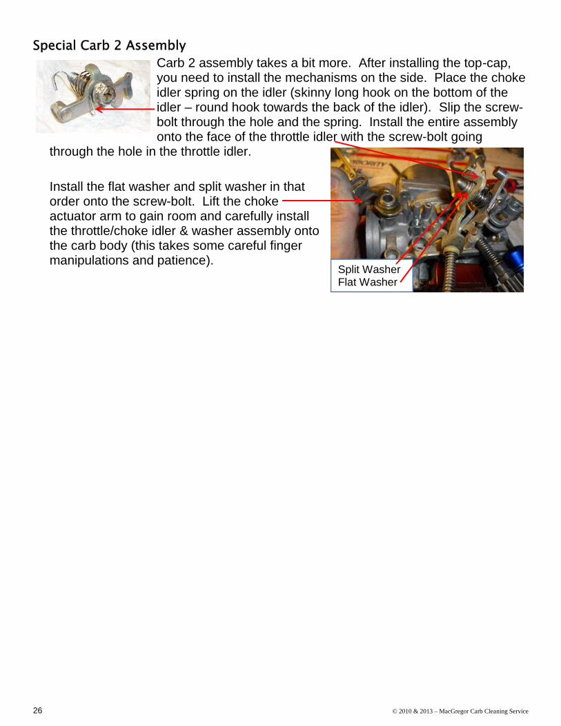
Special Carb 2 AssemblyCarb 2 assembly takes a bit more. After installing the top-cap,you need to install the mechanisms on the side. Place the chokeidler spring on the idler (skinny long hook on the bottom of theidler – round hook towards the back of the idler). Slip the screw-bolt through the hole and the spring. Install the entire assemblyonto the face of the throttle idler with the screw-bolt going
through the hole in the throttle idler.
Install the flat washer and split washer in thatorder onto the screw-bolt. Lift the chokeactuator arm to gain room and carefully installthe throttle/choke idler & washer assembly ontothe carb body (this takes some careful fingermanipulations and patience).
Split WasherFlat Washer

© 2010 & 2011 – MacGregor Carb Cleaning Service 27
Start the screw-bolt into the hole onthe body (the idler’s round endshould be towards the back of thecarb, and the forked tines should betowards the front. Before tighteningdown, make sure the round part ridesunder the choke actuator arm, and
the tines fit under thethrottle actuator arm,and the round hook ofthe spring should fit overthe solid stud just
forward of the chokeactuator arm.
The whole thingshould end uplooking like this:
Now install the throttle cable mount with the 5mmscrew (the hole on the left goes onto the small stud justbelow and back of the screw hole).While the picture shows it installed, it’s best to hold offinstalling the high-idle knob/spring/washer until you’vegot the bowl installed.
Accel Pump and Bowl InstallBefore you install the float bowl on carb #2, you shouldinstall and test the accel pump. Slide the diaphragm shaftthrough the hole in the center of the accel pump housing onthe bowl and align the holes on the side of the diaphragmwith the holes in the housing. While maintaining that hole
alignment, install the springand screw down the cover withthree 4mm short screws.Make sure the spring fits overthe check-valve “lump” in thebottom of the cover. Snug the screws down evenly,and then tighten them up. Take the whole assemblyout in the garage, and over a large catch pan fill thebowl about half full with fuel and test the pump
operation. Obviously do this is a safe environment (garage door open, eye

28 © 2010 & 2013 – MacGregor Carb Cleaning Service
protection on, gloves on, plenty of shop rags around, no open flames). You shouldget a 6-18” fountain of gas squirt out the square brass diffuser when you press
down on the diaphragm shaft (it may take acouple of priming shots). If you don’t, you needto troubleshoot – it’s usually a reused diaphragmthat’s shot, or a check-valve that’s not clear.I recommend using gas, as water can end upbeing left in the pump chamber - since it’s thelowest point on the carbs – it’ll corrode yournewly cleaned accel pump. Gas won’t do that.Once tested and drained/cleaned up, install a
bowl gasket and the 901-sized O-ring over the bowl diffuser depression. Install thedust-protector bellows up through the carb body (thicker/wider end of the rubber atthe bottom). Hold the bowl and carb in their upright positionand install the bowl onto the carb, carefully holding the bellowsin place as you guide the shaft through it and make sure thegasket and O-ring stay in place as you mate the bowl to thebody. Hold the bowl firmly to the body and install the three4mm long screws – again snug them up evenly, thentighten down.Now you can install the high idle knob/screw/spring/washer – the washer should gobetween the knob and the spring. Screw it in until it touchesthe throttle actuator arm, and then give it another full turn.
Air CutsTake the air cutoff cover,place the conical tip of thestraw into the hole in thecorner and spray – you should get a jet out theside hole just beside it. If you got new diaphragmkits, install the diaphragm (make sure the brass tipeasily slides into the hole, and the diaphragm lipfits securely in the groove). Place the rubber O-
ring in the hole in the lower left corner of the air cutoff hole in the body of the carb.The flat side should go against the body. Install thespring (small end towards you), and install the cover.Make sure the small “tit” on the cover fits into thesmall end of the spring. Secure with two 4mm shortscrews. Make sure nothing has moved out of place(diaphragm still in its groove, O-ring still in its spot,spring still in the diaphragm) and tighten down the screws.

© 2010 & 2011 – MacGregor Carb Cleaning Service 29
Step 5 - Building up the Carb BankWhoo Hoo! Two-thirds there. Let’s review the parts you have on the table, so wecan rectify it before we go any farther:
4 complete carbs with tops, bowls and air-cuts installed 2 choke shafts with spring 2 throttle springs 3 sync screws with spring, washers and locknuts 1 brass fuel “T” (Maybe 2 “T’s” if these are 1000 or 1100 carbs) 2 short and 1 long accel pump tubes 1 short and 1 long fuel tube (or none if 1000 or 1100 carbs) 4 choke plates 1 Fuel “T” clip 1 Vent “T” and rubber joiners 2 rubber vent tubes Front rail and rear rail with choke cable clip 8 each 5mm and 6mm screws
If you have ANY other parts than these, go backthrough the step 4 and see where you left anything out.Go ahead now and replace the oldie-moldy O-rings on the fuel and accel pump railtubes and fuel “T(s)”. A touch of petroleum jelly or WD-40 makes these go on easilyas well as lube them for easy installation into the carb bodies themselves.

30 © 2010 & 2013 – MacGregor Carb Cleaning Service
Right Side (Carbs 3&4)Like we did in section 2, we’ll start with the easy ones first.Insert the short fuel rail (or short brass “T” if 1000 or 1100carbs) in the fuel port on carb 3. Install the short accelpump tube in the accel pump port on carb 3. Install one ofthe 2 rubber vent tubes on the vent port on carb 3. Placingcarbs 3 and 4 face down, mate up carb 4 to carb 3’s tubes.Twist the accel pump and fuel rails as you press the carbstogether so you get a firm seating of the O-rings in theirports. Make sure carb 4’s throttle sync tab is over the top
of carb 3’s sync tab.Slide the choke shaft through the 2 carbs from the carb
3 side – make sure it goesall the way into the right sideof the carb 4 body. Theshaft you want is the onewith the two small tinessticking off of it (one tine
has a notch in it). Twist the shaft so the reliefs cutinto the shaft are facing you (slightly facing down)and install a choke plate on each relief, and installnew 3mm x .5 x 6mm screws into the choke shaft –tighten them down, then back them off 1 full turn –we’ll cinch ‘em down later in the build. Make surethe choke shaft can turn 90º easily – if it binds, youmay have to recheck that the tubes are fully seatedin their ports.
Left Side (Carbs 1&2)OK, we do the same thing with carbs 1&2, butyou need to be a bit more of a contortionist forthis set.Install the brass fuel “T” into carb 1’s fuel port (thelonger of the 2 ends of the T should go into carb1). Install the short accel pump tube in carb 1’saccel pump port. Install the second of the 2rubber vent tubes on the vent port on carb 1.Placing carbs 1 and 2 face down, and mate upcarb 2 to carb 1’s tubes. Twist the accel pump and fuel “T” as you press the carbstogether so you get a firm seating of the O-rings in their ports. Make sure carb’ssync tab is over the top of carb 2’s.

© 2010 & 2011 – MacGregor Carb Cleaning Service 31
Now is where it gets tricky. Slide the choke spring ontothe choke shaft. Note thatthere’s two hooks on thisspring – one is vertical(bent in the same plane asthe coils of the spring itself),and the other is horizontal.Put the vertical hook side of the spring on first – it should
be up against the tabs of the shaft. Slide theshaft into the pair from the carb 2 side. As youget the tip close to the left side of the carb #1body, you’ll have to lift the choke actuatingmechanism on carb #2 to slip the horizontal tabof the shaft under it.At the same time, you want to hook thehorizontal hook of the spring onto the chokeactuating mechanism. Here, a picture is worth athousand words. Don’t worry about the verticalhook of the spring; we’ll get to that in a bit.Make sure the shaft is fully seated against thechoke actuator, and the tip is fully engaged in the left side of carb #1. Thehorizontal tab of the shaft should be just under the choke actuator. Here’s where a3rd hand would help. Use one hand to lift the actuator and the choke shaft together,
so the choke plate reliefs are pointed towardsyou. Place a choke plate on #2’s relief andloosely install two 3mm x .5 x 6mm screws.Snug them up and back them off 1 full turn.Repeat for carb #1.Work the choke mechanism a few times andmake sure the choke plates move easilywithout binding – as with carbs 3/4, make sure
the fuel T and accel pump tubes are fully seated in their ports, and that the rubbervent tube isn’t binding.
We’ll use that bent paperclip again here, as we set up thespring to receive the right half bank. Turn the 1 / 2 half bank onits carb #1 side. Use your thumb and forefinger to turn thespring counterclockwise to get that horizontal hook onto thechoke actuator tab. The vertical hook will be barely showingjust above or below the shaft tab – you may have to twist thespring counterclockwise to get the vertical hook to show itselfBELOW the tab.

32 © 2010 & 2013 – MacGregor Carb Cleaning Service
Once you do that, grab it with the hook with the paperclip, andbring it around counterclockwise and hook it to the vertical tab ofthe choke shaft (here’s where the pics help).
Now, install the long fuel tube (unless theseare 1000 or 1100 carbs), and the long accelpump tube, as well as the vent “T” on carb #3in preparation for bringing the two halves together.
Making them whole (Left & Right)OK, one last tricky part (here’s where I usually swearlike a sailor). As you connect the two halves together,be careful not to bump the vertical hook of the chokespring off of its perch on the vertical tab of the chokeshaft. You want to loosely insert the left sides of thevent tube, fuel tube and accel tube into/onto theirrespective ports of carb 2, but watch carefully as thetines from the 3 / 4 choke shaft get close to the chokespring. When it’s right up against the spring, take either
a pair of needle-nose pliers, or the bent paperclip and carefully move the hook tothe notch in the rear tine of the 3 / 4 choke shaft.The forward tine should now rest upon the verticaltab of the 1 / 2 shaft. It’s likely you’ll bump thespring the first couple of times you try this, and thespring will unwind. Go back and rewind it with thebent paperclip and try again. Once you have ithooked up, double check that the throttle sync tabof carb #3 is ON TOP of the one on #2. Then pressthe two halves together, spin the accel and fueltubes to ensure they’re well seated, give another good shove together and you’renearly done!

© 2010 & 2011 – MacGregor Carb Cleaning Service 33
Some more pictures that will help you:
Looking down & forwardfrom above

34 © 2010 & 2013 – MacGregor Carb Cleaning Service
Final AssemblyOK, go grab a glass of your favorite adult beverageand congratulate yourself! We’re nearly done; a fewmore screws, a little more swearing, and your carbswill be ready to rock and roll.Start with the rear rail – install with the 8 remaining5mm screws. Snug them up only finger tight – we’ll
tighten them during the alignment phase.Flip the carbs on their tops and install the front rail with the 8 remaining 6mmscrews. Again, only snug themup finger tight.
Check that the throttle sync tabsare as follows:
1 on top of 2 4 on top of 3 3 on top of 2

© 2010 & 2011 – MacGregor Carb Cleaning Service 35
Step 6 – Adjustment, Testing & TroubleshootingAlignment
Place the carb bank on its front (face down) on a flat surface – you may want tobang ‘em lightly against the surface to make sure the faces are aligned and flat.Jiggle the carb bodies around enough that you get them all to lay flat on the surface.Now start working the choke mechanism and make sure the butterflies closeconsistently and together – they’re loose, so they should close easily, if not floppily.If you can do this, then with the choke closed, tighten the top rail screws per thesequence on page 4-14 of the FSM to hold the bank together well - not torqued, buttight. Recheck the choke mechanism operation. If it’s still good, flip the carbs up ontheir tops and (again with the choke closed) snug up the front rail screws followingsequence on page 4-13 of the FSM (you can't put the carbs flat on the back side,since the choke arm gets in the way of them lying flat). Recheck choke operation.Now retighten the top rail screws as tight as you can reasonably get them persequence 4-14. Each time you tighten either the front or rear screws, recheck yourchoke mechanism for proper operation. Now tighten the front rail screws as tight asyou can reasonably get them. Once all the rail screws are tight, with the chokeclosed, you can tighten the choke butterfly screws (no sequence here). It's all amatter of alignment. If the carbsaren't aligned just right, thosechoke butterflies won't close (moreweeping and gnashing of teeth, asyou have to loosen all 24 screwsand realign and tighten in theproper sequence).Once the choke is workingproperly, it’s a good idea to removethe choke plate screws one at atime and put a dab of blue Loc-Tite® on the end and reinstall – repeat for the other7. You don’t want these critters loosening up while driving down the road – they’llget sucked into the intake and make a mell-of-a-hess of your motor!

36 © 2010 & 2013 – MacGregor Carb Cleaning Service
Now it’s time to install the sync screws.Open the throttle mechanism full open, andwedge it open with a large screwdriverdown the inside of the throttle cablemounting bracket holding the throttle armup. This will allow you easy access to thethrottle tabs. Start at carbs 1 and 2.Remove the locknut and make sure the
smallwasher is onthe bottom followed by the large washer and finallythe spring. Lift the large washer and spring upenough to slide the screw into the clip on carb #2’s
throttle tab, and bring carb #1’s threaded tabdown on the top of thescrew and unscrew itinto that tab
(counterclockwise screws itinto the tab – yeah, it’sbackwards from what you’dthink). VERY IMPORTANT:
it should unscrew easily into the threaded tab – if itbinds or gives you any resistance, don’t force it –
realign the screw and try again – you may have to press the two tabs together a bitto get the alignment of the screw and threads right. If you cross-thread it, you’llnever be able to get the carbs to sync, and you’ll have ruined all the good work youjust did cleaning them up.Repeat with carb 4 / 3 and finally with 3 / 2 each time installing the screw from the
bottom up and being careful to not cross-thread the screws. Once the screws arein, go ahead and install the locknutsfinger-tight.

© 2010 & 2011 – MacGregor Carb Cleaning Service 37
Now it’s time to bench-sync the carbs. This gets the throttle butterflies open anequal amount so then final syncing on the running motorcycle will be quicker.Often, if the engine valves are already adjusted to their .004”-.006” specs, the carbswill bolt on and run with no significant touchup required!First, install the two 1” throttlesprings between carbs 3 & 4and between carbs 1 & 2. Theyfit over the shaft that has thenut on it, and onto the flat partof the opposite throttle tab.Here’s where you want thespecial Motion-Pro sync tool – itallows you to hold the locknutwhile adjusting the sync screw.While the throttle is still wedgedopen fully, adjust each syncscrew so its throttle butterfly matches (as closely as you can eyeball it) to carb #2’sbutterfly (carb 2 is the base carb, and it isn’t adjusted – the other 3 are adjusted toit). Now un-wedge the throttle and let ‘em close. Turn the high idle knob (blackknob under and below carbs 2 & 3) in until all 4 butterflies are uncovering at least 1
of the little holes at the base of the butterflies – you don’twant your throttle plates binding on the carb bodies atthis point.
Turn the high-idle knob so you can just slip the E-stringbetween the bottom of the throttle plate on carb 2 and thebottom of the carb throat. You may have to adjust thecarb sync screws on 1, 3 and/or 4 so that their carb
butterflies are more open than #2’s (again, you want no binding). Now slide out theE-string from under carb #2’s butterfly and put it under each of the other carbs oneat a time and adjust that carb’ssync screw so its butterfly also justtouches the E-string. Once you getthem close, remove the E-stringaltogether and close the high idleknob enough so carb #2’s butterflyjust covers the front-most hole(don’t confuse it with the pilot-screw hole – you can’t cover that!).The other three carbs’ butterfliesshould also just be covering theirfront-most hole. Cycle the throttleseveral times to make sure nothing binds and they snap back to the same spot.

38 © 2010 & 2013 – MacGregor Carb Cleaning Service
Holding the sync screws still with the screwdriver portion of the Motion-Pro tool, usethe outside of the tool to cinch down the locknuts – no need to torque ‘em, just snug.Make sure the throttle butterflies didn’t change positions. Cycle the throttlemechanism a couple of times to verify. That’s it – your carbs are basically ready togo! Undoubtedly, you’ll need to touch up your sync on the bike once it’s running,but if your valves are in spec (.004” - .006” cold), it shouldn’t be much.
Final TouchesA couple of things before you rush off and install these. Loosen the 8 throttle
butterfly screws a half turn, and workthe throttle mechanism several times toget the throttle butterflies to settle inand then retighten those screws (thethrottle butterflies have some play inthem just for this). The butterfliesshould snap closed even from a slightlyopen position. If they don't, they'rebinding because they’re not aligned
properly and should be re-adjusted. Once they do that, go ahead and tighten upthose 8 throttle butterfly screws nice and snug (don’t strip the screw head – use abig bit here).The choke idler arm should be adjusted so it opens the throttle whenthe choke is fully engaged. To do this,turn the high idle knob down until all 4throttle butterflies just cover up theforward hole completely – this is fullclosed for the butterflies. Now flip thecarbs on their tops and stick a flat bladescrewdriver in between the tines of theidler and bend the forward tab forwarduntil the nub on the front tine justtouches the bottom of the throttle arm.Now screw the high-idle knob in untilthe butterflies half expose the frontholes. This will be your setting forstarting up and testing on the bike. Byadjusting these tines, the throttle willopen slightly when the choke is fullyengaged. This keeps you from havingto feather the throttle during cold starts.Be careful not to over-spread thosetines, as you basically have to break thebank apart to get to the idler to bend them back together – just get that nub touchingthe underneath of the throttle actuator arm.
Showing this in “cut-away” with justcarb #2 showing, so it’s easier to seethe detail I’m talking about…

© 2010 & 2011 – MacGregor Carb Cleaning Service 39
Also, remove the rear screw from carb #1’s top-cap and slide the fuel “T” clip ontothe “T” and screw it down with the removed screw. Holdthe “T” as far forward as you can as you tighten thescrew, to give you maximum space between the “T” andthe rear rail – that way the rear rail won’t get in the waywhen you’re installing your fuel line.If your carbs had the Spawn of Satan installed, and youwant to keep it, just reconnect the fuel line to the T, thevacuum tube to the vacuum “tit” on the front of carb #2,and install the mechanism on top by removing 2 of the rear rail screws andreinstalling it. On a bank of CB1000 or CB1100 carbs, you’ll have to do this as theSOS also acts as a fuel-splitter to go to carbs 1&2 and 3&4.If you’ve got a post ’80 set of carbs and you want to bypass the SOS, just don’treinstall it. All you have to do to complete the carbsis to cap off the vacuum “tit” on the front of carb #2with a rubber cap.
Always use a good-quality in-linefilter between your tank’s petcockand the carbs, and replace itregularly. Also, drain your floatbowls if you’re going to winter the bike, or leave it un-ridden for
more than a few weeks – the fuel in the bowls will turn to varnish otherwise. Finallyafter you drain the bowls, twist the throttle 3-4 times to get any residual gas out ofthe accelerator pump housing.Now go and install your freshly cleaned carbs and go for a ride. Always changeyour oil regularly, and don’t neglect your valve adjustments (every 4000 mileswhether you need it or not!)
Bypassing the air cutoffsSome folks don’t want to spend the extra $60 to get a set of air cutoff kits, and theirexisting ones are in sad shape. Well, fear not! You can bypass them. These littlecritters were an early answer to the EPA that allowed Honda engineers to run the
bike lean at idle (actually lean across the board), but notcreate the annoying popping and backfiring on decelerationthat a lean bike would exhibit.To bypass them, get a piece of rubber inner-tube and aleather-punch. Punch out a piece the same diameter asthe little O-ring under the air cutoff cover.
Place the rubber “plug” you just cut under the O-ring on the body. I use somepretty thick rubber, so it fits inside the O-ring and stays put. Some folks preferthinner material and put it between the O-ring and the body of the carb – whatever

40 © 2010 & 2013 – MacGregor Carb Cleaning Service
way, you want to block off the angled vacuum port comingfrom the inside of the carb throat.Now just reinstall everything; makesure to install the old air cutoffdiaphragm – no matter its condition– along with the spring, since thenub on the diaphragm holds the
internal carb circuit open. The final step is to turn yourpilot screws out an additional ½ turn to richen the idle up,and you’re ready to go! You may get some popping on decel but it’ll be minimal(and as an added bonus, you’re $60 richer!).
Removing Buggered-up Pilot ScrewsOK, you went and did it: You broke off the screw-tip of the pilotscrews, and you can’t get the thing out – whatyado? Well, I’lltell you what to do. You need to get out your 3/8” drill, somedrill bits, a center-punch, and a #2 EZ-Out™.
Start with your center-punch, and carefully mark the very centerof the pilot screw. You may need to take a flat file and file down what’s left ofthe end of the pilot screw so you have a nice flat area tomark on. The more centered that mark is, the better thiswhole thing will go – trust me!
Take a 1/16” drill bit, and drill straight down on the pilot screw about¼”. A bit of electrical tape wrapped around the drill bit at the ¼” point willhelp you to not drill too far. This gets more important as we go bigger onthe hole, though. The pilot screw is brass, so it drillseasily – let the drill do the work, and don’t force it.
Clean off the brass shavings. Now enlarge that hole with a 3/32” bit– as before, only about ¼” down. Again, clean off the brassshavings. Finally finish it off with a 1/8” bit – make certain you’re
drilling absolutely vertical, or you’ll end up drilling into thebody of the carb, and that won’t be good. ¼” to 5/16” is asdeep as you want to go. No deeper or you’ll be into the carbbody. Give the carb a good washing with carb cleaner toclean all the brass shavings off – you don’t want them gettingstuck in the slow-speed jet – they’re just the right size to plug
it up.
If the pilot screw is broken off because it was corroded into the body, it’s a good idea tospray some PB-Blaster™ onto the top of the screw and let that soak in for a couple of

© 2010 & 2011 – MacGregor Carb Cleaning Service 41
hours (you may need to respray 2-3 times to ensure enough has gotten in to loosenthe corrosion).
Now take your #2 EZ-Out™ (7/64”), fit it into the hole you drilled, give it a couple ofsmacks with the end of your crescent wrench to get those edgescutting into the brass, and start to untwist thepilot screw. If the PB-Blaster™ did its job, itshould break free easily and come right out.Worst case, you’ll crack the boss that the pilot
screw screws into, and that can be fixedwith J.B. Weld™ with no loss ofperformance to the pilot circuit.
Now that the screw is out, make sure youget the spring, washer, and O-ring out asdetailed on Page 13 above. Install anew pilot screw with fresh O-ring, andyou’re golden. Easy Peasy!

42 © 2010 & 2013 – MacGregor Carb Cleaning Service
Services offered“FULL MEAL DEAL”If after reading through this booklet, you feelthis work is beyond you, or you just don’t havethe time or inclination, we would be happy toprovide our rebuild services to you. We’ll tearyour carbs down to their individual parts,ultrasonically clean them, and rebuild with freshparts (gaskets, float valves, O-rings, passageplugs, pilot screws, air cuts, accel pump, etc.).If the set has the vacuum-assist petcockinstalled on it, We bypass it so it doesn'tbecome a source of problems (makes startingeasier, too).We use stainless steel Allen screws in place ofthe old Phillips hardware, and bench-syncthem, then test and do a final sync on our bike.If your valves and compression are withintolerances, the carbs come ready to bolt onand run. Worst case - you might need to touchup the sync a bit to match yourvalve/compression settings, but it would beminor.The work comes with a 90-day warrantyagainst parts and labor.
Contact us for up-to-date pricing.Turn-time is 2 weeks from when we receive yourcarbs on our doorstep.
MacGregor CarbCleaning Svcs
Sean GrierE-Mail:[email protected]
www.cb750c.comboardname: seang
We give you easy ways to order: On the Web E-mail us
“SOFTWARE-ONLY”If all you need is the O-rings, we sell a full set:
Qty 7 -010 Fuel rail O-rings (one spare) Qty 7 -007 Accel pump O-rings (one spare) Qty 5 -003 Pilot screw O-rings (one spare) Qty 5 -006 Float bowl drain screw O-rings (one
spare)
Qty 2 -901 Float bowl #2 accel pump O-ring(one spare)
Price: $5.00 USPS shipped anywhere within the USOverseas shipping quoted separately
“HARDWARE-ONLY”If you need fasteners, we sell a full set:
Qty 8 – 3mm x 0.5mm x 6mm – choke plates Qty 11 – 4mm x 0.7mm x 10mm – air cutoff &
accel pump cover Qty 12 – 4mm x 0.7mm x 16mm – float bowls Qty 8 – 5mm x 0.8mm x 16mm – top caps Qty 8 – 5mm x 0.7mm x 12mm – top rail Qty 8 – 6mm x 1.0mm x 12mm – front rail Qty 23 – 4mm split washers Qty 16 – 5mm split washers
Qty 8 – 6 mm split washersPrice: $20.00 USPS shipped anywhere within the USOverseas shipping quoted separately
We ship within 1 business day from when we receiveyour payment!