CARATTERIZZAZIONE DI SENSORI ATTIVI E PASSIVI LOW...
19
1 Fabio Remondino et al. – LOW-COST SENSORS & ALGORITHMS 1 Fabio Menna, Fabio Remondino, Silvio Del Pizzo, Erica Nocerino 3D Optical Metrology (3DOM) Bruno Kessler Foundation (FBK), Trento, Italy Email: [email protected] Web: http://3dom.fbk.eu CARATTERIZZAZIONE DI SENSORI ATTIVI E PASSIVI LOW-COST Active Kinect, David 3D Scanner, NextEngine, etc. (triangulation-based) D-Imager3D, Swissranger, CamCube, etc. (TOF-based) Direct delivering of 3D data Often coupled with open-source software (SDK) for sensor control, data acquisition, gesture recognition, surface modeling, etc. Passive (image-based) Fujifilm real 3D W series, Bumblebee, etc. Provide for 2D images or directly 3D data using some real-time processing Commercial low-cost sensors
Transcript of CARATTERIZZAZIONE DI SENSORI ATTIVI E PASSIVI LOW...

1
Fabio Remondino et al. – LOW-COST SENSORS & ALGORITHMS1
Fabio Menna, Fabio Remondino,Silvio Del Pizzo, Erica Nocerino
3D Optical Metrology (3DOM)Bruno Kessler Foundation (FBK), Trento, Italy
Email: [email protected]: http://3dom.fbk.eu
CARATTERIZZAZIONE DI SENSORI ATTIVIE PASSIVI LOW-COST
Active
Kinect, David 3D Scanner, NextEngine, etc. (triangulation-based)
D-Imager3D, Swissranger, CamCube, etc. (TOF-based)
Direct delivering of 3D data
Often coupled with open-source software (SDK) for sensor control, dataacquisition, gesture recognition, surface modeling, etc.
Passive (image-based)
Fujifilm real 3D W series, Bumblebee, etc.
Provide for 2D images or directly 3D data using some real-time processing
Commercial low-cost sensors

2
Microsoft Xbox Kinect
• 10 million sold in 5 months since November 2010• Cost < 150 €
Fujifilm REAL 3D W1
• Cost < 250 €
Commercial low-cost sensors
Commercial low-cost sensorsMicrosoft Xbox Kinect
Fujifilm REAL 3D W1
Active triangulation based plus speckle patterndecorrelation
Nominal baseline 74 mm
Passive triangulation basedNominal baseline 77 mm
Standardized calibration procedures Theoretical accuracy analysis
Characterization Performance evaluation

3
Sensor characterization
Investigate the performances of the instrument
Determine its intrinsic parameters
Evaluate the accuracy potential
Calibration of imaging sensors → photogrammetric bundle adjustment
Calibration of active sensors → flatness measurement error, best fitting, etc.
Low-cost active sensors Active - Microsoft Kinect (ca 100 Eur)
10 milioni di unita’ vendute in 5 mesi dal Novembre 2010
Nuvole di punti 3D fino a 30 fps alla risoluzione VGA (ca 300k points)
2 CMOS sensors + proiettore di luce strutturata
Principio di misurazione basato sulla combinazione di triangolazione e la decorrelazionedi speckle pattern
Distanze operative suggerite: 1.2-3.6 m
3 brevetti alla base (Prime Sense LTD):
“Three-dimensional sensing using speckle patterns” - US Patent (2009)
“Range mapping using speckle decorrelation” - US Patent (2008)
“Method and systems for object reconstruction” - International Patent (2007)
RGB camera IR cameraSensor Aptina MT9M112 Aptina MT9M001
Sensor type CMOS CMOSSensor size (active imager) 3.58 mm x 2.87mm 6.66 mm x 5.32 mm
Pixel size 2.8 μm 5.2 μmRaw image format 1280x1024 px 1280x1024 px
Output image resolution 640x480 px 640x480 pxNominal focal length 2.9 mm 6 mm
FOV H 63 degrees 57 degreesFOV V 50 degrees 45 degrees

4
2 2
Z pxZ Zf b f b
- μ is the pixel size of the imaging device;- ε is the sub-pixel resolution
Triangulation measurement principle Close-range sensors -> triangulation measurement principle
KINECT characterization
Kinect delivers primarily disparity maps (640 x 480 px) at 11 bit
Metric coordinates (X, Y, Z) derived with different approaches / equations (OpenNI,Libfreenet, etc.)
Multi-sensor device:
Calibration of the passive imaging sensors (IR and RGB)
Calibration of the depth map
Accuracy evaluation with respect to higher accurate sensors
RGB IR DEPTH MAP POINT CLOUD
[Menna, F., Remondino, F., Battisti, R., Nocerino, E., 2011: Geometric investigation of a gaming active device.Proc. of Videometrics, Range Imaging and Applications XI, SPIE Optical Metrology, Vol. 80850G-1-15]

5
KINECT characterization
Calibration of the passive imaging sensors
CALIBRATION FRAME:(1000 mm x 800 mm x 200 mm)• 12 SPHERES (90 mm diameter)
• 9 spheres on a main plane• 3 spheres on wooden blocks
• 60 CIRCULAR CODED TARGETS• 1 SCALE BAR
TESFIELD MEASURED WITH A 24 MPX NIKON D3X CAMERA:overall theoretical precision of the computed object coordinates resulted in
σxy = 0.015 mm, σz = 0.023 mm for circular targetsσxy = 0.04 mm, σz = 0.06 mm for the spheres
KINECT characterization
Calibration of the passive imaging sensors
RGB camera IR cameraValue Std Value Std
f 2.9114 mm 0.003 mm 6.0792 mm 0.007 mmx0 0.0346 mm 0.0007 mm 0.0488 mm 0.005 mmy0 -0.0315 mm 0.0008 mm 0.0480 mm 0.005 mmk1 -2.310e-002 5.3e-004 3.253e-003 1.8e-004k2 7.720e-003 2.7e-004 -3.720e-004 2.3e-005k3 -8.246e-004 4.6e-005 1.347e-005 9.7e-007P1 - - -2.708e-004 4.4e-005P2 - - -1.999e-004 4.2e-005
P1 and P2not statistically significant
for the RGB sensor

6
KINECT characterization
Calibration of the passive imaging sensors – Radial distortion profiles
IR CAMERA RGB CAMERA
IR camera is used with down-sampled image resolution (640x480) → 10 m pixel size
Radial distortion at the border is less than 5 pixel → internal correction?
ASYMMETRICAL RELATIVE ORIENTATIONRGB camera to IR camera
- Roto-translation of the cameras in order to fix the perspective center of the IR camera asorigin and its Euler angles to null- Relative orientation useful to correctly map the color information onto the point cloud
KINECT characterization
Calibration of the passive imaging sensors – Relative orientation

7
KINECT characterization
Calibration of the depth map
22 Kinect’s depth maps of a plane orthogonal to the optical axes of the sensor arecompared with the distances measured using a Leica Disto A6 (accuracy ±1.5 mm)
KINECT DEVICESTANDARD STEREO TRIANGULATION
SYSTEM
(y=mx + q)
(y=mx)
x
f bZp
1 xpZ f b
Rectangular hyperbolacentered at the
origin
Calibration of the depth map
KINECT characterization
1 kd offsetZ f b f b

8
Calibration of the depth map
KINECT characterization
f bZoffset kd
1 kd offsetZ f b f b
(y=mx + q)
1mf b qoffset
offset mqf b
Rectangular hyperbolashifted along x
• m = -2.911482∙e-6;• q= 0.003187• offset= 1094.7
• b=-1/(8∙f∙m) =73.448 mm
KINECT DEVICE
Metric 3D coordinates of a point P (X,Y,Z)in the Kinect point cloud
KINECT geometric performance testsPRECISION OF THE KINECT IN DEPTH MEASUREMENTS:Comparison between a flat wall and the point cloud delivered by Kinect
range map @ 750 mm range map @ 2750 mm
Error > 40 mm @750 mm versus a theoretical precision of σz=1.5 mm expectedError > 300 mm @2750 mm versus a theoretical precision σz=20 mm expected
LARGE DEPTH ERRORS AT THE BORDERS

9
KINECT geometric performance tests
Calibration frame recorded from 10 different positions at an average distance of 1.5 m 3D point clouds delivered by the Kinect compared with the photogrammetric 3D
coordinates:- uncorrected: σXY ≈ 4 mm, σZ ≈ 2 mm and a systematic scale factor of 1.015- corrected (with the calibration parameters): σXY ≈ 2.5 mm, σZ ≈ 2 mm
ACCURACY IN 3D MEASUREMENTS:Comparison with photogrammetry on the 3D calibration frame
KINECT geometric performance tests
ACCURACY IN 3D MODELLING:3D comparison on a small statue (white matte plastic, ca 35 cm height and 20 cm wide)
- 19 Kinect range maps, aligned into a unique surface model (std = 1 mm)- NextEngine 3D laser scanner used as reference- Comparison after ICP alignment of the 2 datasets (std = 0.8 mm)
KINECT at 50cm (theoretical σz≈0.7 mm) NEXTENGINE (accuracy σz≈0.3 mm)
730k polygons 1.6M polygons

10
KINECT geometric performance tests
ACCURACY IN 3D MODELLING:3D comparison on a small statue
- Differences follows a Gaussian distribution slightly shifted toward the negative valuesprobably due to a scale effect
- Band artifacts visible on the 3D point clouds
KINECT geometric performance testsACCURACY IN 3D MODELLING: 3DOM LAB CORNER
Scene volume 2m x 2m x 3m
Theoretical precisions variable in the range [7,35] mm
- Scene recorded with a TOF Laser Scanner Leica Scanstation 2- The 3D point cloud of the kinect aligned on the scanstation point cloud (std=20 mm)- Histogram of the Euclidean distances between the two point clouds follows a Gaussian
distribution within the expected theoretical accuracy (min/max ±3σ)

11
KINECT considerations
Active sensors with metric performances in the cm range up to 2-3 m (if corrected)
Flatness problems at the borders of the acquired area
Z-values (depth) improvement with Look-up-Table approach
Mobile mapping possibilities with SLAM approach for real-time range mapping
Strange striping effects when comparing the Kinect clouds with some reference data
Best active low-cost sensor available on the market (data quality vs price vsperformances)
Low-cost passive sensors Passive (image-based) – Fujifilm Real 3D W1 (ca 500 Eur)
Twin-lens CCD system
10 Mpixel / camera
1/2.3” CCD
ca 7 cm baseline
3D LCD monitor
1 shot, 2 images → 3D data (Agisoft Stereo)

12
FUJIFILM characterization
Twin-lens CCD system (1/2.3” CCD)
10 Mpixel / camera (3648x2736 pixel )
ca 7 cm baseline Provide for a stereo pairs which can be directly converted into 3D “metric” data
Calibration of both imaging sensors to improve the metric performances Uncertainty of the pixel size dimension:
1/2.3” CCD → pixel size = 1.5 micron
Exif tag: 1.7 micron
Calibration at 4 different focal length settings:
Widest (minimal focal length)
Widest + 1 step
Middle (widest + 4 steps)
Tele (widest + 9 steps, i.e. max focal length)
FUJIFILM characterization
2 2
Z pxZ Zf b f b
automated measurements
manual measurements

13
FUJIFILM characterization Testfield:
rigid square panel
800 x 800 x 200 mm
ca 110 circular coded targets
1 scale bar
3D coordinates of the targets measured with a Nikon D3x (theoretical precisionsigma_xyz = 0.022 mm)
24 images from 8 different positions
Coded targets measured with centroid operator
FUJIFILM characterization
LEFT camera RIGHT camera
Value Std Value Stdf 7.3469 mm 0.0005 mm 7.3655 mm 0.0005 mmx0 -0.0121 mm 0.0006mm -0.0787 mm 0.0006 mmy0 -0.0974 mm 0.0006 mm -0.0580 mm 0.0005 mmk1 1.707e-003 9.5e-006 1.805e-003 8.4e-006k2 -1.282e-005 5.6e-007 -1.768e-005 5.1e-007k3 - - - -P1 1.683e-004 3.8e-006 1.058e-003 3.2e-006P2 2.867e-004 3.4e-006 -1.735e-004 2.9e-006A 1.2466e-002 3.658e-005 1.2596e-002 8.677e-005S - - - -
- sigma0 = 0.21 px- K3 and Skew factor (non-orthogonality) not significant- Affinity scale factor in X necessary to reach convergence in the bundle adjustment- RMSE X,Y,Z = 0.048 mm, 0.042 mm, 0.062 mm (reference is Nikon D3X)
Bundle adjustment results for minimal focal length
14
FUJIFILM characterization
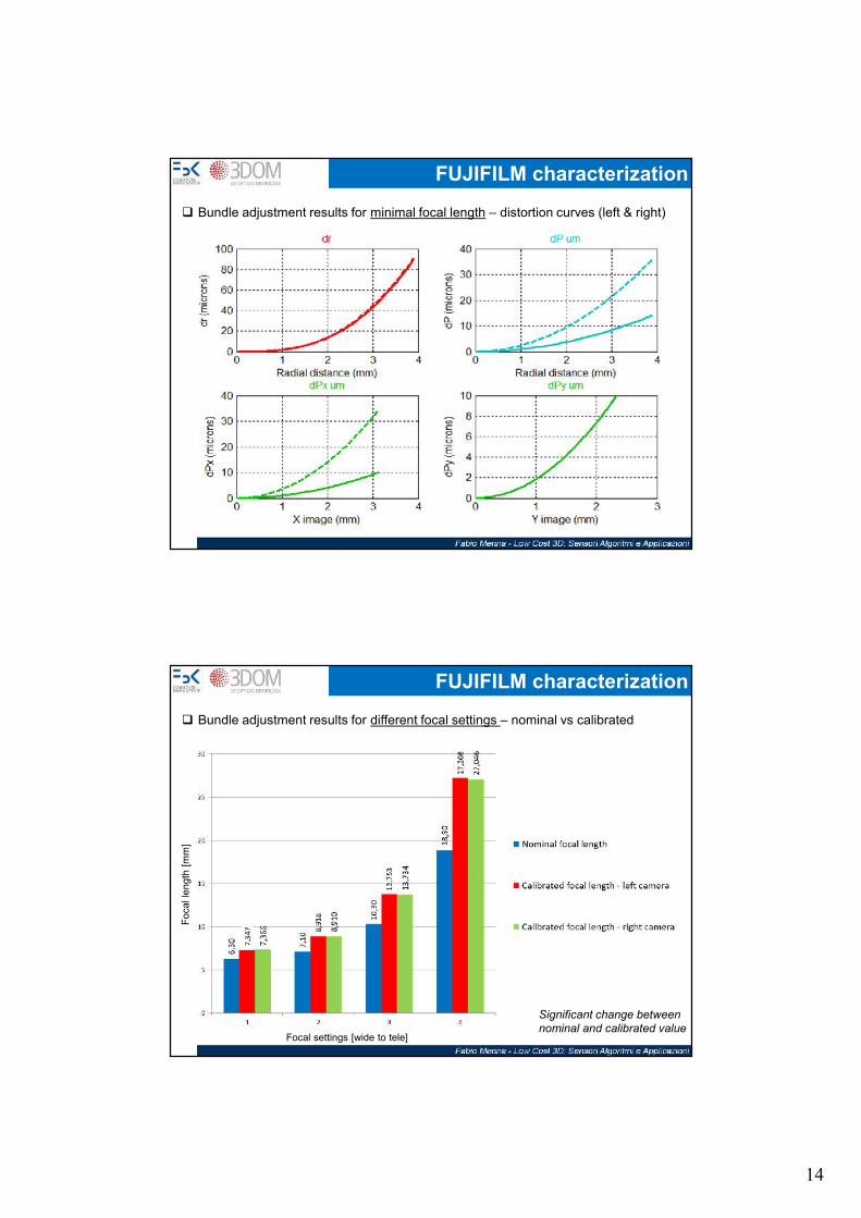
Bundle adjustment results for minimal focal length – distortion curves (left & right)
FUJIFILM characterization
Bundle adjustment results for different focal settings – nominal vs calibrated
Foca
l len
gth
[mm
]
Focal settings [wide to tele]
Significant change betweennominal and calibrated value

15
FUJIFILM characterization Bundle adjustment results for different focal settings – distortion curves
Focal length = 8.9 mmFocal length = 13 mm
Focal length = 27.2 mm
- Similar behavior for radial curves of left and right camera- Different behavior for the tangential distortions- At minimal zoom radial distortion is up to 80 microns
FUJIFILM characterization Bundle adjustment results for different focal settings – principal point and baseline behavior
-0,8
-0,6
-0,4
-0,2
0
0,2
0,4
0,6
6,3 7,1 10,3 18,9
x0_left
x0_right
y0_left
y0_right
Focal length [mm]
Focal length [mm]
Average baseline Standard_deviation: 0.25mm

16
FUJIFILM characterization Bundle adjustment results for different focal settings – Affinity factor
1.680
1.685
1.690
1.695
1.700
1.705
1.710
1.715
1.720
1.725
6.3 7.1 10.3 18.9
pixel_size_x_left
pixel_size_x_right
Focal length [mm]
- Nominal pixel size: 1.7 micron- Very high residuals without affinity factor Focal length [mm]
Max
imum
affi
nity
cor
rect
ion
[pix
el]
Pix
el s
ize
[mic
ron]
FUJIFILM characterizationACCURACY IN 3D MEASUREMENTS:Comparison with photogrammetry on the 3D calibration frame• A stereo pair taken from a frontal position (1.5m) is used to
forward triangulate the 3D points of the testfield.
• COMPARISONS:• IO and EO from a self calibration using only the single pair
scale from MPO tag• IO from EXIF, relative orientation, scaling from MPO tag• IO and mean EO from the bundle adjustment with self cal• IO from EXIF, relative orientation, scaling on the object• IO from bundle adj, EO from relative orientation, scale from
mean baseline• IO and mean EO from the bundle adjustment with self cal (3
months before)
17
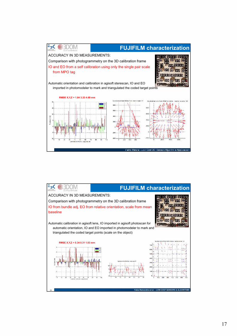
FUJIFILM characterizationACCURACY IN 3D MEASUREMENTS:Comparison with photogrammetry on the 3D calibration frameIO and EO from a self calibration using only the single pair scale
from MPO tag
Automatic orientation and calibration in agisoft sterescan, IO and EOimported in photomodeler to mark and triangulated the coded target points
RMSE X,Y,Z = 1.84 3.33 4.69 mm
Fabio Remondino et al. – LOW-COST SENSORS & ALGORITHMS34
FUJIFILM characterizationACCURACY IN 3D MEASUREMENTS:Comparison with photogrammetry on the 3D calibration frameIO from bundle adj, EO from relative orientation, scale from meanbaseline
Automatic calibration in agisoft lens, IO imported in agisoft photoscan forautomatic orientation, IO and EO imported in photomodeler to mark andtriangulated the coded target points (scale on the object)
RMSE X,Y,Z = 0.34 0.31 1.03 mm

18
Fujifilm at ca 50cm (pattern projection) NEXTENGINE (accuracy σz≈0.3 mm)
1 M polygons 1.6M polygons
FUJIFILM characterization
- 31 stereo-pairs oriented and matched (2.5 Mil. points)- Fuji point clouds registration / alignment- NextEngine 3D laser scanner used as reference- Comparison after ICP alignment of the 2 datasets (std = 0.35 mm)
PERFORMANCES IN 3D MODELLING:3D comparison on a small statue (white matte plastic, ca 35 cm height and 20 cm wide)
FUJIFILM characterizationPERFORMANCES IN 3D MODELLING:
- Geometric differences follows a Gaussian (std = 0.35 mm)
19
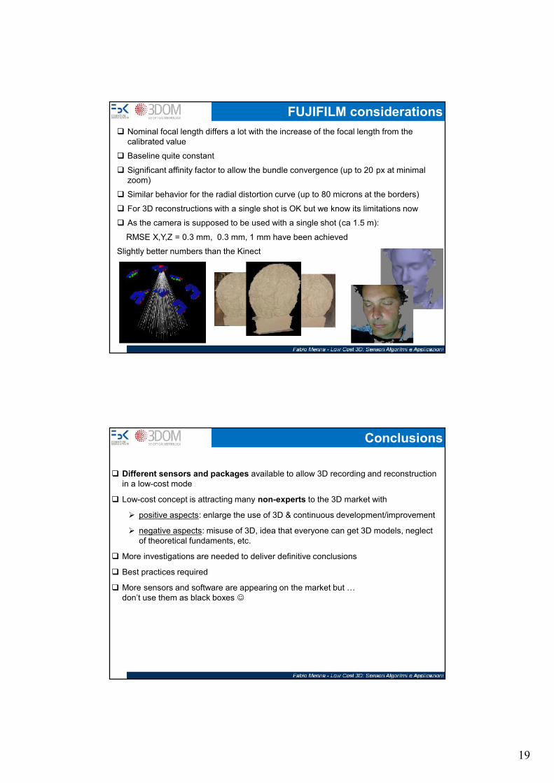
FUJIFILM considerations Nominal focal length differs a lot with the increase of the focal length from the
calibrated value
Baseline quite constant
Significant affinity factor to allow the bundle convergence (up to 20 px at minimalzoom)
Similar behavior for the radial distortion curve (up to 80 microns at the borders)
For 3D reconstructions with a single shot is OK but we know its limitations now
As the camera is supposed to be used with a single shot (ca 1.5 m):
RMSE X,Y,Z = 0.3 mm, 0.3 mm, 1 mm have been achieved
Slightly better numbers than the Kinect
Conclusions
Different sensors and packages available to allow 3D recording and reconstructionin a low-cost mode
Low-cost concept is attracting many non-experts to the 3D market with
positive aspects: enlarge the use of 3D & continuous development/improvement
negative aspects: misuse of 3D, idea that everyone can get 3D models, neglectof theoretical fundaments, etc.
More investigations are needed to deliver definitive conclusions
Best practices required
More sensors and software are appearing on the market but …don’t use them as black boxes


![Samsung Ln26-32c350d1dxza b360c5dxza b350f1dxza Ch Lc3d Training-manual [ET]](https://static.fdocuments.in/doc/165x107/54fd68ca4a7959fc798b45ff/samsung-ln26-32c350d1dxza-b360c5dxza-b350f1dxza-ch-lc3d-training-manual-et.jpg)