CAR PARK GATE CONTROL SYSTEM USING PIC...
24
CAR PARK GATE CONTROL SYSTEM USING PIC MICROCONTROLLER KARIMAH BINTI AWANG MAN This Report Is Submitted In Partial Fulfillment of Requirements for the Degree of Bachelor in Electrical Engineering (Control, Instrumentation, and Automation) Fakulti Kejuruteraan Elektrik Univesiti Teknikal Malaysia Melaka May 2008
-
Upload
nguyenkhuong -
Category
Documents
-
view
214 -
download
0
Transcript of CAR PARK GATE CONTROL SYSTEM USING PIC...
CAR PARK GATE CONTROL SYSTEM USING PIC MICROCONTROLLER
KARIMAH BINTI AWANG MAN
This Report Is Submitted In Partial Fulfillment of Requirements for the Degree of
Bachelor in Electrical Engineering (Control, Instrumentation, and Automation)
Fakulti Kejuruteraan Elektrik
Univesiti Teknikal Malaysia Melaka
May 2008
“I hereby declared that I have read through this report and found that it has comply
the partial fulfillment for awarding the degree of Bachelor of Electrical Engineering
(Control, Instrumentation, and Automation)
Signature :………………………………………………
Supervisor’s name :………………………………………………
Date :……………………………………………….

ii
“I hereby declared that this report is a result of my own work except for the excerpts that
have been cited clearly in the references.”
Signature :………………………………………………………
Name : KARIMAH BINTI AWANG MAN
Date : ………………………………………………………

iii
ACKNOWLEDGEMENT
First of all, I would like to take the opportunity to express my appreciation to all
those who have helped me in making this report successfully.
My special thanks to my supportive supervisor, Mr Muhammad Nizam bin
Kamarudin for his patience and guidance to make me understand about the project.
Secondly, I would like to say thank you to all the UTeM lecturers for their
support and guidance by providing the facilities in order to make me convenient to
complete the project. I would like also to thank the technical staff for their co-operation.
Lastly, I would like to thank to my friends and family who have supporting me
during this project.

iv
ABSTRACT
This project is to present a real time car park control system using Peripheral
Interface Controller (PIC) microcontroller as controller. The system allowed car to enter
or exit from the parking lot. The security design is fully automated system and easy to
operate and troubleshoot. This car park system allows a certain number of car parking
lots. When a car comes in, the sensor will detect and close the contact. Then, the sensor
will gives signal to motor or relay to run. The motor will generate current to open the
gate and allowed car enters the parking lots. After the car in, the gate will automatically
close. Lastly, the counter will start count and display the number of car lots available.
Although, the led will display if the parking lots are full and not allow any car in. The
same process is applied to car out area (exit). The counter will decrease after there is a
car move out of area.

v
ABSTRAK
Project ini menggantikan satu sistem kawalan tempat letak kereta menggunakan
pengawal mikro PIC sebagai pengawal Sistem ini digunakan untuk membenarkan kereta
untuk masuk atau keluar dari tempat letak kereta. Rekabentuk keselamatan ini adalah
sistem automatik sepenuhnya dan senang untuk beroperasi dan baikpulih sistem. Sistem
tempat letak kereta ini membenarkan jumlah lot kereta yang ditetapkan. Apabila sebuah
kereta masuk, pengesan akan mengesan dan menutup kontak. Kemudian, pengesan akan
menghantar isyarat kepada motor ataupun relay untuk berkerja. Motor ini akan
menghasilkan arus untuk membuka palang supaya kereta dibenarkan masuk kedalam
tempat letak kereta. Selepas kereta masuk, palang akan tertutup secara automatik. Akhir
sekali, pembilang akan mula membilang dan memaparkan jumlah tempat letak kereta
yang masih ada. Walau bagaimanapun, led akan menyala sekiranya tempat letak penuh
dan tidak akan membenarkan kereta lain masuk kedalam tempat letak kereta. Proses
yang sama digunakan untuk keluar kawasan. Pembilang akan menolak satu selepas
terdapat sebuah kereta meninggalkan kawasan.
vi
TABLE OF CONTENTS
CHAPTER CONTENTS PAGE
PROJECT TITLE i
RECOGNITION ii
ACKNOWLEDGEMENT iii
ABSTRACT iv
TABLE OF CONTENTS vi
LIST OF TABLES x
LIST OF FIGURES xi
LIST OF APPENDIX xiii
LIST OF ABBREVIATION xiv
1 INTRODUCTION 1
1.0 Introduction 1
1.1 Project Objectives 2
1.2 Project Statements 2
1.3 Project Scope 2
2 LITERATURE REVIEW 3
2.0 Introduction 3
2.1 Review of the car park system
product-AMTEL 3
2.1.1 Ticket Dispenser and entry
lane control tower 4
2.1.2 RF-ID reader 5
2.1.3 Barrier gates 5
2.1.4 Lot Full system 6
vii
2.2 Microcontroller 6
2.2.1 PIC16F877A 7
2.2.1.1 Memory 9
2.2.1.2 Peripherals 11
2.2.1.3 Power Supply 14
2.2.1.4 Oscillator 14
2.3 MicroC Software 16
2.3.1 A Guide to Programming
Using MicroC Software 17
2.3.2 JDM Programmer 19
2.4 Software 20
2.5 Sensor 20
2.5.1 Infra-Red sensor 21
2.6 Power Supply 22
2.7 Servo Motor 22
2.8 Voltage regulation 24
3 THEORY AND BACKGROUND 25
3.0 Research and analysis parking
system at Malacca 25
3.1 Project design 26
3.2 Hardware development 27
3.3 Software Development 29
3.4 Finalizing 30
4 METHODOLOGY 31
4.0 Project Planning 31
4.1 Literature review 33
4.2 Project design 33

viii
4.2.1 Car Park 34
4.2.2 Infrared Sensor 34
4.2.3 PIC 35
4.2.4 Servo Motor 35
4.2.5 Counter 36
4.3 Finalizing 36
4.3.1 Troubleshoot 37
4.4 Project planning 38
5 ANALYSIS AND RESULT 39
5.0 Overview 39
5.1 Hardware development 39
5.1.1 Servo motor 40
5.1.2 PIC16F877A 42
5.1.3 Power Supply 43
5.1.4 Infrared Sensor 44
5.1.5 Universal Synchronous
Asynchronous Receiver
Transmitter (USART) 47
5.1.6 Counter 48
5.1.7 The Car Park Gate Model 49
5.2 Software development 50
5.2.1 Pulse Width Modulation
(PWM) 51
5.2.2 Main Program 52
5.2.3 Car Park System Programming 54
6 DISCUSSION AND SUGGESTION 57
6.0 Discussion 57
6.1 Recommendation 58
ix
7 CONCLUSION 59
REFERENCES 60
APPENDIX A PIC 16F877A DATASHEET 61
APPENDIX B CD4026BE DATASHEET 67
APPENDIX C SERVO MOTOR 69
APPENDIX D DEVELOPMENT KITS FOR PIC16F877A 71

x
LIST OF TABLES
NO TITLE PAGE
2.1 Capacitor selection for ceramic resonator 15
2.2 Capacitor selection for Crystal oscillator 16
4.1 Gantt-chart project planning 38
5.1 PIC16F877A Set pins 43
5.2 Output voltage for IR sensor 45
5.3 Input and Output truth table 49
5.4 Counter UP/DOWN 50
xi
LIST OF FIGURES
NO TITLE PAGE
2.1 The car park system 4
2.2 Barrier gates 5
2.3 PIC16F877A Pin out Diagram 9
2.4 Program Memory block 10
2.5 Timer0 block diagram 13
2.6 Timer1 block diagram 13
2.7 Timer2 block diagram 14
2.8 Crystal or ceramic resonator operation 15
2.9 MicroC software 17
2.10 New project dialog 18
2.11 Edit project dialog 18
2.12 Built project dialog 19
2.13 PIC16F877A and JDM multilink connection 20
2.14 IR Sensor 21
2.15 Function of IR 22
2.16 Duration of Pulse Width Signal 23
2.17 Servos Turn Rate 24
3.1 Malacca Central car parking system 25
3.2 Malacca Bazaar car parking system 26
3.3 Car park model 27
3.4 Car park control System Chart 28
3.5 Program to set I/O port 29
3.6 Interfacing with computer 30

xii
4.1 Project Methodology 32
4.2 Methodology for car park 34
4.3 Methodology for Infrared Sensor 34
4.4 Methodology for PIC circuit 35
4.5 Methodology for Servo 35
4.6 Methodology for Counter 36
4.7 Methodology for troubleshoot 37
5.1 Hardware design in Proteus 40
5.2 Servo motor wire configuration 40
5.3 DC servo motor 41
5.4 Servo motor in simulation 42
5.5 Power Supply circuit 43
5.6 Power supply for car park model 44
5.7 Sensor circuit 45
5.8 IR sensor circuit 46
5.9 USART terminal in Proteus 47
5.10 Counter circuit in Proteus 48
5.11 Counter circuit common cathode 49
5.12 Main program to set up I/O pins 50
5.13 Pulse Width Modulation analyses for Servo Motor 51
5.14 Wiring in Proteus 53

xiii
LIST OF APPENDIX
NO TITLE PAGE
A PIC 16F877A DATASHEET 61
B CD4026BE DATASHEET 67
C SERVO MOTOR 69
D DEVELOPMENT KITS FOR PIC16F877A 71
xiv
LIST OF ABBREVIATION
PIC PERIPHERAL INTERFACE CONTROLLER
PLC PROGRAMMABLE LOGIC CONTROLLER

1
CHAPTER 1
INTRODUCTION
1.0 Introduction
The aim of this project is to present a real time car park control system using
PIC to control the parking area. The automated car park control system using PIC as
programming tool to run the whole operation. The automatic car park control system
will help to reduce the cost in terms of requirement such as job opportunity and
increase security. Moreover, this system also is faster flexible and approximately to
market needs.
The purposed automated car park control system allows a number of cars to
be parked. The amount cars, which are authorized to park, will be decided according
to customer requirement. For an example, the parking lot requirements in private
area such as apartments are fixed to authorize only. The amount of cars can be
control by the proposed system.
The car park control system works when there is a car comes in or out. When
a car enters the parking area, a sensor will detect the incoming car and send signal to
PIC. After that, PIC will receive the signal and gives order to the counter, which is
related to PIC to increase the number of cars display. Meanwhile, the motor will
energized and allow the car to enter the parking lot. The same process will be used
when a car goes out of the parking area. But, for this step, the counter will decrease
the number of cars display. Although, when the parking lot become full and cannot
receive anymore car, the led will display as the lot is full to inform the customers that
there is no more empty space lot.
2
1.1 Project Objectives
The objectives of the project proposal;
1. To develop a model of car park control system using PIC controller.
2. To interface the model with computer programmer in order to get signal
for a real time car park control system.
1.2 Problem Statements
The problem statements are;
1. The car park control system can function automatically because there is
sensor to detect when cars authorize and can reduce manpower.
2. It is easier to know if the car park full or not through a counter display
at the same time.
3. The current car park system is not user friendly.
1.3 Project Scope
The scope of work for this project is divided into two parts; the hardware and
the software are;
1. Using MicroC software to write the program for PIC16F877A
2. Electronic components were used at the end of this project.
3. Seven segments are used as counter in the project design and
application.
4. The mechanical part involves the motor drive system, the sensor layout,
and FULL display

3
CHAPTER 2
LITERATURE REVIEW
2.0 Introduction
This chapter will discuss about the overall theories and works of the
project. It also reviews selected tools used in the project. The full
understanding of the theory is very important as a guideline.
2.1 Review of the car park system product-AMTEL
AMTEL is one of parking system product. AMTEL offers complete
solutions for parking and revenue control that can work integrate with Access
Control, Visitor Processing and other system required in any medium to large
complex. It offer multiple solutions for handling “monthly” (regular) as well
as “Transient” (short term) parking patrons and with TCP/IP connectivity for
all components, integration with existing LAN/WAN infrastructure is
assured. The AMTEL parking system consists of Ticket Dispenser, entry lane
and exit lane, Proximity card reader, RFID readers, Barrier gates, „LOT
FULL‟ display and Parking & revenue control software.

4
Figure 2.1: The car park system
2.1.1 Ticket Dispenser and entry lane control tower.
Ticket dispenser tower is designed to provide all the features that
maybe needed for control the lane.
1. Ticket Dispenser can print a ticket with the data, time, lane, ticket, etc.
in regular print as well as bar-code formats. This ticket can be issued
automatically or as soon as the flashing “Touch-for-ticket” button is
used.
2. Card reader can read the access card of monthly parker.
3. Back-lit LCD Display a large character, 4 line LCD display provides
user instructions in up to two languages at every step of the
transaction.
4. Intercom most tower include one of the following two forms of
intercoms;
a. Hardwired Intercom station that is connected to a master
station located nearby in the building.
b. Telephone Intercom that automatically dials a number and gets
assistance from the person on that number. This is idea where
the Help is coming from a remote location or form a guard
who is carrying a cell-phone while on roving patron on the
premises.
5
2.1.2 RF-ID reader
An RFID system consists of two major components- a reader and a
tag. They work together to provide a non-contact solution to uniquely identify
people, objects or vehicles. RFID does not require line of sight between the
tag and the reader and works effectively in dirty environment.
The reader consists of an antenna, a RF receiver and processing
circuitry. The antenna couples the electromagnetic energy transmitted by the
Tag to the Reader. The processing circuitry of the reader decodes the received
information and sends the data to a Host Computer or a control Device/
panel. The reader reads ranges could be programmed using dedicated
software.
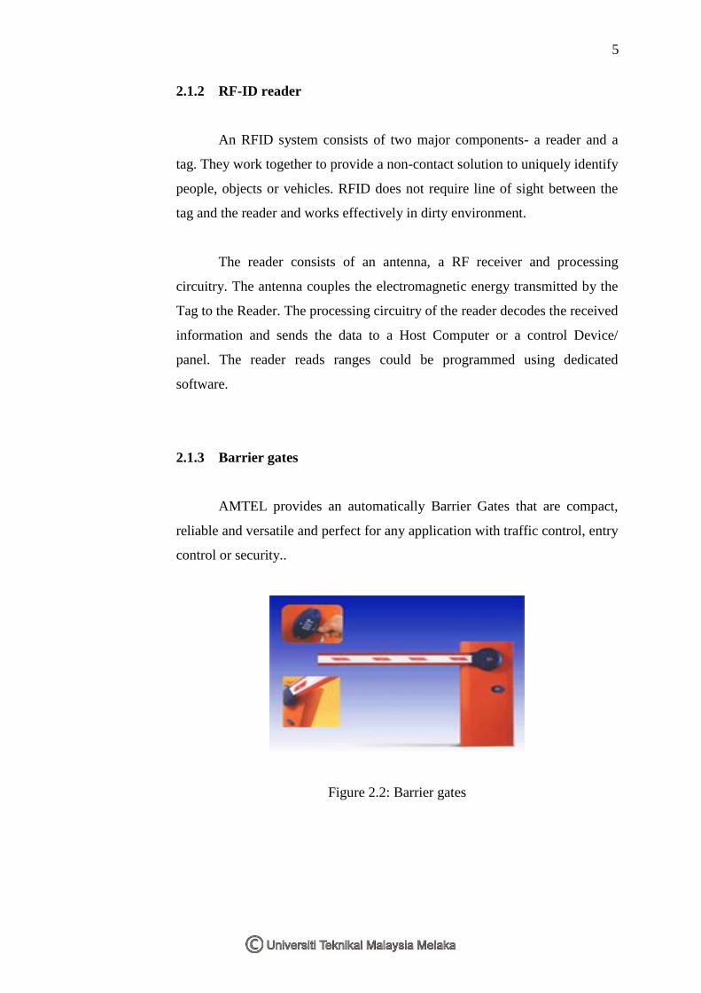
2.1.3 Barrier gates
AMTEL provides an automatically Barrier Gates that are compact,
reliable and versatile and perfect for any application with traffic control, entry
control or security..
Figure 2.2: Barrier gates

6
2.1.4 Lot Full system
The entry lane and exit lane consist a lot “FULL”. Each tower is
capable of tracking all the vehicles passing through their lane. This data is
passed on the Capacity Control Program in the server PC which controls Lot
Full systems.
AMTEL has four different types of Lot Full Control. The types are
Lot Full count for Monthly patrons only, Lot Full count for Transient patrons,
Lot Full count for total garage or lot, and Lot Full count for a “specific”
customer.
The Lot Full count for Monthly patrons: the system tracks only the
monthly cardholders and turns off entry for the cardholders if their capacity is
used up. Lot Full count for Transient patrons: the most common approach,
where a certain capacity is reserved for transient patrons and the Lot Full sigh
in activated when this capacity reaches zero.
Lot Full count for total garage or lot: under this system, the total
capacity of the lot/garage is monitored. Lot Full count for a “specific”
customer: this system only has fixed number of customers. It will not allow
next customer.
2.2 Microcontroller
Microcontroller had beginnings in the development of technology of
the integrated circuits. This development has made it possible to store
hundreds of thousands of transistor into one chip. These integrated circuits
contained both processor and peripherals. This chip is called as
microcomputer or later it would be known as microcontroller. It includes
input and output ports, memory, timer and etc.
7
The main reason to use microcontroller is the cost and easy to get.
Even though it has various applications, the price is more cheaply compared
to complex circuit such as IC MC14528B.
The second reason is its ability to re-program. User can program
microcontroller to apply in their project. They are also can simply change the
program they made.
Other than that, microcontroller also can operate logic and
mathematic. This is important operation in any project development. It can
use for logic program to convert analog input to digital (ADC) signal.
Lastly is its ability to programmed in various type of software
language such as C++, C, basic pro, assembly language, and any other
language that make this microcontroller known as user friendly.
There is a lot of company that produced microcontroller such as
Atmel (Attiny II), Microchip (PIC16CR509A), Motorola (68HC705KJI) and
etc.
The controller will works as the brain of system that will do all the
logic for system. It will interpret the output of sensor and control the drive
system. All these tasks will be complete by programming the controller. In
this project, PIC16F877A microcontroller will be use.
2.2.1 PIC16F877A
Microchip technology has series of microcontroller called PIC in
purpose of better application and low cost. PIC usually assumed as an
interface control between hardware and software. With this device, circuit
efficiency problem can easily solve compared to its application that
commonly easier to be influenced by temperature and noise factor.
8
There are two types of PIC series, flash (F) and eeprom (C). The
series such as 12C5XX, 16C62X, 16F8XX, and the latest is 18CXXX. Each
type has various function and criteria such as number of input and output,
memory, and etc.
PIC16F877A is a microcontroller that used in car park control system.
PIC16F877A unit is 8-bit devices composed of standard on-chip peripherals
including 368 bytes of Data Memory (Ram), 256 bytes of Eeprom Data
Memory, 14-bit wide instruction words and also have 15 interrupt sources
such as RB0/INT, and etc.
The peripheral features including Timer0: 8-bit timer/ counter with 8-
bit prescaler, Timer1: 16-bit timer/ counter with prescaler, can be
incremented during Sleep via external crystal/clock, Timer2: 8-bit timer/
counter with 8-bit period register, prescaler and postcaler, Two capture,
compare and PWM modules: capture is 16-bit, max. resolution is 12.5 ns,
compare is 16-bit, max. resolution is 200ns and PWM max resolution is 10-
bit. Other peripherals are Synchronous Serial Port (SSP) with master mode
and master/ slave, Universal Synchronous Asynchronous Receiver
Transmitter (USART/ SCI) with 9-bit address detection, Parallel Slave Port
(PSP): 8-bits wide with external RD, WR, and CS controls, and Brown-out
detection circuitry for Brown-out Reset (BOR).
The analog features has 10-bit, up to 8-channel Analog-to-digital
Converter (ADC), Brown-out Reset (BOR), Analog Comparator module; two
analog comparators, Programmable on-chip voltage reference (VREF)
module, and Programmable input multiplexing from device inputs and
internal voltage reference. Meanwhile the comparator outputs are externally
accessible.
9
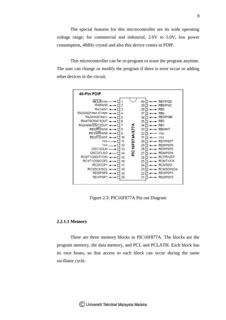
The special features for this microcontroller are its wide operating
voltage range; for commercial and industrial, 2.0V to 5.0V, low power
consumption, 4MHz crystal and also this device comes in PDIP.
This microcontroller can be re-program or erase the program anytime.
The user can change or modify the program if there is error occur or adding
other devices in the circuit.
Figure 2.3: PIC16F877A Pin out Diagram
2.2.1.1 Memory
There are three memory blocks in PIC16F877A. The blocks are the
program memory, the data memory, and PCL and PCLATH. Each block has
its own buses, so that access to each block can occur during the same
oscillator cycle.