CAPTURE REGION ANALYSIS FOR MISSILE GUIDANCE WITH … · characteristics of look-angle constraint...
9
1 Abstract A capture region for missile guidance laws under field-of-view constraint is analyzed. To make a missile intercept a non-maneuvering target, physical constraints including seeker`s field-of-view and acceleration limit should be considered, because these constraints may restrict maneuver of the interceptor. The characteristics of look-angle constraint guidance laws is studied, and feasible trajectory envelope and achievable impact angle set are derived using deviated pursuit trajectory. To validate the analysis of the capture region, numerical simulation is carried out. 1 Introduction Strapdown-seeker system has several advantages over gimbal-seeker system because of its simple mechanic structure, low-cost, and light weight. For these reasons, the strapdown- seeker system has been widely utilized in guided weapons including guided projectiles, kill vehicles, and missiles. For missiles equipped with strapdown-seeker, maintaining lock-on is crucial because a target information is directly obtained from the seeker. The seeker is attached to the missile body and the FOV (Field-of-View) of the seeker is limited, and therefore the missile maneuver and its reachable trajectory may be restricted. Usually, missile with a strapdown-seeker requires a guidance law that can maintain lock-on condition and also satisfy terminal homing objectives. To design guidance law for a missile considering FOV limit, two-stage guidance law [1-3], optimal guidance law [4], biased proportional navigation guidance [5], and hybrid guidance scheme [6] have been proposed. Most of the previous studies, however, focused on stationary target interception [1-5], or slow- moving target interception with wide FOV limit. [6,7] The objective of this study is to find a necessary condition for capture region of the look-angle constraint guidance laws. First, the property of the look-angle constraint guidance law is analyzed where the maximum maneuver of the missile is restricted to maintain the lock- on condition. Then, a feasible trajectory envelope is derived from the pursuit trajectory. Based on the obtained envelope boundary, qualitative behavior of the maximum trajectory is analyzed for tail-chase and head-on engagement cases. The impact angle set can be determined, and necessary condition for the capturable region is examined. To demonstrate the analysis result using the capture region, numerical simulations are performed. This paper is organized as follows. Section 2 presents the problem formulation and characteristics of look-angle constraint guidance. Section 3 provides the capture region analysis. Numerical simulation results are shown in Sec. 4, Finally, conclusion is given in Sec. 5. 2 Problem formulation 2.1 Engagement Kinematics CAPTURE REGION ANALYSIS FOR MISSILE GUIDANCE WITH FIELD-OF-VIEW CONSTRAINT AGAINST MOVING TARGET Seokwon Lee *, Youdan Kim*, and Tae-Yoon Um** *Department of Mechanical and Aerospace Engineering, Seoul National University, Seoul, 151-742, Republic of Korea **Agency for Defense Development, Daejeon 305-600, Republic of Korea Keywords: FOV (Field-of View), Missile Guidance, Strapdown seeker
Transcript of CAPTURE REGION ANALYSIS FOR MISSILE GUIDANCE WITH … · characteristics of look-angle constraint...
1
Abstract
A capture region for missile guidance laws
under field-of-view constraint is analyzed. To
make a missile intercept a non-maneuvering
target, physical constraints including seeker`s
field-of-view and acceleration limit should be
considered, because these constraints may
restrict maneuver of the interceptor. The
characteristics of look-angle constraint
guidance laws is studied, and feasible trajectory
envelope and achievable impact angle set are
derived using deviated pursuit trajectory. To
validate the analysis of the capture region,
numerical simulation is carried out.
1 Introduction
Strapdown-seeker system has several
advantages over gimbal-seeker system because
of its simple mechanic structure, low-cost, and
light weight. For these reasons, the strapdown-
seeker system has been widely utilized in
guided weapons including guided projectiles,
kill vehicles, and missiles.
For missiles equipped with strapdown-seeker,
maintaining lock-on is crucial because a target
information is directly obtained from the seeker.
The seeker is attached to the missile body and
the FOV (Field-of-View) of the seeker is limited,
and therefore the missile maneuver and its
reachable trajectory may be restricted. Usually,
missile with a strapdown-seeker requires a
guidance law that can maintain lock-on
condition and also satisfy terminal homing
objectives. To design guidance law for a missile
considering FOV limit, two-stage guidance law
[1-3], optimal guidance law [4], biased
proportional navigation guidance [5], and
hybrid guidance scheme [6] have been proposed.
Most of the previous studies, however, focused
on stationary target interception [1-5], or slow-
moving target interception with wide FOV limit.
[6,7]
The objective of this study is to find a
necessary condition for capture region of the
look-angle constraint guidance laws. First, the
property of the look-angle constraint guidance
law is analyzed where the maximum maneuver
of the missile is restricted to maintain the lock-
on condition. Then, a feasible trajectory
envelope is derived from the pursuit trajectory.
Based on the obtained envelope boundary,
qualitative behavior of the maximum trajectory
is analyzed for tail-chase and head-on
engagement cases. The impact angle set can be
determined, and necessary condition for the
capturable region is examined. To demonstrate
the analysis result using the capture region,
numerical simulations are performed.
This paper is organized as follows. Section 2
presents the problem formulation and
characteristics of look-angle constraint guidance.
Section 3 provides the capture region analysis.
Numerical simulation results are shown in Sec.
4, Finally, conclusion is given in Sec. 5.
2 Problem formulation
2.1 Engagement Kinematics
CAPTURE REGION ANALYSIS FOR MISSILE GUIDANCE WITH FIELD-OF-VIEW CONSTRAINT
AGAINST MOVING TARGET
Seokwon Lee *, Youdan Kim*, and Tae-Yoon Um**
*Department of Mechanical and Aerospace Engineering, Seoul National University, Seoul,
151-742, Republic of Korea
**Agency for Defense Development, Daejeon 305-600, Republic of Korea
Keywords: FOV (Field-of View), Missile Guidance, Strapdown seeker
S. Lee, Y. Kim, and T. Um
2
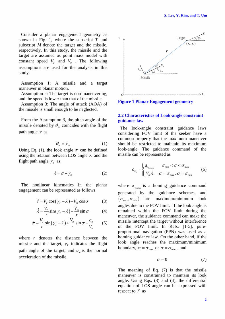
Consider a planar engagement geometry as
shown in Fig. 1, where the subscript T and
subscript M denote the target and the missile,
respectively. In this study, the missile and the
target are assumed as point mass model with
constant speed TV and mV . The following
assumptions are used for the analysis in this
study.
Assumption 1: A missile and a target
maneuver in planar motion.
Assumption 2: The target is non-maneuvering,
and the speed is lower than that of the missile.
Assumption 3: The angle of attack (AOA) of
the missile is small enough to be neglected.
From the Assumption 3, the pitch angle of the
missile denoted by m coincides with the flight
path angle as
m m (1)
Using Eq. (1), the look angle can be defined
using the relation between LOS angle and the
flight path angle m as
m (2)
The nonlinear kinematics in the planar
engagement can be represented as follows
cos cosT T mr V V (3)
sin sinmTT
VV
r r (4)
sin sinm mTT
m
V aV
r r V (5)
where r denotes the distance between the
missile and the target, T indicates the flight
path angle of the target, and ma is the normal
acceleration of the missile.
ma
r
,T Tx z
Missile
Target T
O IX
IY
TV
mV
m
Figure 1 Planar Engagement geometry
2.2 Characteristics of Look-angle constraint
guidance law
The look-angle constraint guidance laws
considering FOV limit of the seeker have a
common property that the maximum maneuver
should be restricted to maintain its maximum
look-angle. The guidance command of the
missile can be represented as
homing min max
max min,c
c
m
m
aa
V
(6)
where homingca is a homing guidance command
generated by the guidance schemes, and
max min, are maximum/minimum look
angles due to the FOV limit. If the look angle is
remained within the FOV limit during the
maneuver, the guidance command can make the
missile intercept the target without interference
of the FOV limit. In Refs. [1-5], pure-
proportional navigation (PPN) was used as a
homing guidance law. On the other hand, if the
look angle reaches the maximum/minimum
boundary, max or min , and
0 (7)
The meaning of Eq. (7) is that the missile
maneuver is constrained to maintain its look
angle. Using Eqs. (3) and (4), the differential
equation of LOS angle can be expressed with
respect to r as
3
CAPTURE REGION ANALYSIS FOR MISSILE GUIDNACE WITH
FIELD-OF-VIEW CONSTRAINT AGAINST MOVING TARGET
max
max
cos cos
sin sin
T T m
T T m
V Vdrd
r V V
(8)
Since (0)T T for a non-maneuvering target
and max , Eq. (8) is equivalent to the
ordinary differential equation of the deviated
pursuit guidance trajectory. Integrating by part
gives the analytic solution of the trajectory as
0
0 max
0
max
max
max
sin sin
sin sin
cosexp
sin sin
T T m
T T m
m
T T m
V Vr r
V V
Vd
V V
(9)
The closed-form solution of the
0
max
max
cos
sin sin
m
T T m
Vd
V V
in Eq. (9) are
different according to the speed ratio
( /T mV V ) as well as FOV limit max . By
defining a parameter max/ sina , the
analytic solution can be obtained as
0
0
max
max
1max
2 2
1
cos
sin sin
tan2cot 2
tan1 1
m
T T m
T
for a
Vd
V V
a
a a
(10)
0
0
max
max
1max
2 2
1
cos
sin sin
tan2cot 2
tanh1 1
m
T T m
T
for a
Vd
V V
a
a a
(11)
From Eqs. (9)-(11), the qualitative behavior of
the solution varies according to the parameter a .
Usually, if the target speed is much slower than
missile speed and FOV limit is large, then 1a .
If FOV is small, on the other hand, the
parameter a becomes greater than unity.
2.3 Maximum acceleration constraint
To reflect the physical constraint of the missile,
the maximum acceleration limit is considered.
As the missile approaches the target while
keeping the look angle within the allowable
limit, the turning rate of the missile reaches its
maximum. When the look angle keeps a
constant 0 , the relation between the maximum
acceleration and LOS rate can be obtained as
maxmax 0
maxmin 0
sin sin
sin sin
mTT
m
mTT
m
V aV
r r V
V aV
r r V
(12)
where max min,a a are the maximum and
minimum accelerations. Because 0,r Eq. (12)
can be expressed as
0
max
sin sin mT T m
Vr V V
a (13)
When the missile reaches its maximum
acceleration, the missile cannot follow the target
due to the maneuverability limit. It causes miss-
distance and fails to lock-on the target. The
maximum acceleration boundary of Eq. (13)
should be used in the capture region analysis.
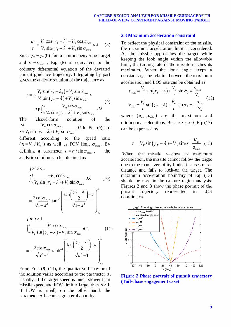
Figures 2 and 3 show the phase portrait of the
pursuit trajectory represented in LOS
coordinates.
Figure 2 Phase portrait of pursuit trajectory
(Tail-chase engagement case)
S. Lee, Y. Kim, and T. Um
4
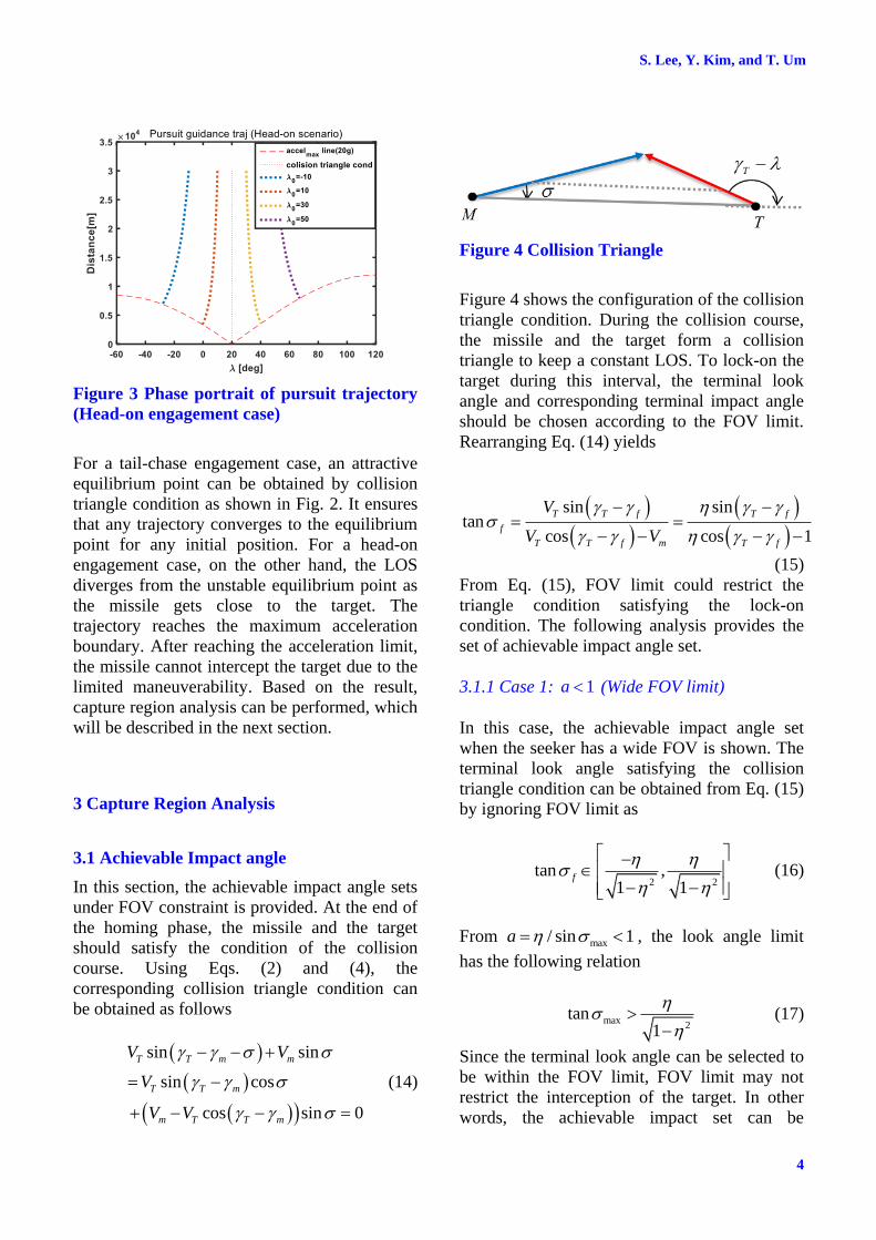
Figure 3 Phase portrait of pursuit trajectory
(Head-on engagement case)
For a tail-chase engagement case, an attractive
equilibrium point can be obtained by collision
triangle condition as shown in Fig. 2. It ensures
that any trajectory converges to the equilibrium
point for any initial position. For a head-on
engagement case, on the other hand, the LOS
diverges from the unstable equilibrium point as
the missile gets close to the target. The
trajectory reaches the maximum acceleration
boundary. After reaching the acceleration limit,
the missile cannot intercept the target due to the
limited maneuverability. Based on the result,
capture region analysis can be performed, which
will be described in the next section.
3 Capture Region Analysis
3.1 Achievable Impact angle
In this section, the achievable impact angle sets
under FOV constraint is provided. At the end of
the homing phase, the missile and the target
should satisfy the condition of the collision
course. Using Eqs. (2) and (4), the
corresponding collision triangle condition can
be obtained as follows
sin sin
sin cos
cos sin 0
T T m m
T T m
m T T m
V V
V
V V
(14)
Figure 4 Collision Triangle
Figure 4 shows the configuration of the collision
triangle condition. During the collision course,
the missile and the target form a collision
triangle to keep a constant LOS. To lock-on the
target during this interval, the terminal look
angle and corresponding terminal impact angle
should be chosen according to the FOV limit.
Rearranging Eq. (14) yields
sin sintan
cos cos 1
T T f T f
f
T T f m T f
V
V V
(15)
From Eq. (15), FOV limit could restrict the
triangle condition satisfying the lock-on
condition. The following analysis provides the
set of achievable impact angle set.
3.1.1 Case 1: 1a (Wide FOV limit)
In this case, the achievable impact angle set
when the seeker has a wide FOV is shown. The
terminal look angle satisfying the collision
triangle condition can be obtained from Eq. (15)
by ignoring FOV limit as
2 2
tan ,1 1
f
(16)
From max/ sin 1a , the look angle limit
has the following relation
max2
tan1
(17)
Since the terminal look angle can be selected to
be within the FOV limit, FOV limit may not
restrict the interception of the target. In other
words, the achievable impact set can be
5
CAPTURE REGION ANALYSIS FOR MISSILE GUIDNACE WITH
FIELD-OF-VIEW CONSTRAINT AGAINST MOVING TARGET
determined by the look-angle constraint-free
guidance law. Using PPN guidance, for example,
the achievable impact set for moving target can
be obtained as ([7])
* 1
0 0sin sinTf f
M
V
V
(18)
where subscript o denotes an initial condition,
and * is given by
* *
0
0*
sintan
cos /
f f
f T MV V N
(19)
Note that if the missile maintains the constant
look-angle, 1
0 max2
tan1
during
the maneuver, then the missile reaches a
maximum acceleration before intercepting the
target.
3.1.2 Case 2: 1a (Narrow FOV limit)
When the FOV limit is narrow so that the
magnitude of the parameter is larger than unity,
i.e., 1a , the FOV limit has the following
inequality.
max2
tan1
(20)
Since the FOV limit does not cover the
achievable terminal look angle set (16), the
achievable terminal look angle set is reduced as
max maxtan tan , tanf (21)
Therefore, the achievable impact angle set
corresponding to the achievable look angle set is
reduced according to the FOV limit. The
following proposition addresses the reduced
impact angle set.
Proposition 1. Suppose that a missile engages a
non-maneuvering target with max/ sin 1a ,
and max max, . Then, achievable impact
angle set is restricted by
* *
min maxfm (22)
where the lower bound and upper bound of the
achievable impact angle set satisfy
*
.
.*
.
sintan
cos 1
f
f
T
T
(23)
where denotes min or max.
3.2 Feasible trajectory analysis
In this section, the allowable capture region is
examined by deriving a feasible trajectory. Note
that the FOV limit does not restrict the
achievable impact angle set when the seeker has
wide FOV. Let us focus our interest on the
small FOV case, i.e., 1a .
Since the maximum maneuver of the missile
can be restricted by the deviated pursuit
trajectory, the qualitative characteristics is
closely related to the pursuit maneuver. Given
initial relative position 0 0,r , the maximum
and minimum trajectory steered by the pursuit
guidance can be obtained using Eqs. (9) and
(10) as
0
0 max
max 0
max
1max
2 2
sin sin
sin sin
tan2cot 2
exp tanh1 1
T T m
T T m
T
V Vr r
V V
a
a a
(24)
0
0 min
min 0
min
1min
2 2
sin sin
sin sin
tan2cot 2
exp tanh1 1
T T m
T T m
T
V Vr r
V V
a
a a
(25)
Thus, the feasible missile trajectory using the
look-angle constraint guidance command can be
bounded by the maximum and minimum
trajectory obtained by Eqs. (24) and (25). Figure
5 shows the feasible trajectory for the tail chase
S. Lee, Y. Kim, and T. Um
6
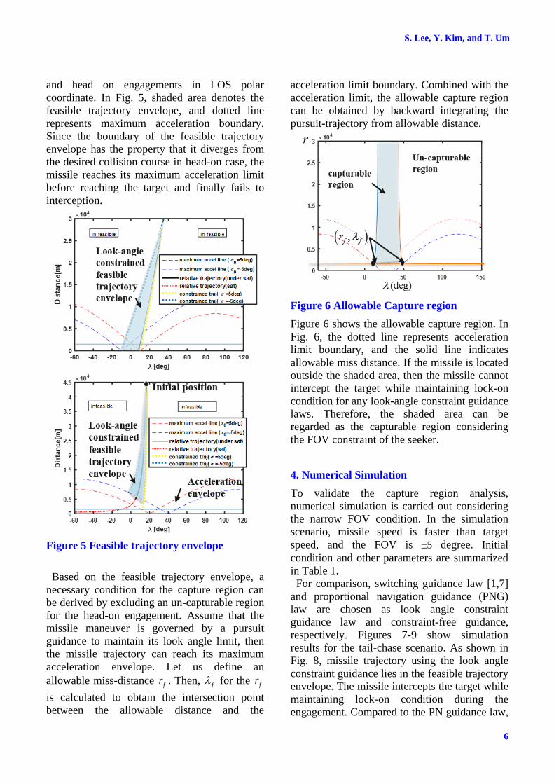
and head on engagements in LOS polar
coordinate. In Fig. 5, shaded area denotes the
feasible trajectory envelope, and dotted line
represents maximum acceleration boundary.
Since the boundary of the feasible trajectory
envelope has the property that it diverges from
the desired collision course in head-on case, the
missile reaches its maximum acceleration limit
before reaching the target and finally fails to
interception.
Figure 5 Feasible trajectory envelope
Based on the feasible trajectory envelope, a
necessary condition for the capture region can
be derived by excluding an un-capturable region
for the head-on engagement. Assume that the
missile maneuver is governed by a pursuit
guidance to maintain its look angle limit, then
the missile trajectory can reach its maximum
acceleration envelope. Let us define an
allowable miss-distance fr . Then, f for the fr
is calculated to obtain the intersection point
between the allowable distance and the
acceleration limit boundary. Combined with the
acceleration limit, the allowable capture region
can be obtained by backward integrating the
pursuit-trajectory from allowable distance.
Figure 6 Allowable Capture region
Figure 6 shows the allowable capture region. In
Fig. 6, the dotted line represents acceleration
limit boundary, and the solid line indicates
allowable miss distance. If the missile is located
outside the shaded area, then the missile cannot
intercept the target while maintaining lock-on
condition for any look-angle constraint guidance
laws. Therefore, the shaded area can be
regarded as the capturable region considering
the FOV constraint of the seeker.
4. Numerical Simulation
To validate the capture region analysis,
numerical simulation is carried out considering
the narrow FOV condition. In the simulation
scenario, missile speed is faster than target
speed, and the FOV is 5 degree. Initial
condition and other parameters are summarized
in Table 1.
For comparison, switching guidance law [1,7]
and proportional navigation guidance (PNG)
law are chosen as look angle constraint
guidance law and constraint-free guidance,
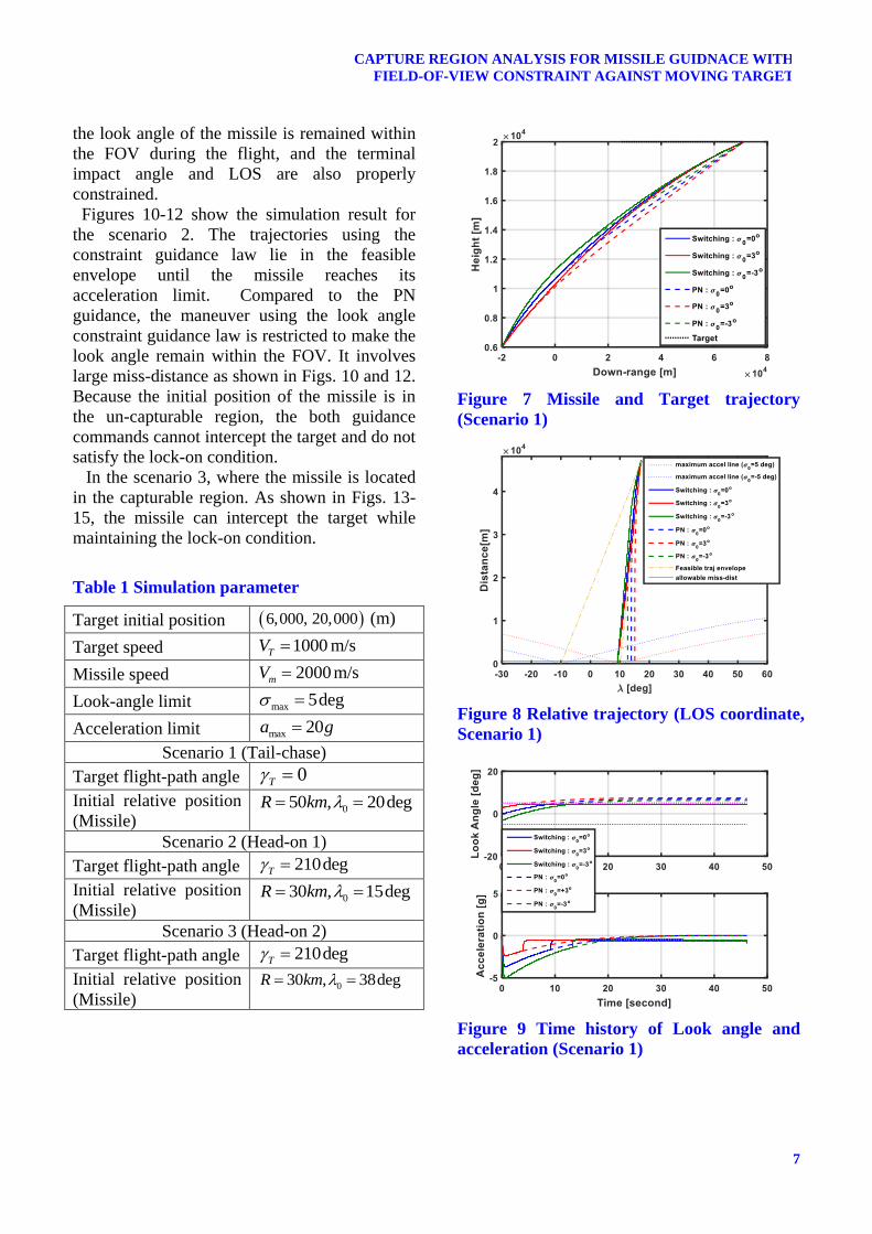
respectively. Figures 7-9 show simulation
results for the tail-chase scenario. As shown in
Fig. 8, missile trajectory using the look angle
constraint guidance lies in the feasible trajectory
envelope. The missile intercepts the target while
maintaining lock-on condition during the
engagement. Compared to the PN guidance law,
7
CAPTURE REGION ANALYSIS FOR MISSILE GUIDNACE WITH
FIELD-OF-VIEW CONSTRAINT AGAINST MOVING TARGET
the look angle of the missile is remained within
the FOV during the flight, and the terminal
impact angle and LOS are also properly
constrained.
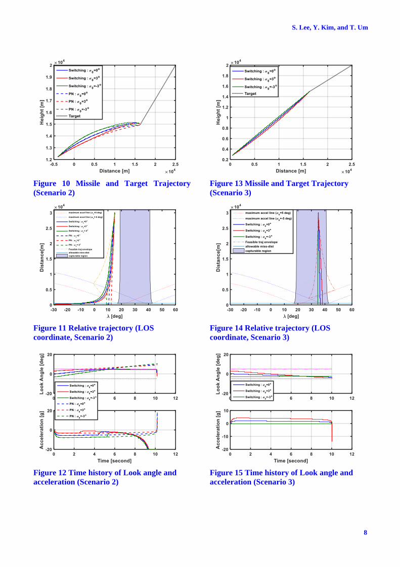
Figures 10-12 show the simulation result for
the scenario 2. The trajectories using the
constraint guidance law lie in the feasible
envelope until the missile reaches its
acceleration limit. Compared to the PN
guidance, the maneuver using the look angle
constraint guidance law is restricted to make the
look angle remain within the FOV. It involves
large miss-distance as shown in Figs. 10 and 12.
Because the initial position of the missile is in
the un-capturable region, the both guidance
commands cannot intercept the target and do not
satisfy the lock-on condition.
In the scenario 3, where the missile is located
in the capturable region. As shown in Figs. 13-
15, the missile can intercept the target while
maintaining the lock-on condition.
Table 1 Simulation parameter
Target initial position 6,000, 20,000 (m)
Target speed 1000TV m/s
Missile speed 2000mV m/s
Look-angle limit max 5deg
Acceleration limit max 20a g
Scenario 1 (Tail-chase)
Target flight-path angle 0T
Initial relative position
(Missile) 050 , 20degR km
Scenario 2 (Head-on 1)
Target flight-path angle 210degT
Initial relative position
(Missile) 030 , 15degR km
Scenario 3 (Head-on 2)
Target flight-path angle 210degT
Initial relative position
(Missile) 030 , 38degR km
Figure 7 Missile and Target trajectory
(Scenario 1)
Figure 8 Relative trajectory (LOS coordinate,
Scenario 1)
Figure 9 Time history of Look angle and
acceleration (Scenario 1)
S. Lee, Y. Kim, and T. Um
8
Figure 10 Missile and Target Trajectory
(Scenario 2)
Figure 11 Relative trajectory (LOS
coordinate, Scenario 2)
Figure 12 Time history of Look angle and
acceleration (Scenario 2)
Figure 13 Missile and Target Trajectory
(Scenario 3)
Figure 14 Relative trajectory (LOS
coordinate, Scenario 3)
Figure 15 Time history of Look angle and
acceleration (Scenario 3)
9
CAPTURE REGION ANALYSIS FOR MISSILE GUIDNACE WITH
FIELD-OF-VIEW CONSTRAINT AGAINST MOVING TARGET
5. Conclusion
Capture region analysis was performed
considering the FOV limit of the seeker. In the
consideration of physical constraints including
FOV limit and maximum acceleration, the
feasible trajectory envelope was analytically
derived, and achievable impact angle set and
capturable region were analyzed. When the
FOV is narrow, the shrunk feasible trajectory
envelope restricts the missile maneuver and
reduces capture region. Based on the analysis,
impact angle control guidance law will be
designed for the future work.
Acknowledgement
This work was conducted at High-Speed
Vehicle Research Center of KAIST with the
support of Defense Acquisition Program
Administration (DAPA) and Agency for
Defense Development (ADD).
References
[1] D. K. Sang and M. J. Tahk, “Guidance Law
Switching Logic Considering The Seeker`s Field-of
View Limits,” Proceeding of the Institution of
Mechanical Engineers, Part G: Journal of Aerospace
Engineering, Vol. 223, No. 8, 2009, pp. 1049-1058.
[2] A. Ratnoo, “Analysis of Two-Stage Proportional
Navigation with Heading Constraints,” Journal of
Guidance, Control, and Dynamics, Vol. 39, No. 1,
2016, pp. 156-164.
[3] K. Erer, R. Tekin, and M. Ozgoren, “Look-angle
Constrained Impact Angle Control Based on
Proportional Navigation,” AIAA Guidance,
Navigation, and Control Conference, Kissimmee, FL,
Jan. 2015.
[4] B. Park, T. Kim, and M. J. Tahk, “Optimal Impact
Angle Control Guidance Law Considering the
Seeker’s Field-of-View Limits,” Proceeding of the
Institution of Mechanical Engineers, Part G: Journal
of Aerospace Engineering, Vol. 227, No. 8, 2013, pp.
1347-1364.
[5] T. H. Kim, B. G. Park, and M. J. Tahk, “Bias-
Shaping Method for Biasd Proportional Navigation
with Terminal-Angle Constraint,” Journal of
Guidance, Control, and Dynamics, Vol. 36, No. 6,
2013, pp. 1810-1815.
[6] C. H. Lee, C Hyun, J. G. Lee, and J. Y. Choi, “A
Hybrid Guidance Law for a Strapdown Seeker to
Maintain Lock-on Conditions against High Speed
Targets,” Journal of Electronic Engineering
Technology, Vol. 8, No. 1, 2013, pp. 190-196.
[7] B. Park, H. Kwon, Y. Kim, and T. Kim, “Composite
Guidance Scheme for Impact Angle Control Against
a Nonmaneuvering Moving Target,” Journal of
Guidance, Control, and Dynamics, Vol. 39, No. 5,
2016, pp. 1129-1136.
Contact Author Email Address
Seokwon Lee
(mailto: [email protected])
Youdan Kim (corresponding author, mailto:
Tae-Yoon Um
(mailto: [email protected])
Copyright Statement
The authors confirm that they, and/or their company or
organization, hold copyright on all of the original material
included in this paper. The authors also confirm that they
have obtained permission, from the copyright holder of
any third party material included in this paper, to publish
it as part of their paper. The authors confirm that they
give permission, or have obtained permission from the
copyright holder of this paper, for the publication and
distribution of this paper as part of the ICAS proceedings
or as individual off-prints from the proceedings.