Capitol Visitor Center Diaphragm Wall -...
5
-
Upload
truongmien -
Category
Documents
-
view
222 -
download
0
Transcript of Capitol Visitor Center Diaphragm Wall -...
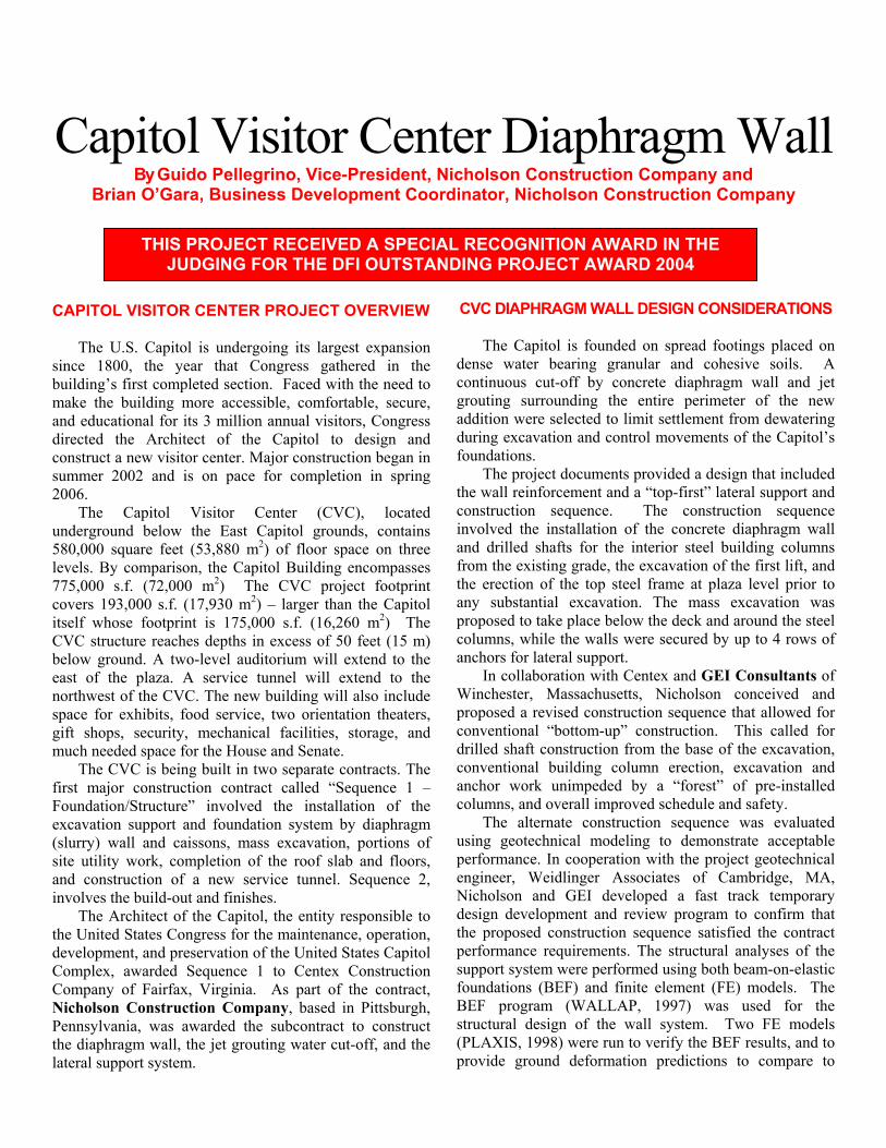
Capitol Visitor Center Diaphragm Wall
By Guido Pellegrino, Vice-President, Nicholson Construction Company and Brian O’Gara, Business Development Coordinator, Nicholson Construction Company
CAPITOL V The U.Ssince 1800,building’s fimake the buand educatiodirected theconstruct a nsummer 2002006.
The Cunderground580,000 squlevels. By c775,000 s.f.covers 193,0itself whoseCVC structubelow grouneast of the northwest ofspace for exgift shops, much needed The CVCfirst major Foundation/Sexcavation s(slurry) walsite utility wand construinvolves the The Arcthe United SdevelopmentComplex, aCompany ofNicholson CPennsylvaniathe diaphraglateral suppo
THIS PROJECT RECEIVED A SPECIAL RECOGNITION AWARD IN THE JUDGING FOR THE DFI OUTSTANDING PROJECT AWARD 2004
CVC DIAPHRAGM WALL DESIGN CONSIDERATIONS ISITOR CENTER PROJECT OVERVIEW The Capitol is founded on spread footings placed on dense water bearing granular and cohesive soils. A continuous cut-off by concrete diaphragm wall and jet grouting surrounding the entire perimeter of the new addition were selected to limit settlement from dewatering during excavation and control movements of the Capitol’s foundations.
. Capitol is undergoing its largest expansion the year that Congress gathered in the rst completed section. Faced with the need to ilding more accessible, comfortable, secure, nal for its 3 million annual visitors, Congress Architect of the Capitol to design and ew visitor center. Major construction began in 2 and is on pace for completion in spring The project documents provided a design that included
the wall reinforcement and a “top-first” lateral support and construction sequence. The construction sequence involved the installation of the concrete diaphragm wall and drilled shafts for the interior steel building columns from the existing grade, the excavation of the first lift, and the erection of the top steel frame at plaza level prior to any substantial excavation. The mass excavation was proposed to take place below the deck and around the steel columns, while the walls were secured by up to 4 rows of anchors for lateral support.
apitol Visitor Center (CVC), located below the East Capitol grounds, contains are feet (53,880 m2) of floor space on three omparison, the Capitol Building encompasses (72,000 m2) The CVC project footprint 00 s.f. (17,930 m2) – larger than the Capitol footprint is 175,000 s.f. (16,260 m2) The re reaches depths in excess of 50 feet (15 m) d. A two-level auditorium will extend to the plaza. A service tunnel will extend to the the CVC. The new building will also include hibits, food service, two orientation theaters, security, mechanical facilities, storage, and space for the House and Senate.
In collaboration with Centex and GEI Consultants of Winchester, Massachusetts, Nicholson conceived and proposed a revised construction sequence that allowed for conventional “bottom-up” construction. This called for drilled shaft construction from the base of the excavation, conventional building column erection, excavation and anchor work unimpeded by a “forest” of pre-installed columns, and overall improved schedule and safety.
is being built in two separate contracts. The construction contract called “Sequence 1 – tructure” involved the installation of the upport and foundation system by diaphragm l and caissons, mass excavation, portions of ork, completion of the roof slab and floors,
ction of a new service tunnel. Sequence 2, build-out and finishes.
The alternate construction sequence was evaluated using geotechnical modeling to demonstrate acceptable performance. In cooperation with the project geotechnical engineer, Weidlinger Associates of Cambridge, MA, Nicholson and GEI developed a fast track temporary design development and review program to confirm that the proposed construction sequence satisfied the contract performance requirements. The structural analyses of the support system were performed using both beam-on-elastic foundations (BEF) and finite element (FE) models. The BEF program (WALLAP, 1997) was used for the structural design of the wall system. Two FE models (PLAXIS, 1998) were run to verify the BEF results, and to provide ground deformation predictions to compare to
hitect of the Capitol, the entity responsible to tates Congress for the maintenance, operation, , and preservation of the United States Capitol warded Sequence 1 to Centex Construction Fairfax, Virginia. As part of the contract, onstruction Company, based in Pittsburgh, , was awarded the subcontract to construct
m wall, the jet grouting water cut-off, and the rt system.
contract requirements. Soil properties were selected based on geotechnical laboratory testing, as well as published values from test section case histories in the Washington, D.C. area.
During the duration of diaphragm wall installation and mass excavation, the building and the surrounding ground were closely monitored to detect any deflection or movement. A dense array of monitoring points, inclinometers, piezometers, and seismographs were continuously monitored to assess the ground response to the various construction activities, while the building itself was monitored by dedicated instrumentation.
The project’s primary design concern was the control and minimization of the Capitol’s movements. The diaphragm wall foundation was designed to achieve this goal and to act as a permanent water cut-off and structural wall for the three-level underground structure. Particular consideration was given to the fact that the Capitol’s foundations are within two feet (600mm) of the wall in some locations.
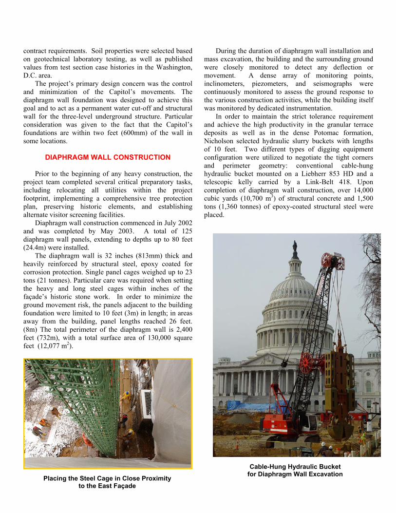
In order to maintain the strict tolerance requirement and achieve the high productivity in the granular terrace deposits as well as in the dense Potomac formation, Nicholson selected hydraulic slurry buckets with lengths of 10 feet. Two different types of digging equipment configuration were utilized to negotiate the tight corners and perimeter geometry: conventional cable-hung hydraulic bucket mounted on a Liebherr 853 HD and a telescopic kelly carried by a Link-Belt 418. Upon completion of diaphragm wall construction, over 14,000 cubic yards (10,700 m3) of structural concrete and 1,500 tons (1,360 tonnes) of epoxy-coated structural steel were placed.
DIAPHRAGM WALL CONSTRUCTION
Prior to the beginning of any heavy construction, the project team completed several critical preparatory tasks, including relocating all utilities within the project footprint, implementing a comprehensive tree protection plan, preserving historic elements, and establishing alternate visitor screening facilities.
Diaphragm wall construction commenced in July 2002 and was completed by May 2003. A total of 125 diaphragm wall panels, extending to depths up to 80 feet (24.4m) were installed. The diaphragm wall is 32 inches (813mm) thick and heavily reinforced by structural steel, epoxy coated for corrosion protection. Single panel cages weighed up to 23 tons (21 tonnes). Particular care was required when setting the heavy and long steel cages within inches of the façade’s historic stone work. In order to minimize the ground movement risk, the panels adjacent to the building foundation were limited to 10 feet (3m) in length; in areas away from the building, panel lengths reached 26 feet. (8m) The total perimeter of the diaphragm wall is 2,400 feet (732m), with a total surface area of 130,000 square feet (12,077 m2).
Cable-Hung Hydraulic Bucket for Diaphragm Wall Excavation
Placing the Steel Cage in Close Proximity to the East Façade
During the mass excavation of the CVC site, Nicholson installed over 500 temporary anchors, with capacities up to 375 kips (1,668 kN). The anchors were installed using the duplex drilling method to minimize ground disturbance and loss under the building foundations. A tri-dimensional model of the anchor configuration was developed to avoid reciprocal interferences in the inside corner areas. Internal steel bracing was also used in limited areas. The anchors were progressively detensioned as the construction of the concrete slabs and floors proceeded.
One of the unique challenges of this project was the extremely tight security measures under which all construction activities took place. All workers were subject to background checking, security screening on a daily basis, all delivery trucks were also x-rayed and inspected.
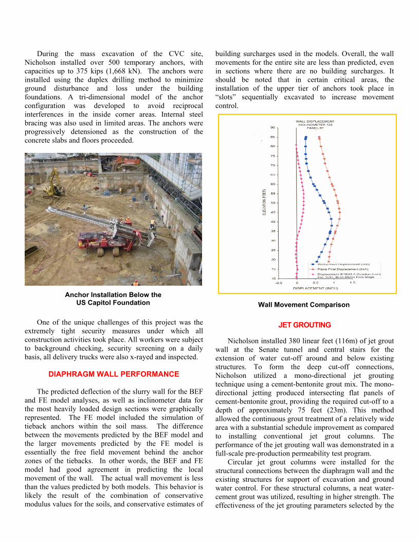
DIAPHRAGM WALL PERFORMANCE The predicted deflection of the slurry wall for the BEF and FE model analyses, as well as inclinometer data for the most heavily loaded design sections were graphically represented. The FE model included the simulation of tieback anchors within the soil mass. The difference between the movements predicted by the BEF model and the larger movements predicted by the FE model is essentially the free field movement behind the anchor zones of the tiebacks. In other words, the BEF and FE model had good agreement in predicting the local movement of the wall. The actual wall movement is less than the values predicted by both models. This behavior is likely the result of the combination of conservative modulus values for the soils, and conservative estimates of
building surcharges used in the models. Overall, the wall movements for the entire site are less than predicted, even in sections where there are no building surcharges. It should be noted that in certain critical areas, the installation of the upper tier of anchors took place in “slots” sequentially excavated to increase movement control.
Anchor Installation Below the US Capitol Foundation
Wall Movement Comparison
JET GROUTING Nicholson installed 380 linear feet (116m) of jet grout wall at the Senate tunnel and central stairs for the extension of water cut-off around and below existing structures. To form the deep cut-off connections, Nicholson utilized a mono-directional jet grouting technique using a cement-bentonite grout mix. The mono-directional jetting produced intersecting flat panels of cement-bentonite grout, providing the required cut-off to a depth of approximately 75 feet (23m). This method allowed the continuous grout treatment of a relatively wide area with a substantial schedule improvement as compared to installing conventional jet grout columns. The performance of the jet grouting wall was demonstrated in a full-scale pre-production permeability test program. Circular jet grout columns were installed for the structural connections between the diaphragm wall and the existing structures for support of excavation and ground water control. For these structural columns, a neat water-cement grout was utilized, resulting in higher strength. The effectiveness of the jet grouting parameters selected by the
contractor was confirmed by the installation of a test column cluster. Jet grouting was also used to overcome an unforeseen condition at the site. During the excavation of the slurry wall against the US Capitol foundation, an ancient stone well was encountered; this occurrence caused loss of slurry during the excavation and work stoppage. The project team quickly reacted to this new condition devising the installation of a series of small diameter columns to protect the building granite block foundations. Subsequently, the entire area affected by the well was consolidated by double-fluid jet grouting utilizing a low-strength cement and bentonite grout. Eventually the diaphragm wall installation resumed through the consolidated obstruction and was completed successfully.
CONCLUSIONS As this article goes to press, the foundation and civil work is nearly finished and the fit-out of the CVC is in full swing. The alternative construction sequence proposed by
the contractor resulted in substantial savings in terms of schedule and overall cost to the project, while satisfying all the performance requirements and objectives of the modified top-down approach prescribed in the original contract documents. Also, the proposed conventional bottom-up construction method allowed for a safer construction and minimized the reworks. The foundation work, performed by DFI Member Nicholson Construction Company, won the prestigious 2004 Washington Building Congress Craftsmanship Award, aimed at recognizing quality in construction.
Installation of Structural Connections by Jet Grouting
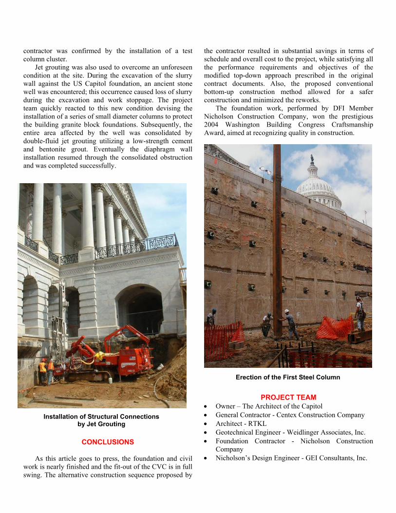
Erection of the First Steel Column
PROJECT TEAM • Owner – The Architect of the Capitol • General Contractor - Centex Construction Company • Architect - RTKL • Geotechnical Engineer - Weidlinger Associates, Inc. • Foundation Contractor - Nicholson Construction
Company • Nicholson’s Design Engineer - GEI Consultants, Inc.